


430i
This product is compliant with the |
|
applicable CE requirements. |
ASSEMBLY MANUAL / OWNER’S MANUAL |
|

Table of Contents
Important Safety Instructions - Assembly |
3 |
Operations |
28 |
Safety Warning Labels / Serial Number 4 |
Mounting and Dismounting |
28 |
|
Specifications |
5 |
Workout Incline Adjustment |
28 |
Before Assembly |
5 |
Power Up / Idle Mode |
29 |
Parts |
6 |
Quick Start Program |
30 |
Hardware |
7 |
User Profiles |
30 |
Tools |
7 |
Pausing or Stopping |
34 |
Assembly |
8 |
Results / Cool Down Mode |
35 |
Moving the Machine |
20 |
GOAL TRACK Statistics |
35 |
Leveling the Machine |
20 |
Console Service Mode |
37 |
|
|
Maintenance |
38 |
Important Safety Instructions |
21 |
Maintenance Parts |
39 |
Features |
22 |
Troubleshooting |
40 |
Console Features |
23 |
|
|
To validate warranty support, keep the original proof of purchase and record the following information:
Serial Number __________________________
Date of Purchase ____________________
To register your product warranty, contact your local distributor.
If you have questions or problems with your product, please contact your local Schwinn® distributor. To find your local distributor, go to: www.nautilusinternational.com
Nautilus, Inc., www.NautilusInc.com, 18225 NE Riverside Parkway, Portland, OR 97230, U.S.A. - Customer Service: technics@nautilus.com | Printed in China | © 2013 Nautilus, Inc.
2

Important Safety Instructions
-Assembly
This icon means a potentially hazardous situation which, if not avoided, could result in death or serious injury.
Obey the following warnings:
Read and understand all warnings on this machine.
Carefully read and understand the Assembly instructions.
•Keep bystanders and children away from the product you are assembling at all times.
•Do not connect power supply to the machine until instructed to do so.
•Do not assemble this machine outdoors or in a wet or moist location.
•Make sure assembly is done in an appropriate work space away from foot traffic and exposure to bystanders.
•Some components of the machine can be heavy or awkward. Use a second person when doing the assembly steps involving these parts. Do not do steps that involve heavy lifting or awkward movements on your own.
•Set up this machine on a solid, level, horizontal surface.
•Do not try to change the design or functionality of this machine. This could compromise the safety of this machine and will void the warranty.
•If replacement parts are necessary, use only genuine Nautilus® replacement parts and hardware. Failure to use genuine replacement parts can cause a risk to users, keep the machine from operating correctly and void the warranty.
•Do not use until the machine has been fully assembled and inspected for correct performance in accordance with the Manual.
•Read and understand the complete Manual supplied with this machine before first use. Keep the Manual for future reference.
•Do all assembly steps in the sequence given. Incorrect assembly can lead to injury or incorrect function.
•This product contains magnets. Magnetic fields can interfere with the normal use of certain medical devices at a close range. Users may come into proximity of the magnets in the assembly, maintenance, and/or use of the product. Given the obvious importance of these devices, such as a pacemaker, it is important that you consult with your medical provider in connection with the use of this equipment. Please consult the “Safety Warning Labels and Serial Number” section to determine the location of the magnets on this product.
3
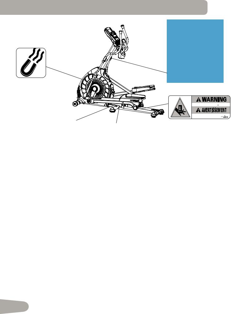
Safety Warning Labels and Serial
Number
• Read, understand and obey all warnings on this machine.
• Keep children away.
• Not intended for use by anyone under 14 years of age.
• Prior to use, read and understand the Owner’s Manual.
• Injury or death is possible if Caution is not used while using this machine.
• The maximum user weight for this machine is 300 lbs (136 kg).
• Replace any “Caution”, “Warning” or “Danger” label that is illegible, damaged, or removed.
• The heart rate displayed may be inaccurate and should be used for reference only.
•


•


Serial Number
Product Specifications
4
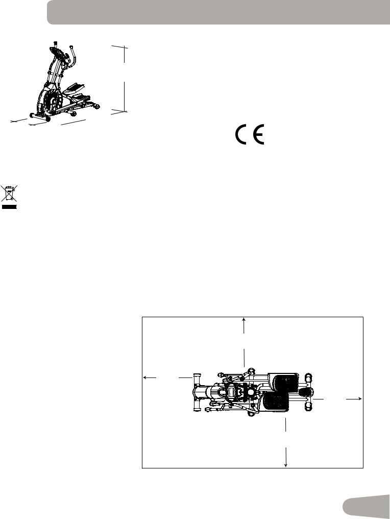
Specifications
160.5 cm ( 63.2” )
178.1 cm
71.5 cm  ( 70.1” ) ( 28.2” )
Maximum User Weight: |
136 kg ( 300 lbs. ) |
Machine Weight: |
74.5 kg ( 164.2 lbs. ) |
Total Surface Area (foot print) of equipment:
12734.2 cm2 ( 1976.8 inches2 )
Power Requirements:
Operational Voltage: 220V - 240V AC, 50Hz Operating Current: 0.4A
Regulatory Approvals:
This product conforms to the applicable EN ISO 20957 International Standards for Stationary Training Equipment, Class H.
DO NOT dispose of this product as refuse. This product is to be recycled. For proper disposal of this product, please follow the prescribed methods at an approved waste center.
Before Assembly
Select the area where you are going to set up and operate your machine. For safe operation, the location must be on a hard, level surface. Allow a workout area of a minimum 193.4 cm x 300 cm ( 76.2” x 118.1” ). Be sure that the workout space you are utilizing has adequate height clearance, taking into consideration the height of the user and the maximum incline of the elliptical machine.
Basic Assembly Tips |
|
|
|
Follow these basic points when you |
|
3.0m ( 118.1” ) |
|
assemble your machine: |
|
|
|
• |
Read and understand the “Important |
|
|
|
Safety Instructions” before assem- |
|
0.6m |
|
bly. |
|
|
|
|
( 24” ) |
|
• |
Collect all the pieces necessary for |
|
|
|
each assembly step. |
|
|
• |
Using the recommended wrenches, |
|
0.6m |
|
turn the bolts and nuts to the right |
|
( 24” ) |
|
1.93m |
|
|
|
(clockwise) to tighten, and the left |
0.6m |
|
|
( 76.2” ) |
||
|
(counterclockwise) to loosen, unless |
||
|
( 24” ) |
||
|
instructed otherwise. |
|
|
|
|
|
|
• |
When attaching 2 pieces, lightly |
|
|
|
lift and look through the bolt holes |
|
|
|
to help insert the bolt through the |
|
0.6m |
|
holes. |
|
|
|
|
( 24” ) |
|
|
|
|
|
• |
The assembly can require 2 people. |
|
|
|
|
|
5 |
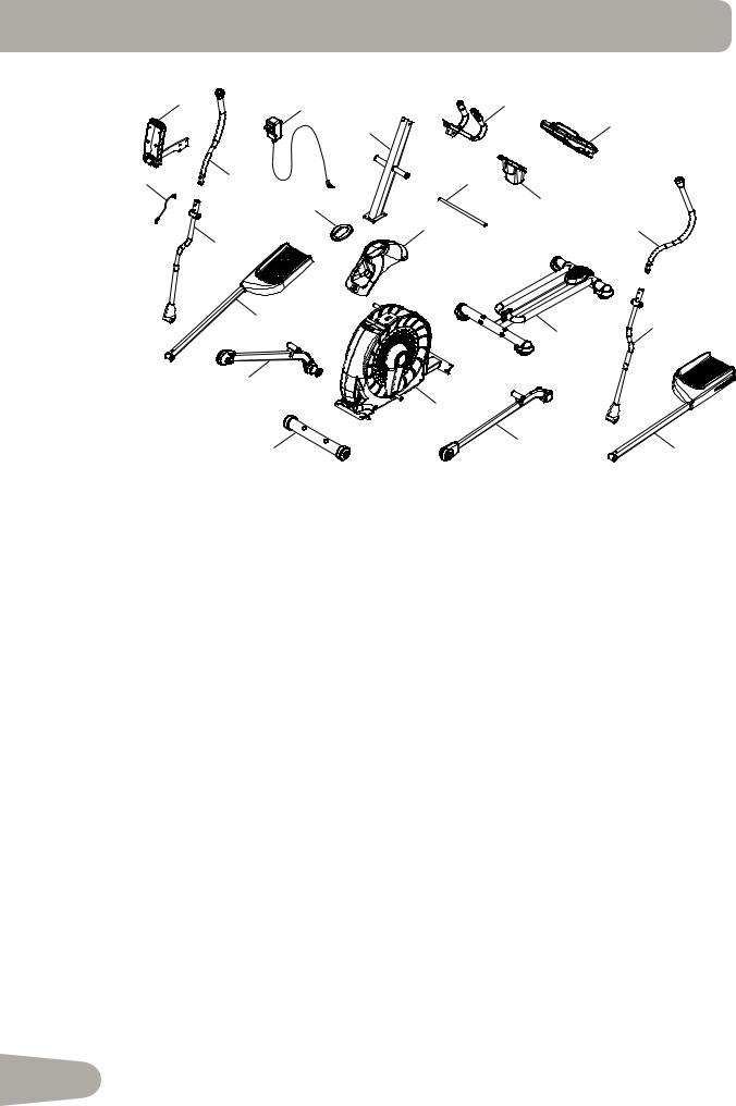
PARTS
|
21 |
19 |
2 |
|
|
||
|
|
1 |
5 |
|
|
|
|
20 |
|
18 |
3 |
|
|
16 |
4 |
|
|
12 |
6 |
|
|
17 |
|
15 |
9 |
7 |
|
||
|
|
14
|
11 |
|
13 |
10 |
8 |
|
A decal has been applied to all right (“ R ”) and left (“ L ”) parts to assist with assembly.
Item |
Qty |
Description |
Item |
Qty |
Description |
|
|
|
|
|
|
1 |
1 |
Console Mast |
12 |
1 |
Upper Shroud |
|
|
|
|
|
|
2 |
1 |
Static Handlebar |
13 |
1 |
Front Stabilizer |
|
|
|
|
|
|
3 |
1 |
Arm Pivot Rod |
14 |
1 |
Right Leg |
4 |
1 |
Water Bottle Holder |
15 |
1 |
Right Pedal |
|
|
|
|
|
|
5 |
1 |
Console |
16 |
1 |
Shroud Cap |
|
|
|
|
|
|
6 |
1 |
Upper Left Handlebar Arm |
17 |
1 |
Lower Right Handlebar Arm |
|
|
|
|
|
|
7 |
1 |
Lower Left Handlebar Arm |
18 |
1 |
Upper Right Handlebar Arm |
|
|
|
|
|
|
8 |
1 |
Left Pedal |
19 |
1 |
AC Adapter |
|
|
|
|
|
|
9 |
1 |
Rail Assembly |
20 |
1 |
MP3 Cord |
|
|
|
|
|
|
10 |
1 |
Left Leg |
21 |
1 |
Manual Lift Assembly |
|
|
|
|
|
|
11 |
1 |
Frame |
|
|
|
|
|
|
|
|
|
6
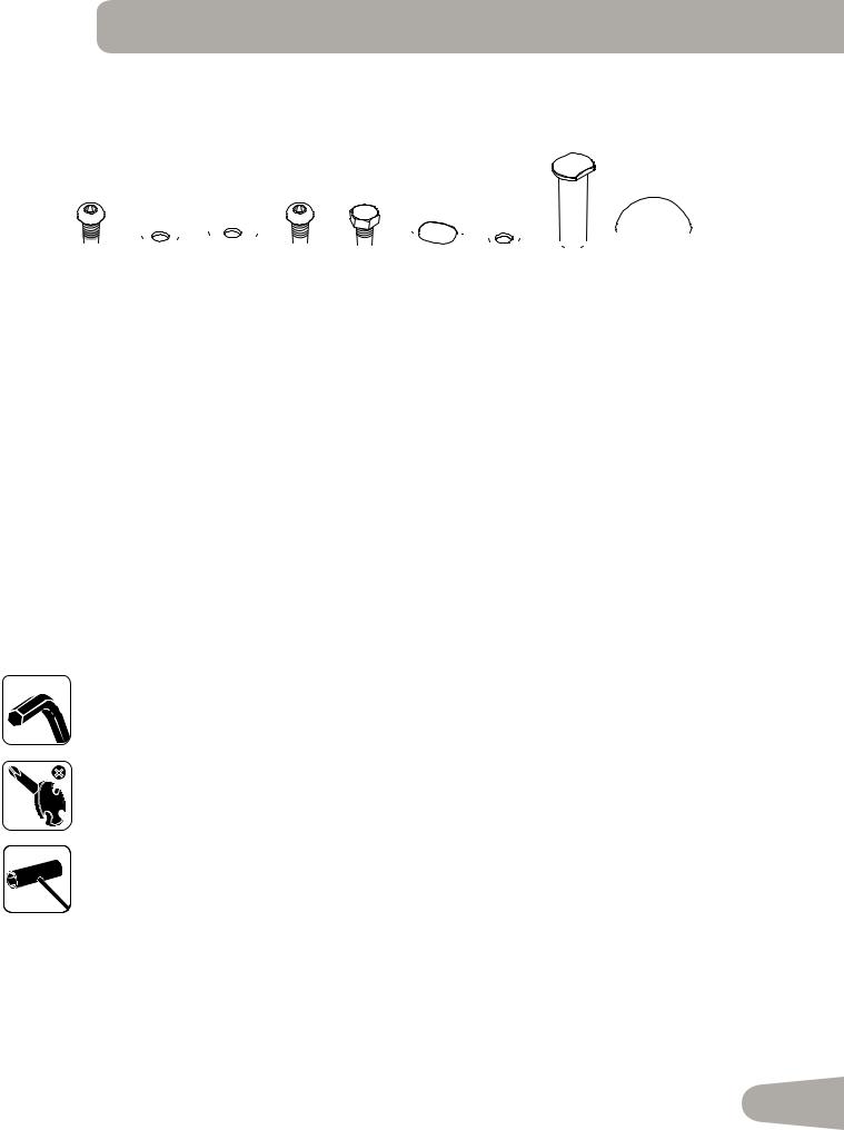
HARDWARE / TOOLs
A B
B C
C D
D  E
E  F
F G
G
 H
H I
I
Item |
Qty |
Description |
Item |
Qty |
Description |
|
|
|
|
|
|
A |
6 |
Button Head Hex Screw, M8x16 (with |
F |
6 |
Wave Washer |
|
|
Loctite® adhesive) |
|
|
|
B |
4 |
Flat Washer, M8 |
G |
12 |
Lock Washer, M8 |
|
|
|
|
|
|
C |
8 |
Wide Washer, M8 |
H |
2 |
Pivot Sleeve |
|
|
|
|
|
|
D |
4 |
Button Head Hex Screw, M8x16 |
I |
2 |
Cap |
|
|
|
|
|
|
E |
2 |
Hex Bolt, M8x20 |
|
|
|
|
|
|
|
|
|
Tools
Included
6 mm
#2
13 mm
15 mm
19 mm
7
ASSEMBLY
1. Attach Front Stabilizer to Frame
Note: Hardware is pre-installed and not on the Hardware Card. *
11
6mm
X4
* 
*
*
13
8
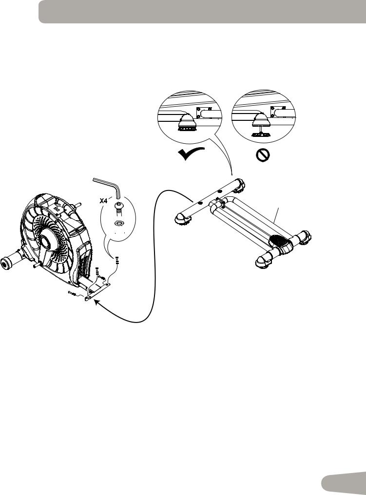
2. Attach Rail Assembly to Frame Assembly
Note: Be sure Levelers are fully raised on Rail Assembly. Hardware is pre-installed and not on the Hardware Card. *
6mm
9
* 
*

*
9

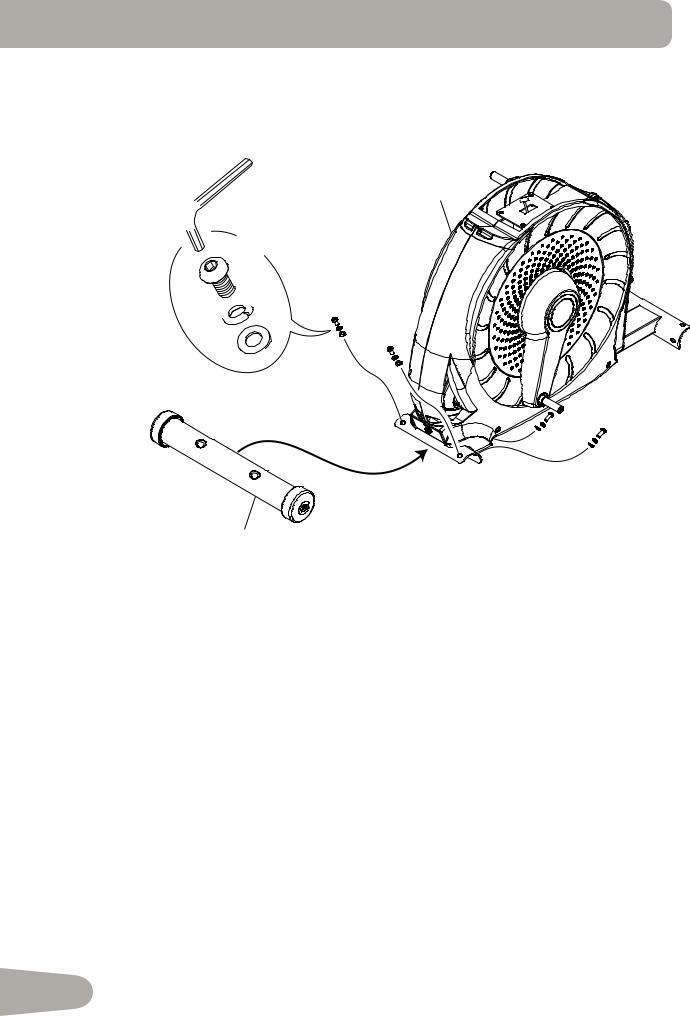
3. Attach the Manual Lift Assembly using the Arm Pivot Rod
Note: Hardware is pre-installed and not on the Hardware Card. *
NOTICE: With the Arm Pivot Rod under the plate junction, push the Manual Lift Assembly toward the Frame Assembly and fully tighten hardware. Remove the Arm Pivot Rod after tightening.
 Keep fingers away from any pinch opportunities when placing or removing the Arm Pivot Rod.
21
*
 *
*
3
10
4. Connect the Cable and Attach the Console Mast to Frame Assembly
NOTICE: Do not crimp Console Cable.
6mm 
X4
1 |
D |

 G
G
 B
B
12
11
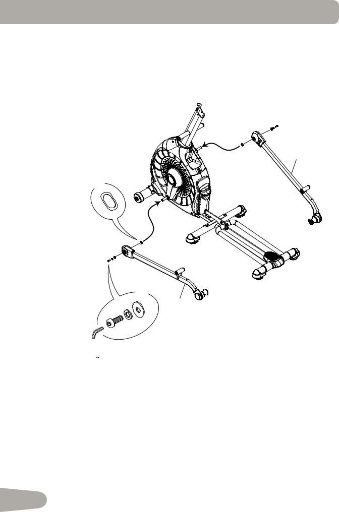
5. Attach Legs to Frame Assembly
14
X2
F
X2
10
 C
C
G
A
 6mm
6mm
12
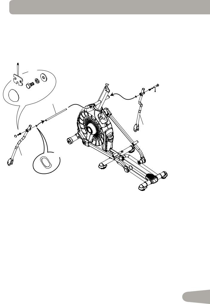
6. Attach Arm Pivot Rod and Lower Handlebar Arms to Frame Assembly
X2
13 mm
|
G |
C |
|
|
|
|
E |
|
I |
|
3 |
17
X2
7
F
13
 Loading...