


130 / 


 1.0
1.0
Manual en Español Latino Americano: |
ASSEMBLY MANUAL / OWNER’S MANUAL |
http://www.schwinnfitness.com |

Table of Contents
Important Safety Instructions - Assembly |
3 |
Important Safety Instructions - Owner’s |
15 |
Safety Warning Labels / Serial Number |
4 |
Features |
16 |
Specifications |
4 |
Console Features |
17 |
Before Assembly |
5 |
Contact Heart Rate (CHR) |
20 |
Parts |
6 |
Operations |
22 |
Hardware |
7 |
Adjustments |
22 |
Tools |
7 |
Initial Setup |
22 |
Assembly |
8 |
Quick Start / Manual Program |
23 |
Leveling the Bike |
14 |
User Profiles |
23 |
Moving the Bike |
14 |
Profile Programs |
25 |
|
|
Pausing or Stopping |
27 |
|
|
Results |
27 |
|
|
GOAL TRACK Statistics |
28 |
|
|
Console Setup Mode |
30 |
|
|
Maintenance |
31 |
|
|
Troubleshooting |
33 |
|
|
Warranty |
35 |
|
|
Sears Customer Warranty |
36 |
To validate warranty support, keep the original proof of purchase and record the following information:
Serial Number __________________________
Date of Purchase ____________________
To register your product warranty , go to: www.SchwinnFitness.com/register Or call 1 (800) 605–3369.
If you have questions or problems with your product, please call 1 (800) NAUTILUS (628–8458) Or go to: www.SchwinnFitness.com
Nautilus, Inc., (800) NAUTILUS / (800) 628-8458, www.NautilusInc.com - Customer Service: North America (800) 605-3369, csnls@nautilus.com | outside U.S. +01-360-859-5180, technics@nautilus.com | © 2013 Nautilus, Inc.
2

Important Safety Instructions
— ASSEMBLY
!This icon means a potentially hazardous situation which, if not avoided, could result in death or serious injury.
Obey the following warnings:
!Read and understand all warnings on this machine. Carefully read and understand the Assembly instructions.
•Keep bystanders and children away from the product you are assembling at all times.
•Do not connect power supply to the machine until instructed to do so.
•Do not assemble this machine outdoors or in a wet or moist location.
•Make sure assembly is done in an appropriate work space away from foot traffic and exposure to bystanders.
•Some components of the machine can be heavy or awkward. Use a second person when doing the assembly steps involving these parts. Do not do steps that involve heavy lifting or awkward movements on your own.
•Set up this machine on a solid, level, horizontal surface.
•Do not try to change the design or functionality of this machine. This could compromise the safety of this machine and will void the warranty.
•If replacement parts are necessary, use only genuine Nautilus® replacement parts and hardware. Failure to use genuine replacement parts can cause a risk to users, keep the machine from operating correctly and void the warranty.
•Do not use until the machine has been fully assembled and inspected for correct performance in accordance with the
Manual.
•Read and understand the complete Manual supplied with this machine before first use. Keep the Manual for future reference.
•Do all assembly steps in the sequence given. Incorrect assembly can lead to injury or incorrect function.
•This product contains magnets. Magnetic fields can interfere with the normal use of certain medical devices at a close range. Users may come into proximity of the magnets in the assembly, maintenance, and/or use of the product. Given the obvious importance of these devices, such as a pacemaker, it is important that you consult with your medical provider in connection with the use of this equipment. Please consult the “Safety Warning Labels and Serial Number” section to determine the location of the magnets on this product.
3
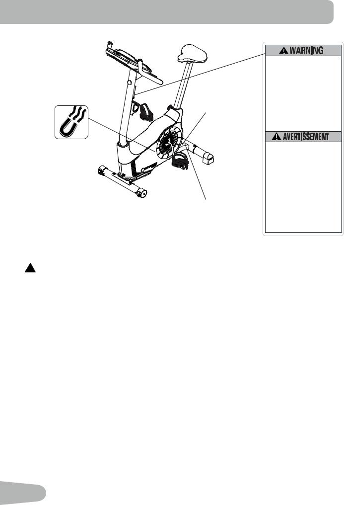
Safety Warning Labels and Serial Number
Serial number
Product specification
•Read, understand and obey all warnings on this machine.
•Keep children away.
•Not intended for use by anyone under 14 years of age.
•Prior to use, read and understand the Owner’s Manual.
•Injury or death is possible if Caution is not used while using this machine.
•The maximum user weight for this machine is 300 lbs (136 kg).
•Replace any “Caution”, “Warning” or “Danger” label that is illegible, damaged, or removed.
•The heart rate displayed may be inaccurate and should be used for reference only.
•Lisez et assimilez tous les avertissements apposés sur cet appareil.
•Gardez les enfants et les animaux de compagnie éloignés de cette machine en tout temps
•Déconseillé aux enfants âgés de moins de 14 ans.
•Lisez et familiarisez-vous avec le Manuel du propriétaire et avec tous les avertissements avant d’utiliser cette machine.
•Soyez prudent lorsque vous utilisez cet équipement pour ne pas vous infliger de graves blessures.
•Cette machine supporte un poids maximal de 300lbs. (136kg).
•Remplacez toute étiquette d’avertissement endommagée, illisible ou manquante.
•La fréquence cardiaque qui s’affiche sur la console peut être inexact et doit être utilisée seulement à titre
indicatif.
FCC Compliance
!Changes or modifications to this unit not expressly approved by the party responsible for compliance could void the user’s authority to operate the equipment.
The machine and power supply comply with part 15 of the FCC rules. Operation is subject to the following two conditions: (1) This device may not cause harmful interference, and (2) this device must accept any interference received, including interference that may cause undesired operation.
Note: This machine and power supply have been tested and found to comply with the limits for a Class B digital device, pursuant to Part 15 of the FCC Rules. These limits are designed to provide reasonable protection against harmful interference in a residential installation. This equipment generates, uses and can radiate radio frequency energy and, if not installed and used in accordance with the instructions, may cause harmful interference to radio communications.
However, there is no guarantee that interference will not occur in a particular installation. If this equipment does cause harmful interference to radio or television reception, which can be determined by turning the equipment off and on, the user is encouraged to try to correct the interference by one or more of the following measures:
•Reorient or relocate the receiving antenna.
•Increase the separation between the equipment and receiver.
•Connect the equipment into an outlet on a circuit different from that to which the receiver is connected.
•Consult the dealer or an experienced radio/TV technician for help.
4
Specifications
Maximum User Weight: 300 lbs. (136 kg)
Power Requirements:
Operational Voltage: 9VDC
Operating Current: 1.5A
Regulatory Approvals:
ISO 20957
AC Power Adapter: UL listed, Rated 120V 60Hz Input, 9VDC, 1500mA Output. Class 2.
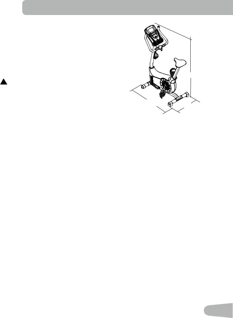
55.6” (141cm)
! This product, its packaging, and components contain chemicals known to the State of California to cause cancer, birth defects, or reproductive harm. This Notice is provided in accordance with California’s Proposition
65. If you would like additional information, please refer |
41.3” (105cm) |
|
|
to our website at www.nautilus.com/prop65. |
21.4” (54cm) |
||
|
Before Assembly
Select the area where you are going to set up and operate your machine. For safe operation, the location must be on a hard, level surface. Allow a workout area of a minimum 90” x 70” (2.3m x 1.8m).
Basic Assembly Tips
Follow these basic points when you assemble your machine:
1.Read and understand the “Important Safety Instructions” before assembly.
2.Collect all the pieces necessary for each assembly step.
3.Using the recommended wrenches, turn the bolts and nuts to the right (clockwise) to tighten, and the left (counterclockwise) to loosen, unless instructed otherwise.
4.When attaching 2 pieces, gently lift and look through the bolt holes to help insert the bolt through the holes.
5.The assembly can require 2 people.
5
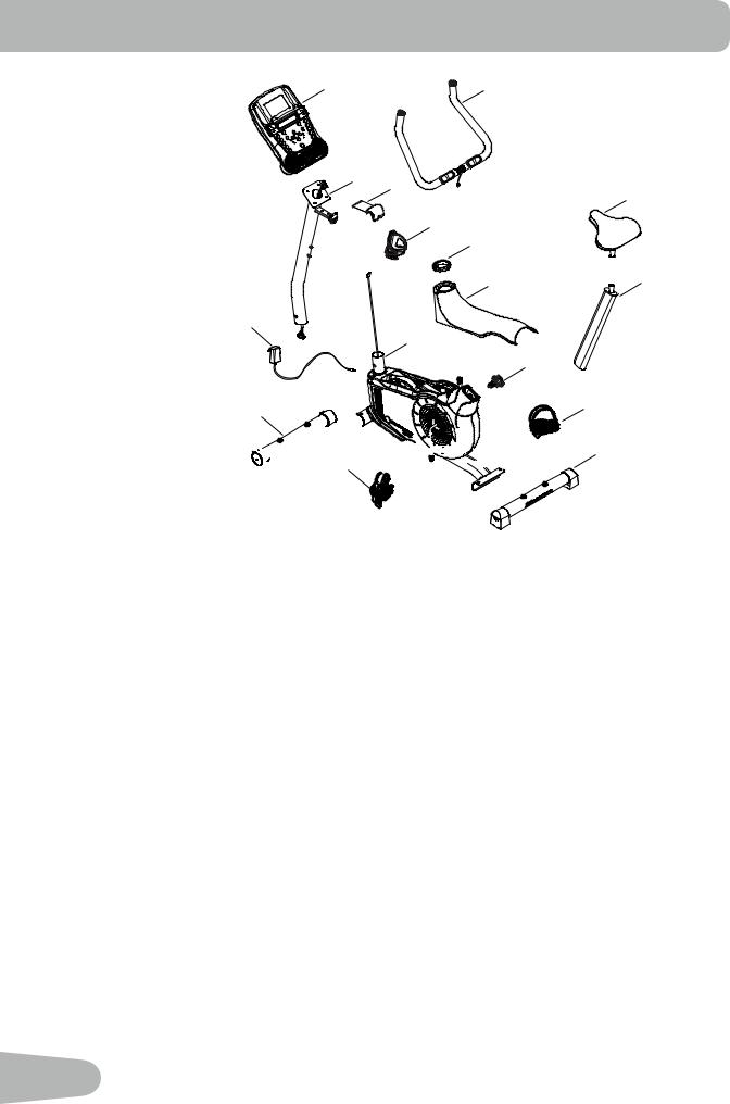
PARTS
8 |
7 |
6 16
11
14
5
4 |
9 |
15
1
10
13 (R)
2


 3
3  12 (L)


Item |
Qty |
Description |
Item |
Qty |
Description |
|
|
|
|
|
|
1 |
1 |
Main Frame |
9 |
1 |
Seat Post |
|
|
|
|
|
|
2 |
1 |
Front Stabilizer |
10 |
1 |
Adjustment Knob |
3 |
1 |
Rear Stabilizer |
11 |
1 |
Seat |
|
|
|
|
|
|
4 |
1 |
Top Shroud |
12 |
1 |
Left Pedal (L) |
|
|
|
|
|
|
5 |
1 |
Mast Gasket |
13 |
1 |
Right Pedal (R) |
|
|
|
|
|
|
6 |
1 |
Console Mast (with Handlebar Mount) |
14 |
1 |
Water Bottle Holder |
|
|
|
|
|
|
7 |
1 |
Handlebars |
15 |
1 |
AC Adapter |
|
|
|
|
|
|
8 |
1 |
Console |
16 |
1 |
Handlebar Mount Cover |
|
|
|
|
|
|
Note: Media Cable is in a bag.
6
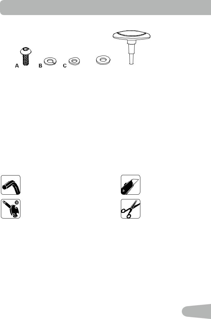
HARDWARE / TOOLs
D E
Item |
Qty |
Description |
|
|
|
A |
4 |
Button Head Hex Screw M8 x 25 |
|
|
|
B |
5 |
Lock Washer M8 |
C |
4 |
Curved Washer M8 |
|
|
|
D |
1 |
Flat Washer M8 |
|
|
|
E |
1 |
T-handle |
|
|
|
Tools
Included |
Not Included |
6 mm |
(recommended) |
7
, Journey 1.0 Upright Bike Owner's Manual")
ASSEMBLY
1. Attach Stabilizers to Main Frame
Note: Hardware(*) is pre-installed on the stabilizers and not on Hardware Card. Make sure transport wheels on the front stabilizer point forward, and the Schwinn® decal on the rear stabilizer faces outward from the machine.
6 mm
|
|
6 mm |
X2 |
* |
* X2 |
|
|
|
|
* |
* |
|
* |
|
|
* |
|
|
|
2. Install Console Mast, Mast Gasket and Top Shroud on Main Assembly
NOTICE: Make sure the Console Cable connector (a) does not fall into the Console Mast. Align the clips on the cable connectors and make sure the connectors lock. Do not crimp Console Cable. Be sure the tabs on the Top
Shroud snap into the Main Assembly.


 a
a
6
5
|
|
X4 |
C |
B |
6 mm |
|
||
|
A |
|
|
|
8
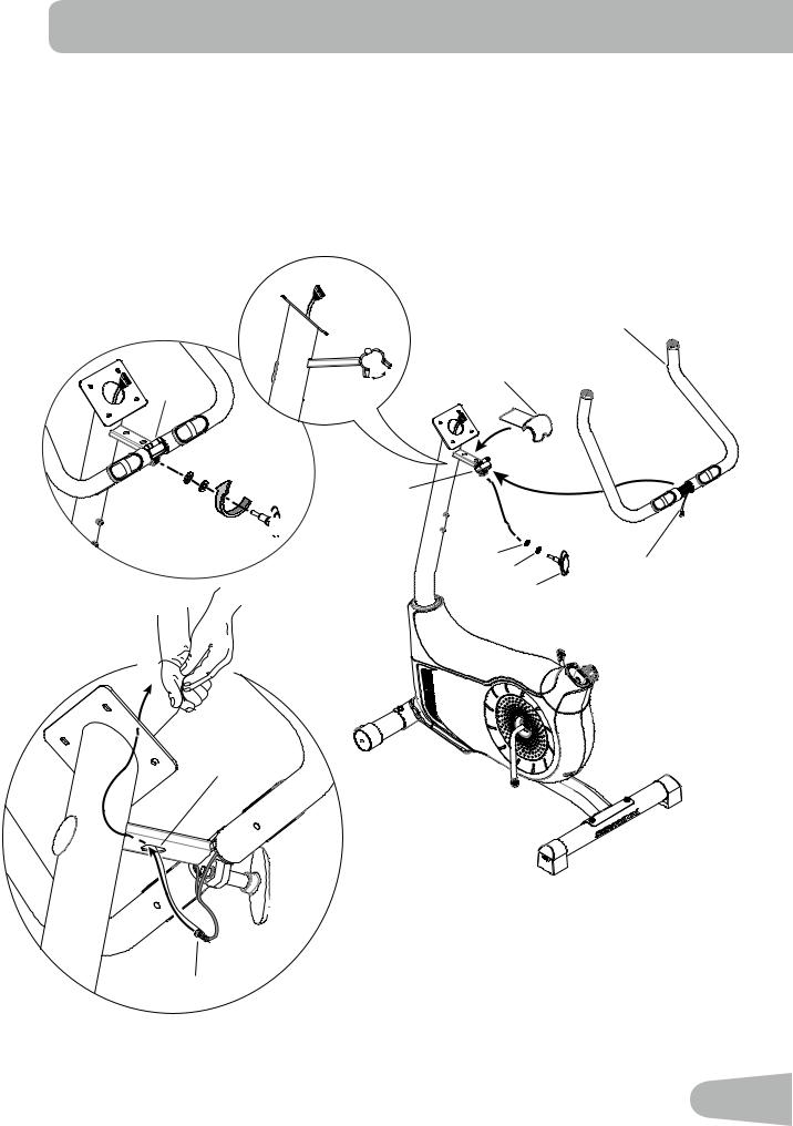
3. Install Handlebars on Console Mast
NOTICE: Do not crimp the cables. Put the Handlebar (7) in the bracket (6a), adjust the Handlebar to the desired angle, and install the T-handle (E) through the holes. Use the pull cable in the Handlebar Mount to route the HR cable (7a) through the slot (6c) under the Handlebar Mount to the top of the mast. Fully tighten the T-handle to keep the Handlebar in position. Push the cover (16) into position on the Handlebar Mount.
7
6a |
16 |
6a |
B |
D |
6a |
|
|
E 


B |
D |
7a |
|
||
|
E |
|
|
|
6c
 E
E
7
7a
9
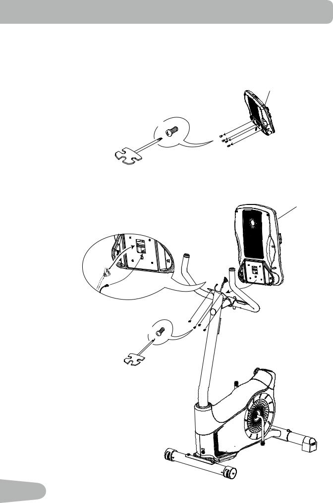
4. Install Console on Console Mast
Note: Remove the pre-installed screws(*) from the back of the Console before you connect the cables.
NOTICE: Do not crimp the cables.
8
X4
*
#2
8
X4


 *
*
#2
10
5. Install Seat Post on Frame
NOTICE: Make sure the Adjustment Knob engages the Seat Post.
 Do not set the Seat Post position higher than the stop mark (STOP) on the tube.
9
10
STOP
10 


6. Attach Seat to Seat Post
NOTICE: Be sure the Seat is straight. Tighten the nuts (11b) on the Seat bracket (11a) to hold the Seat in position.
11
11a
11b
11b


11
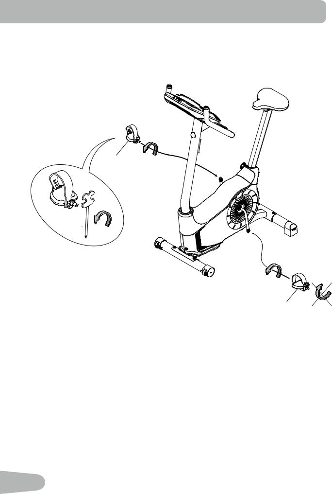
7. Install Pedals
Note: The Left Pedal is reverse-threaded. Be sure to attach Pedals on the proper side of the Bike. Orientation is based from a seated position on the bike. The Left Pedal has an “L”, the Right Pedal an “R”.
13 (R)
12 (L)
12
 Loading...