


Schwinn® 240 Recumbent Exercise Bike
003–3234.051812.D

Para obtener este manual en Español Latino Americano vaya a:
http://www.schwinnfitness.com.
Table of Contents
Important Safety Instructions |
3 |
Parts |
6 |
Specifications |
4 |
Assembly |
7 |
Before Assembly |
4 |
Level Your Bike |
24 |
Tools Required |
5 |
Contacts |
26 |
Hardware |
5 |
Instructions de montage |
27 |
To validate warranty support, keep the original proof of purchase and record the following information:
Serial Number __________________________
Date of Purchase ____________________
To register your product warranty , go to: www.schwinnfitness.com/register
Or call 1 (800) 605–3369.
If you have questions or problems with your product, please call 1 (800) NAUTILUS (628–8458).
2

Important Safety Instructions
This icon means a potentially hazardous situation which, if not avoided, could result in death or serious injury.
Obey the following warnings:
Read and understand all warnings on this machine.
Carefully read and understand the Assembly Manual.
•Keep bystanders and children away from the product you are assembling at all times.
•Do not connect power supply to the machine until instructed to do so.
•Do not assemble equipment in a wet or damp location.
•Make sure assembly is done in an appropriate work space away from foot traffic and exposure to bystanders.
•Some components of the machine can be heavy or awkward. Use a second person when doing the assembly steps involving these parts. Do not do steps that involve heavy lifting or awkward movements on your own.
•Do not try to change the design or functionality of this machine. This could compromise the safety and can void the warranty.
•If replacement parts are necessary use only genuine Schwinn® replacement parts and hardware supplied by Nautilus. Failure to use genuine replacement parts can cause a risk to users, keep the machine from operating correctly or void the warranty.
•Do not use or put the machine into service until the machine has been fully assembled and inspected for correct performance in accordance with the Owner’s Manual.
•Read and understand the complete Owner’s Manual supplied with this machine before first use. Keep the Owner’s Manual for future reference.
•Do all assembly steps in the sequence given. Incorrect assembly can lead to injury.
•This product contains magnets. Magnetic fields can interfere with the normal use of certain medical devices at a close range. Users may come into proximity of the magnets in the assembly, maintenance, and/or use of the product. Given the obvious importance of these devices, such as a pacemaker, it is important that you consult with your medical provider in connection with the use of this equipment. Please consult the “Safety Warning Labels and Serial Number” section to determine the location of the magnets on this product.
3
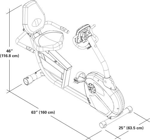
Specifications
Before Assembly
Select the area where you are going to set up and operate your machine. For safe operation, the location must be on a hard, level surface. Allow a workout area of minimum 103” x 65” (2.6m x 1.7m).
Follow these basic points when you assemble your machine:
1.Read and understand the “Important Safety Instructions” before assembly.
2.Collect all the pieces necessary for each assembly step.
3.Using the recommended wrenches, turn the bolts and nuts to the right (clockwise) to tighten, and the left (counterclockwise) to loosen, unless instructed otherwise.
4.When attaching 2 pieces, lightly lift and look through the bolt holes to help insert the bolt through
the holes.
5. The assembly requires 2 people.
4
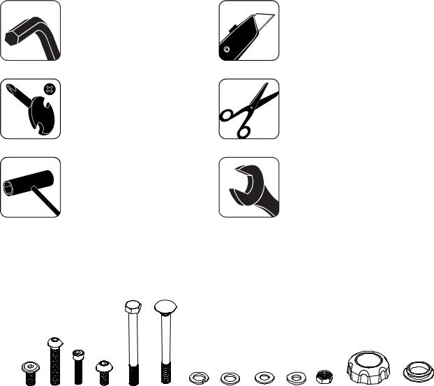
Tools
Included |
Not Included |
5mm
Hardware
A |
B |
C |
D |
E |
F |
G |
H |
I |
J |
K |
M |
N |
|
|
|
|
|
|
|
|
|
|
|
|
|
Item |
|
Qty |
Description |
|
|
|
|
Item |
Qty |
Description |
|
|
|
|
|
|
|
|
|
|
|
|
|
||
A |
|
4 |
M8 x 16 Hex Screw |
|
|
|
H |
1 |
Narrow Washer |
|
||
|
|
|
|
|
|
|
|
|
||||
B |
|
8 |
M8 x 45 Button Head Hex Screw |
|
|
I |
23 |
Flat Washer (9 pre-installed) |
||||
|
|
|
|
|
|
|
|
|
|
|
||
C |
|
1 |
M7 x 30 Hex Bolt |
|
|
|
J |
4 |
Arc Washer |
|
||
|
|
|
|
|
|
|
|
|
||||
D |
|
17 |
M8 x 16 Button Head Hex Screw (9 |
|
K |
1 |
M8 Lock Nut |
|
||||
|
|
|
pre-installed) |
|
|
|
|
|
|
|
|
|
|
|
|
|
|
|
|
|
|
|
|
||
E |
|
1 |
M8 x 85 Hex Bolt |
|
|
|
L |
- |
not used |
|
||
|
|
|
|
|
|
|
|
|
|
|||
F |
|
1 |
M8 x 85 Carriage Bolt |
|
|
|
M |
1 |
Console Adjustment Knob |
|||
|
|
|
|
|
|
|
|
|
|
|
|
|
G |
|
1 |
Lock Washer |
|
|
|
|
N |
4 |
Cover |
|
|
|
|
|
|
|
|
|
|
|
|
|
|
|
5
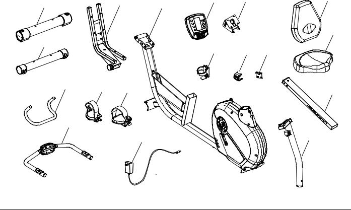
Parts
1 |
3 |
4 |
5 |
6 |
11 |
|
|
|
12
2
7 |
9 |
10 |
18 |
17 |
16 |
|
13
19
15 |
14 |
|
Item |
Qty |
Description |
Item |
Qty |
Description |
|
|
|
|
|
|
1 |
1 |
Rear Stabilizer |
11 |
1 |
Seat Back |
|
|
|
|
|
|
2 |
1 |
Front Stabilizer |
12 |
1 |
Seat Bottom |
|
|
|
|
|
|
3 |
1 |
Seat Frame |
13 |
1 |
Seat Rail |
|
|
|
|
|
|
4 |
1 |
Main Frame |
14 |
1 |
Console Mast |
|
|
|
|
|
|
5 |
1 |
Console |
15 |
1 |
Power Cord |
|
|
|
|
|
|
6 |
1 |
Console Bracket |
16 |
1 |
Left Pedal |
|
|
|
|
|
|
7 |
1 |
Water Bottle Holder |
17 |
1 |
Right Pedal |
|
|
|
|
|
|
8 |
– |
not used |
18 |
1 |
Upright Handlebar |
|
|
|
|
|
|
9 |
1 |
Handlebar Bracket |
19 |
1 |
Side Handlebar |
|
|
|
|
|
|
10 |
1 |
Seat Rail Bracket |
|
|
|
|
|
|
|
|
|
6
Assembly
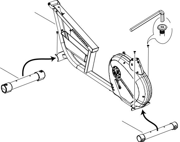
1. Attach Stabilizers to Main Frame
4
X4
 A
A
1
2
7
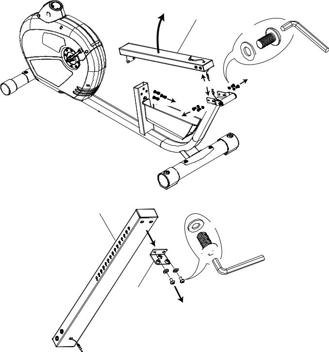
2. Prepare the Main Frame for Assembly
NOTICE: Disconnect the Heart Rate Cable. Make sure that the Heart Rate Cable does not fall into the frame tube.
13
X7
D
 I
I
13
X2
I
D 

10
8
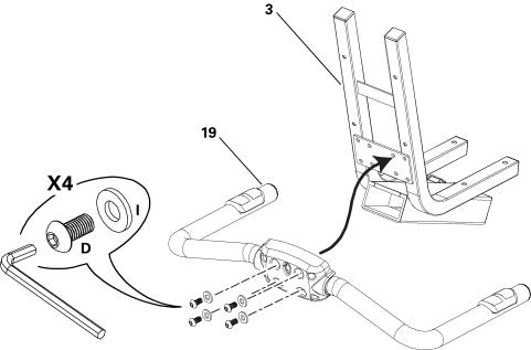
3. Attach Side Handlebars to Seat Frame
9
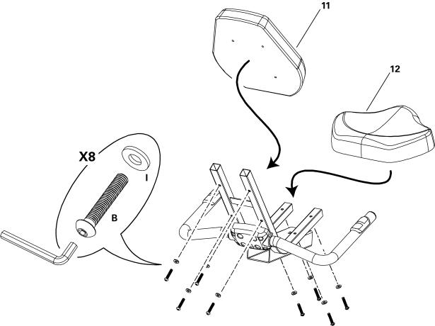
4. Attach Seat Pads to Seat Frame Assembly
10
5. Slide Seat Assembly onto Seat Rail
NOTICE: Do not crimp Heart Rate Cable.
11
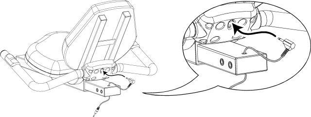
6. Connect Heart Rate Cable to Seat Assembly
12
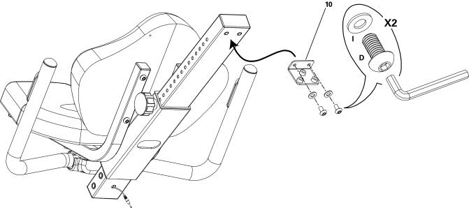
7. Install Seat Rail Bracket
13
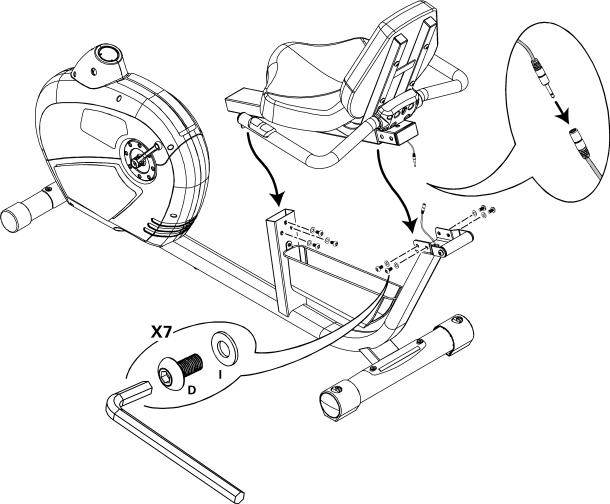
8. Install Seat Assembly to Frame Assembly
NOTICE: Do not crimp Heart Rate Cable.
14
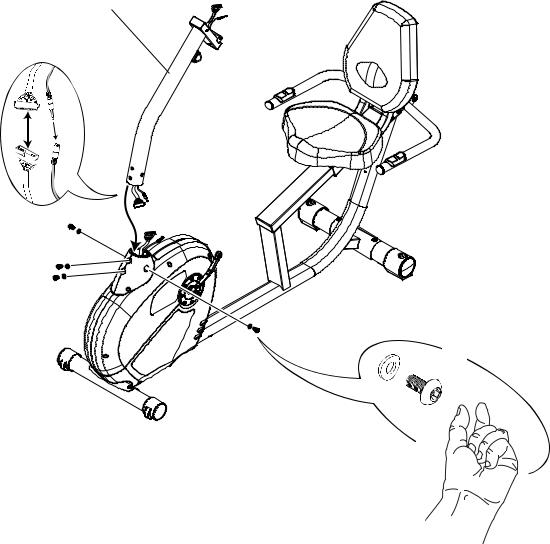
9. Attach Console Mast to Frame Assembly
NOTICE: Do not crimp Console Cables.
14
J |
X4 |
|
|
|
D |
15
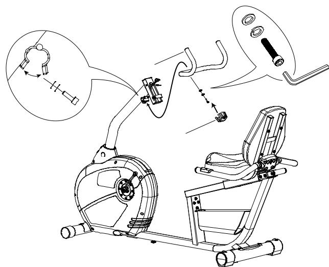
10. Attach Upright Handlebar to Console Mast
H
G
C
18
9
16
 Loading...