


450
Manual en Español Latino Americano: http://www.schwinnfitness.com
ASSEMBLY MANUAL / OWNER’S MANUAL

Table of Contents
Important Safety Instructions - Assembly |
3 |
Adjustments |
31 |
Safety Warning Labels / Serial Number |
4 |
Initial Setup |
33 |
Specifications |
5 |
Quick Start / Manual Program |
33 |
Before Assembly |
5 |
Guest User / Profile Program |
33 |
Parts |
6 |
User Setup Mode |
34 |
Hardware |
7 |
Profile Programs |
38 |
Tools |
7 |
Fitness Test |
39 |
Assembly |
8 |
Heart Rate Control Workout |
39 |
Moving the Machine |
21 |
Distance Goal Workout |
40 |
Leveling the Machine |
22 |
Results/Cool Down Mode |
40 |
Important Safety Instructions |
23 |
Pausing or Stopping |
41 |
User Statistics |
41 |
||
Features |
24 |
Console Setup Mode |
43 |
Console Features |
25 |
Maintenance |
45 |
Remote Heart Rate Monitor |
27 |
Troubleshooting |
48 |
Operations |
30 |
|
|
To validate warranty support, keep the original proof of purchase and record the following information: Serial Number __________________________
Date of Purchase ____________________
To register your product warranty , go to: www.SchwinnFitness.com/register Or call 1 (800) 605–3369.
If you have questions or problems with your product, please call 1 (800) NAUTILUS (628–8458).
Nautilus, Inc., (800) NAUTILUS / (800) 628-8458, www.NautilusInc.com - Customer Service: North America (800) 605-3369, csnls@nautilus.com | outside U.S. +01-360-859-5180, technics-APLA@nautilus.com | Printed in China | © 2011 Nautilus, Inc., All rights reserved. ™ and ® indicate a trademark or registered trademark. Nautilus, Inc. (www.NautilusInc.com) trademarks include NAUTILUS®, BOWFLEX®, SCHWINN® and UNIVERSAL® and respective logos. Other trademarks are the property of their respective owners
2

Important Safety Instructions
-Assembly
This icon means a potentially hazardous situation which, if not avoided, could result in death or serious injury.
Obey the following warnings:
Read and understand all warnings on this machine.
Carefully read and understand the Assembly instructions.
•Keep bystanders and children away from the product you are assembling at all times.
•Do not connect power supply to the machine until instructed to do so.
•Do not assemble this machine outdoors or in a wet or moist location.
•Make sure assembly is done in an appropriate work space away from foot traffic and exposure to bystanders.
•Some components of the machine can be heavy or awkward. Use a second person when doing the assembly steps involving these parts. Do not do steps that involve heavy lifting or awkward movements on your own.
•Set up this machine on a solid, level, horizontal surface.
•Do not try to change the design or functionality of this machine. This could compromise the safety of this machine and will void the warranty.
•If replacement parts are necessary, use only genuine Nautilus® replacement parts and hardware. Failure to use genuine replacement parts can cause a risk to users, keep the machine from operating correctly and void the warranty.
•Do not use until the machine has been fully assembled and inspected for correct performance in accordance with the Manual.
•Read and understand the complete Manual supplied with this machine before first use. Keep the Manual for future reference.
•Do all assembly steps in the sequence given. Incorrect assembly can lead to injury or incorrect function.
3
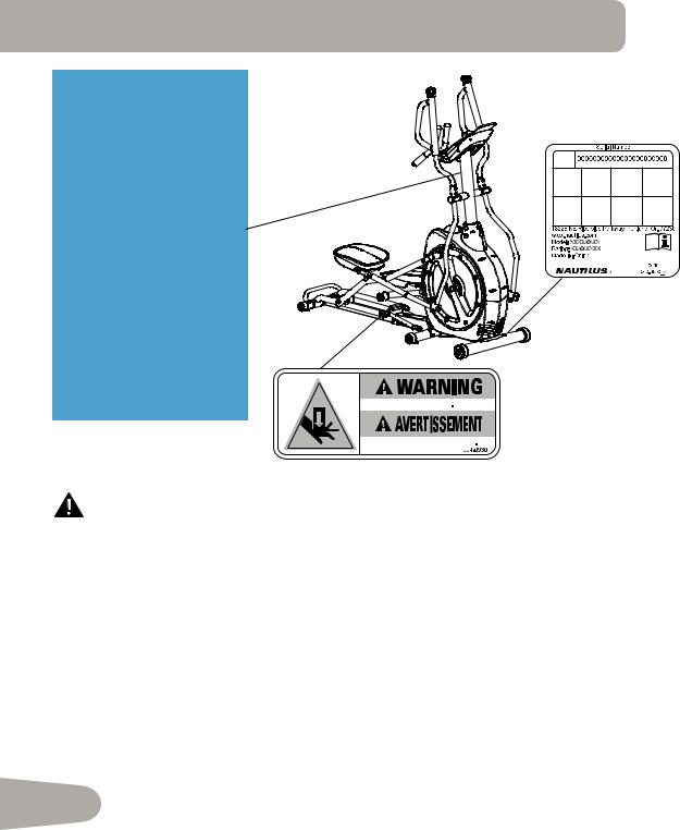
Safety Warning Labels and
Serial Number
•Keep children away.
•Prior to use, read and understand the Owners Manual.
•Injury or death is possible if Caution is not used while using this machine.
•The maximum user weight for this machine is 300 lbs (136 Kg).
•Replace any “Caution” “Warning” or “Danger” label that is illegible, damaged, or removed.
•This machine is for home use only.
• 


•


•


•


300lbs. (136kg).
•


•
•


•


FCC Compliance
Changes or modifications to this unit not expressly approved by the party responsible for compliance could void the user’s authority to operate the equipment.
The power supply complies with part 15 of the FCC rules. Operation is subject to the following two conditions: (1) This device may not cause harmful interference, and (2) this device must accept any interference received, including interference that may cause undesired operation.
Note: This power supply has been tested and found to comply with the limits for a Class B digital device, pursuant to Part 15 of the FCC Rules. These limits are designed to provide reasonable protection against harmful interference in a residential installation. This equipment generates, uses and can radiate radio frequency energy and, if not installed and used in accordance with the instructions, may cause harmful interference to radio communications.
However, there is no guarantee that interference will not occur in a particular installation. If this equipment does cause harmful interference to radio or television reception, which can be determined by turning the equipment off and on, the user is encouraged to try to correct the interference by one or more of the following measures:
•Reorient or relocate the receiving antenna.
•Increase the separation between the equipment and receiver.
•Connect the equipment into an outlet on a circuit different from that to which the
4receiver is connected.
• Consult the dealer or an experienced radio/TV technician for help.
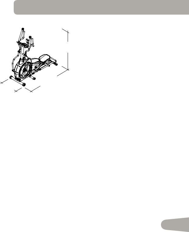
Specifications
|
|
Maximum User Weight: |
300 lbs. (136 kg) |
|
68.3” |
Maximum Inclined Pedal Height: 19 inches |
|
|
|
|
|
|
(173.6 cm) |
Power Requirements: |
|
|
|
|
|
|
|
Operational Voltage: |
Operational Voltage 9VDC |
|
|
Operating Current: |
1500 mA |
|
|
Regulatory Approvals: |
|
|
70.4” |
AC Power Adapter: |
UL listed, CSA certified (or |
|
|
equivalent), Rated 120V 60Hz |
|
26.1” |
(178.9 cm) |
|
Input, 9VDC, 1500mA Out- |
(66.3 cm) |
|
|
put. Class 2 or LPS. |
Before Assembly
Select the area where you are going to set up and operate your machine. For safe operation, the location must be on a hard, level surface. Allow a workout area of a minimum 74.1” x 118.4” (188.2 cm x 300.7 cm). Be sure that the workout space you are utilizing has adequate height clearance, taking into consideration the height of the user and the maximum incline of the elliptical machine.
Basic Assembly Tips
Follow these basic points when you assemble your machine:
•Read and understand the “Important Safety Instructions” before assembly.
•Collect all the pieces necessary for each assembly step.
•Using the recommended wrenches, turn the bolts and nuts to the right (clockwise) to tighten, and the left (counterclockwise) to loosen, unless instructed otherwise.
•When attaching 2 pieces, lightly lift and look through the bolt holes to help insert the bolt through the holes.
•The assembly requires 2 people.
5
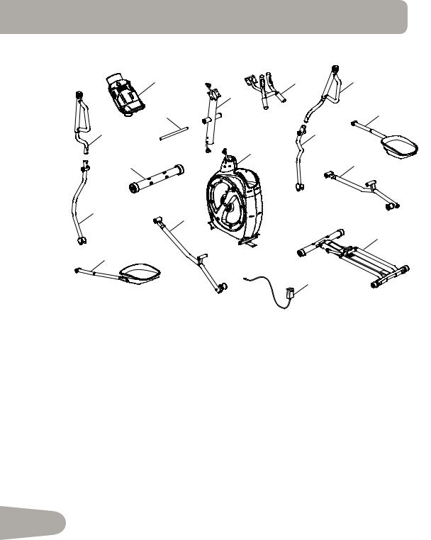
PARTS
1 |
4 |
5 |
|
3 |
|
2 |
|
6 |
16 |
|
7 |
|
8 |
|
15 |
|
9 |
14
12
10
13
11
A decal has been applied to all right (“ R ”) and left (“ L ”) parts to assist with assembly.
Item |
Qty |
Description |
Item |
Qty |
Description |
|
|
|
|
|
|
1 |
1 |
Console |
10 |
1 |
Rail Assembly ( * ) |
|
|
|
|
|
|
2 |
1 |
Arm Pivot Rod |
11 |
1 |
AC Adapter |
|
|
|
|
|
|
3 |
1 |
Console Mast |
12 |
1 |
Left Leg |
|
|
|
|
|
|
4 |
1 |
Static Handlebar |
13 |
1 |
Left Pedal |
|
|
|
|
|
|
5 |
1 |
Upper Right Handlebar Arm |
14 |
1 |
Lower Left Handlebar Arm |
6 |
1 |
Right Pedal |
15 |
1 |
Front Stabilizer |
|
|
|
|
|
|
7 |
1 |
Lower Right Handlebar Arm |
16 |
1 |
Upper Left Handlebar Arm |
|
|
|
|
|
|
8 |
1 |
Frame |
17 |
1 |
MP3 Cord (not shown) |
|
|
|
|
|
|
9 |
1 |
Right Leg |
|
|
|
|
|
|
|
|
|
6 |
( * ) Do not cut Shipping Zip-Tie until instructed. |
|
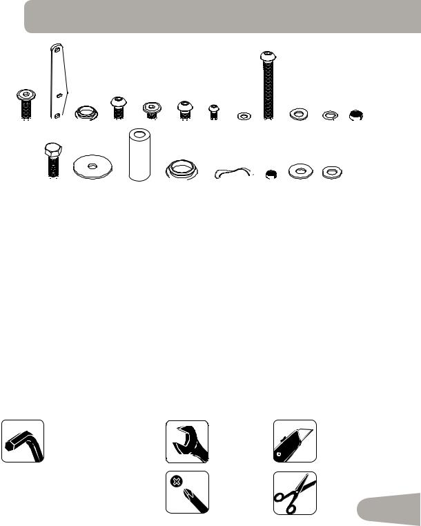
HARDWARE / TOOLs
A B
B C
C D
D E
E F
F G
G H
H I
I J K
J K
 L
L

M N O P
N O P Q
Q

 R
R
 S T
S T
Item |
Qty |
Description |
Item |
Qty |
Description |
|
|
|
|
|
|
A |
8 |
Flat Head Hex Screw, M8x1.25x20 |
K |
24 |
Lock Washer, M8 |
|
|
|
|
|
|
B |
2 |
Plate, Pedal |
L |
2 |
Lock Nut, M8 |
|
|
|
|
|
|
C |
6 |
Cap, Small |
M |
4 |
Hex Screw, M8x1.25x25 |
|
|
|
|
|
|
D |
8 |
Button Head Hex Screw, M8x1.25x20 |
N |
2 |
Wide Washer, 38mm |
|
|
|
|
|
|
E |
2 |
Flat Head Hex Screw, M8x1.25x14 |
O |
2 |
Sleeve |
|
|
|
|
|
|
F |
12 |
Button Head Hex Screw, M8x1.25x16 |
P |
4 |
Cap, Large |
|
|
|
|
|
|
G |
4 |
Button Head Hex Screw, M6x1.0x14 |
Q |
2 |
Wave Washer |
|
|
|
|
|
|
H |
4 |
Flat Washer, M6 |
R |
4 |
Lock Nut, M6 |
|
|
|
|
|
|
I |
2 |
Button Head Hex Screw, M8x1.25x70 |
S |
2 |
Wide Washer, M8 |
|
|
|
|
|
|
J |
14 |
Curved Washer, M8 |
T |
10 |
Flat Washer, M8 |
|
|
|
|
|
|
Tools
Included |
Not Included |
|
4 mm |
10 mm |
(recommended) |
6 mm |
||
6 mm (long) |
13 mm (x2) |
|
|
|
#2
7
ASSEMBLY
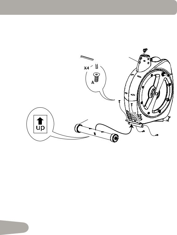
1. Attach Front Stabilizer to Frame
8

 6mm
6mm
5
8
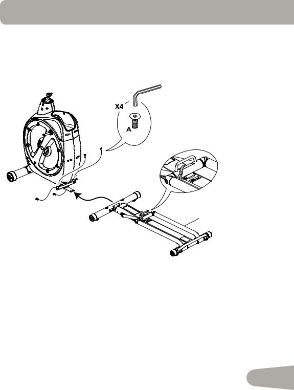
2. Attach Rail Assembly to Frame Assembly
NOTICE: Do not cut Shipping Zip-Tie until instructed. Do not fully tighten this hardware.
6mm
10
9
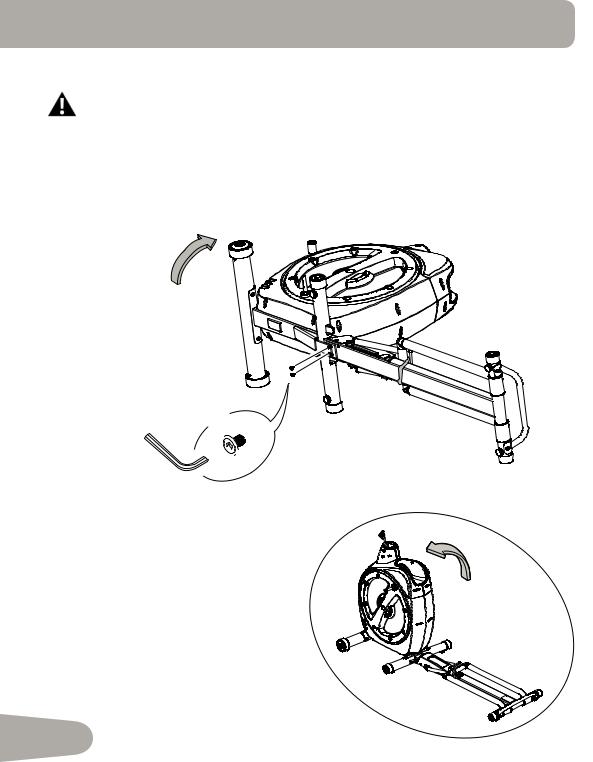
3. Tilt the Frame Assembly and Secure the Rail Assembly
The machine may be moved by one or more persons depending on their physical abilities and capacities. Make sure that you and others are all physically fit and able to move the machine safely.
NOTICE: This step requires at least two people. Fully tighten all hardware from previous steps.
X2
 E
E
6mm
10
4. Cut the Shipping Zip-Tie and Inspect the Rail Assembly
Note: Be sure the Incline is lowered on the Rail Assembly. If not, follow the procedure to release the Incline Assembly on page 32.
11
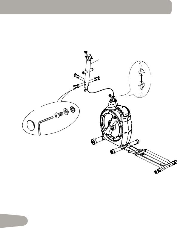
5. Connect the Console Mast
NOTICE: Align the clips on the cable connectors and make sure the connectors lock. Do not crimp Console Cable.
3
X6
K J
F
 C
C
6mm (long)
12
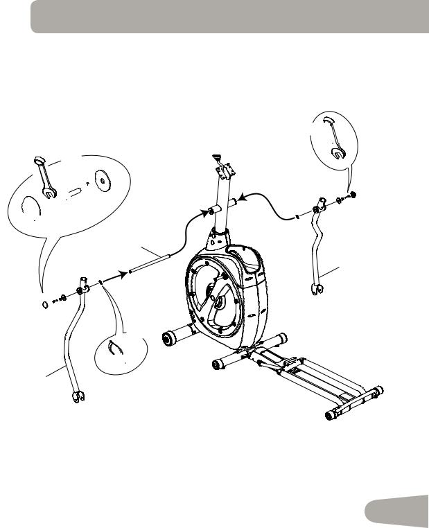
6. Attach Arm Pivot Rod and Lower Handlebar Arms to Frame Assembly
13 mm
X2
13 mm


 M
M
 K N
K N

 P
P
2
7
X2
 Q
Q
14
13
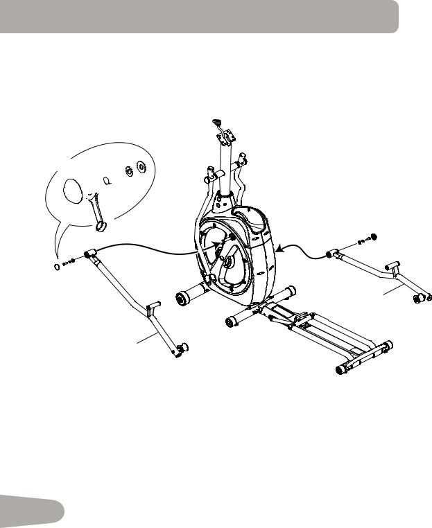
7. Attach Legs to Frame Assembly
X2


 K
K
 S
S


 M
M
P
13 mm |
9
12
14
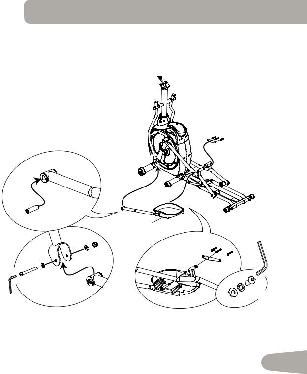
8. Attach Left Pedal to Frame Assembly
NOTICE: Repeat step on opposite side with the Right Pedal (Item 6).
O
13
T |
L |
|
|
|
B |
|
|
T |
|
|
6mm |
I |
|
|
|
|
|
|
|
6mm |
T |
K F |
X3 |
|
|
|
15

9. Attach and Adjust the Upper Handlebar Arms to Frame Assembly
NOTICE: To adjust the Upper Handlebar Arms, loosen the adjustment knob on the end. Fully tighten the adjustment knob to secure the Arm in the new position.
 Make sure the Upper Handlebar Arms are secure before you exercise.
16 |
5 |
|
X8
J
K
D
6mm
16
 Loading...