


Built-in Trim Kit
Installation Instructions
MA-TK8020**
MA-TK8020_AA_II_DE68-04476A-01_EN.indd 1 |
|
|
2017-06-01 6:16:02 |
|
|
||
|
|
|
|

<![endif]>Contents
Contents
Before you begin
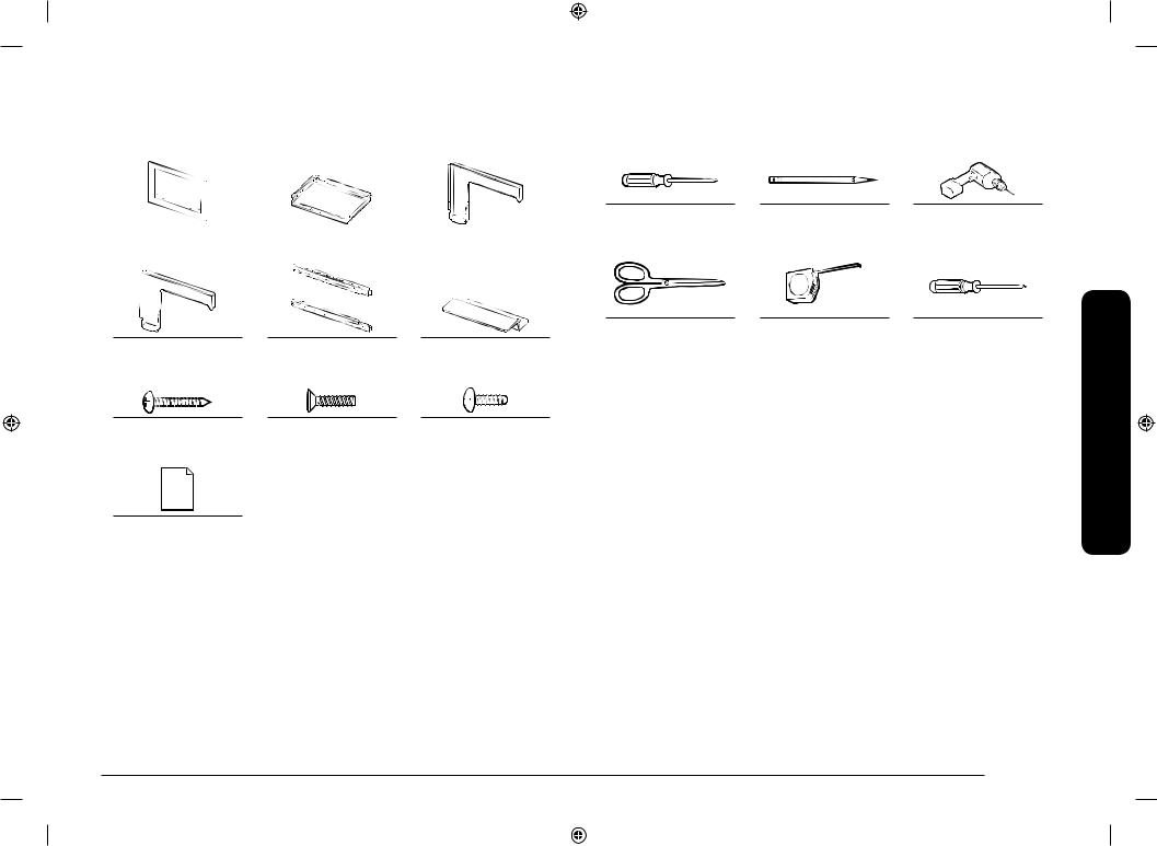
Parts included in the kits
Tools needed
Installation
2 English
Before you begin
2
Read these instructions completely and carefully.
IMPORTANT
3• Save these instructions for local inspector’s use.
• Observe all governing codes and coordinates.
3• Be sure to disconnect the plug of the microwave oven from the electrical outlet before installing the Builtin Kit. Remove the turntable from the oven cavity.
4• The kit includes metal parts, due caution should be used in handling and installation to avoid the possibility of injury.
•Do not remove permanently affixed labels, warnings or plates from the product. Doing so may void the warranty.
 WARNING
The electrical requirements for this oven are 115-120 volts AC, 15 amps or larger.
MA-TK8020_AA_II_DE68-04476A-01_EN.indd 2 |
|
|
2017-06-01 6:16:02 |
|
|
||
|
|
|
|
Parts included in the kits |
Tools needed |
|
|
|
|
|
|
|
|
|
Screwdriver |
Pencil |
Drill with 7/64 or #35 Drill |
|
|
|
|
|
|
|
bit |
Trim Frame (1 EA) |
|
Duct Base (1 EA) |
|
Duct Side (1 EA) |
|
||
|
|
|
|
||||
Scissors |
Tape measure |
T15H Torx driver |
Duct Rear (1 EA) |
Install Bracket (2 EA) |
Install hook |
Screw A |
Screw B |
Screw C |
(5/8” length) (12 EA) |
(15/32” length) (4 EA) |
(25/64” length) (9 EA) |
Template (1 EA)
English 3
<![endif]>kits the in included Parts
MA-TK8020_AA_II_DE68-04476A-01_EN.indd 3 |
|
|
2017-06-01 6:16:03 |
|
|
||
|
|
|
|
<![endif]>Installation
Installation
STEP 1 |
STEP 2 |
|
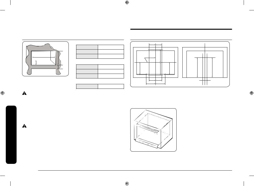
CUTOUT DIMENSIONS |
|
|
P5 |
A |
A |
P6 |
|
|
Height |
16 3/4" ± 1/16" |
|
|
||||
|
|
|
|
|
|
|
||
|
Width |
25 1/2" ± 1/16" |
CENTER |
|
|
|
||
Width |
Depth |
21 1/2" ± 1/16" |
|
C |
|
|||
LINE |
|
|
|
|||||
Height |
|
|
|
|
|
|||
|
|
|
|
|
|
|||
Depth |
TRIM DIMENSIONS |
|
|
|
|
|
|
|
|
|
|
|
|
|
|
|
|
3" min |
Height |
20 1/16" ± 1/64" |
|
D |
|
|
C |
D |
Electric Heat |
Width |
29 3/4" ± 1/64" |
|
|
|
|||
|
|
|
|
|
|
|||
Source Model |
|
|
|
|
|
|
||
Depth |
1 1/4" ± 1/64" |
|
|
|
|
|
|
|
|
|
|
|
A |
A |
|
||
|
TRIM WEIGHT |
|
|
|
P2 |
P3 |
||
|
|
|
|
P1 |
B |
B |
P4 |
|
|
Net Weight |
13.23 lb |
|
|
|
|||
|
|
|
|
|
|
|
||
|
|
|
A : 5 1/8" (130 mm) |
|
|
|||
WARNING |
|
|
B : 6 7/8" (175 mm) |
|
|
|||
To avoid risk of electrical shock, personal injury, or death: |
|
C : 9 3/8" (238.5 mm) |
|
|
||||
• Before drilling into the wall, note where electrical outlets are and where |
D : 8 23/32" (221.3 mm) |
|
||||||
electrical wire might be concealed behind the wall. YOU COULD GET AN |
|
|||||||
|
|
|
|
|
|
|||
ELECTRICAL SHOCK if you contact electrical wire with the drill bit. |
|
|
|
|
|
|
||
• Locate and disconnect the power to any electrical circuits that could be |
|
|
|
|
|
|
||
affected by installing this oven. |
|
|
|
|
|
|
|
|
IF YOU DO NOT DISCONNECT THE POWER, YOU COULD GET AN ELECTRICAL SHOCK. |
|
|
|
|
|
|
||
WARNING |
|
|
|
P5 |
|
|
|
|
|
|
|
|
|
P6 |
|
|
|
To avoid personal injury, wear gloves when handling the metal parts. Parts are |
|
|
|
|
|
|||
|
|
|
|
|
|
|||
sharp and can cause cuts and abrasions. |
|
|
|
|
|
P7 P8 |
|
|
|
|
|
|
|
|
|
||
|
|
|
P1 |
P2 |
P3 P4 |
|
|
|
P7 |
P8 |
F |
F |
E |
E |
E : 7/8" (23 mm)
F : 16 1/8" (409.5 mm)
1.Folding the underline of Template and match with the cabinet edge line, mark 6holes at bottom.
(P1,2,3,4,7,8)
2.Folding the topline of Template and match with the cabinet edge line, mark 2holes at top. (P5,6)
3.Then drill a pilot hole at the 8positions using 7/64 or #35 drill bit.
4 English
MA-TK8020_AA_II_DE68-04476A-01_EN.indd 4 |
|
|
2017-06-01 6:16:04 |
|
|
||
|
|
|
|

4. Tight 2 screws together on the |
STEP 4 |
Install hook by using provided |
|
SCREW A. (2 EA) |
|
NOTE |
|
You may not be assembled when using |
|
the thicker Drill bit. |
|
1. Place oven on the Duct Base.

 Duct Base
STEP 3
5. Remove 4 screws from the lower right and left side of outer panel.
2.Tight 2 screws together on the back side with Duct base by using provided SCREW C. (2 EA)
3.Tight 2 screws together on the right side with Duct base by using provided SCREW C. (2 EA)
<![if ! IE]><![endif]>Installation
English 5
MA-TK8020_AA_II_DE68-04476A-01_EN.indd 5 |
|
|
2017-06-01 6:16:04 |
|
|
||
|
|
|
|
 Loading...