


Owner’s manual
Manuel de l’utilisateur
Manual de Instrucciones
RSP-1098
Surround Sound Processor
Processeur de Son Surround
Procesador De Sonido Envolvente
|
|
SURROUND SOUND PROCESSOR |
RSP-1098 |
|
|
STANDBY |
ZONE 2 |
|
|
|
|
|
FUNCTION |
|
|
VOLUME |
|
|
PUSH |
|
|
|
|
PATH |
SPEAKER |
MODE |
DISPLAY |
MENU |
MUTE |
RSP-1098 |
2 |
||||||||||||||||||||||||||||
|
|
|
|
|
|
|
|
|
|
|
|
|
|
|
|
|
|
|
|
|
|
|
|
|
|
|
|
|
|
|
|
|
|
|
|
|
|
|
|
|
|
|
|
|
|
|
|
|
|
|
|
|
|
|
|
|
|
|
|
|
|
|
|
|
|
|
|
|
|
|
|
|
|
|
|
|
|
|
|
|
|
|
|
|
|
|
|
|
|
|
|
|
|
|
|
|
|
|
|
|
|
|
|
|
|
|
|
|
|
|
|
|
|
|
|
|
|
|
|
|
|
|
|
|
|
|
|
|
|
|
|
|
|
|
|
|
|
|
|
|
|
|
|
|
|
|
|
|
|
|
|
|
|
|
|
|
|
|
|
|
|
|
|
|
|
|
|
|
|
|
|
|
|
|
|
|
|
|
|
|
|
|
|
|
|
|
|
|
|
|
|
|
|
|
|
|
|
|
|
|
|
|
|
|
|
|
|
|
|
|
|
|
|
|
|
|
|
|
|
|
|
|
|
|
|
|
|
|
|
|
|
|
|
|
|
|
|
|
|
|
|
|
|
|
|
|
|
|
|
|
|
|
|
|
|
|
|
|
|
|
|
|
|
|
|
|
|
|
|
|
|
|
|
|
|
|
|
|
|
|
|
|
|
|
|
|
|
|
|
|
|
|
|
|
|
|
|
|
|
|
|
|
|
|
|
|
|
|
|
|
|
|
|
|
|
|
|
|
|
|
|
|
|
|
|
|
|
|
|
|
|
|
|
|
|
|
|
|
|
|
|
|
|
|
|
|
|
|
|
|
|
|
|
|
|
|
|
|
|
|
|
|
|
|
|
|
|
|
|
|
|
|
|
|
|
|
|
|
|
|
|
|
|
|
|
|
|
|
|
|
|
|
|
|
|
|
|
|
|
|
|
|
|
|
|
|
|
|
|
|
|
|
|
|
|
|
|
|
|
|
|
|
|
|
|
|
|
|
|
|
|
|
|
|
|
|
|
|
|
|
|
|
|
|
|
|
|
|
|
|
|
|
|
|
|
|
|
|
|
|
|
|
|
|
|
|
|
|
|
|
|
|
|
|
|
|
|
|
|
|
|
|
|
|
|
|
|
|
|
|
|
|
|
|
|
|
|
|
|
|
|
|
|
|
|
|
|
|
|
|
|
|
|
|
|
|
|
|
|
|
|
|
|
|
|
|
|
|
|
|
|
|
|
|
|
|
|
|
|
|
|
|
|
|
|
|
|
|
|
|
|
|
|
|
|
|
|
|
|
|
|
|
|
|
|
|
|
|
|
|
|
|
|
|
|
|
|
|
|
|
|
|
|
|
|
|
|
|
|
|
|
|
|
|
|
|
|
|
|
|
|
|
|
|
|
|
|
|
|
|
|
|
|
|
|
|
|
|
|
|
|
|
|
|
|
|
|
|
|
|
|
|
|
|
|
|
|
|
|
|
|
|
|
|
|
|
|
|
|
|
|
|
|
|
|
|
|
|
|
|
|
|
|
|
|
|
|
|
|
|
|
|
|
|
|
|
|
|
|
|
|
|
|
|
|
|
|
|
|
|
|
|
|
|
|
|
|
|
|
|
|
|
|
|
|
|
|
|
|
|
|
|
|
|
|
|
|
|
|
|
|
|
|
|
|
|
|
|
|
|
|
|
|
|
|
|
|
|
|
|
|
|
|
|
|
|
|
|
|
|
|
|
|
|
|
|
|
|
|
|
|
|
|
|
|
|
|
|
|
|
|
|
|
|
|
|
|
|
|
|
|
|
|
|
|
|
|
|
|
|
|
|
|
|
|
|
|
|
|
|
|
|
|
|
|
|
|
|
|
|
|
|
|
|
|
|
|
|
|
|
|
|
|
|
|
|
|
|
|
|
|
|
|
|
|
|
|
|
|
|
|
|
|
|
|
|
|
|
|
|
|
|
|
|
|
|
|
|
|
|
|
|
|
|
|
|
|
|
|
|
|
|
|
|
|
|
|
|
|
|
|
|
|
|
|
|
|
|
|
|
|
|
|
|
|
|
|
|
|
|
|
|
|
|
|
|
|
|
|
|
|
|
|
|
|
|
|
|
|
|
|
|
|
|
|
|
|
|
|
|
|
|
|
|
|
|
|
|
|
|
|
|
|
|
|
|
|
|
|
|
|
|
|
|
|
|
|
|
|
|
|
|
|
|
|
|
|
|
|
|
|
|
|
|
|
|
|
|
|
|
|
|
|
|
|
|
|
|
|
|
|
|
|
|
|
|
|
|
|
|
|
|
|
|
|
|
|
|
|
|
|
|
|
|
|
|
|
|
|

|
3 |
Notice |
Important Safety Instructions |
The COMPUTER I/O connection should be handled by authorized person only.
FCC Information
This equipment has been tested and found to comply with the limits for a Class B digital device, pursuant to Part 15 of the FCC Rules. These limits are designed to provide reasonable protection against harmful interference in a residential installation. This equipment generates, uses and can radiate radio frequency energy and, if not installed and used in accordance with the instruction, may cause harmful interference to radio communications.
However, there is no guarantee that interference will not occur in a particular installation. If this equipment does cause harmful interference to radio or television reception, which can be determined by turning the equipment off and on, the user is encouraged to try to correct the interference by one or more of the following measures:
•Reorient or relocate the receiving antenna.(TV, radio, etc.)
•Increase the separation between the equipment and receiver
•Connect the equipment to an outlet on circuit different from that to which the receiver is connected.
•Consult the dealer or an experienced radio/TV technician for additional help.
Caution
This device complies with part 15 of the FCC Rules operation is subject to the following to conditions: (1) This device may not cause harmful interference, and (2) this device must accept any interference received, including interference that may cause undesired operation.
WARNING: There are no user serviceable parts inside. Refer all servicing to qualified service personnel.
WARNING: To reduce the risk of fire or electric shock, do not expose the unit to moisture or water. Do not allow foreign objects to get into the enclosure. If the unit is exposed to moisture, or a foreign object gets into the enclosure, immediately disconnect the power cord from the wall. Take the unit to a qualified service person for inspection and necessary repairs.
Read all the instructions before connecting or operating the component. Keep this manual so you can refer to these safety instructions.
Heed all warnings and safety information in these instructions and on the product itself. Follow all operating instructions.
Clean the enclosure only with a dry cloth or a vacuum cleaner.
You must allow 10 cm or 4 inches of unobstructed clearance around the unit. Do not place the unit on a bed, sofa, rug, or similar surface that could block the ventilation openings. If the unit is placed in a bookcase or cabinet, there must be ventilation of the cabinet to allow proper cooling.
Keep the component away from radiators, heat registers, stoves, or any other appliance that produces heat.
The unit must be connected to a power supply only of the type and voltage specified on the rear panel. (USA: 115 V/60Hz, EC: 230V/50Hz)
Connect the component to the power outlet only with the supplied power supply cable or an exact equivalent. Do not modify the supplied cable. Do not defeat grounding and/or polarization provisions. The cable should be connected to a 2-pin polarized wall outlet, matching the wide blade of the plug to the wide slot of the receptacle. Do not use extension cords.
Do not route the power cord where it will be crushed, pinched, bent, exposed to heat, or damaged in any way. Pay particular attention to the power cord at the plug and where it exits the back of the unit.
The power cord should be unplugged from the wall outlet during a lightning storm or if the unit is to be left unused for a long period of time.
Immediately stop using the component and have it inspected and/or serviced by a qualified service agency if:
•The power supply cord or plug has been damaged.
•Objects have fallen or liquid has been spilled into the unit.
•The unit has been exposed to rain.
•The unit shows signs of improper operation
•The unit has been dropped or damaged in any way
RSP-1098 |
4 |
Information FCC
Cet appareil a été testé afin de vérifier sa conformité avec les normes minima des appareils numériques de classe B, suivant l’article 15 des normes FCC. Ces normes garantissent une protection suffisante contre les interférences, dans le cadre d’une utilisation domestique. Cet appareil génère, utilise et peut rayonner des fréquences radio et peut, s’il n’est pas utilisé selon les conseils prodigués dans ce manuel d’utilisation, causer des interférences avec les communications radio.
Il n’y a cependant aucune garantie que ces interférences n’interviennent dans certaines installations. Si vous notez la présence de parasites sur la radio ou la télévision (détectées par la mise sous et hors tension de l’appareil), vous pouvez essayer d’éliminer ces interférences en essayant une des procédures suivantes:
•Réorientez ou déplacez l’antenne de réception (TV, radio, etc.)
•Augmentez l’éloignement physique entre le récepteur en cause et l’appareil.
•Branchez les autres maillons sur une prise secteur différente de celle sur laquelle est branché le récepteur.
•Consultez votre revendeur, ou un technicien spécialiste de ces questions de réception radio/TV.
Attention: Cet appareil répond aux normes de l’article 15 de la FCC sous les conditions suivantes: 1) Cet appareil ne doit pas causer d’interférence très sensible. 2) Cet appareil doit pouvoir accepter n’importe quelle interférence externe, y compris celles dues à une utilisation fortuite.
Notice
Conseils de Sécurité
ATTENTION: Il n’y a à l’intérieur aucune pièce susceptible d’être modifiée par l’utilisateur. Adressez-vous impérativement à une personne qualifiée.
ATTENTION: Prenez garde à ce qu’aucun objet ou liquide ne tombe à l’intérieur de l’appareil par ses orifices de ventilation; Si l’appareil est exposé à l’humidité ou si un objet tombe à l’intérieur, couper immédiatement l’alimentation secteur de tous les appareils. Débrancher l’appareil des autres maillons, et adressez-vous immédiatement et uniquement à une personne qualifiée et agréée.
Tous les conseils de sécurité et d’installation doivent être lus avant de faire fonctionner l’appareil. Conservez soigneusement ce livret pour le consulter à nouveau pour de futures références.
Tous les conseils de sécurité doivent être soigneusement respectés. Suivez les instructions. Respectez les procédures d’installation et de fonctionnement indiquées dans ce manuel.
L’appareil doit être nettoyé uniquement avec un chiffon sec ou un aspirateur.
L’appareil doit être placé de telle manière que sa propre ventilation puisse fonctionner, c’est-à-dire avec un espace libre d’une dizaine de centimètres autour de lui. Il ne doit pas être posé sur un fauteuil, un canapé, une couverture ou toute autre surface susceptible de boucher ses ouïes d’aération; ou placé dans un meuble empêchant la bonne circulation d’air autour des orifices d’aération.
Cet appareil doit être placé loin de toute source de chaleur, tels que radiateurs, chaudières, bouches de chaleur ou d’autres appareils (y compris amplificateurs de puissance) produisant de la chaleur.
Cet appareil doit être branché sur une prise d’alimentation secteur, d’une tension et d’un type conformes à ceux qui sont indiqués sur la face arrière de l’appareil (Europe, 230 V/50 Hz).
Brancher l’appareil uniquement grâce au cordon secteur fourni, ou à un modèle équivalent. Ne pas tenter de modifier ou changer la prise. Notamment, ne pas tenter de supprimer la prise de terre si celle-ci est présente. Ne pas utiliser de cordon rallonge.
Prendre garde à ce que ce cordon d’alimentation ne soit pas pincé, écrasé ou détérioré sur tout son trajet, à ce qu’il ne soit pas mis en contact avec une source de chaleur. Vérifier soigneusement la bonne qualité des contacts, à l’arrière de l’appareil comme dans la prise murale.
Si l’appareil ne doit pas être utilisé pendant une longue période, la prise secteur sera débranchée.
L’appareil doit être immédiatement éteint, débranché puis retourné au service après-vente agréé dans les cas suivants:
•Un objet est tombé, ou du liquide a coulé à l’intérieur de l’appareil.
•L’appareil a été exposé à la pluie.
•L’appareil ne fonctionne pas normalement, ou ses performances sont anormalement limitées.
•L’appareil est tombé, ou le coffret est endommagé.
Le branchement repéré COMPUTER I/O ne concerne que des techniciens agréés uniquement.
5
Información de la FCC
Este aparato ha sido debidamente probado y satisface los límites de funcionamiento correspondientes a un componente digital de Clase B especificados en el Apartado 15 de la Normativa de la FCC. Dichos límites han sido diseñados para proporcionar una protección razonable frente a interferencias en instalaciones domésticas. Este equipo genera y puede radiar energía de radiofrecuencia y en el caso de que no sea instalado y utilizado siguiendo las instrucciones suministradas por el fabricante, puede causar interferencias en comunicaciones de radio o televisión.
No obstante, no se garantiza que las citadas interferencias no puedan tener lugar en una instalación particular. Si este aparato interfiere la recepción de programas de radio o televisión, lo que puede determinarse activándolo y desactivándolo, intente corregir la interferencia aplicando una o varias de las siguientes medidas.
•Reoriente o reubique la antena de recepción.
•Aumente la separación entre el aparato y el sintonizador del televisor.
•Conecte el aparato a un enchufe perteneciente a un circuito eléctrico diferente.
•En caso de que tenga cualquier otra duda, consulte a su distribuidor autorizado de productos Rotel o a un técnico experimentado televisión o radio.
Precaución: Este aparato cumple con el Apartado 15 de la Normativa de la FCC y su funcionamiento está sujeto a las siguientes condiciones: (1) Este aparato no debe provocar interferencias perjudiciales, y (2) debe aceptar cualquier interferencia que reciba, incluyendo aquellas que puedan afectar negativamente a su funcionamiento.
Nota Importante
La conexión COMPUTER I/O debería ser manipulada únicamente por personal autorizado.
Instrucciones Importantes Relacionadas con la Seguridad
ADVERTENCIA: No hay componentes manipulables por el usuario en el interior del aparato. Cualquier operación de mantenimiento debe ser llevada a cabo por personal cualificado.
ADVERTENCIA: Para reducir el riesgo de que se produzca un incendio o una descarga eléctrica, no exponga el RSP-1098 al aguaolahumedad.Nopermitaqueningúnobjetoextrañopenetre enelinteriordelaparato.Sielaparatoestáexpuestoalahumedad o algún objeto extraño penetra en su interior, desconecte inmediatamente el cable de alimentación de la red eléctrica. En caso de que fuera necesario, envíe el aparato a un especialista cualificado para su inspección y posterior reparación.
Lea todas las instrucciones del presente manual antes de conectar o hacer funcionar el RSP-1098. Conserve este manual cerca de usted para el caso de que necesite revisar las instrucciones de seguridad que se indican a continuación.
Tenga siempre en mente las advertencias y la información relativa a seguridad que figuran tanto en estas instrucciones como en el propio aparato. Siga al pie de letra todas las instrucciones relacionadas con el funcionamiento del mismo.
Limpie el exterior del RSP-1098 únicamente con una gamuza seca o un aspirador.
Debería dejar unos 10 centímetros de espacio libre alrededor del aparato. No coloque nunca el RSP-1098 sobre una cama, un sofá, una alfombra o una superficie similar susceptible de bloquear las ranuras de ventilación. Si el RSP-1098 está ubicado en la estantería de una librería o un mueble, debe haber suficiente espacio a su alrededor y ventilación en el mueble para permitir una refrigeración adecuada.
Mantenga el RSP-1098 alejado de radiadores, estufas, cocinas o de cualquier otra instalación que produzca calor.
El RSP-1098 debe ser conectado únicamente a una fuente de alimentación del tipo y tensión especificados en su panel posterior (230 V/50 Hz para los países de la Comunidad Económica Europea y 115 V/60 Hz para Estados Unidos).
Conecte el RSP-1098 a una toma de corriente eléctrica únicamente a través del cable de alimentación de dos clavijas polarizado suministrado de serie o un equivalente exacto del mismo. No modifique de ningún modo dicho cable. No intente desactivar los terminales destinados a la conexión a tierra o polarización. El cable debería ser conectado a una toma de corriente eléctrica de dos terminales que se adapten perfectamente a las clavijas del cable de alimentación del RSP-1098. No utilice ningún tipo de cable de extensión.
No coloque el cable de alimentación en lugares en que pueda ser aplastado, perforado, doblado en ángulos críticos, expuesto al calor o dañado de algún modo. Preste particular atención al punto de unión entre el cable y la toma de corriente y también a la ubicación de esta última en el panel posterior del aparato.
El cable de alimentación debería desconectarse de la red eléctrica cuando el aparato no vaya a ser utilizado durante un largo período de tiempo (por ejemplo durante las vacaciones de verano).
Deje inmediatamente de utilizar el RSP-1098 y envíelo a un servicio técnico cualificado para su inspección/reparación si:
•El cable de alimentación o alguna clavija del mismo ha sido dañado.
•Han caído objetos o se ha derramado líquido en el interior del aparato.
•El aparato ha sido expuesto a la lluvia.
•El aparato muestra signos de funcionamiento inadecuado.
•El aparato ha sido golpeado o dañado de algún modo.
RSP-1098 |
6 |
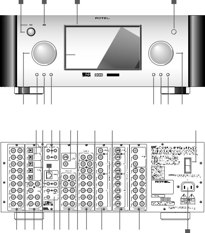
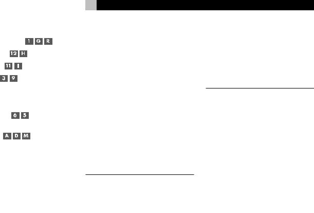
1:Front and Rear Panels Faces Avant et Arrière Paneles Frontal y Posterior
SURROUND SOUND PROCESSOR RSP-1098
STANDBY |
ZONE 2 |
|
|
FUNCTION |
VOLUME |
|
PUSH |
|
PATH SPEAKER MODE |
DISPLAY MENU |
MUTE |
|
|
|
|
|
|
|
|
|
|
|
|
|
|
|
|
|
|
|
|
|
|
|
|
|
|
|
|
|
|
|
|
|
|
|
|
|
|
|
|
|
|
|
|
|
|
|
|
|
|
|
|
|
|
|
|
|
|
|
|
|
|
|
|
|
|
|
|
|
|
|
|
|
|
|
|
|
|
|
|
|
|
|
|
|
|
|
|
|
|
|
|
|
|
|
|
|
|
|
|
|
|
|
|
|
|
|
|
|
|
|
|
|
|
|
|
|
|
5 |
|
6 |
|
7 |
|
8 |
|
|
|
|
|
|
|
|
|
|
|
|
|
|
|
|
|
|
|
|
|
|
|
|
|
|
|
|
|
|
|
9 |
|
10 |
|
11 |
|
12 |
|
|
|
|||||
|
|
|
|
|
|
|
|
|
|
|
|
|
|
|
|
|
|
|
|
|
|
|
|
|
|
|
|
|
|
|
|
|
|
|
|
|
|
|
|
|
|
|
||||||||||||||
|
13 |
|
|
|
|
|
14 |
|
15 |
|
|
16 |
|
17 |
18 |
19 |
|
20 |
21 |
22 |
23 |
24 |
25 |
|
|
|
|
|
|
26 |
||||||||||||||||||||||||||
|
|
|
|
|
|
|
|
|
|
|
|
|
|
|
|
|
|
|
|
|
|
|
|
|
|
|
|
|
|
|
|
|
|
|
|
|
|
|
|
|
|
|
|
|
|
|
|
|
|
|
|
|
|
|
|
|
|
|
|
|
|
|
|
|
|
|
|
|
|
|
|
|
|
|
|
|
|
|
|
|
|
|
|
|
|
|
|
|
|
|
|
|
|
|
|
|
|
|
|
|
|
|
|
|
|
|
|
|
|
|
|
|
|
|
|
|
|
|
|
|
|
|
|
|
|
|
|
|
|
|
|
|
|
|
|
|
|
|
|
|
|
|
|
|
|
|
|
|
|
|
|
|
|
|
|
|
|
|
|
|
|
|
|
|
|
|
|
|
|
|
|
|
|
|
|
|
|
|
|
|
|
|
|
|
|
|
|
|
|
|
|
|
|
|
|
|
|
|
|
|
|
|
|
|
|
|
|
|
|
|
|
|
|
|
|
|
|
|
|
|
|
|
|
|
|
|
|
3 |
ZONE2 |
|
S-VIDEO |
|
POWER |
1 |
2 |
|
ON |
40 |
COMPOSITE |
|
OFF |
|
SURROUND SOUND PROCESSOR |
|
MODEL NO: RSP-1098 |
POWER CONSUMPTION: 70 WATTS
27 |
|
28 |
|
29 |
|
30 |
|
31 |
|
32 |
|
33 |
|
34 |
|
35 |
|
36 |
|
37 |
|
38 |
39 |
7
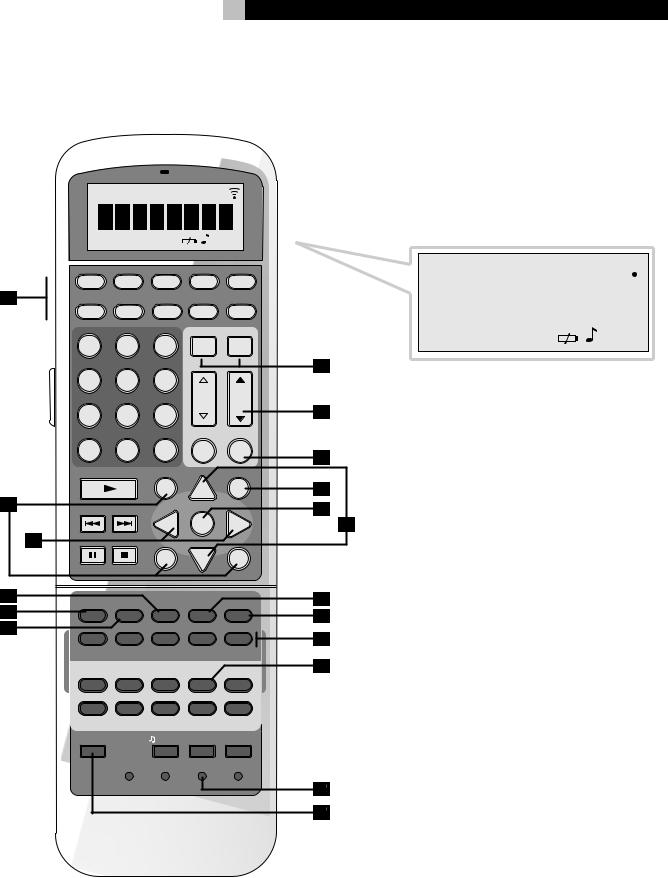
2:RR-1050 Remote Télécommande RR-1050 Mando a Distancia RR-1050
|
CLONE REPT TRANSMITTER LOADING RECEIVER |
||||
|
EDIT |
LEARN |
|
WAITING |
|
|
AUD |
CD |
TUN |
TAPE |
EXT |
A |
|
DEVICE / INPUT |
|
||
|
V1 |
V2 |
V3 |
V4 |
V5 |
|
|
|
|
POWER |
|
|
1 |
2 |
3 |
ON |
OFF |
|
4 |
5 |
6 |
|
|
|
|
|
|
CH |
VOL |
|
7 |
8 |
9 |
|
|
|
|
|
|
MACRO |
|
|
+10 |
0 |
X |
M |
MUTE |
|
FRQ DIRECT |
GUIDE |
|
MENU |
|
|
|
|
C |
UP |
M |
B |
|
|
|
|
|
TUNE |
PRESET |
CTR |
|
OSD |
|
|
|
|
|
||
|
|
|
- |
ENT |
+ |
C |
FM MONO |
BAND |
SEARCH – |
|
SEARCH + |
|
|
|
S |
DWN |
R |
|
|
|
|
||
|
|
|
SUB |
|
SUR |
D |
CD |
|
|
|
|
E |
DISC 1 |
DISC 2 |
DISC 3 |
DISC 4 |
DISC 5 |
EQ |
DYN |
REC |
ZONE |
SUR+ |
|
F |
|
|
|
|
|
|
2CH |
PL C |
PL M |
5CH |
7CH |
|
PROG |
RANDOM |
REPEAT |
DISC- |
DISC+ |
|
DISPLAY |
AUDIO |
ANGLE |
SBTITLE |
ZOOM |
|
DISP |
TAPE2 |
PHONO |
TONE |
D-SLT |
|
RESUME |
REPEAT |
A -B |
GOTO |
SLOW |
|
SCAN |
PTY |
P-TUN |
TP |
TA |
|
INPUT 1 |
INPUT 2 |
INPUT 3 |
TV/VCR |
RECORD |
|
DVD |
|
|
|
|
|
POWER |
|
/ CLONE |
EDIT |
LEARN |
|
|
CLEAR |
LANG |
PRELOAD |
RESET |
|
|
|
PAGE 1/2 |
|
|
CLONE REPT TRANSMITTER LOADING RECEIVER 
|
|
|
|
|
|
|
|
|
|
|
|
|
|
|
|
|
|
|
|
|
|
|
|
|
|
|
|
|
|
|
|
|
|
|
|
|
|
|
|
|
|
|
|
|
|
|
|
|
|
|
|
|
|
|
|
|
|
|
|
|
|
|
|
|
|
|
|
|
|
|
|
|
|
|
|
|
|
|
|
|
|
|
|
|
|
|
|
|
|
|
|
|
|
|
|
|
|
|
|
|
|
|
|
|
|
|
|
|
|
|
|
|
|
|
|
|
|
|
|
|
|
|
|
|
|
EDIT LEARN |
|
|
|
|
|
|
|
|
|
|
WAITING |
||||||
G
H
I
J
K
L
M
N
O
P
Q
R
RSP-1098 |
8 |
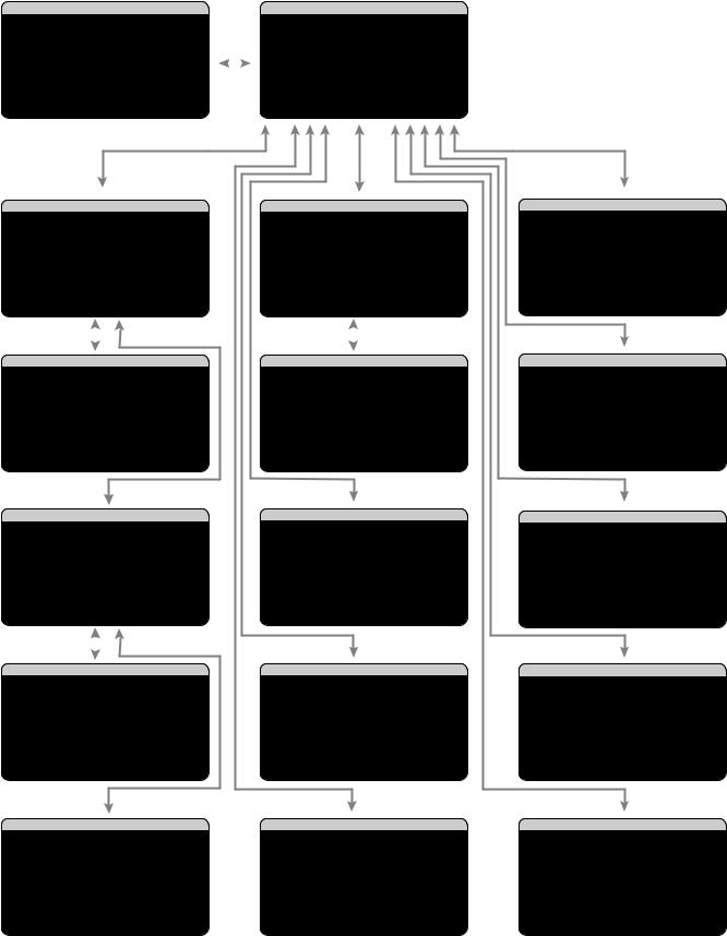
3:On-Screen Display/TFT Screen Menus Menus On-Screen Display/Ecran TFT
Sistema de Visualización en Pantalla/Menús de la Pantalla TFT
SYSTEM |
STATUS |
|
|
MAIN |
MENU |
||||||
LISTEN:Tuner |
|
|
|
|
|
|
|
|
|||
VID INPUT:Video |
1 |
|
|
|
|
INPUT |
SPEAKER |
||||
RECORD:Source |
|
|
|
|
|
|
DELAY |
TEST TONE |
|||
MODE:Dolby |
Digital |
|
|
SUB SETUP |
ZONE 2 |
||||||
INPUT:Coaxial 2 |
|
|
DISPLAY |
CONTOUR |
|||||||
VOLUME:65 |
|
|
|
|
|
|
|
OTHER |
DEFAULT |
||
ZONE 2:Off |
|
|
|
|
|
|
|
|
|
||
SPEAKERS: |
FL |
|
CNT |
|
SUB |
|
FR |
|
|
EXIT |
|
|
SL |
|
CB1 |
|
CB2 |
SR |
|
|
|
|
|
|
INPUT SETUP |
|
|
|
|
SPEAKER SETUP |
|
|||||
LISTEN:CD |
|
|
|
|
|
|
|
|
||||
VID INPUT:Video 1 |
|
|
|
|
FRONT:Large |
|
||||||
INPUT LABEL:_______ |
|
|
|
CENTER:Large |
|
|||||||
|
INPUT:Coaxial 2 |
|
SURROUND:Large |
|
||||||||
CINEMA EQ:Off |
|
|
CENTER BACK:Large1 |
|
||||||||
12V TRIGGER:1 |
|
|
SUBWOOFER:Yes |
|
||||||||
DEFAULT MODE:Dolby 3 Stereo |
|
ADVANCED:Enter |
|
|||||||||
GROUP DELAY:200ms |
|
|
|
|
|
|
|
|
||||
MAIN |
MENU |
|
|
|
|
|
MAIN |
MENU |
|
|
||
|
|
|
|
|
|
|
|
|
|
|
||
|
|
|
|
|
|
|
|
|
||||
|
|
|
|
|
|
|
|
|
||||
|
INPUT SETUP |
|
|
|
ADV |
SPEAKER SETUP |
||||||
|
LISTEN: |
|
|
|
|
|
|
|
|
|||
|
Multi Input |
|
|
|
|
|
|
|||||
VID INPUT:Video 1 |
|
|
|
SPEAKER:Front |
|
|||||||
INPUT LABEL:_______ |
|
|
CROSSOVER:100Hz |
|
||||||||
12V TRIGGER:1 |
|
|
|
|
DOLBY:Small |
|
||||||
|
|
|
|
DTS:Small |
|
|||||||
LFE REDIRECT:On |
|
|
STEREO/MPEG:Large |
|
||||||||
|
|
|
|
|
|
|
|
|
MUSIC:Small |
|
||
MAIN |
MENU |
|
|
|
|
|
SPEAKER SETUP MENU |
|
||||
|
INPUT SETUP |
|
|
|
SUBWOOFER SETUP |
|
||||||
LISTEN:CD |
|
|
|
CROSSOVER:100hZ |
|
|||||||
VID INPUT:Video 1 |
|
|
|
|
||||||||
INPUT LABEL:_______ |
|
|
DOLBY DIGITAL: |
0dB |
|
|||||||
|
INPUT:Coaxial |
2 |
|
DOLBY |
PL II: |
0dB |
|
|||||
CINEMA EQ:Off |
|
|
|
|
DTS: |
0dB |
|
|||||
12V TRIGGER:1 |
|
|
STEREO/MPEG:+ 2dB |
|
||||||||
DEFAULT MODE: |
Dolby PLII Cinema |
|
|
MUSIC: |
Off |
|
||||||
GROUP DELAY:200mS |
|
|
MULTI |
INPUT:- 2dB |
|
|||||||
MAIN |
MENU |
|
|
|
|
|
|
|
|
|
|
|
OPTION |
|
|
|
|
|
MAIN |
MENU |
|
|
|||
|
|
|
|
TEST |
TONE |
|
||||||
|
|
|
|
|
|
|||||||
DOLBY PRO LOGIC |
II |
|
|
|
||||||||
|
|
|
|
|
|
|
|
|
LEFT:+ |
1dB |
|
|
|
MODE:Music |
|
|
|
CENTER:- 1dB |
|
||||||
OPTIONAL PARAMETERS |
|
|
RIGHT:+ |
2dB |
|
|||||||
R SURROUND:+ 5dB |
|
|||||||||||
PANORAMA:Off |
|
|
R |
CTR |
BACK:+ |
2dB |
|
|||||
DIMENSION:3 |
|
|
L |
CTR |
BACK:+ |
2dB |
|
|||||
CENTER WIDTH:0 |
|
|
L SURROUND:+ 4dB |
|
||||||||
INPUT |
SETUP |
|
|
MENU |
|
|
SUBWOOFER:+ 9dB |
|
||||
|
|
|
|
|
|
|
|
|
|
|||
|
|
|
|
|
|
|
MAIN |
MENU |
|
|
||
|
DTS |
Neo:6 |
|
|
|
|
DELAY |
SETUP |
|
|||
|
|
|
|
|
|
|
|
|
LEFT: 12ft |
3.6m |
||
|
MODE:Cinema |
|
|
|
CENTER: 11ft |
3.3m |
||||||
|
|
|
|
|
|
|
|
|
RIGHT: 11ft |
3.3m |
||
|
|
|
|
|
|
|
R |
SURROUND: |
6ft |
1.8m |
||
|
|
|
|
|
|
|
R |
CTR |
BACK: |
8ft |
2.4m |
|
|
|
|
|
|
|
|
L |
CTR |
BACK: |
9ft |
2.7m |
|
|
|
|
|
|
|
|
L |
SURROUND: |
5ft |
1.5m |
||
INPUT |
SETUP |
|
|
MENU |
|
|
SUBWOOFER: |
5ft |
1.5m |
|||
|
|
|
|
|
|
|
|
|
|
|||
|
|
|
|
|
|
|
MAIN |
MENU |
|
|
||
CONTOUR SETUP
SPEAKER:Front
DEFEAT:On
HF CONTOUR:+5
LF CONTOUR: 0
MAIN MENU
DISPLAY OPTIONS
DISPLAY SOURCE:Off
CONTRAST:+ 5
BRIGHTNESS:- 5
PROGRESSIVE:V1+V2
OSD OUTPUT: SCREEN+MON
MAIN MENU
OTHER OPTIONS
RECORD:Source
TURN ON VOL:Last
MAX VOL:Max
VOL SPEED:Slow
POWER:Standby
LANGUAGE:English
VIDEO:NTSC
MAIN MENU
ZONE2 SETUP
SOURCE:Off
VOLUME SETUP:Variable
VOLUME:60
TURN ON VOL:Last
MAX VOL:Max
12V TRIGGER:Off
MAIN MENU
DEFAULT SETUP
FACTORY DEFAULT:No
USER DEFAULT:No
SET USER DEFAULT:No
MAIN MENU

9
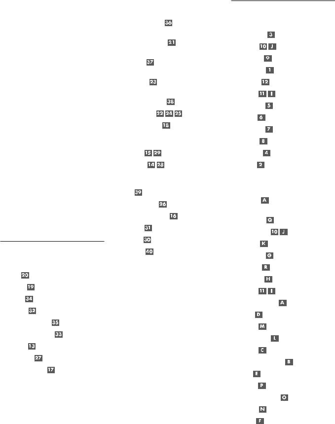
4:Outputs
Connexions de Sortie Salidas
AMPLIFIER |
SUBWOOFER |
FRONT |
SURROUND |
|
R |
CENTER |
|
L |
CENTER |
|
BACK |
||
|
RSP-1098
3 ZONE2
S-VIDEO
POWER
1 2
ON
COMPOSITE
OFF
SURROUND SOUND PROCESSOR
MODEL NO: RSP-1098
POWER CONSUMPTION: 70 WATTS
TV
RSP-1098
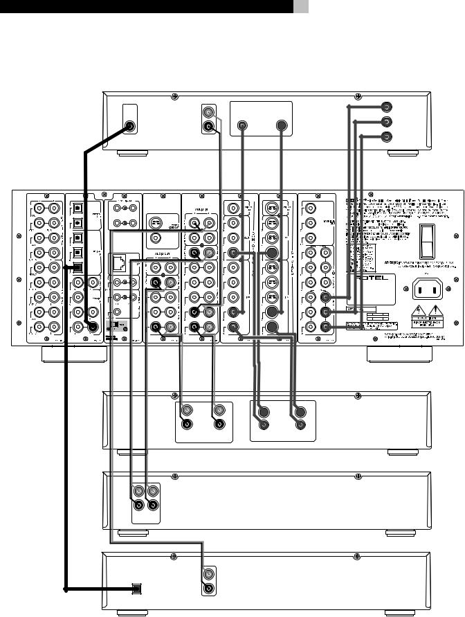
5:Source Connections Connexions d'Entrée Conexiones de las Fuentes
|
|
|
L |
|
|
|
|
R |
|
|
DIGITAL |
|
AUDIO |
|
|
OUTPUT |
|
OUTPUT |
|
3 |
ZONE2 |
|
|
|
|
|
S-VIDEO |
|
|
1 |
2 |
|
|
|
|
|
COMPOSITE |
|
|
|
|
|
L |
|
|
|
|
R |
|
|
|
REC |
AUDIO |
LINE |
|
|
IN |
OUT |
|
|
|
|
||
|
|
L |
|
|
|
|
R |
|
|
|
LINE |
REC |
|
|
|
OUT |
IN |
|
|
|
|
|
|
L |
|
|
|
|
R |
|
OPTICAL |
|
ANALOG |
|
|
DIGITAL OUTPUT |
OUTPUT |
||
|
|
10 |
|
|
|
|
DVD |
VIDEO |
|
Y |
|
OUTPUTS |
|
|
|
|
|
|
|
COMPOSITE |
S-VIDEO |
|
|
|
|
CR |
COMPONENT |
|
|
|
VIDEO |
|
|
CB |
|
|
|
|
RSP-1098 |
|
|
|
POWER |
|
|
|
ON |
|
|
|
OFF |
|
|
SURROUND SOUND PROCESSOR |
|
|
|
MODEL NO: RSP-1098 |
|
|
|
POWER CONSUMPTION: 70 WATTS |
|
|
|
|
VCR |
|
|
S-VIDEO |
|
|
|
COMPOSITE |
|
REC |
VIDEO |
LINE |
|
IN |
OUT |
|
|
|
|
||
|
|
|
TAPE |
|
|
|
CD |
11
6:Zone 2 Connections Connexions Zone 2 Conexiones de la Zona 2
CD
ROTEL RSP-1098
3 ZONE2
S-VIDEO
POWER
1 2
ON
COMPOSITE
OFF
SURROUND SOUND PROCESSOR
MODEL NO: RSP-1098
POWER CONSUMPTION: 70 WATTS
AMPLIFIER
ZONE 2 IR
RIGHT |
LEFT |
RSP-1098 Surround Sound Processor |
12 |
Contents
Boxed numbers refer to RSP-1098 illustration. Boxed letters refer to RR-1050 illustration.
Important Safety Instructions ................. |
3 |
1: Front and Rear Panels ................................... |
6 |
2: RR-1050 Remote ........................................... |
7 |
3: On-Screen Display/TFT Screen Menus ............. |
8 |
4: Outputs ......................................................... |
9 |
5: Source Connections ...................................... |
10 |
6: Zone 2 Connections ..................................... |
11 |
About Rotel ......................................... |
14 |
Getting Started .................................... |
14 |
Video features ................................................. |
14 |
Audio features ................................................. |
14 |
Surround features ............................................ |
14 |
Other features ................................................. |
14 |
Unpacking ....................................................... |
15 |
Placement ....................................................... |
15 |
CONNECTIONS |
15 |
Analog Audio Inputs & Outputs ............ |
15 |
CD Inputs .................................................. |
15 |
Tuner Inputs .............................................. |
15 |
TAPE Inputs ............................................... |
15 |
TAPE Outputs ............................................ |
15 |
VIDEO 1–5 Audio Inputs ........................... |
16 |
VIDEO 1–3 Audio Outputs ......................... |
16 |
MULTI Inputs ............................................. |
16 |
Preamp Outputs ........................................ |
16 |
ZONE 2 Audio Outputs ............................... |
16 |
Video Inputs & Outputs ........................ |
16 |
VIDEO 1–5 |
|
Composite Video Inputs ............................. |
17 |
VIDEO 1–3 |
|
Composite Video Outputs ........................... |
17 |
VIDEO 1–5 |
|
S-Video Inputs ........................................... |
17 |
VIDEO 1–3 |
|
S-Video Outputs ........................................ |
17 |
VIDEO 1–4 |
|
Component Video Inputs ........................... |
17 |
TV Monitor Outputs ...................... |
17 |
ZONE 2 Video Outputs ............................... |
17 |
Digital Audio Input & Outputs ............... |
17 |
Digital Inputs ..................................... |
18 |
Digital Outputs ................................... |
18 |
Other Connections ................................ |
18 |
AC Input ................................................... |
18 |
Master Power Switch ................................. |
18 |
12V TRIGGER Connections ......................... |
18 |
REM IN Jacks ............................................ |
18 |
IR OUT Jacks ............................................. |
18 |
Computer I/O ........................................... |
18 |
Making Connections .............................. |
19 |
CD Player ........................................................ |
19 |
DVD Player ...................................................... |
19 |
Cable, Satellite, or HDTV Tuner ......................... |
19 |
AM/FM Tuner .................................................. |
19 |
Audio Tape Recorder ........................................ |
19 |
VCR or Digital Video Recorder .......................... |
19 |
DVD-A or SACD Player ..................................... |
19 |
TV Monitor ....................................................... |
20 |
Amplifiers and Powered Subwoofers ................. |
20 |
OPERATING THE RSP-1098 |
20 |
Front Panel Overview .......................... |
20 |
Color TFT Display ...................................... |
20 |
MENU button ...................................... |
20 |
DISPLAY Button ......................................... |
20 |
STANDBY Button ....................................... |
20 |
VOLUME Knob ........................................... |
20 |
MUTE Button ...................................... |
21 |
FUNCTION Knob ........................................ |
21 |
PATH Button .............................................. |
21 |
SPEAKER Button ........................................ |
21 |
MODE Button ............................................ |
21 |
Remote Sensor .......................................... |
21 |
ZONE 2 LED .............................................. |
21 |
Remote Control Overview .................... |
21 |
Using the RR-1050 |
|
AUDIO Button ........................................... |
21 |
Programming the RR-1050 |
|
PRELOAD Button ....................................... |
21 |
MENU/OSD button ............................. |
21 |
ENTER Button ............................................ |
21 |
ON/OFF Buttons ....................................... |
21 |
POWER Button .......................................... |
21 |
VOLUME Button ......................................... |
22 |
MUTE Button ...................................... |
22 |
DEVICE/INPUT Buttons .............................. |
22 |
REC Button ................................................ |
22 |
ZONE Button ............................................. |
22 |
UP/DOWN Buttons .................................... |
22 |
+/– Buttons ............................................. |
22 |
Speaker Selection Buttons ......................... |
22 |
EQ Button ................................................. |
22 |
TONE Button ............................................. |
22 |
Surround Mode Buttons ............................. |
22 |
SUR+ Button ............................................. |
22 |
DYN Button ............................................... |
22 |
Basic Operations .................................. |
22 |
Power and Standby On/Off ......... |
22 |
Volume Adjustments ........................... |
23 |
Muting the Sound ............................... |
23 |
Display Options .................................. |
23 |
Selecting Inputs .................................... |
23 |
Selecting a Source Input |
|
from the Front Panel .......................... |
23 |
Selecting a Source |
|
from the Remote ......................... |
24 |
Overview of Surround Formats ............. |
24 |
Dolby Surround |
|
Dolby Pro Logic II ............................................ |
24 |
Dolby Digital ................................................... |
24 |
DTS 5.1 |
|
DTS 96/24 ...................................................... |
24 |
DTS Neo:6 ....................................................... |
25 |
6.1 and 7.1 Surround ...................................... |
25 |
DSP Music Modes ............................................. |
25 |
2Ch/5Ch/7Ch Stereo Formats .......................... |
25 |
Other Digital Formats ...................................... |
26 |
Automatic Surround Modes ................... |
26 |
Manually Selecting Surround Modes ...... |
26 |
Dolby Digital 5.1 |
|
Dolby Digital Surround EX ............................... |
27 |
Dolby Digital 2.0 ............................................. |
27 |
DTS 5.1 |
|
DTS 96/24 |
|
DTS-ES 6.1 ....................................................... |
27 |
MPEG Multichannel .......................................... |
28 |
Digital Stereo |
|
(PCM, MP3, and HDCD) ................................... |
28 |
Analog Stereo .................................................. |
28 |
13
Other Settings ...................................... |
29 |
|||||||||||||||||||||||||||
Temporary Speaker Level |
|
|
|
|
|
|
|
|
|
|
|
|
|
|
|
|
|
|
..... 29 |
|||||||||
|
|
|
|
|
|
|
|
|
|
|
|
|
|
|
||||||||||||||
Temporary Group Delay |
|
|
|
|
|
|
|
|
|
|
|
|
|
29 |
||||||||||||||
|
|
|
|
|
|
|
|
|
||||||||||||||||||||
Dynamic Range |
|
|
|
|
|
|
|
|
|
29 |
||||||||||||||||||
|
|
|
|
|
|
|
||||||||||||||||||||||
Contour/Tone Settings |
|
|
|
|
29 |
|||||||||||||||||||||||
|
|
|
||||||||||||||||||||||||||
Cinema EQ |
|
|
30 |
|||||||||||||||||||||||||
|
||||||||||||||||||||||||||||
Zone 2 Operation ................................. |
30 |
||||||||
Zone 2 Power On/Off Operation |
|
|
|
|
|
30 |
|||
|
|
|
|||||||
Controlling Zone 2 from the Front Panel .......... |
30 |
||||||||
Controlling Zone 2 |
|
||||||||
from the Remote Location |
|
|
|
|
|
........... |
30 |
||
SETUP |
31 |
||||||||
Menu Basics ......................................... |
31 |
||||||||
Navigation Buttons |
|
|
|
|
|
|
|
|
31 |
|
|
|
|
||||||
System Status .................................................. |
31 |
||||||||
Main Menu ...................................................... |
32 |
||||||||
Display Options ................................................ |
32 |
||||||||
Configuring Inputs ................................ |
32 |
||||||||
Input Setup ...................................................... |
32 |
||||||||
Multi Input Setup ............................................. |
33 |
||||||||
Dolby Pro Logic II ............................................ |
34 |
||||||||
DTS Neo:6 ....................................................... |
34 |
||||||||
Configuring Speakers and Audio ............ |
34 |
||||||||
Understanding Speaker Configuration .............. |
34 |
||||||||
Speaker Setup ................................................. |
35 |
||||||||
Advance Speaker Setup .................................... |
36 |
||||||||
Subwoofer Setup ............................................. |
36 |
||||||||
Test Tone ......................................................... |
37 |
||||||||
Delay Setup ..................................................... |
38 |
||||||||
Contour Setup .................................................. |
38 |
||||||||
|
English |
Miscellaneous Settings |
......................... 38 |
Other Options .................................................. |
38 |
Zone 2 Setup ................................................... |
39 |
Default Setup .................................................. |
39 |
MORE INFORMATION |
40 |
Troubleshooting .................................... |
40 |
Specifications ....................................... |
41 |
Audio .............................................................. |
41 |
Video ............................................................... |
41 |
General ........................................................... |
41 |
RSP-1098 Surround Sound Processor |
|
14 |
About Rotel |
Getting Started |
|
A family whose passionate interest in music led them to manufacture high fidelity components of uncompromising quality founded Rotel 40 years ago. Through the years that passion has remained undiminished and the family goal of providing exceptional value for audiophiles and music lovers regardless of their budget, is shared by all Rotel employees.
The engineers work as a close team, listening to, and fine tuning each new product until it reaches their exacting musical standards. They are free to choose components from around the world in order to make that product the best they can. You are likely to find capacitors from the United Kingdom and Germany, semi conductors from Japan or the United States, while toroidal power transformers are manufactured in Rotel’s own factory.
Rotel’s reputation for excellence has been earned through hundreds of good reviews and awards from the most respected reviewers in the industry, who listen to music every day. Their comments keep the company true to its goal - the pursuit of equipment that is musical, reliable and affordable.
All of us at Rotel, thank you for buying this product and hope it will bring you many years of enjoyment.
“DTS”, “DTS-ES Extended Surround”, “DTS ES® Matrix 6.1”, and “DTS ES® Discrete 6.1”, and “DTS Neo:6®”are trademarks of Digital Theater Systems, Inc.
Manufactured under license from Dolby Laboratories. “Dolby”, “Pro Logic”, “Surround EX”, and the double-D symbol are trademarks of Dolby Laboratories.
 , HDCD®, High Definition Compatible Digital ® and Pacific Microsonics™ are either registered trademarks or trademarks of Pacific Microsonics, Inc. in the United States and/or other countries. HDCD system manufactured under license from Pacific Microsonics, Inc. This product is covered by one or more of the following: In the USA: 5,479,168, 5,638,074, 5,640,161, 5,808,574, 5,838,274, 5,854,600, 5,864,311, 5,872,531, and in Australia: 669114. Other patents pending.
Thank you for purchasing the Rotel RSP-1098 Surround Sound Processor. The RSP-1098 is full-featured audio/video control center for analog and digital source components. It features digital processing for a wide range of formats including Dolby Surround®, Dolby Digital®, DTS® and HDCD® source material.
Video features
•Front panel widescreen color TFT screen for video or operating menus.
•Wideband 100 mHz video processing for HDTV signals.
•Full complement of composite, S-Video, and Component Video inputs and outputs
•Conversion of composite and S-Video signals to Component Video for output to TV monitor.
Audio features
•Rotel’s Balanced Design Concept combines advanced circuit board layout, comprehensive parts evaluation, and extensive listening tests for superior sound and reliability.
•Individual circuit boards grouped by function for maximum signal isolation.
•24-bit/128x oversampling analog-to-digital converters from AKM and Crystal Semiconductor 24-bit/192 kHz digital-to-analog converters
•Analog bypass mode for pure 2-speaker stereo with no digital processing.
•Optical and coax digital inputs and outputs.
•MULTI Input for 7.1 channel analog signals from DVD-A and SACD players. Subwoofer options include .1 channel pass through or bass redirect feature with an analog lowpass filter for a summed subwoofer output from seven channels.
•Automatic HDCD® decoding for signals from High Definition Compatible Digital® compact discs.
•Automatic decoding of digital signals from MP3 (MPEG-1 Audio Layer 3) players.
Surround features
•Automatic Dolby Digital® decoding for Dolby Digital® 2.0, Dolby Digital® 5.1, and Dolby Digital Surround EX® recordings.
•Dolby® Pro Logic II® decoding for Dolby Surround® matrix encoded recordings. Can be optimized for Music or Cinema sources plus an emulation mode for the original Dolby Pro Logic decoding.
•Automatic decoding for DTS® 5.1 channel, DTS-ES® Matrix 6.1 channel, DTS-ES® Discrete 6.1 channel, and DTS 96/24 digital recordings.
•DTS® Neo:6® Surround modes for deriving surround channels for 5.1, 6.1 or 7.1 channel systems from 2-channel stereo or matrix surround recordings. Can be optimized for Music or Cinema sources.
•Automatic decoding for MPEG Multichannel digital recordings.
•Rotel XS (eXtra Surround) automatically ensures proper decoding and optimum performance from any multichannel digital signal on 6.1 and 7.1 channel systems. Always active in any system with center back speaker(s), Rotel XS even works with signals that would not otherwise activate the proper decoding (such as non-flagged DTS-ES and Dolby Surround EX discs) or for which there is no extended surround decoder (such as DTS 5.1, Dolby Digital 5.1, and even Dolby Pro Logic II decoded Dolby Digital 2.0 recordings).
•Surround modes for playback of surround sound material on 2 channel and 3 channel systems for total compatibility.
•Four DSP Music modes.
Other features
•Multi-zone, multi-source capability with independent input selection and volume.
•User friendly ON-SCREEN DISPLAY (OSD) menu system with programmable labels for all inputs. Choice of languages.
•Learning remote control to operate the RSP-1098 and nine other components.
•Upgradeable microprocessor software to accommodate future upgrades.
•Four assignable 12V trigger outputs for remote turn-on of power amplifiers and other components.

Unpacking
Remove the unit carefully from its packing. Find the remote control and other accessories. Save the box as it will protect the RSP-1098 if you move or need to return it for maintenance.
Placement
Place the RSP-1098 on a solid, level surface away from sunlight, heat, moisture, or vibration. Make sure that the shelf can support the weight of the unit.
Place the RSP-1098 close to the other components in your system and, if possible, on its own shelf. This will make initial hookup, and subsequent system changes easier.
The RSP-1098 can generate heat during normal operation. Do not block ventilation openings. Allow a minimum of 10 cm (4 inches) of unobstructed space around the unit. If installed in a cabinet, make sure that there is adequate ventilation.
Don’t stack other components or objects on top of the RSP-1098. Don’t let any liquid fall into the unit.
15 |
English |
CONNECTIONS
Although, the RSP-1098’s rear panel looks daunting, connecting the unit to your system is straightforward. Each of the source components in the system are connected to the RSP-1098 inputs with a pair of standard RCA cables for analog audio, a video connection (composite, S-Video, or Component Video), and an optional digital audio cable (coax or optical).
NOTE: Surround formats like Dolby Digital and DTS are digital formats and the RSP-1098 can only decode them when a digital input signal is available. For this reason, you should always connect your DVD player’s digital outputs to the RSP-1098, using either the optical or coax inputs.
The outputs of RSP-1098 are sent to the power amplifier(s) with standard RCA cables from preamp audio outputs. The video signal from the RSP-1098 is sent to the TV monitor using composite video, S-Video, or Component Video connections.
In addition, the RSP-1098 has MULTI input connections for a source component that does its own surround decoding, remote IR sensor inputs, and 12V trigger connections for remote turn-on of other Rotel components.
NOTE: Do not plug any system component into an AC source until all connections have been properly made.
Video cables should have a 75 ohm impedance. The S/PDIF digital audio interface standard also specifies a 75 ohm impedance and all good digital cables adhere to this requirement. Do NOT substitute conventional audio interconnect cables for digital or video signals. Standard audio interconnects will pass these signals, but their limited bandwidth reduce performance.
When making signal connections, connect LEFT channels to LEFT channel jacks and RIGHT channels to RIGHT channel jacks. All RCA-type connections on the RSP-1098 follow these standard color codes:
Left channel audio: white RCA jack Right channel audio: red RCA jack Composite video: yellow RCA jack
NOTE: Each source input must be properly configured using the INPUT SETUP menu of the OSD menu system. We recommend going to this menu after connecting each source to configure it as desired. See Input Setup of the Setup section for information.
Analog Audio Inputs &
Outputs
The following connections are used for connecting analog audio signals to and from the RSP-1098. See the Making Connections topic for specific instructions on connecting each type of component.
NOTE: Normally, the RSP-1098 converts analog inputs to digital signals. All of the digital processing is available including bass management, digital crossovers, speaker level and delay settings and a number surround mode options including 2-ch stereo, Dolby Pro Logic II, etc. Alternatively, there is an analog bypass surround mode that routes 2-ch analog inputs directly to the Volume control and preamp outputs, bypassing the digital processing entirely for pure analog stereo.
CD Inputs 
A left/right pair of RCA analog audio inputs for connecting a CD player.
Tuner Inputs 
A left/right pair of RCA analog audio inputs for connecting an AM/FM tuner.
TAPE Inputs 
A pair of RCA inputs, labeled TAPE IN, for connecting the left/right analog audio signals from an audio tape deck or recording device.
TAPE Outputs 
A pair of RCA inputs, labeled TAPE OUT, for sending left/right line level analog audio signals for recording on a tape deck or recording device.
NOTE: These outputs should be connected to the inputs of the same tape deck connected to the TAPE IN inputs.

RSP-1098 Surround Sound Processor |
|
|
|
16 |
||
VIDEO 1–5 Audio Inputs |
|
|
Preamp Outputs |
|
|
|
|
|
|||||
Five pair of RCA inputs, labeled AUDIO IN (VIDEO IN 1 – 5), provide connections for left/ right analog audio signals from five additional source components. These inputs have corresponding video inputs and are used for VCRs, satellite TV tuners, DVD players, etc. However, they may also be used for additional audio only components, simply omitting the corresponding video connections.
VIDEO 1–3 Audio Outputs 
Three pair of RCA jacks, labeled AUDIO OUT (VIDEO OUT 1 – 3), provide connections for sending line level left/right line level analog audio signals for recording to a VCR.
These connections correspond to the VIDEO IN 1–3 connections. Make sure that you are consistent. If you hook up a particular VCR to the VIDEO 1 inputs, hook up the VIDEO 1 outputs to the same VCR.
NOTE: There are no analog audio outputs for VIDEO 4 & 5. Therefore, in an elaborate system, hook up all of the VCRs and recording devices to VIDEO 1–3 and use VIDEO 4 & 5 for playback only components.
NOTE: Video 1–3 can be used for audio-only tape decks, simply omitting the corresponding video connections.
MULTI Inputs 
A set of RCA inputs accept up to 7.1 channels of analog signals from a DVD-A or SACD player. There are inputs for FRONT L & R, CENTER, SUB, REAR L & R, and CENTER BACK 1 & 2.
These inputs bypass all digital processing in the RSP-1098 and are routed directly to the Volume control and preamp outputs
There are two subwoofer options for the MULTI input. Normally, the .1 channel input is passed through directly to the subwoofer output. An optional bass redirect feature duplicates the 7 main channels, sums them, and sends this mono signal through a 100 Hz analog low filter to the subwoofer output. This provides an unaltered analog bypass for the seven main channels along with a subwoofer signal derived from those channels.
A group of ten RCA analog audio outputs sends the RSP-1098’s line level output signals to external amplifiers and powered subwoofers. These outputs are variable level, adjusted by the RSP-1098 volume control. The eight connectors provide output for: FRONT L & R, CENTER 1 & 2, SURROUND L & R, CENTER BACK CB1 & CB2, and SUBWOOFER 1 & 2.
NOTE: Depending on your system configuration, you may use some or all of these connections. For example, if you only have one center channel, connect it to the CENTER 1 output. If you only have one center back channel, connect it to the CB1 output.
ZONE 2 Audio Outputs 
A pair of RCA inputs, labeled AUDIO OUT/ ZONE 2, sending analog audio signals to an external amplifier for a remote zone. These outputs can be configured as either fixed or variable level using the ZONE 2 SETUP menu.
NOTE: Only analog input signals are available at the Zone 2 outputs. Source components connected to only the digital inputs are not available in Zone 2.
To configure your system for Zone 2 operation, connect the left and right Zone 2 outputs on the RSP-1098 to the left and right channel inputs of the amplifier powering the remote speakers, using standard RCA audio cables.
Video Inputs & Outputs
These connections are used for connecting video signals to and from the RSP-1098. See the Making Connections section for specific instructions for each type of component.
The RSP-1098 provides Composite, S-Video, and Component Video connections. Composite video connections simplify system configuration; however, S-Video connections typically provide better picture quality. Component Video connections are required for HDTV or progressive scanned DVD video. Be aware of the following implications for the configuration of your system:
On Screen Display: The RSP-1098 OSD system is available on the TV monitor, regardless of what type of connection is made from the TV MONITOR outputs to the TV set. The OSD system is also available in the TFT screen.
NOTE: When using a progressive scan or 1080i video signal from the Component Video inputs, the TV monitor cannot display the video signal and the OSD menus at the same time. A “progressive” setting in the Display Options setup menu allows the use of the main OSD setup menus, even with progressive or HDTV signals. When the main OSD setup menus are activated, the progressive scan video input is interrupted and restored when the OSD menus are cancelled. The temporary OSD information displays (such as volume setting, etc.) are not displayed.All of the OSD displays are available on the front-panel TFT screen.
Output Conversion: The RSP-1098 converts composite and S-Video signals to Component Video signals for output to an NTSC or PAL standard TV monitor. For maximum convenience, connect the RSP-1098 to the TV monitor with Component Video connections. S-Video signals cannot be converted to composite outputs and vice versa.
NOTE: When a video input or inputs are selected for progressive mode on the DISPLAY OPTIONS menu, the conversion from composite or S-Video to Component Video output is not available for those inputs. The conversion from composite or S-VIDEO to Component Video output is only available for the other video inputs.
Many digital HDTV monitors adjust scan rates and other video parameters depending on the type of input connection. You may wish to make multiple connections between the RSP-1098 and the TV monitor, switching inputs on the TV to take advantage of these features.
TFT Display: If you choose to display video signals on the front panel display, keep in mind that it can only display signals from sources connected with composite video connections.
Even if you use Component Video connections, it is recommended that you also make composite video connections from each source component to the RSP-1098 so that the signal from each source component can be displayed on the front panel TFT display.

NOTE: The TFT display cannot properly display progressive scan (480p) signals. When a DVD player is outputting a progressive scan signal on Component Video outputs, its composite video outputs may not provide a usable signal. In this case, the TFT screen will not be able to display video from the DVD player or may display distorted video, even with a composite video connection.
VIDEO 1–5
Composite Video Inputs 
Five inputs accepts standard composite video signals from source components using standard 75 ohm RCA video cables.
VIDEO 1–3
Composite Video Outputs 
Three RCA jacks, labeled COMPOSITE VIDEO OUT 1–3, provide connections for sending composite video signals for recording on a VCR or other recording device.
These connections correspond to the VIDEO IN 1–3 connections. Make sure that you are consistent. If you hook up a particular VCR to the VIDEO 1 inputs, hook up the VIDEO 1 output to the same VCR.
NOTE: The RSP-1098 cannot convert S-Video or Component Video signals to composite video. Therefore, only signals received at the composite video inputs are available at these outputs.
VIDEO 1–5 S-Video Inputs 
Five inputs, labeled S-VIDEO IN 1–5 accept S-Video signals from source components.
VIDEO 1–3 S-Video Outputs 
Three S-VIDEO jacks, labeled S-VIDEO OUT 1–3, provide connections for sending S-Video signals for recording on a VCR or other recording device.
These connections correspond to the VIDEO IN 1–3 connections. Make sure that you are consistent. If you hook up a particular VCR to the VIDEO 1 inputs, hook up the VIDEO 1 output to the same VCR.
NOTE: The RSP-1098 cannot convert composite video or Component Video signals to S-Video. Only signals received at the S-Video inputs are available at these outputs.
17
VIDEO 1–4
Component Video Inputs 
Component Video connections split the video into three signals – luminance (Y) and separate chrominance (CB and CR) signals, allowing delivery of a reference-quality picture with high definition signals. Component Video connections should be used for progressive scan DVD players and high-definition digital television receivers. Each of these signals is carried by a separate 75 ohm video cable with RCA connectors.
NOTE: In progressive scan mode, a DVD player may not be able to output a usable video signal on its composite video outputs. In this case, the TFT screen will not be able to display video from the DVD player, even with a composite video input.
Four sets of inputs, labeled COMPONENT VIDEO IN 1–4 accept Component video signals from source components.
NOTE: When using a progressive scan or 1080i HDTV video signal from the Component Video inputs, the TV monitor cannot display the video signal and the OSD menus at the same time. A “progressive” setting in the Display Options setup menu allows the use of the main OSD setup menus, even with progressive or HDTV signals. When the main OSD setup menus are displayed, the progressive video signal is interrupted and restored when the OSD menus are cancelled. The temporary OSD information displays (such as volume setting, etc.) are not displayed.
TV Monitor Outputs 


The TV MONITOR outputs of the RSP-1098 send the video signal to your TV monitor. Three types of video output connections are provided
– RCA composite video, S-Video, and Component Video.
The composite video output only sends signals from composite video inputs to the TV monitor. The S-Video output only sends signals from S-Video video inputs to the TV. The Component Video output converts signals from ANY type of source input to the TV. If you have connected all of your source components with the same type of connection, then you only need to make one connection from the RSP-1098 to the TV monitor. If you connect the RSP-1098 to the TV monitor with Component Video connections, you also only need
English
to make one type of connection because composite and S-Video signals are converted to Component Video.
NOTE: When a video input or inputs are selected for progressive mode on the DISPLAY OPTIONS menu, the conversion from composite or S-Video to Component Video output is not available for those inputs. The conversion from composite or S-VIDEO to Component Video output is only available for the other video inputs.
ZONE 2 Video Outputs 
The ZONE 2 Video outputs of the RSP-1098 send the video signal to a TV monitor in the remote zone. Two types of video output connections are provided – RCA composite video and S-Video.
NOTE: Only composite video input signals are available at the Zone 2 composite video outputs. Only S-Video input signals are available at the Zone 2 S-Video video outputs.
Digital Audio
Input & Outputs
The RSP-1098 provides digital connections which may be used in place of, or in addition to, the analog audio input and output connections described in the previous sections. These connections include eight digital inputs and four digital outputs for recording.
These digital connections can be used with any source component that supplies a digital signal, such as a DVD player, CD player, or satellite TV tuner.
NOTE: With a digital connection, the RSP-1098 will be used to decode the signal, rather than the source component’s internal decoders. In general, you must use digital connections for a DVD player or other component that supplies a Dolby Digital or DTS signal; otherwise the RSP-1098 will not be able to decode these formats.

RSP-1098 Surround Sound Processor |
|
|
|
18 |
||||
Digital Inputs |
|
|
|
|
Master Power Switch |
|
|
|
|
|
|
||||||
The RSP-1098 accepts digital inputs from source components such as CD players, satellite TV tuners, and DVD players. The built-in digital processor senses and adjusts to the correct sampling rates.
There are eight digital inputs on the rear panel, five coaxial and three optical. These digital inputs can be assigned to any of the input sources using the INPUT SETUP screen during the setup process. For example, you can assign the COAXIAL 1 digital input connector to the VIDEO 1 source and the OPTICAL 2 digital input to the VIDEO 3 source.
NOTE: When using digital connections, you should also make the analog audio input connections described previously. The analog connection is necessary to record to an analog recorder in some circumstances or for ZONE 2 operation
Digital Outputs 

The RSP-1098 has four digital outputs (two coaxial and two optical) to send the digital signal from any of the digital inputs to a digital recorder or outboard digital processor. When a digital input source signal is selected for listening, that signal is automatically sent to both digital outputs for recording.
NOTE: Only digital signals from source components are available at these outputs. Analog signals cannot be converted and are not available at the digital outputs.
The large rocker switch on the rear panel is a master power switch. When it is in the OFF position, power to the unit is completely off. When it is in the ON position, the front panel STANDBY and remote control ON/OFF buttons can be used to active the unit or put it standby mode.
NOTE: After all connections are completed, the rear panel master power switch should be put in the ON position and usually left in that position.
12V TRIGGER Connections 
Many Rotel amplifiers offer the option of turning them on and off using a 12 volt trigger. These four connections provide this 12 volt trigger signal from the RSP-1098. When the RSP-1098 is activated, a 12 volt DC signal is sent to the amplifiers to turn them on. When the RSP-1098 is put in STANDBY mode, the trigger signal is interrupted and the amplifiers turn off.
To use the remote turn on feature, connect one of the RSP-1098’s 12V TRIG OUT jacks to the 12 volt trigger input of a Rotel amplifier, using a cable with mono 3.5 mm mini-plugs on both ends. The +12 V DC signal appears at the “tip” connector.
NOTE: The 12V Trigger outputs can be configured to turn on only when specific input sources are activated. See the Input Setup and Zone 2 Setup menus in the Setup section of this manual for details.
features of the RSP-1098 and can be relayed to other components. Remote control signals sent to the ZONE 3 REM IN can be used to select the RECORDING source (the signal available at the TAPE OUT connections).
Consult your authorized Rotel dealer for information on external receivers and the proper wiring of a 3.5 mm mini-plugs to fit the REM IN jacks.
NOTE: The IR signals from the EXT REMOTE IN jack (as well as those from the ZONE 2/ ZONE 3 REMOTE IN jacks) can be relayed to source components using external IR emitters or hard-wired connections from the IR OUT jacks. See the following section for additional information.
IR OUT Jacks 
The IR OUT 1 & 2 jacks send IR signals received at the ZONE REM IN jacks or the EXT REM IN jack to an infrared blaster or emitter placed in front of a source component’s IR sensor. In addition, the IR OUT can be hardwired to Rotel CD players, DVD players, or tuners with a compatible connector.
These outputs are used to allow IR signals from Zone 2 to be sent to the source components, or to pass along IR signals from a remote in the main room when the sensors on the source components are blocked by installation in a cabinet.
See your authorized Rotel dealer for information on IR emitters and repeater systems.
Other Connections
AC Input 
Your RSP-1098 is configured at the factory for the proper AC line voltage in the country where you purchased it (USA: 115 volts/60Hz AC or CE: 230 volts /50 Hz AC ). The AC line configuration is noted on a decal on the back of your unit.
Plug the supplied cord into the AC INPUT receptacle on the back of the unit.
NOTE: Memorized settings and video labels are preserved indefinitely, even if the RSP-1098 is disconnected from AC power.
REM IN Jacks 
Three 3.5 mm mini-jacks (labeled REM IN, ZONE 2, and ZONE 3) receive command codes from an industry-standard infrared receivers (Xantech, etc.), used when the IR signals from a hand held remote control cannot reach the front panel IR sensor.
EXT: The EXT jack is used with an outboard IR receiver to duplicate the front panel IR sensor. This feature is useful when the unit is installed in a cabinet and the front panel sensor is blocked or when IR signals need to be relayed to other components.
ZONE 2 and ZONE 3: These two jacks are used with IR repeater systems to receiver signals from IR control systems in remote locations. For example, remote control signals sent to the ZONE 2 REM IN control the ZONE 2
Computer I/O 
The RSP-1098 can be operated from a computer with audio system control software from third-party developers. This control is accomplished by sending operating codes from the computer via a hard-wired RS-232 serial connection. In addition, the RSP-1098 can be updated using special software from Rotel.
The COMPUTER I/O input provides the necessary network connections on the rear panel. It accepts standard RJ-45 8-pin modular plugs, such as those commonly used in 10-BaseT UTP Ethernet cabling.
For additional information on the connections, cabling, software, and operating codes for computer control or updating of the RSP-1098, contact your authorized Rotel dealer.

Making Connections
CD Player
Connect the left and right analog outputs from the CD player to the AUDIO IN jacks labeled CD (left and right).
Optional: Connect the digital output of the CD player to any of the Optical or Coax digital inputs on the RSP-1098. Use the INPUT SETUP screen to assign that digital input to the CD source.
There are no video connections for a CD Player.
DVD Player
DVD connections can be made to the VIDEO 1, 2, 3, 4, or 5 inputs. In elaborate systems, you may wish to use VIDEO 4 or VIDEO 5 for DVD players, since these inputs do not have corresponding OUTPUT connections. If you choose VIDEO 1, make sure that you use VIDEO 1 inputs and outputs for all analog audio and video connections.
Connect a video cable (Composite Video, S-Video, and/or Component Video from the output of the DVD player to the appropriate VIDEO IN 1–5 input. If you intend to use the progressive scan feature with an HDTV monitor, you should use Component Video connections. If you choose S-Video or Component Video connections, you should also make a standard Composite Video connection so that the DVD menus can be displayed on the RSP-1098 front panel display.
Connect the digital output of the DVD player to any one of the OPTICAL IN or COAXIAL IN digital inputs on the RSP-1098. Use the INPUT SETUP screen to assign that digital input to the same video input source used above. For example, if you use the Video 4 inputs above, assign the digital input to the VIDEO 4 input.
If you want to record the audio signal from the DVD player, connect the left and right analog outputs from the DVD player to the left and right AUDIO IN jacks corresponding to the VIDEO IN input selected above.
Cable, Satellite, or HDTV Tuner
TV tuner connections can be made to the VIDEO 1, 2, 3, 4, or 5 inputs. In elaborate systems, you may wish to use VIDEO 4 or VIDEO 5 for TV tuners, since these inputs do not have
19
corresponding OUTPUT connections. If you choose VIDEO 1, make sure that you use VIDEO 1 inputs and outputs for all analog audio and video connections.
Connect a video cable (Composite Video, S-Video, and/or Component Video) from the output of the TV tuner to the appropriate VIDEO IN 1–5 input. For HDTV signals, you should use Component Video connections. If you choose S-Video or Component Video connections, you should also make a standard Composite Video connection so that the TV signals can be displayed on the RSP-1098 front panel display.
Connect the left and right analog outputs from the TV tuner to the left and right AUDIO IN jacks corresponding to the VIDEO IN input selected above.
Optional: Connect the digital output of the TV tuner to any one of the OPTICAL IN or COAXIAL IN digital inputs on the RSP-1098. Use the INPUT SETUP screen to assign that digital input to the same video input source used above. For example, if you use the Video 4 inputs above, assign the digital input to the VIDEO 4 input.
AM/FM Tuner
Connect the left and right analog outputs from the tuner to the AUDIO IN jacks labeled TUNER (left and right).
There are no digital connections or video connections for an AM/FM tuner.
Audio Tape Recorder
Connect the left and right analog outputs from an audio tape deck to the AUDIO IN jacks labeled TAPE IN (left and right).
Connect the left/right AUDIO OUT/TAPE OUT jacks to the inputs on the audio tape deck.
Optional: For a digital recording device, connect the digital output of the recorder to one of the OPTICAL IN or COAXIAL IN digital inputs on the RSP-1098. Use the INPUT SETUP screen to assign that digital input to the TAPE source. If the recording device accepts a digital recording input, connect one of the OPTICAL OUT or COAXIAL OUT connections to the digital input of the recorder.
No video connections are required for an audio recording device.
English
VCR or Digital Video Recorder
VCR connections can be made to the VIDEO 1, VIDEO 2, or VIDEO 3 inputs and outputs. If you choose VIDEO 1, make sure that you use VIDEO 1 inputs and outputs for all analog audio and video connections.
Connect video cables (Composite Video, S-Video, and/or Component Video) from the output of the VCR to the appropriate VIDEO IN 1–3 input. If you choose S-Video or Component Video connections, you should also make a standard Composite Video connection so that the TV signals can be displayed on the RSP-1098 front panel display.
Connect a video cables (Composite Video, S-Video, and/or Component Video) from the VIDEO OUT jacks to the VCR inputs.
Connect the left and right analog outputs from VCR to one pair of the AUDIO IN jacks labeled VIDEO 1–3.
Connect the left and right AUDIO OUT jacks for VIDEO 1–3 to the analog inputs on the VCR.
Optional: For a digital recording device, connect the digital output of the recorder to one of the OPTICAL IN or COAXIAL IN digital inputs on the RSP-1098. Use the INPUT SETUP screen to assign that digital input to the VIDEO source (VIDEO 1, 2, or 3) used for the previous connections. If the recording device accepts a digital recording input, connect one of the OPTICAL OUT or COAXIAL OUT connections to the digital input of the recorder.
DVD-A or SACD Player
To hook up a DVD-A, an SACD player (or any external surround decoder), use audio RCA cables to connect the outputs of the player to the RCA jacks labeled MULTI INPUT, making sure that you observe proper channel consistency, i.e. connect the right front channel to the R FRONT input, etc. Depending on your system configuration, make six connections (FRONT L & R, SURROUND L & R, CENTER, and SUBWOOFER), seven connections (adding a CENTER BACK connection), or eight connections (adding two CENTER BACK connections).
The MULTI inputs are analog bypass inputs, passing signals directly through to the Volume Control and preamp outputs, bypassing all of the digital processing. The RSP-1098 provides an optional bass redirect feature that duplicates the seven main channels and passes them

RSP-1098 Surround Sound Processor |
20 |
through an analog 100 Hz low pass filter, creating a summed mono subwoofer output derived from the main channels. See the INPUT SETUP menu in the Setup section of this manual for details on bass redirect feature.
TV Monitor
Connect the TV MONITOR output to the corresponding input on your television monitor, using composite video, S-Video, and/or Component Video cables.
NOTE: The RCA composite video output only sends signals from RCA composite video source inputs to the TV monitor. The S-Video output only sends signals from S-Video video source inputs to the TV. The RSP-1098 upconverts composite and S-Video signals to Component Video signals. Therefore, the Component Video output sends signals from any source input to the TV.
When configuring the unit, you must specify either an NTSC or a PAL standard TV monitor. See the Other Options menu in the Setup section of this manual.
Amplifiers and Powered
Subwoofers
To hook up a powered subwoofer, connect a standard RCA audio cable from either the two PREOUT jacks labeled SUB to the input on the subwoofer’s power amp. Both SUB outputs provide the same signal.
To hook up amplifiers, connect an audio cable from each PREOUT jack to the input of the amplifier channel that will power the corresponding speaker. In a full home theater system, you will need to make five different connections in addition to the subwoofer . These connections are labeled FRONT L &R, CENTER, and REAR L & R. There are two CENTER jacks, use either jack for a single center channel or both if you have two center channels
In six or seven channel systems, you will make one or two additional connections for center back speaker(s). These jacks are labeled CB1 and CB2. Use CB1 for a single center back channel.
Make sure that you have each output connected to the correct amplifier channel (front right, left rear, etc.).
OPERATING
THE RSP-1098
Considering its large number of features, settings, and options, the RSP-1098 is remarkably easy to operate. The key to the operating the RSP-1098 is its system of On-Screen Displays (OSD) which guide you through various choices. These OSD menus can appear on the television monitor and/or on the front panel TFT color LCD screen.
The RSP-1098 can be operated from the front panel or the remote control. Front panel controls are unusually simple to use, with just a few knobs and buttons to guide you through OSD menu options. The remote control provides more complete control options.
To guide you through the operation of the RSP-1098, this section of the manual starts with explaining the basic layout and function of the front panel and the remote control. Then, we explain the basic operations such as turning the unit on and off, adjusting volume, selecting a source for listening, etc. Following that is a detailed explanation of surround sound modes and how to configure the RSP-1098 for various types of recordings. Finally, there are instructions for additional features and Zone 2 operations. All of these are features that may be used in normal use. The last section of the manual (Configuration) details options that may be selected during initial setup and configuration of the unit, many of which will be set once and left untouched.
Throughout this manual, numbers in gray boxes refer to the RSP-1098 illustration at the front of this manual. Letters refer to the RR-1050 remote illustration. When both appear, the function is found on both the RSP-1098 and the remote. When only one appears, that function is found only on the RSP-1098 or the remote.
Front Panel Overview
The following is a brief overview of the control and features on the front panel of the RSP-1098. Details concerning the use of these controls are provided in subsequent sections of this manual describing various tasks.
Color TFT Display 
In the center of the front panel is a large widescreen format TFT color LCD display. The display is used for two purposes: displaying OSD menus and as a built-in TV monitor for any composite video signal coming into the RSP-1098, making it ideal for navigating DVD menus, monitoring a remote camera, or just watching TV.
MENU button 

The MENU button toggles on or off the SYSTEM STATUS menu showing the current settings of the RSP-1098. Pressing the ENTER button on the remote (or the FUNCTION knob on the front panel) from the SYSTEM STATUS menu takes you to additional menus for configuring the RSP-1098’s many options. See the Setup section of the manual for more detail on the OSD menus.
NOTE: Turn off power to the front panel display by pressing and holding the MENU button.
DISPLAY Button 
The DISPLAY button provides access to two settings for the front panel TFT screen and OSD menu displays: selecting a video source for display on the TFT screen and selecting whether OSD menus are displayed on the front panel TFT, the TV monitor, or both.
STANDBY Button 
The front panel STANDBY button activates or deactivates the unit. The rear panel master STANDBY button must be in the ON position for the remote standby function to operate.
VOLUME Knob 
The large knob at the right side of the front panel is the master VOLUME control, adjusting the output level of all channels simultaneously. In addition, it can be used to adjust the ZONE 2 volume.
MUTE Button 

Push the MUTE button once to turn the sound off. An indication appears in the front panel and on-screen displays. Press the button again to restore previous volume levels.
NOTE: Rotating the volume knob also cancels the muting function.
FUNCTION Knob 
The large knob at the left side of the front panel is dual action control for navigating OSD menus. Rotate the control to the left or right to change settings on the menus. Push the knob to enter the new setting.
PATH Button 
The RSP-1098 can independently select sources for listening, recording, and use in a remote Zone 2 location. The PATH button toggles among listening, recording, and Zone 2 selection modes. In listening mode, input selection and volume adjustments change the main listening room. In Zone 2 mode, these adjustments change the remote zone. In recording (or Zone 3) mode, a source is selected for output to VCRs or other recorders.
SPEAKER Button 
During the setup of the RSP-1098, precise volume levels adjustments for each speaker are memorized for the proper playback of Dolby Digital and other surround sound formats. These default settings will be used each time you turn on the RSP-1098. The SPEAKER button on the front panel selects a speaker for temporary adjustments that remain in effect only until you change to a different input source or turn the RSP-1098 off. The actual adjustment is made with the FUNCTION knob.
The SPEAKER button can also be used to make a temporary adjustment to the group delay or “lip-synch” delay. Like the speaker settings, this is a temporary adjustment that overrides the permanent default setting for a video source until a different input source is selected or the unit is turned off.
21
MODE Button 
Although surround mode selection is generally automatic, the MODE button on the front panel can be used (with the FUNCTION knob) to temporarily override the default surround mode for a particular input. The available options depend on the type of source input (digital or analog) and the type of recording (Dolby Digital, DTS, PCM stereo, etc.)
Remote Sensor 
This sensor receives IR signals from the remote control. Do not block this sensor.
ZONE 2 LED 
A small LED in the upper left portion of the front panel lights when the remote ZONE 2 feature of the RSP-1098 is in use.
Remote Control Overview
The RSP-1098 includes a full-function learning remote control that can operate the RSP-1098 plus nine other audio/video components.
A separate manual gives detailed instructions on programming and using the RR-1050 to replace all of the remote controls in your system. The RR-1050 manual covers many extra features (such as custom labeling of remote buttons that appear in its LCD display). To avoid duplication, we provide only basic information about using the RR-1050 to operate the RSP-1098 in this manual.
Many of the RR-1050 functions duplicate the front panel controls. For that reason, we cover the controls on the remote under appropriate topics throughout this manual. Letters in gray boxes next to the name of a function refers to the labeled illustration of the remote at the front of this manual.
Using the RR-1050
AUDIO Button 
To operate the RSP-1098 with the remote, make sure that the AUDIO mode is active by pressing the AUD button on the remote before you start. If one of the other buttons (CD, TAPE, etc.) is pressed, the remote will control another component, not the RSP-1098. The AUDIO mode will stay active until another DEVICE/ INPUT button is pressed.
English
Programming the RR-1050
PRELOAD Button 
The RR-1050 is programmed at the factory to operate the RSP-1098. Should the AUDIO command set on your RR-1050 not operate the RSP-1098, the programming may have been inadvertently changed. To restore the RSP-1098 programming, press the recessed PRELOAD button on the remote with the tip of a ballpoint pen.
NOTE: Pushing the PRELOAD button will erase all custom programming and learned commands, restoring the RR-1050 to its factory condition.
MENU/OSD button 

Push this button on the remote to turn on the OSD menu system. If the menu system is already visible, push this button to cancel the display.
The front panel TFT display can be turned off by pressing and holding the MENU/OSD button on the remote for three seconds. Briefly press the MENU/OSD button again to turn the display back on. The display also turns back on whenever the STANDBY button on the front panel or remote is pressed.
ENTER Button 
The ENTER button is used to confirm and memorize various settings in the setup and operation of the RSP-1098. Its use is described in detail in the relevant sections.
ON/OFF Buttons 
The power ON and OFF buttons on the remote provide discrete ON and OFF commands to activate the unit or put it in standby mode. The rear panel master POWER switch must be in the ON position for the remote standby function to operate.
POWER Button 
The POWER button on the remote provides the same basic function as the ON/OFF buttons, except in a conventional toggle format. Press the button once to activate the unit; press again to put the unit into standby mode.
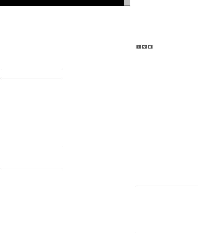
RSP-1098 Surround Sound Processor
VOLUME Button 
The large rocker button is the master VOLUME control, adjusting the output level of all channels simultaneously.
22
+/– Buttons |
|
|
Basic Operations |
This pair of buttons is used to change settings |
|
||
on a selected line in the OSD menus. Also used |
This section covers the basic operating con- |
||
for selecting options in some surround modes. |
trols of the RSP-1098 and the remote. |
||
MUTE Button 

Push the MUTE button once to turn the sound off. An indication appears in the front panel and on-screen displays. Press the button again to restore previous volume levels.
NOTE: Pressing the volume buttons on the remote also cancels the muting function.
DEVICE/INPUT Buttons 
The ten buttons at the top of the remote have two functions:
Short press: A short press of any button changes the device that the remote operates, but does not change the RSP-1098’s input selection.
Long press: A longer press changes the remote control device and changes the RSP-1098 source input for listening/viewing in the main room.
NOTE: A long press of the EXT button changes the input to the 7.1 channel analog MULTI INPUT. Pressing the AUD button only changes the remote device; there is no input source associated with this button.
REC Button 
Press this button before a long press of any DEVICE/INPUT button to select a source for recording. The signal from the selected source appears at the TAPE OUT connectors.
ZONE Button 
Press this button before a long press of any DEVICE/INPUT button to select a source for ZONE 2.
UP/DOWN Buttons 
This pair of buttons is used to move the cursor up or down to select lines in the OSD menus. These buttons are also used in conjunction with the TONE button to make CONTOUR/TONE adjustments.
Speaker Selection Buttons 
These three buttons are used to select a speaker or group of speakers for temporary level adjustments.
EQ Button 
This button is used to turn on and off the Cinema EQ feature, a high-cut filter useful for older movie soundtracks.
TONE Button 
This button is used in setting the Contour adjustments. It toggles between high frequency (HF) and low frequency (LF) modes. Once a mode is selected, the UP/DOWN buttons are used to make the adjustments.
Surround Mode Buttons 
Five buttons on the remote (2CH, PLC, PLM, 5CH, 7CH) allow direct selection of certain surround modes: 2-channel stereo, Pro Logic II Cinema, Pro Logic II Music, 5-channel stereo, or 7-channel stereo. The function of these buttons varies depending on the type of recording being played. See the Manually Selecting Surround Modes section for detailed information.
SUR+ Button 
This button is used in conjunction with the +/– buttons for manual selection of surround modes and features. See the Manually Selecting Surround Modes section for information.
DYN Button 
Used for selecting the dynamic range control setting in Dolby Digital surround mode.
Power and Standby On/Off
The rear panel POWER switch on the RSP-1098 is a master power switch. The button must be pressed IN for the unit to operate. When it is in the OUT position, the unit is fully off and cannot be activated from the front panel or remote control.
The STANDBY button on the front panel, the discrete ON/OFF buttons on the remote, and the POWER button on the remote function as a standby switches, activating or deactivating the unit. In standby mode, minimal power is supplied to the microprocessor. When the unit has AC power applied and the rear panel POWER switch is on, the front panel STANDBY LED lights, regardless of whether the unit is in standby mode or activated in the main room.
In normal operation, the rear panel POWER switch is always left in the ON position and the RSP-1098 is activated and deactivated using the front panel STANDBY button or the remote ON/OFF buttons or the remote POWER button. The ON/OFF buttons and the POWER button on the remote provide essentially the same function with the ON/OFF buttons providing discrete ON and OFF commands while the POWER button provides a standard toggle on/off function.
When using the Zone 2 capability of the RSP-1098, the standby activation is completely independent for the main room and Zone 2. ON/OFF commands sent from the remote in the main room will not effect Zone 2. Pressing the ON/OFF buttons on a remote located in Zone 2 will only effect that zone and not the main room. When the unit is activated in ZONE 2, the ZONE 2 LED on the front panel is lit.
There are three available power mode options, which may be useful in configuring the RSP-1098 for special system configurations. See the Other Options menu in the Setup section of this manual for additional details on changing the default standby behavior.

Volume Adjustments 

The listening volume of the RSP-1098 can be adjust from the front panel or the remote.
Front Panel: Rotate the front panel VOLUME knob clockwise to increase the volume, counterclockwise to decrease.
Remote: Press the VOL UP button to increase the volume; press the VOL DOWN button to decrease.
When you adjust the volume, the setting is shown on the TV monitor and/or the front panel TFT display. The current volume setting is also shown on the SYSTEM STATUS OSD screen.
NOTE: The front panel VOLUME control can be used to change the volume in Zone 2. Press the front panel PATH button three times to change from the LISTENING to the ZONE 2 control mode as shown by the OSD and/ or TFT display. Turning the VOLUME knob will then adjust the volume setting for ZONE 2. After 5 seconds, the PATH setting and VOLUME control revert to normal LISTENING mode operation.
23
Display Options 

The front panel DISPLAY button provides access to two settings of the front panel TFT screen and OSD menu displays: selecting a video source for display on the TFT screen and selecting whether OSD menus are displayed on the front panel TFT screen, the TV monitor, or both.
•To view a video source on the TFT screen: press the DISPLAY button once. Then, rotate the FUNCTION knob to select a source. Available display options are VIDEO 1–5, SOURCE (the same source selected for listening), or no video display.
•To change the OSD setting: press the DISPLAY button two times. Then, rotate the FUNCTION knob to select an OSD option. Available options are to view OSD menus on the TFT/LCD screen, the TV monitor, or both.
•To shut off power to the TFT screen: press and hold the MENU/OSD button on the remote or the MENU button on the front panel for 3 seconds.
Muting the Sound 

The volume of the RSP-1098 can be turned off or muted. Push the MUTE button on the front panel or the remote once to turn the sound off. A MUTE indication appears in the OSD and/or TFT displays. Press the MUTE button again to restore previous volume levels.
NOTE: If the TFT screen and TV monitor are turned off, muting the sound gives no visual indication, creating a false impression that the RSP-1098 is not working correctly.
Selecting Inputs
Up to three audio sources and five audio/video sources (Tuner, CD, DVD, VCR, etc.) can be connected to the RSP-1098. Any of these sources can be independently selected for listening/viewing in the main room, for recording, or for listening/viewing in a remote Zone 2 location.
The OSD and/or TFT displays show the name of the current source selection as it is made. The labels for all input sources can be customized to match your components.
All of the source inputs can be customized using the OSD configuration menus to accept either analog signals or digital signals from one of the eight assignable digital inputs. When a digital input is assigned, the RSP-1098 checks for the presence of a digital signal at that input. If a digital signal is present when the source is selected, it is automatically activated and the proper surround mode enabled. If no digital signal is present, the analog inputs for that source are selected. This auto-sensing is the preferred configuration for digital source inputs such as DVD players. When an ANALOG
English
input is assigned, the unit will not access a digital signal, even though one may be available at the digital input.
By default, the source DEVICE/INPUT buttons are factory configured to select the following inputs:
CD: |
Analog input |
Tuner: |
Analog input |
Tape: |
Analog input |
Video 1: |
Digital Coaxial 1 |
Video 2: |
Digital Coaxial 2 |
Video 3: |
Digital Coaxial 3 |
Video 4: |
Digital Optical 1 |
Video 5: |
Digital Optical 2 |
Each source input should be configured using the INPUT SETUP menu system to use the desired input type (analog or digital auto-sens- ing).
NOTE: In addition to selecting analog or digital signals, the configuration options also permit custom labeling and selection of a default surround mode for each of the eight inputs.
Selecting a Source Input from the Front Panel 

Selecting a source input from the front panel is a two-step process. First choose whether you are changing the source for LISTENING in the main room, for RECORDING, or for ZONE 2. Then, select the desired source.
To select a source for LISTENING:
1.Press the PATH button one time for LISTENING selection.
2.Rotate the FUNCTION knob to cycle through the list of sources until you reach the desired source.
To select a source for RECORDING:
1.Press the PATH button two times for RECORDING selection.
2.Rotate the FUNCTION knob to cycle through the list of sources until you reach the desired source.
Selecting the “SOURCE” option links the listening source to the record outputs, recording whatever listening source is selected now or in the future for recording.
NOTE: See the section on Zone 2 operations for details of selecting a source for the remote zone.

RSP-1098 Surround Sound Processor |
24 |
Selecting a Source from the Remote 


To select a source for LISTENING in the main room: press and hold one of the DEVICE/INPUT buttons for more than one second. To select the MULTI INPUT, press the EXT button.
NOTE: A short press of a DEVICE/INPUT button changes the remote control device only, but does not change the source input.
To select a source for RECORDING: Press the REC button and then press one of the DEVICE/INPUT buttons within 5 seconds.
Alternatively, you can press the REC button and then use the +/– buttons to scroll through the available source options. Select any input (CD, TUNER, TAPE, or VIDEO 1–5). Selecting the SOURCE option links the recording source to the input selected for main room listening. Whatever input is selected for listening is also sent to the record outputs.
To select a source for Zone 2: Press the ZONE button and then press one of the DEVICE/INPUT buttons within 5 seconds.
Alternatively, you can press the ZONE button and then use the +/– buttons to scroll through the available source options. Select any input (CD, TUNER, TAPE, or VIDEO 1–5). Selecting the SOURCE option links the Zone 2 source to the input selected for main room listening. Whatever input is selected for the main room is also sent to the Zone 2 outputs.
Overview of
Surround Formats
To get the best performance from your RSP-1098, it helps to understand the many surround sound formats available today, to know which decoding process to use for a particular recording, and how to select it. This section provides basic background information about surround sound formats. The following sections provide detailed operating instructions for automatic and manual selection of surround modes.
Dolby Surround
Dolby Pro Logic II
The most widely available surround sound format for consumer audio/video is Dolby Surround®, available on nearly all commercial VHS tapes, many television broadcasts, and most DVDs. Dolby Surround is the consumer version of the analog Dolby Stereo system first introduced in the film industry in 1972. It is a matrix-encoding system that records front left, front center, front right, and a mono surround channel into a 2-channel stereo recording. During playback, a Dolby Pro Logic® or Pro Logic II decoder extracts each channel and distributes it to the appropriate speakers.
The original Dolby Pro Logic decoder delivered a mono signal with reduced high-fre- quency content to the surround speakers. A more advanced decoder in the RSP-1098, Dolby Pro Logic II, increases the separation and frequency response of the surround channels for significantly improved performance with Dolby Surround encoded recordings.
Dolby Pro Logic II decoding should be used for any analog recording labeled “Dolby Surround” or any Dolby Digital 2.0 soundtrack. Dolby Pro Logic II does a superb job deriving surround sound from conventional 2-channel stereo recordings, using phase relationships to extract front, right, center, and surround channels. A “music mode” makes Pro Logic II an excellent choice for audio CDs.
Dolby Digital
In 1992, an digital recording system, called Dolby Digital, was first used in the film industry. Dolby Digital is a recording/playback system that uses compression techniques to store large amounts of audio data efficiently, much like the JPEG format stores large photographs in small files on a computer. Because it is capable of performance beyond that of audio CDs and can tailor its output for a wide ranges of system configurations, Dolby Digital is the standard audio format for DVDs and for digital television broadcasting in the United States.
The Dolby Digital system can be used to record up to six discrete audio channels, but can also be used for fewer. For example, a Dolby Digital 2.0 soundtrack is a digital 2-channel recording of a matrix encoded Dolby Surround soundtrack.. To play a Dolby Digital 2.0 recording, use Dolby Pro Logic II decoding as previously described.
The most common use of Dolby Digital in newer films, in both the film industry and in home theater, is Dolby Digital 5.1. Instead of encoding multiple surround channels on a two-channel recording, Dolby Digital 5.1 records six discrete channels: front left, front center, front right, surround left, surround right, and a Low Frequency Effects (LFE) channel containing ultralow bass signals intended for a subwoofer. A Dolby Digital decoder extracts the channels from the digital bitstream, converts them to analog signals and routes them to the appropriate amplifiers and speakers. All channels provide full frequency response with total separation between all channels and large dynamic range capability. A Dolby Digital 5.1 soundtrack can provide more impressive surround sound than matrix Dolby Surround.
Decoding of Dolby Digital 5.1 soundtracks is automatic. When the RSP-1098 detects a Dolby 5.1 signal on one of its digital inputs, it activates the proper processing. Keep in mind that Dolby Digital is only available from digital sources (a DVD, a LaserDisc, or a Digital TV/ Cable/SAT tuner). Also, you must connect the source with a digital cable (coax or optical) to an active digital input on the RSP-1098.
NOTE: Many DVDs have a Dolby Digital 2.0 matrix soundtrack as the default, which should be decoded with Pro Logic II. The Dolby Digital 5.1 soundtrack may have to be selected as an option from the setup menus at the beginning of the DVD. Look for a Dolby Digital 5.1 selection under “Audio” or “Languages” or “Setup Options” when you insert the disc.
DTS 5.1
DTS 96/24
DTS® (Digital Theater Systems) is an alternative digital format competing with Dolby Digital in both movie theaters and home theater markets. The basic functions of the DTS system are similar to those of Dolby Digital (for example, 5.1 discrete channels), however the technical details of the compression and decoding processes differ somewhat and a DTS decoder is required.
A recent extension of the DTS encoding system is DTS 96/24. These recordings provide the performance of a 96kHz sampling rate while still using actual 48kHz sampling rate of standard DTS discs.

Like Dolby Digital, DTS can only be used on a digital recording and, therefore, is only available for home use on LaserDiscs, DVDs, or other digital formats. To use the RSP-1098’s DTS decoder, you must connect your DVD player to the RSP-1098’s digital inputs.
As with Dolby Digital 5.1, detection and proper decoding of DTS 5.1 signals is automatic.
NOTE: DVDs with a DTS soundtrack almost always have it configured as an option to the standard matrix Dolby Surround format. To use DTS, you may have to go to the setup menus at the beginning of the DVD and select “DTS 5.1” instead of “Dolby Surround” or “Dolby Digital 5.1”. In addition, many DVD players have the DTS digital bitstream turned off by default and cannot output a DTS soundtrack (even if selected on the disc’s menu) until you activate the player’s DTS output. If you hear no sound the first time you attempt to play a DTS disc, go to the DVD player’s configuration menus and turn on the DTS bitstream. This is a one-time setting and need only be done once.
DTS Neo:6
The RSP-1098 features a second type of DTS surround sound decoding: DTS Neo:6. This decoding system is similar to Dolby Pro Logic II and is designed for playback of any 2-channel stereo recording, either matrix-encoded or not. The Neo:6 decoder can be used with any conventional 2-channel source such a stereo TV or FM broadcast or a CD. It can also be used as an alternative method of decoding matrix-encoded Dolby Surround recordings or TV broadcasts. Activate the DTS Neo:6 decoding with the DTS Neo:6 button as detailed later in this section. DTS Neo:6 is not used with DTS 5.1 digital sources and the button need not be pressed for those recordings.
6.1 and 7.1 Surround
In 1999, the first Dolby Digital soundtrack was released to theaters with an additional center back surround channel, intended to increase the directional effects from behind the audience. This additional surround channel is encoded into the two existing surround channels in Dolby Digital 5.1, using a matrix encoding process similar to that used previously in Dolby Surround. This new extended surround capability is called Dolby Digital Surround EX.
25
DTS has added a similar capability for recording this extended surround information called DTS-ES® 6.1 Matrix. They have also taken it one step further and developed the capability to record this extended surround information as a discrete channel in a system called DTS-ES® 6.1 Discrete.
All of these systems are extensions of the existing Dolby Digital 5.1 and DTS 5.1 digital surround sound formats. Users with one center back speaker (a 6.1 configuration) or two center back speakers (a 7.1 configuration) can take advantage of this extended surround information. On traditional 5.1 channel systems, Dolby Digital Surround EX or DTS-ES 6.1 discs sound exactly the same as 5.1 channel discs in each respective format.
If you have configured your system with one or two center back speakers, decoding of DTS-ES discs is automatic, just as it is with standard DTS soundtracks. Likewise, decoding of Dolby Digital Surround EX discs is automatic with one exception. Some Surround EX titles do not have the detection “flag” encoded on the disc. To activate the Dolby Digital Surround EX features for these discs (or for standard 5.1 channel Dolby Digital discs), you must manually activate Dolby Surround EX processing.
The RSP-1098 also features Rotel XS (eXtra Surround) processing that automatically ensures optimum extended surround performance on 6.1 and 7.1 channel systems. The key benefit of Rotel XS is that it works at all times with all multichannel digital signals, even those that might not otherwise activate Dolby Digital EX or DTS-ES surround decoding for the center back channel(s). Always available when center back speaker(s) are configured in the system setup, Rotel XS decodes the surround channels and distributes the extended surround channels to the center back speaker(s) in a way that tends to create a diffuse surround effect. Rotel XS works with matrix-encoded surround signals (such as non-flagged DTS-ES and Dolby Surround EX discs) as well as digital source material that is not Dolby Surround EX encoded (such as DTS 5.1, Dolby Digital 5.1, and even Dolby Pro Logic II decoded Dolby Digital 2.0 recordings).
English
DSP Music Modes
Unlike all of the formats mentioned above, the RSP-1098 offers four surround modes that are not part of a specific recording/playback system. These modes (MUSIC 1–4) use digital signal processing that adds special acoustic effects to any signal. DSP processing can be used with Dolby Surround recordings, Dolby Digital recordings, CDs, radio broadcasts, or any other source material; however, typically DSP settings would be used with source material for which there is no specific surround decoder.
The four MUSIC MODES in the RSP-1098 use digital delay and reverberation effects to simulate progressively larger acoustic environments with MUSIC 1 being the smallest type of venue (such as a jazz club) and MUSIC 4 being a large venue (such as a stadium). Typically used to add ambience and a sense of space when listening to music sources or other sources that lack surround sound encoding.
2Ch/5Ch/7Ch Stereo Formats
The RSP-1098 also provides four modes that disable all surround processing and deliver stereo signals to amplifiers and speakers. There are three options:
2CH Stereo: Turns off the center channel and all surround channels in the system and delivers a conventional 2-channel signal to the front speakers. If the system is configured to route bass signals from the front speakers to the subwoofer, this capability remains in effect.
Analog Bypass: For 2-channel analog inputs, there is a special stereo mode that bypasses ALL of the RSP-1098’s digital processing. The two front speaker receive pure analog stereo full-range signals with no subwoofer crossover, no delay, no level adjustments, and no contour adjustment.
5CH Stereo: Distributes a stereo signal to 5.1 channel systems. The left channel signal is sent, unchanged, the front left and surround left speakers. The right channel is sent to the front right and surround right speakers. A mono sum of the two channels is sent to the center channel speaker.
7CH Stereo: This mode is the same as 5CH Stereo described above except that it also distributes stereo signals to center back speaker(s) installed in the system.

RSP-1098 Surround Sound Processor |
26 |
Other Digital Formats
Several other digital formats are not surround sound formats at all, but rather systems for digital 2-channel recordings.
PCM 2-channel: This is an uncompressed 2-channel digital signal such as that used for standard CD recordings and some DVD recordings, particularly of older films.
HDCD®: This system uses higher bit rates and a variety of enhancements to improve the sonic performance compared to standard audio CDs. These discs, labeled HDCD, can be played on standard CD players. However, when the digital signal is decoded using an HDCD decoder like that in the RSP-1098, they will provide exceptional musical reproduction.
DTS Music 5.1 Discs: These discs are a variation of audio CDs that include a DTS 5.1 channel recording. The RSP-1098 decodes these discs just like a DTS movie soundtrack when played on a CD player or DVD player with a digital output connection.
DVD-A music discs: Taking advantage of the increased storage capacity of the DVD disc, new high bit rate multichannel audio recordings are available on DVD-A discs. DVD-A discs may include multiple versions of the recording including standard PCM stereo, Dolby Digital 5.1, DTS 5.1, and 96kHz/24 bit (or higher) multichannel recordings using MLP compression. Several of these formats (standard PCM, Dolby Digital, and DTS 5.1 can be decoded by the RSP-1098 when the DVD player is connected with a digital cable. However, the existing optical and coax digital connection standard does not provide sufficient bandwidth for multichannel high sampling rate MLP recordings. Therefore, DVD-A discs with these high-resolution audio soundtracks must be decoded by a the DVD player and the resulting analog signals sent to the RSP-1098’s MULTI INPUT.
SACD®: This is a proprietary high-resolution audio standard for use on SACD compatible disc players. As with high-resolution DVD-A discs, the bandwidth is too high for today’s digital connection. Thus, these discs must be decoded by SACD compatible player, with the output sent to the RPS-1098’s MULTI INPUTS.
MP3: The RSP-1098 also features a decoder for the digital MP3 (MPEG1Audio Layer 3) compression format. MP3 format recordings are available on the Internet and can be played on portable MP3 players or some disc players that can read CD-ROM discs connected to the RSP-1098’s digital inputs.
MPEG Multichannel: The RSP-1098 can decode MPEG Multichannel digital recordings. Widely used in Europe, this format uses MPEG data compression to record up to 5.1 channels of discrete digital audio, similar in function to the Dolby Digital and DTS formats.
Automatic Surround
Modes
Decoding of digital sources connected to the digital inputs is generally automatic, with detection triggered by a “flag” embedded in the digital recording telling the RSP-1098 what decoding format is required. For example, when Dolby Digital 5.1 or DTS 5.1 channel surround is detected, the RSP-1098 activates the proper decoding.
The unit will also detect DTS-ES Matrix 6.1 or DTS-ES Discrete 6.1 discs and activate DTS-ES® Extended Surround decoding. Dolby Digital Surround EX recordings also trigger automatic decoding (although not all Surround EX DVDs have the necessary flag and may require manually activating Surround EX decoding). Likewise, a digital input from an HDCD® encoded compact disc, a standard CD, a DTS 96/24 disc, or MP3 player will be auto-detected and properly decoded to 2CH stereo operation.
Rotel XS processing is automatically active in all systems configured with center back speaker(s) and will ensure proper extended surround decoding of all multichannel digital signals, even those that might not otherwise trigger the proper extended surround mode.
In many cases, the RSP-1098 will also recognizeadigitalsignalwithDolbySurroundencoding (such as the default soundtrack on many DVDs) and activate Dolby® Pro Logic II® decoding.
NOTE: A digital signal coming into the RSP-1098 will be recognized and properly decoded. However, on a DVD with multiple soundtracks, you must tell the DVD player which one to send to the RSP-1098. For example, you may need to use the DVD’s menu system to select the Dolby Digital 5.1 or DTS 5.1 soundtrack rather than the default Dolby Digital 2.0 Dolby Surround soundtrack.
Additionally, you can configure a default surround mode for each input using the INPUT SETUP menu (see the Setup section of this manual). Combined with the auto-detection of Dolby Digital 5.1 and DTS, this default surround setting makes operation of the RSP-1098 surround modes totally automatic. For example, if you set Dolby Pro Logic II movie mode as the default for all of your video inputs, the RSP-1098 will automatically decode Dolby Digital 5.1 and DTS soundtracks when they are played and use Pro Logic II matrix decoding for all other recordings. For stereo inputs such as CD and Tuner, you could select STEREO mode as the default for 2-channel playback or Dolby Pro Logic II music mode if you prefer to hear music sources in surround sound.
Manually Selecting
Surround Modes
As described in the previous section, the combination of auto-detection of Dolby Digital and DTS recordings and setting default surround modes for each input during the setup of the RSP-1098 makes operation of surround modes totally automatic. For many users, this automatic surround mode selection will meet all of their listening needs.
For users who prefer a more active role in setting surround modes, buttons on the remote and the front panel provide manual selection of surround mode that are not automatically detected or, in some cases, to override an automatic setting.

Manual settings available from the front panel and/or the remote might be used when you want to play:
•Standard 2-channel stereo (left/right speakers only) with no surround processing
•Downmixed 2-channel playback of Dolby Digital 5.1 or DTS recordings
•Dolby 3-channel stereo (left/right/center) of 2-channel recordings.
•5-channel or 7-channel stereo from 2-chan- nel recordings
•One of four MUSIC modes for DSP concert hall simulation from 2-channel recordings
•Dolby Pro Logic II cinema or music mode matrix decoding of 2-channel recordings
•DTS Neo:6 cinema or music mode matrix decoding of 2-channel recordings
•Dolby Digital Surround EX decoding of Dolby Digital 5.1 channel recordings or Dolby Digital Surround EX discs that do not trigger automatic decoding.
NOTE: DTS, DTS-ES Matrix 6.1, DTS-ES Discrete 6.1, DTS 96/24, Dolby Digital, MP3, MPEG Multichannel, HDCD (96kHz), and PCM 2-channel (96kHz) digital signals are auto-detected and cannot be overridden. However, you can choose to use Dolby Digital Surround EX decoding for any Dolby Digital 5.1 source material. You can also downmix Dolby Digital 5.1 or DTS 5.1 recordings for 2-channel playback.
•HDCD (non 96kHz) and PCM 2-channel (non 96kHz) digital signals can be overridden to Dolby Pro Logic II, Dolby 3-Ste- reo, DTS Neo:6, Music 1 – 4, 5CH Stereo, 7CH Stereo, and Stereo.
•Dolby Digital 2-channel Stereo can be overridden to Dolby Pro Logic II, Dolby 3-Ste- reo, and Stereo.
The following topics describe in detail the manual surround mode options available for each type of recording
27 |
English |
Dolby Digital 5.1
Dolby Digital Surround EX
Dolby Digital decoding is auto-detected and cannot be overridden. You may, however, select a 2 channel downmix of 5.1 channel recordings. If the system is configured with center back speaker(s), you can also force Dolby Surround EX processing on or off.
NOTE: In addition to the options that follow, you can press the 2CH button on the remote to toggle between 2-channel downmix and multichannel playback.
•On a 5.1 system. Press the SUR+ button on the remote, then press the +/– buttons to change between DD 5.1 channel or DD 2.0 channel downmix playback. On the front panel, press the MODE button once, then rotate the FUNCTION knob to select 2.0 or 5.1 channel playback.
•On a 6.1/7.1 system with a Dolby Digital 5.1 disc. Press the SUR+ button on the remote, then use the +/– buttons to step through four options: DD 5.1 channel, DD 2.0 channel downmix, DD Surround EX center back processing, or DD with Rotel XS center back processing. On the front panel, press the MODE button while playing a Dolby Digital source. Then, rotate the FUNCTION knob to step through the same options. You should force Surround EX on for non-flagged discs that are labeled Dolby Digital Surround EX. Rotel XS processing of standard 5.1 channel discs will provide a more diffuse surround effect than the more highly localized Dolby EX decoding and will probably be the best 6.1 channel option for non-Surround EX discs.
•On a 6.1/7.1 system with a Dolby Digital Surround EX disc. Press the SUR+ button on the remote, then use the +/– buttons to step through three options: DD 5.1 channel, DD 2.0 channel downmix, or Surround EX center back processing. On the front panel, press the MODE button while playing a Dolby Digital source. Then, rotate the FUNCTION knob to step through the same options. Select the Surround EX option for 6.1 channel playback. Select the DD 5.1 option to force Surround EX off for standard 5.1 channel playback.
NOTE: When playing any Dolby Digital source, you can select one of three dynamic range control settings. See the Dynamic Range topic in the Other Settings section of this manual.
Dolby Digital 2.0
Dolby Digital decoding is auto-detected and cannot be overridden. You may, however, select a 2-channel playback, Pro Logic II matrix surround, or Dolby 3-Stereo playback.
•To select 2-channel stereo, Pro Logic II, or 3-Stereo. Repeatedly press the SUR+ button on the remote until the desired mode is displayed. On the front panel, press the MODE button once, then rotate the FUNCTION knob to select the desired mode.
NOTE: You can also direct select 2-channel stereo or Pro Logic II Cinema modes by pressing the 2CH or PLC buttons on the remote.
•To select Cinema, Music, or Emulation option in Pro Logic II mode. Press the +/– buttons on the remote to select the desired option. On the front panel, press the MODE button twice while in Pro Logic II mode. Then, rotate the FUNCTION knob to select the option.
NOTE: When playing any Dolby Digital source, you can select one of three dynamic range control settings. See the Dynamic Range topic in the Other Settings section of this manual.
DTS 5.1
DTS 96/24
DTS-ES 6.1
DTS decoding is auto-detected and cannot be overridden. You may, however, select a 2 channel downmix of 5.1 channel recordings or add Rotel XS center back processing for 5.1 channel discs.
NOTE: In addition to the options that follow, you can press the 2CH button on the remote to toggle between 2-channel downmix and multichannel playback.
•On a 5.1 system. Press the SUR+ button on the remote, then press the +/– buttons to change between DTS 5.1 channel or DTS 2.0 channel downmix playback. On the front panel, press the MODE button once, then rotate the FUNCTION knob to select 2.0 or 5.1 channel playback.
•On a 6.1/7.1 system with a DTS 5.1 or DTS 96/24 disc. Press the SUR+ button on the remote, then use the +/– buttons to step through three options: DTS 5.1 channel, DTS 2.0 channel downmix, or DTS with

RSP-1098 Surround Sound Processor |
28 |
Rotel XS center back processing. On the front panel, press the MODE button while playing a DTS or DTS 96/24 source. Then, rotate the FUNCTION knob to step through the same options.
•On a 6.1/7.1 system with a DTSES disc. Press the SUR+ button on the remote, then use the +/– buttons to step through two options: DTS 2.0 channel downmix or DTS-ES 6.1ch/7.1ch playback. On the front panel, press the MODE button while playing a DTS source. Then, rotate the FUNCTION knob to step through the same options.
MPEG Multichannel
MPEG decoding is auto-detected and cannot be overridden. You may, however, select a 2 channel downmix of 5.1 channel recordings. If the system is configured with center back speaker(s), you can also force Rotel XS processing on or off.
NOTE: In addition to the options that follow, you can press the 2CH button on the remote to toggle between 2-channel downmix and multichannel playback.
•On a 5.1 system. Press the SUR+ button on the remote, then press the +/– buttons to change between MPEG 5.1 channel or MPEG 2.0 channel downmix playback. On the front panel, press the MODE button once, then rotate the FUNCTION knob to select 2.0 or 5.1 channel playback.
•On a 6.1/7.1 system with an MPEG 5.1 disc. Press the SUR+ button on the remote, then use the +/– buttons to step through three options: MPEG 5.1 channel, MPEG 2.0 channel downmix, or MPEG with Rotel XS center back processing. On the front panel, press the MODE button while playing an MPEG Multichannel source. Then, rotate the FUNCTION knob to step through the same options.
Digital Stereo
(PCM, MP3, and HDCD)
This group of recordings includes any non-Dolby Digital 2-channel signal from the RSP-1098’s digital inputs. You can play these recordings in 2-CH Stereo, Dolby 3-Stereo, 5-CH Stereo, 7-CH Stereo modes. You can also use Dolby Pro Logic II surround, DTS Neo:6 surround, or one of the MUSIC 1–4 DSP modes.
All of the bass management settings (speaker size, subwoofer, and crossover) are in effect with digital stereo inputs.
NOTE: In addition to the options that follow, you can select 2-channel, Pro Logic II Cinema, Pro Logic II Music, 5-channel stereo, or 7-channel stereo by pressing one of the surround mode buttons on the remote (2CH, PLC, PLM, 5CH, 7CH).
•To select STEREO mode for 2-chan- nel digital recordings. Press the 2CH button on the remote.
•To select any other mode for 2-chan- nel digital recordings. Repeatedly press SUR+ button on the remote until the desired mode is displayed. On the front panel, press the MODE button once, then rotate the FUNCTION knob to select the desired mode (including STEREO).
•Select the Cinema, Music, or Emulation option in Pro Logic II mode.
Press the +/– buttons on the remote to toggle select the desired option. On the front panel, press the MODE button twice while in Pro Logic II mode. Then, rotate the FUNCTION knob to select the option.
•Select the Cinema or Music option in Neo:6 mode. Press the +/– buttons on the remote to toggle select the desired option. On the front panel, press the MODE button twice while in Neo:6 mode. Then, rotate the FUNCTION knob to select the option.
Analog Stereo
This type of recording includes any conventional stereo signal from the RSP-1098’s analog inputs, including analog audio from CD players, FM tuners, VCRs, tape decks, etc.
Analog stereo inputs require a fundamental choice about how the signal is routed through the RSP-1098. One option is the analog bypass mode. In this mode, the stereo signal is
routed directly to the volume control and the outputs. It is pure 2-channel stereo, bypassing all of the digital circuitry. None of the bass management features, speaker level settings, contour settings, or delay settings are active. There is no subwoofer output. A full-range signal is sent directly to two speakers.
The other option converts the analog inputs to digital signals, passing them through the digital processors in the RSP-1098. This option allows all of the features to be active including bass management settings, crossovers, subwoofer outputs, contour settings, etc. In this mode, you can select several surround modes including 2-CH Stereo, Dolby 3-Stereo, 5-CH Stereo, 7-CH Stereo modes. You can also use Dolby Pro Logic II surround, DTS Neo:6 surround, or one of the MUSIC 1–4 DSP modes.
NOTE: In addition to the options that follow, you can select Pro Logic II Cinema, Pro Logic II Music, 5-channel stereo, or 7-channel stereo by pressing one of the surround mode buttons on the remote (PLC, PLM, 5CH, 7CH).
•To select Stereo or Analog bypass mode for 2-channel analog recordings. Press the 2CH button on the remote to toggle between Stereo (with digital processing) or Analog Bypass (no digital processing) modes.
•To select other modes for 2-chan- nel analog recordings. Repeatedly press SUR+ button on the remote until the desired mode is displayed. On the front panel, press the MODE button once, then rotate the FUNCTION knob to select the desired mode (including Stereo and Analog Bypass).
•Select the Cinema, Music, or Emulation option in Pro Logic II mode.
Press the +/– buttons on the remote to toggle select the desired option. On the front panel, press the MODE button twice while in Pro Logic II mode. Then, rotate the FUNCTION knob to select the option.
•Select the Cinema or Music option in Neo:6 mode: Press the +/– buttons on the remote to toggle select the desired option. On the front panel, press the MODE button twice while in Neo:6 mode. Then, rotate the FUNCTION knob to select the option.
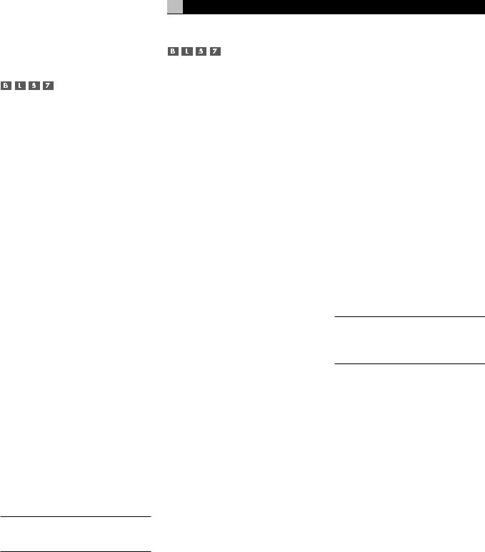
Other Settings
Temporary Speaker Level
The levels of all channels should be calibrated using the TEST TONE procedure during the initial setup of the RSP-1098. You can make a temporary change in the relative volume of the center, surround, center back, or subwoofer channels using buttons on the remote control or the front panel controls. These temporary adjustments only remain in effect until a different input is selected or until the RSP-1098 is turned off.
To adjust speaker levels using the remote:
1.Press a selection button on the remote to select a channel (or pair of channels) for adjustment. Press the C button to adjust the CENTER channel. Press the S button to adjust the SUBWOOFER channel. Press the R button to adjust the rear SURROUND or CENTER BACK channels (each press of the R button toggles between the SURROUND channels and the CENTER BACK channels). The selected speaker and its current setting appear briefly in the display.
2.Use the UP or DOWN buttons on the remote to adjust the output level of the selected channel(s).
To adjust speaker levels from the front panel.
1.Press the SPEAKER button repeatedly until the desired speaker or group of speakers is displayed.
2.Rotate the FUNCTION knob to change the level of the selected speaker.
NOTE: If no level adjustment is made for 5 seconds, the levels revert to the default calibrated settings.
As you select a speaker in the above adjustments, you may notice an addition choice, “group delay”. See the following for an explanation of this feature.
29
Temporary Group Delay
The SPEAKER adjustments (described above) can also be used to make a temporary adjustment to the group delay or “lip-synch” delay. Group delay delays the overall audio signal (to all speakers) by a specified amount to correct for situations where the video and audio signals are out of synch. This can occur with upconverted digital TV signals or when trying to match a radio broadcast with the video from a sports event. The settings range from 0 to 500 milliseconds in 5 ms increments.
Like the speaker settings, this is a temporary adjustment that overrides the permanent default setting for a video source until a different input source is selected or the unit is turned off.
To adjust group delay using the remote:
1.Press the C button on the remote twice.
2.Use the UP or DOWN buttons on the remote to adjust the amount of delay applied to all channels.
To adjust the group delay from the front panel:
1.Press the SPEAKER button repeatedly until you reach the GROUP DELAY option.
2.Rotate the FUNCTION control to adjust the amount of delay applied to all channels.
Dynamic Range 


Dolby Digital recordings are capable of wide dynamic range (the difference between the softest and loudest sounds). In some cases, this may tax amplifiers and/or speakers. In other cases, you may want to reduce the dynamic range when listening at low volume levels. This is particularly useful in order to keep dialog loud enough to be intelligible while avoiding excessively loud sound effects. Dolby Digital dynamic compensation is a sophisticated feature that allows you to adjust the dynamic range while still preserving fidelity. The actual amount of compression relies on instructions embedded in the Dolby Digital recording and varies to best suit the specific program content.
English
There are three dynamic range settings available for Dolby Digital recordings:
MAX: full dynamic range
MID: slightly reduced dynamic range, roughly comparable to the signal from a compact disc
MIN: more heavily reduced dynamic range, but still comparable to the signal from a typical VHS Hi-Fi recording.
To adjust dynamic range using the remote:
Press the DYN button repeatedly until the desired setting appears in the OSD/TFT screen. This setting remains in effect for all Dolby Digital program material until it is changed.
To adjust dynamic range from the front panel:
1.While playing a Dolby Digital source, press the MODE button twice
2.Rotate the FUNCTION control to select the dynamic range setting.
NOTE: The dynamic range compensation feature is only available in Dolby Digital mode. The setting is ignored with all other types of recordings.
Contour/Tone Settings 

The contour adjustment (available only the remote control) changes the high or low frequency content at the frequency extremes. The settings can be adjusted up or down by a maximum of 6dB. Adjustments to the contour settings are permanent; they remain in effect until they are readjusted.
Changing the high frequency contour (HF) increases or decreases the treble. Changing the low frequency contour (LF) increases or decreases the bass content. The settings are shown on the OSD and/or TFT displays as you adjust them.
To adjust the contour settings:
1.Press the TONE button on the remote. Either LF or HF appears in the OSD/TFT displays, depending on which adjustment is currently active. Press the TONE button again to toggle to the other adjustment.
2.Press the UP/DOWN buttons on the remote to increase or decrease the setting. The display will revert to normal operation following several seconds of inactivity.

RSP-1098 Surround Sound Processor |
30 |
More extensive contour adjustments for all speakers or for any group of speakers (front, center, surround, etc.) can also be made from the Contour Settings OSD menu in the Setup section of this manual.
NOTE: The tone adjustments are available for all surround modes and inputs, except the MULTI input and analog bypass mode.
Cinema EQ 
The EQ button (remote only) activates or deactivates a special CINEMA EQ setting. This equalization may be desirable for playback of movie source material to compensate for the acoustic differences between a commercial cinema and a home theater environment by reducing the high-frequency content.
The EQ setting is independent for each source input. Using the button only changes the setting for the currently active source input.
Zone 2 Operation
The RSP-1098 provides Zone 2 multi-room capability, allowing you to enjoy music and operate the system from a second room. From the remote location, you can select a source component (independent from the source playing in the main room), adjust the volume level in the remote zone, and operate the source components.
To use the Zone 2 capability, you need additional components: a pair of speakers installed in the remote zone, an amplifier to drive them, an optional TV monitor for video signals, and a third-party IR repeater system.
Zone 2 can be controlled from the main room using RSP-1098’s front panel PATH button. Operation from the remote zone requires the installation of an infrared repeater system (Xantech, Niles, etc.) which relays infrared remote control commands from Zone 2 to the ZONE REM IN connector on the back of the RSP-1098.
Several points to keep in mind about the Zone 2 function:
•There are two options for the Zone 2 output level, selectable from the OSD configuration menu. VARIABLE output provides full adjustment of the volume level. FIXED output disables the Zone 2 volume control with the output permanently set to a specified level.
This might be useful for sending a line level signal to a preamp or integrated amp with its own volume control or to a distribution amplifier with multiple volume controls.
•The RR-1050 remote control supplied with the RSP-1098 will operate Zone 2 if used with a repeater system from the remote zone. It can also be programmed to operate Rotel source components via the RSP-1098's IR OUT jack.
•Any source component connected to the RSP-1098's analog inputs can be sent to the Zone 2 outputs. ZONE 2 operates independently of the main room. You can select a different source or adjust Zone 2 volume without affecting the MAIN outputs in any way.
•Avoid sending the same infrared command to the RSP-1098 front panel sensor and a Zone 2 repeater at the same time. This means that Zone 2 must be in a different room from the RSP-1098.
Zone 2 Power On/Off
Operation 
Once master power is applied to the unit by pressing the rear panel POWER switch button, the RSP-1098 provides independent power on/off operation for both zones. Pressing the remote control ON/OFF buttons in the main room activates or deactivates the RSP-1098 in the main room only and has no effect on Zone 2. Conversely, activating or deactivating Zone 2 has no effect on the main listening room. However, placing the rear panel master POWER switch in the OFF position completely shuts off the unit, for both zones.
NOTE: For proper power on and off operation with Zone 2, the RSP-1098’s power mode should be set to the factory default DIRECT setting or to the STANDBY setting using the Other Options menu described in the Setup section of this manual.
Controlling Zone 2 from the Front Panel
You can control Zone 2 from the front panel of the RSP-1098 – activate or deactivate Zone 2, change input sources, and adjust the volume. Controlling Zone 2 from the front panel is accomplished by pressing the PATH repeatedly until ZONE 2 status information is displayed on the OSD and/or TFT screens. This temporarily puts the RSP-1098 in Zone 2 control
mode. When the Zone 2 status is displayed, the OSD and/or TFT screens show the current source selection and volume in Zone 2 for five seconds, during which time you can use the front panel VOLUME control and FUNCTION knob to change the ZONE 2 settings.
To change the Zone 2 input source:
1.Press the front panel PATH button repeatedly until the Zone 2 status appears in the OSD and/or TFT screen.
2.Within 5 seconds, rotate the FUNCTION knob to select a new source for Zone 2. The name of the selected source appears in the display. Selecting OFF instead of a an input deactivates Zone 2.
3.Following 5 seconds with no commands, the RSP-1098 reverts to normal operation.
To change the Zone 2 volume:
1.Press the front panel PATH button repeatedly until the Zone 2 status appears in the OSD and/or TFT screen. Make sure that Zone 2 is ON.
2.Within 5 seconds, adjust the volume control to change the Zone 2 output level. The new setting appears in the display.
3.Following 5 seconds with no commands, the RSP-1098 reverts to normal operation.
Controlling Zone 2 from the Remote Location 


With a properly configured IR repeater system, you have full control of Zone 2 using an RR-1050 remote from the Zone 2 location. You can select and operate a source, adjust the volume, and turn Zone 2 on or off. Whatever commands you send from the RR-1050 will change Zone 2 and only Zone 2, just as if you were controlling a totally independent audio system in that room. These changes will have no effect on the main listening room.
To turn Zone 2 on or off, press the ON/OFF buttons on the remote. To adjust the volume in Zone 2, press the VOLUME buttons on the remote. To select a different analog input source, press one of the DEVICE/INPUT buttons on the remote.
NOTE: The volume adjustment is only available if the Zone 2 outputs are configured to use VARIABLE levels. With FIXED levels, the volume control for Zone 2 is disabled.
 Loading...