


Owner’s manual
Manuel d’utilisation
RSX-1058
Surround Sound Receiver
Ampli-tuner Surround
|
|
|
|
|
|
|
|
|
|
|
|
|
|
|
|
|
|
|
|
|
|
|
|
|
|
|
|
|
|
|
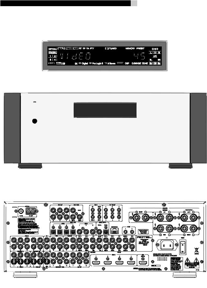
RSX-1058 Surround Sound Receiver |
2 |
> 10 cm |
> 4 in |
|
|
|
|
> 10 cm |
> 10 cm |
|
|
> 4 in |
> 4 in |
> 10 cm > 4 in
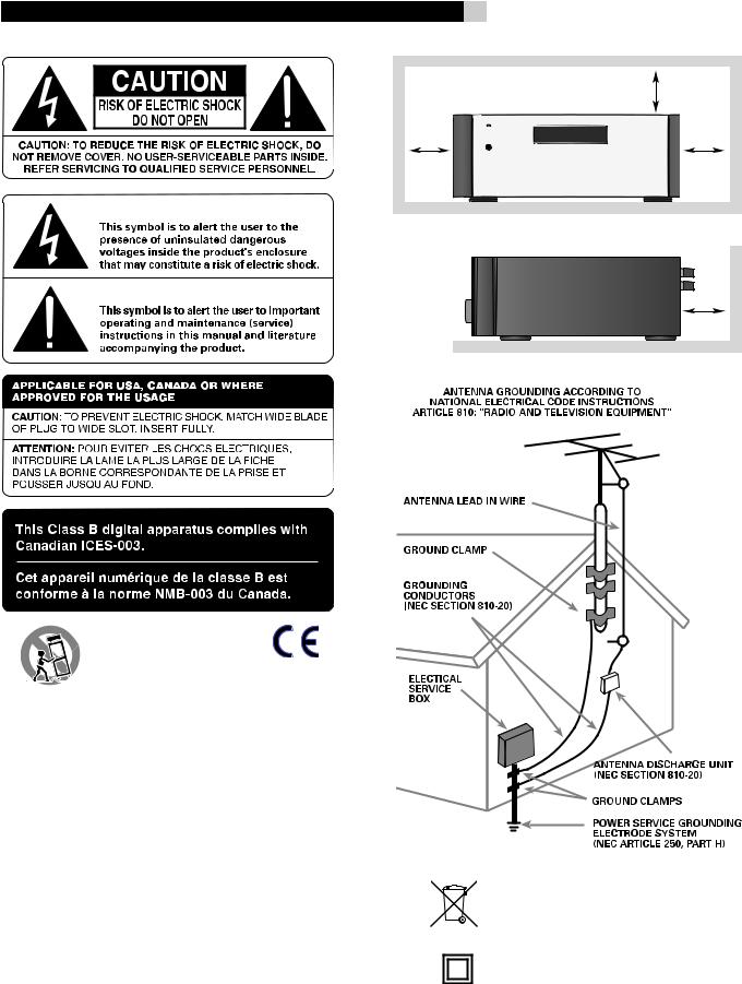
Rotelproductsaredesignedtocomplywithinternationaldirectivesonthe Restriction of Hazardous Substances (RoHS) in electrical and electronic equipment and the disposal of Waste Electrical and Electronic Equipment (WEEE). The crossed wheelie bin symbol indicates compliance and that the products must be appropriately recycled or processed in accordance with these directives.
This symbol means that this unit is double insulated. An earth or ground connection is not required.

3 |
English |
Notice
The COMPUTER I/Oconnectionshould be handled by authorized persons only.
FCC Information
This equipment has been tested and found to comply withthe limits fora Class B digitaldevice, pursuant to Part 15 of the FCC Rules. These limits are designed to provide reasonable protection against harmful interference in a residential installation. This equipment generates, uses and can radiate radio frequency energy and, if not installed and used in accordance with the instruction, may cause harmful interference to radio communications.
However, there is no guarantee that interference will not occur in a particular installation. If this equipment does cause harmful interference to radio or television reception, which can be determined by turning the equipment off and on, the user is encouraged to try to correct the interference by one or more of the following measures:
•Reorient or relocate the receiving antenna.(TV, radio, etc.)
•Increase the separation between the equipment and receiver
•Connect the equipment to an outlet on circuit different from that to which the receiver is connected.
•Consult the dealer or an experienced radio/TV technician for additional help.
Caution
Thisdevicecomplieswithpart15oftheFCCRulesoperationissubjecttothefollowingtoconditions: (1) This device may not cause harmful interference, and (2) this device must accept any interference received, including interference that may cause undesired operation.
NOTE TO CATV SYSTEM INSTALLER: Call the CATV system or antenna installer’sattentiontoArticle820-40oftheNEC.Thisprovidesguidelinesforpropergrounding and,inparticular,specifiesthatthecablegroundshallbeconnectedtothegroundingsystemof the building, as close to the point of cable entry as practical. See installation diagram.
NOTE: This equipment has been tested and found to comply with the limits for a Class B digital device, pursuant to Part 15 of the FCC Rules. These limits are designed to provide reasonable protection against interference in a residential installation. This equipment generates and can radiate radio frequency energy and, if not installed and used in accordance with the instructions,maycauseinterferencetoradioorTVcommunications.Thereisnoguaranteethat interferencewillnotoccurinaparticularinstallation.Ifthisequipmentdoescauseinterference to radio or television reception, which can be determined by turning the equipment off and on, try to correct the interference by one or more of the following measures:
•Reorient or relocate the receiving antenna.
•Increase the separation between the unit and the television tuner.
•Connect the unit to an AC power outlet on a different electrical circuit.
•Consult your authorized Rotel retailer for assistance.
Important Safety Instructions
WARNING: There are no user serviceable parts inside. Refer all servicing to qualified service personnel.
WARNING: To reduce the risk of fire or electric shock, do not expose the unit to moisture or water. Do not expose the unit to dripping or splashing. Do not place objects filled with liquids, such as vases, on the unit. Do not allow foreign objects to get into the enclosure. If the unit is exposed to moisture, or a foreign object gets into the enclosure, immediately disconnect the power cord from the wall. Take the unit to a qualified service person for inspection and necessary repairs.
Read all the instructions before connecting or operating the component. Keep this manual so you can refer to these safety instructions.
Heed all warnings and safety information in these instructions and on the product itself. Follow all operating instructions.
Clean the enclosure only with a dry cloth or a vacuum cleaner. Do not use this unit near water.
You must allow a minimum 10 cm or 4 inches of unobstructed clearance around the unit. Do not place the unit on a bed, sofa, rug, or similar surface that could block the ventilation openings. If the unit is placed in a bookcase or cabinet, there must be ventilation of the cabinet to allow proper cooling.
Keep the component away from radiators, heat registers, stoves, or any other appliance that produces heat.
Theunitmustbeconnectedtoapowersupplyonlyofthetypeandvoltagespecifiedontherear panel. (USA: 120 V/60Hz, EC: 230V/50Hz)
Connect the component to the power outlet only with the supplied power supply cable or an exact equivalent. Do not modify the supplied cable. A polarized plug has two blades, with one wider than the other. A grounding plug has two blades plus a third grounding prong. These are providedforyoursafety.Donotdefeatgroundingand/orpolarizationsafetyprovisions.Ifthe supplied plug does not fit your outlet, please consult an electrician for replacement of the obsolete outlet. Do not use extension cords.
The main plug of the power cordset is a disconnect device of the apparatus. In order to completely disconnect the apparatus from the supply mains, the main plug of the power cordset should be unplugged from the mains (AC) outlet. The stand-by LED indicator will not be lit up to show the power cord is unplugged.
Do not route the power cord where it will be crushed, pinched, bent, exposed to heat, or damaged in any way. Pay particular attention to the power cord at the plug and where the cord exits the back of the unit.
Thepowercordshouldbeunpluggedfromthewalloutletduringalightningstormoriftheunit is to be left unused for a long period of time.
Use only accessories specified by the manufacturer.
Use only with a cart, stand, rack, bracket or shelf system recommended by Rotel. Use caution when moving the unit in a stand or rack to avoid injury from a tip-over.
Use Class 2 wiring for speaker connections to ensure proper installation and minimize the risk of electrical shock.
Immediately stop using the component and have it inspected and/or serviced by a qualified service agency if:
•The power supply cord or plug has been damaged.
•Objects have fallen or liquid has been spilled into the unit.
•The unit has been exposed to rain.
•The unit shows signs of improper operation
•The unit has been dropped or damaged in any way
WARNING: The master power switch is located on the rear panel. The unit must be located in the open area allowing unobstructed access to the main power switch.
RSX-1058 Surround Sound Receiver |
4 |
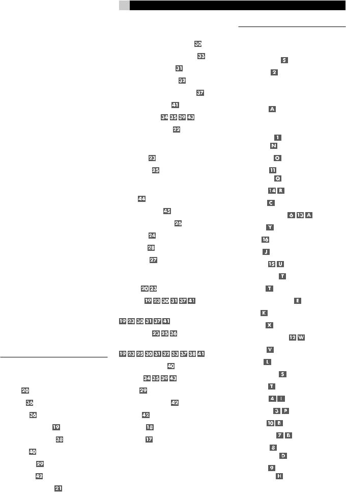
1:Controls and Connections Commandes et Branchements
|
|
|
|
|
|
|
|
|
|
|
|
|
|
|
|
|
|
|
|
|
|
|
|
|
|
|
|
|
|
|
|
|
|
|
|
|
|
|
|
|
|
|
|
|
|
|
|
|
|
|
|
|
|
|
|
|
|
|
|
|
|
|
|
|
5 |
English |
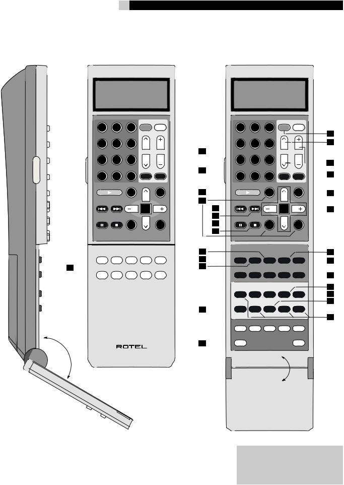
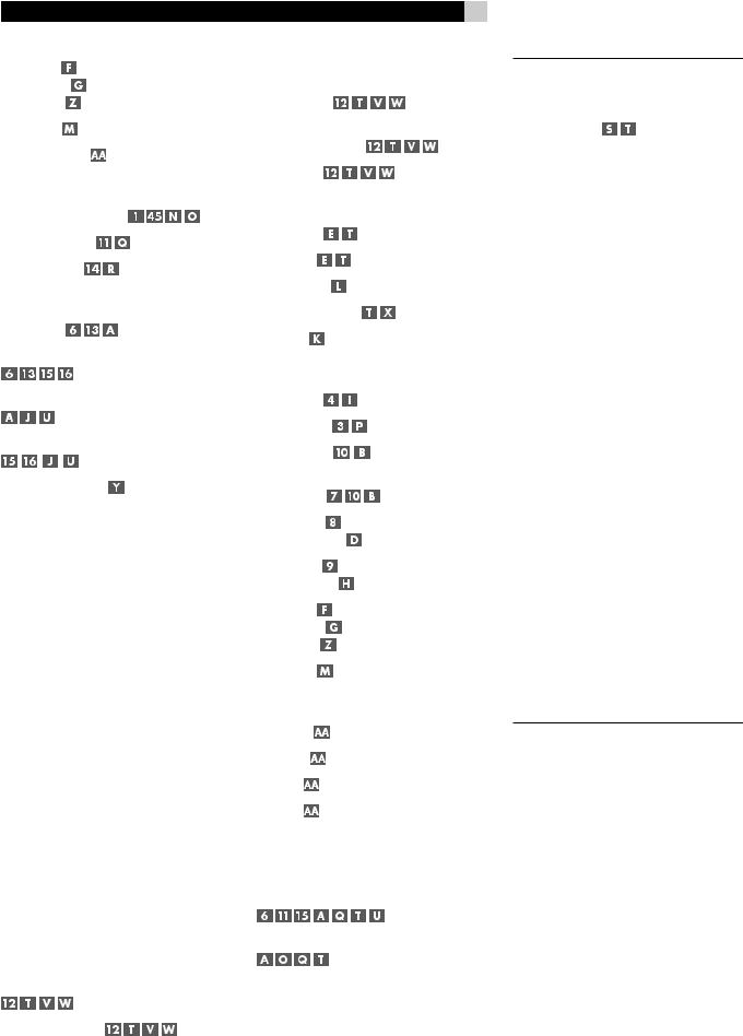
2:RR-1060 Remote Télécommande RR-1060
LIGHT
1 |
2 |
3 |
POWER |
|
ON |
OFF |
|||
4 |
5 |
6 |
|
|
|
|
|
CH |
VOL |
7 |
8 |
9 |
|
|
|
|
MEM |
SMART |
|
+10 |
0 |
X |
|
|
SMT |
MUTE |
|||
FRQ DIRECT |
GUIDE |
|
MENU |
|
|
|
|
||
|
|
C |
|
M |
TUNE |
PRESET |
CTR |
|
OSD |
|
|
|
||
|
|
|
ENT |
|
FM MONO |
BAND |
SEARCH- |
|
SEARCH+ |
|
|
S |
|
R |
|
|
SUB |
|
SUR |
AUD CD TUN TAPE EXT
DEVICE / INPUT
V1 |
V2 |
V3 |
V4 |
V5 |
RR-1060
|
|
1 |
2 |
3 |
POWER |
|
|
|
|
ON |
OFF |
|
|||
|
|
|
|
|
|
|
|
|
|
4 |
5 |
6 |
|
|
|
|
|
|
|
|
|||
|
|
|
|
|
CH |
VOL |
|
|
|
7 |
8 |
9 |
|
|
|
|
|
|
|
|
|
|
|
|
|
+10 |
|
MEM |
SMART |
|
|
|
|
0 |
X |
SMT |
MUTE |
||
|
|
|
|||||
|
|
FRQ DIRECT |
GUIDE |
|
MENU |
|
|
|
|
|
|
|
|
||
|
|
|
C |
|
M |
|
|
|
|
TUNE |
PRESET |
CTR |
|
OSD |
|
|
|
|
|
|
|
||
|
|
|
|
ENT |
|
|
|
|
|
FM MONO |
BAND |
SEARCH- |
|
SEARCH+ |
|
|
|
|
|
||||
|
|
|
S |
|
R |
|
|
|
|
|
|
|
|
||
|
|
|
SUB |
|
SUR |
|
|
|
|
CD |
DISC2 |
DISC3 |
DISC4 |
DISC5 |
|
|
|
DISC1 |
|
||||
|
EQ |
DYN |
REC |
ZONE |
SUR+ |
||
|
|
||||||
|
PROG |
RANDOM REPEAT |
DISC- |
DISC+ |
|
||
|
|
|
|||||
|
|
2CH |
PL C |
PL M |
5CH |
7CH |
|
|
|
DVD |
DIGEST |
TITLE |
P-SCAN |
OPEN |
|
|
|
|
|
|
|
|
|
|
|
DISPLAY |
AUDIO |
ANGLE |
SBTITLE |
ZOOM |
|
|
|
|
|||||
|
|
DISP |
TAPE2 |
PHONO |
TONE |
D-SLT |
|
|
|
RESUME REPEAT |
A - B |
GOTO |
SLOW |
|
|
|
|
|
|||||
|
SCAN |
PTY |
P-TUN |
TP |
TA |
|
|
|
|
INPUT 1 |
INPUT 2 |
INPUT 3 |
TV/VCR |
RECORD |
|
|
|
|
|
|
|
|
|
|
|
ASPECT |
DISP |
PIP |
POP |
OUTPUT |
|
|
|
POWER |
|
|
|
SETUP |
|
Turn off the RSX-1058 and the entire system before making connections!
Éteignez toujours le RSX-1058 et tout le système avant d’effectuer le moindre branchement !
RSX-1058 Surround Sound Receiver |
6 |
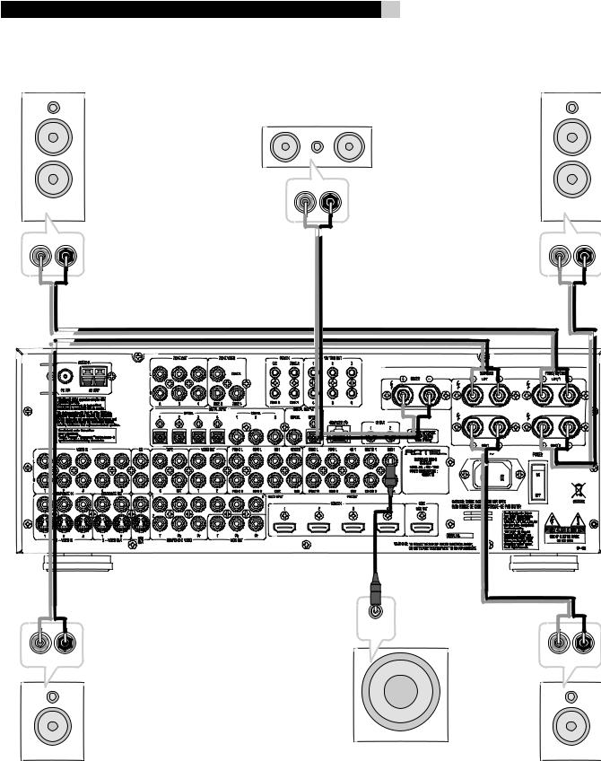
3:Connecting the Speakers Branchement des enceintes acoustiques
7 |
English |
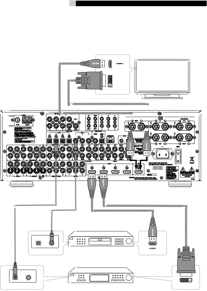
4:Digital Video Connections Branchement des sources vidéo
|
|

RSX-1058 Surround Sound Receiver |
8 |
5:TV Analog Connections Branchements d’un téléviseur
|
|
|
|
|
|
|
|
|
|
|
|
|
|
|
|
|
|
|
|
|
|
6:DVD Player Analog Connections
Branchements d’un lecteur de DVD en liaison analogique
|
|
|
|
|
|
|
|
|
|
|
|
||
|
|
|||||
9 |
|
|
|
|
|
|
|
|
|
|
|
|
|
|
|
|
|
|
|
|
|
|
|
|
|
English |
||||||
7: DVD-A or SACD Player Connections |
|
|
|
|
|
|
|
|
|
|
|
|
|
|
|
|
|
|
|
|
|
|
|
|
|
|
|
|
|
|
|
|
Branchements d’un lecteur de DVD-Audio ou SACD |
|
|
|
|
|
|
|
|
|
|
|
|
|
|
|
|
|
|
|
|
|
|
|
|
|
|
|
|
||||
|
|
|
|
|
|
|
|
|
|
|
|
|
|
|
|
|
|
|
|
|
|
|
|
|
|
|
|
|
|
|
|
|
|
|
|
|
|
|
|
|
|
|
|
|
|
|
|
|
|
|
|
|
|
|
|
|
|
|
|
|
|
|
|
|
|
|
|
|
|
|
|
|
|
|
|
|
|
|
|
|
|
|
|
|
|
|
|
|
|
|
|
|
|
|
|
|
|
|
|
|
|
|
|
|
|
|
|
|
|
|
|
|
|
|
|
|
|
|
|
|
|
|
|
|
|
|
|
|
|
|
|
|
|
|
|
|
|
|
|
|
|
|
|
|
|
|
|
|
|
|
|
|
|
|
|
|
|
|
|
|
|
|
|
|
|
|
|
|
|
|
|
|
|
|
|
|
|
|
|
|
|
|
|
|
|
|
|
|
|
|
|
|
|
|
|
|
|
|
|
|
|
|
|
|
|
|
|
|
|
|
|
|
|
|
|
|
|
|
|
|
|
|
|
|
|
|
|
|
|
|
|
|
|
|
|
|
|
|
|
|
|
|
|
|
|
|
|
|
|
|
|
|
|
|
|
|
|
|
|
|
|
|
|
|
|
|
|
|
|
|
|
|
|
|
|
|
|
|
|
|
|
|
|
|
|
|
|
|
|
|
|
|
|
|
|
|
|
|
|
|
|
|
|
|
|
|
|
|
|
|
|
|
|
|
|
|
|
|
|
|
|
|
|
|
|
|
|
|
|
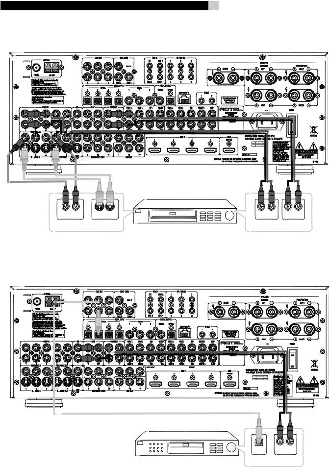
8:Cable, Satellite, or HDTV Analog Connections Branchements d’un décodeur câble, satellite ou HDTV
|
|
|
|
|
|
|
|
|
|
|
|
|
|
||||
RSX-1058 Surround Sound Receiver |
10 |
9:VCR Analog Connections
Branchement d’un magnétoscope (VCR) en liaison analogique
10:CD Player/CDR Recorder Connections Branchement d’un lecteur/enregistreur de CD/CD-R
|
|
|
|
11 |
English |
11:Audio Recorder Connections Branchements d’un enregistreur audio
|
|
|
|
|
|
|
|
|
|
||
|
|
|
|
|
|
12:AM and FM Antennae Connections Branchements des antennes radio AM et FM
RSX-1058 Surround Sound Receiver
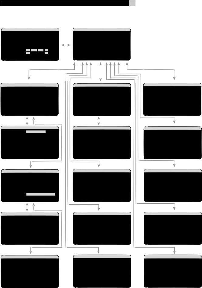
13: On-Screen Menus
12
Contents |
|
Boxed numbers refer to RSX-1058 illustration. |
|
Boxed letters refer to RR-1060 illustration. |
|
FCC Information.................................................. |
3 |
Caution............................................................... |
3 |
Important Safety Instructions.................. |
3 |
1: Controls and Connections ................................ |
4 |
2: RR-1060 Remote............................................. |
5 |
3: Connecting the Speakers................................. |
6 |
4: Digital Video Connections................................ |
7 |
5: TV Analog Connections.................................... |
8 |
6: DVD Player Analog Connections....................... |
8 |
7: DVD-A or SACD Player Connections.................. |
9 |
8: Cable, Satellite, or HDTV Analog Connections... |
9 |
9: VCR Analog Connections................................ |
10 |
10: CD Player/CDR Recorder Connections .......... |
10 |
11: Audio Recorder Connections......................... |
11 |
12: AM and FM Antennae Connections............... |
11 |
13: On-Screen Menus ........................................ |
12 |
About Rotel.......................................... |
15 |
Getting Started..................................... |
15 |
Key Features..................................................... |
15 |
Unpacking ........................................................ |
16 |
Placement ........................................................ |
16 |
CONNECTIONS |
16 |
Analog Audio Inputs & Outputs ............. |
16 |
CD Inputs .................................................... |
16 |
TAPE Inputs ................................................. |
16 |
TAPE Outputs .............................................. |
16 |
VIDEO 1–5 Audio Inputs ............................. |
16 |
VIDEO 1–2 Audio Outputs ........................... |
17 |
MULTI Inputs ............................................. |
17 |
Speaker Outputs ......................................... |
17 |
Preamp Outputs ......................................... |
17 |
ZONE 2–4 Audio Outputs ............................ |
17 |
13
Video Inputs & Outputs ........................ |
17 |
VIDEO 1–3 Composite Video Inputs ............ |
18 |
VIDEO 1–2 Composite Video Outputs .......... |
18 |
VIDEO 1–3 S-Video Inputs .......................... |
18 |
VIDEO 1–2 S-Video Outputs ....................... |
18 |
VIDEO 1–3 Component Video Inputs .......... |
18 |
VIDEO 1–4 HDMI Inputs ............................ |
18 |
TV Monitor Outputs .................. |
18 |
ZONE OUT Video Outputs ............................ |
19 |
Digital Audio Input & Outputs ............... |
19 |
Digital Inputs .............................................. |
19 |
Digital Outputs ............................................ |
19 |
Other Connections ................................ |
19 |
AC Input ..................................................... |
19 |
Master Power Switch ................................... |
19 |
12V TRIGGER Connections ........................... |
20 |
REM IN Jacks ............................................. |
20 |
IR OUT Jacks ............................................... |
20 |
Computer I/O ............................................. |
20 |
Making Connections ............................. |
20 |
CD Player ............................................. |
20 |
DVD Player .................. |
20 |
Cable, Satellite, HDTV Tuner |
21 |
.................................... |
|
Audio Recorder .............................. |
21 |
VCR or Digital Video Recorder |
21 |
........... |
|
DVD-A or SACD Player ................................ |
21 |
TV Monitor ............................... |
22 |
Speakers .................................................... |
22 |
Connecting a Subwoofer .............................. |
22 |
Amplifiers ................................................... |
23 |
AM Antenna ................................................ |
23 |
FM Antenna ............................................... |
23 |
English |
|
OPERATING THE RSX-1058 |
23 |
Front Panel Overview........................... |
23 |
Front-panel Display .................................... |
24 |
Remote Sensor ............................................ |
24 |
Remote Control Overview..................... |
24 |
Using the RR-1060 |
|
AUDIO Button ............................................. |
24 |
Overview of Buttons and Controls......... |
24 |
STANDBY Button |
|
POWER Button ............................................ |
24 |
ON/OFF Buttons ......................................... |
24 |
VOLUME Knob |
|
VOLUME Buttons ......................................... |
24 |
MUTE Buttons ....................................... |
24 |
LIGHT Button .............................................. |
24 |
DEVICE/INPUT Buttons ................... |
24 |
D-SLT Button ............................................... |
24 |
SEL Button .................................................. |
25 |
REC Button .................................................. |
25 |
ZONE Buttons ....................................... |
25 |
UP/DOWN Buttons ...................................... |
25 |
+/– Buttons ............................................... |
25 |
Speaker Selection Buttons ........................... |
25 |
EQ Button ................................................... |
25 |
TONE Button ............................................... |
25 |
Surround Mode Buttons ........................ |
25 |
SUR+ Button ............................................... |
25 |
DYN Button ................................................. |
25 |
MENU/OSD Button ...................................... |
25 |
ENTER Button .............................................. |
25 |
BAND Buttons ....................................... |
25 |
TUNING Buttons .................................... |
25 |
MEM Buttons ........................................ |
25 |
NUMERIC Buttons ................................. |
25 |
DIRECT Button |
|
FRQ DIRECT Button ..................................... |
25 |
MONO Button |
|
FM MONO Button ........................................ |
25 |
RSX-1058 Surround Sound Receiver |
|
TUNE Button |
|
PRESET Button |
|
P-TUN Button .............................................. |
25 |
SCAN Button ............................................... |
25 |
RDS/RBDS Buttons ..................................... |
26 |
Basic Operations................................... |
26 |
Power and Standby On/Off ...... |
26 |
Volume Adjustments ............................. |
26 |
Muting the Sound ................................. |
26 |
Selecting Inputs.................................... |
26 |
Input Buttons ................................. |
26 |
Selecting a Source Input from the Front Panel |
|
................................................ |
27 |
Selecting a Source from the Remote |
|
....................................................... |
27 |
Selecting the Same Input for all Outputs |
|
............................................... |
27 |
Selecting Digital Inputs ............................... |
27 |
Overview of Surround Formats.............. |
27 |
Dolby Surround |
|
Dolby Pro Logic II.............................................. |
27 |
Dolby Digital..................................................... |
28 |
DTS5.1 |
|
DTS 96/24........................................................ |
28 |
DTS Neo:6......................................................... |
28 |
Dolby Digital Surround EX |
|
DTS-ES6.1 and 7.1 Channel Surround................. |
28 |
Dolby Pro Logic IIx |
|
6.1 and 7.1 Channel Surround ........................... |
29 |
Rotel XS |
|
6.1 and 7.1 Channel Surround ........................... |
29 |
DSP Music Modes .............................................. |
29 |
2Ch/5Ch/7Ch Stereo Formats........................... |
29 |
Other Digital Formats ........................... |
29 |
Automatic Surround Modes ................... |
30 |
Manually Selecting Surround Modes...... |
30 |
Dolby Digital 5.1 discs |
|
Dolby Digital Surround EX discs |
|
................................................ |
30 |
Dolby Digital 2.0 discs .............. |
31 |
|
14 |
DTS 5.1 discs |
|
DTS 96/24 discs |
|
DTS-ES 6.1 discs ....................... |
31 |
Digital Stereo discs |
|
(PCM, MP3, and HDCD) ............ |
31 |
Analog Stereo .......................... |
32 |
Other Settings...................................... |
32 |
Speaker Level ....................................... |
32 |
Group Delay ......................................... |
33 |
Dynamic Range .......................................... |
33 |
Contour/Tone Settings .......................... |
33 |
Cinema EQ .................................................. |
33 |
Tuner Controls...................................... |
33 |
BAND Buttons ...................................... |
34 |
TUNING Buttons ................................... |
34 |
MEMORY Button .................................. |
34 |
NUMERIC Buttons: |
|
Station Presets .............................. |
34 |
DIRECT Button |
|
FRQ DIRECT Button ................................... |
34 |
MONO Button |
|
FM MONO Button ....................................... |
35 |
TUNE Button |
|
PRESET Button |
|
P-TUN Button ............................................. |
35 |
SCAN Button ............................................... |
35 |
RDS and RBDS Tuning ........................... |
35 |
DISP Button ................................................ |
35 |
PTY Button ................................................. |
35 |
TP Button .................................................... |
36 |
TA Button .................................................... |
36 |
Zones 2–4 Operation............................ |
36 |
Zones 2–4 Power On/Off ................................ |
36 |
Controlling Zones 2–4 from the Main Room |
|
.............................. |
36 |
Controlling Zones 2–4 from the Remote Location |
|
................................................ |
37 |
SETUP |
37 |
Menu Basics......................................... |
37 |
Navigation Buttons ............................... |
37 |
System Status.................................................... |
37 |
Main Menu........................................................ |
38 |
Configuring Inputs................................ |
38 |
Input Setup....................................................... |
38 |
Multi Input Setup .............................................. |
39 |
Dolby Pro Logic IIx............................................ |
39 |
DTS Neo:6........................................................ |
40 |
Configuring Speakers and Audio............ |
40 |
Understanding Speaker Configuration.............. |
40 |
Speaker Setup................................................... |
41 |
Advance Speaker Setup..................................... |
41 |
Subwoofer Setup............................................... |
42 |
Test Tone........................................................... |
43 |
Delay Setup...................................................... |
43 |
Contour Setup.................................................. |
44 |
Miscellaneous Settings.......................... |
44 |
Other Options................................................... |
44 |
Video/HDMI Setup............................................ |
45 |
Zones 2–4 Setup .............................................. |
45 |
Default Setup.................................................... |
45 |
MORE INFORMATION |
46 |
Troubleshooting.................................... |
46 |
Specifications ....................................... |
47 |
Audio................................................................ |
47 |
Video................................................................ |
47 |
FM Tuner........................................................... |
47 |
AM Tuner.......................................................... |
47 |
General............................................................. |
47 |

About Rotel
A family whose passionate interest in music led them to manufacture high fidelity components of uncompromising quality founded Rotel 45 years ago. Through the years that passion has remained undiminished and the family goal of providing exceptional value for audiophiles and music lovers regardless of their budget, is shared by all Rotel employees.
The engineers work as a close team, listening to, and fine tuning each new product until it reachestheirexactingmusicalstandards.They are free to choose components from around the world in order to make that product the best they can. You are likely to find capacitors from the United Kingdom and Germany, semi conductors from Japan or the United States, while toroidal power transformers are manufactured in Rotel’s own factory.
Rotel’s reputation for excellence has been earned through hundreds of good reviews and awards from the most respected reviewers in the industry, who listen to music every day. Their comments keep the company true to its goal - the pursuit of equipment that is musical, reliable and affordable.
All of us at Rotel, thank you for buying this product and hope it will bring you many years of enjoyment.
“DTS”, “DTS-ES Extended Surround”, “DTS ES® Matrix 6.1”, and “DTS ES® Discrete 6.1”, and “DTS Neo:6®”are trademarks of Digital Theater Systems, Inc.
Manufactured under license from Dolby Laboratories. “Dolby”, “Pro Logic”, and the double-D symbol are trademarks of Dolby Laboratories.
 , HDCD®, High Definition Compatible Digital® and Pacific Microsonics™ are either registered trademarks or trademarks of Pacific Microsonics, Inc. in the United States and/or other countries. HDCD system manufactured under license from Pacific Microsonics, Inc. This product is covered by one or more of the following: In the USA:
5,479,168, 5,638,074, 5,640,161, 5,808,574, 5,838,274, 5,854,600, 5,864,311, 5,872,531, and in Australia: 669114. Other patents pending.
15 |
English |
Getting Started
Thank you for purchasing the Rotel RSX-1058 Surround Sound Receiver. The RSX-1058 is four products in one:
1.A digital audio/video processor for a wide range of formats including Dolby Surround®, Dolby Digital®, DTS® and HDCD® source material.
2.A full-featured audio/video control center for analog and digital source components.
3.A high-quality AM/FM tuner with RDS capability.
4.A 5-channel power amplifier to drive two front speakers (or two center back speakers), a center channel speaker, and two rear surround speakers.
Key Features
•Rotel’sBalancedDesignConceptcombines advanced circuit board layout, comprehensive parts evaluation, and extensive listening tests for superior sound and long term reliability.
•Dolby® ProLogicIIx®decoding(for5.1,6.1, and 7.1 channel systems) with improved separation and frequency response for Dolby Surround® matrix encoded recordings. Can be optimized for Music or Cinema sources, Pro Logic® or Games.
•Automatic Dolby Digital® decoding Dolby Digital® 2.0, Dolby Digital® 5.1, and Dolby Digital Surround EX® recordings.
•Automatic decoding for DTS® 5.1 channel, DTS-ES® Matrix 6.1 channel, DTS-ES® Discrete 6.1 channel, and DTS 96/24 digital recordings.
•Rotel XS (eXtended Surround) automatically ensures proper decoding and optimum performance from any multichannel digital signal on 6.1 and 7.1 channel systems. Always active in any system with center back speaker(s), Rotel XS even works with signals that would not otherwise activate the proper decoding (such as non-flagged DTS-ES and Dolby Surround EX discs) or for which there is no extended surround decoder (such as DTS 5.1, Dolby Digital 5.1, and even Dolby Pro Logic II decoded Dolby Digital 2.0 recordings).
•DTS® Neo:6® Surround modes for deriving surround channels for 5.1, 6.1 or 7.1 channel systems from 2-channel stereo or matrix surround recordings. Can be optimized for Music or Cinema sources.
•Automatic HDCD® decoding for signals from High Definition Compatible Digital® compact discs.
•DVD-A high-resolution multichannel audio signals are automatically detected when using an HDMI input connection.
•Surround modes for playback of surround sound material on 2 channel and 3 channel systems for total compatibility.
•Automatic decoding of digital signals from MP3 (MPEG-1 Audio Layer 3) players.
•Analoginputandoutputvideoconnections for use with Composite video, S-Video, and Component Video signals, including conversion to Component Video output.
•HDMI (Ver. 1.1) switching for digital video signals up to 1080p and downscaling from 1080i to 480p/576p. Compatible with DVI components with HDMI-DVI adapter.
•Optical digital, coax digital, and analog input and output audio connections.
•Five built-in amplifier channels, each delivering 75 watts (all channels driven).
•AM/FM tuner with 30 station presets, direct access tuning, and auto-tuning.
•RDS (Radio Data Systems) and RBDS (Radio Broadcast Data Service) capability.
•Zone 2, 3, and 4 outputs with independent input selection and volume adjustments for multi-zone custom installations along with IR-repeater capability for operation from the remote zone.
•MULTI Input for outboard adapter and future upgradeabilty
•User friendly ON-SCREEN DISPLAY with programmable labels for video components. Choice of languages.
•Universal learning remote control to operate the RSX-1058 and other components.
•Upgradeable microprocessor software to accommodate future upgrades.

RSX-1058 Surround Sound Receiver
Unpacking
Remove the unit carefully from its packing. Find the remote control and other accessories. Save the box as it will protect the RSX-1058 if you move or need to return it for maintenance.
Placement
Place the RSX-1058 on a solid, level surface away from sunlight, heat, moisture, or vibration. Make sure that the shelf can support the weight of the unit.
Place the RSX-1058 close to the other components in your system and, if possible, on its own shelf. This will make initial hookup, and subsequent system changes easier.
The RSX-1058 can generate heat during normal operation. Do not block ventilation openings. Allow a minimum of 10 cm or 4 inches of unobstructed space around the unit. If installed in a cabinet, make sure that there is adequate ventilation.
Don’t stack other components or objects on top of the RSX-1058. Don’t let any liquid fall into the unit.
16
CONNECTIONS
Although the RSX-1058’s rear panel looks daunting, connecting the unit to your system is straightforward. Each of the source components in the system are connected to the RSX-1058 inputs with a pair of standard RCA cables for analog audio, a video connection (Composite, S-Video, Component Video, and/or HDMI), and an optional digital audio cable (coax or optical).
NOTE: Surround formats like Dolby Digital and DTS are digital formats and the RSX-1058 can only decode them when a digital input signal is available. For this reason, you should always connect your DVD player’s digital outputs to the RSX-1058, using either the optical or coax inputs.
The outputs of RSX-1058 are sent to up to five speakers or to optional power amplifier(s) with standard RCA cables from preamp audio outputs. The video signal from the RSX-1058 is sent to the TV monitor using Composite video, S-Video, Component Video, and/or HDMI connections.
In addition, the RSX-1058 has MULTI input connections for a source component that does its own surround decoding, remote IR sensor inputs,and12Vtriggerconnectionsforremote turn-on of other Rotel components.
NOTE: Do NOT plug any system component into an AC source until all connections have been properly made.Video cables should have a 75 ohm impedance. The S/PDIF digital audio interface standard also specifies a 75 ohm impedance and all good digital cables adhere to this requirement. Do NOT substitute conventional audio interconnect cables for digital or videosignals.Standardaudiointerconnectswill pass these signals, but their limited bandwidth reduce performance.
When making signal connections, connect LEFT channels to LEFT channel jacks and RIGHT channels to RIGHT channel jacks. All RCA-type connections on the RSX-1058 follow these standard color codes:
Left channel audio: white RCA jack Right channel audio: red RCA jack Composite video: yellow RCA jack
NOTE: Each source input must be properly configured using the INPUT SETUP menu of the OSD menu system. We recommend going to this menu after connecting each source to configure it as desired. See Input Setup of the Setup section for information.
Analog Audio Inputs &
Outputs
The following connections are used for connecting analog audio signals to and from the RSX-1058. See the Making Connections topic for specific instructions on connecting each type of component.
NOTE: Normally, the RSX-1058 converts analog inputs to digital signals. All of the digital processingisavailableincludingbassmanagement,digitalcrossovers,speakerlevelanddelay settings,andanumbersurroundmodeoptions. Alternatively,thereisananalogbypasssurround mode that routes 2-ch and Multi Input analog signals directly to the Volume control and outputs, bypassing the digital processing entirely for pure analog stereo.
CD Inputs i
A left/right pair of RCA analog audio inputs for connecting a CD player.
TAPE Inputs 
A pair of RCA inputs, labeled TAPE IN, for connecting the left/right analog audio signals from an audio tape deck or recording device.
TAPE Outputs 
A pair of RCA inputs, labeled TAPE OUT, for sending left/right line level analog audio signals for recording on a tape deck or recording device.
NOTE: These outputs should be connected to the inputs of the same tape deck connected to the TAPE IN inputs.
VIDEO 1–5 Audio Inputs
Five pair of RCA inputs, labeled VIDEO IN 1–5, provide connections for left/right analog audio signals from five additional source components. These inputs have corresponding video inputs and are used for VCRs, satellite TV tuners, DVD players, etc. However,

they may also be used for additional audio only components, simply by omitting the corresponding video connections.
VIDEO 1–2 Audio Outputs 
Two pair of RCA jacks, labeled VIDEO OUT 1 & 2, provide connections for sending line level left and right analog audio signals for recording to a VCR.
These connections correspond to the VIDEO IN 1–2 connections. Make sure that you are consistent. If you hook up a particular VCR to the VIDEO 1 inputs, hook up the VIDEO 1 outputs to the same VCR.
NOTE: There are no analog audio outputs for VIDEO 3, 4 & 5. Therefore, in an elaborate system, hook up all of the VCRs and recording devices to VIDEO 1–2 and use VIDEO 3, 4 & 5 for playback only components.
NOTE:Video 1–2 can be used for audio-only tape decks, simply omitting the corresponding video connections.
MULTI Inputs 
A set of RCA inputs accept up to 7.1 channels of analog signals from a DVD-A or SACD player. There are inputs for FRONT L & R, CENTER, SUB, REAR L & R, and CENTER BACK (CB) 1 & 2.
These inputs bypass all digital processing in the RSX-1058 and are routed directly to the Volume control and outputs.
TherearetwosubwooferoptionsfortheMULTI input. Normally, the .1 channel input is passed through directly to the subwoofer output. An optional bass redirect feature duplicates the 7 main channels, sums them, and sends this mono signal through a 100 Hz analog low filter to the subwoofer output. This provides an unaltered analog bypass for the seven main channels along with a subwoofer signal derived from those channels.
Speaker Outputs 
The RSX-1058 has five built-in amplifiers, two for the front (right and left), one for the center channel, and two for the rear surround speakers (right and left). There are five pairs of binding post connections (one pair for each speaker) which accept bare wire, spade lugs, or banana plug connectors (in some markets).
17 |
English |
NOTE: The RSX-1058 has a speaker redirect feature which allows you to use the front channel amplifiers to drive center back speakers or remote Zone 2 speakers when a separate power amplifier is used for the front speakers. This feature is configured in the Default Setup menu.
Preamp Outputs 
A group of ten RCA analog audio outputs sends the RSX-1058’s line level output signals to external amplifiers and powered subwoofers. These outputs are variable level, adjusted by the RSX-1058 volume control. The ten connectors provide output for: FRONT L
&R, CENTER 1 & 2, SURROUND (REAR) L
&R, CENTER BACK CB1 & CB2, and SUBWOOFER 1 & 2.
NOTE: Depending on your system configuration, you may use some or all of these connections. For example, if you only have one center channel, connect it to the CENTER 1 output. If you only have one center back channel, connect it to the CB1 output.
ZONE 2–4 Audio Outputs 
ThreepairofRCAinputs,labeledZONEOUT, sending analog audio signals to external amplifiers for a remote zones. These outputs can be configured as either fixed or variable level using the ZONE 2–4 SETUP menu.
NOTE: Only analog input signals are available at the Zone 2–4 outputs. Source components connected to only the digital inputs are not available in Zone 2–4.
To configure your system for Zone 2–4 operation, connect the left and right Zone 2, 3 or 4 outputs on the RSX-1058 to the left and right channel inputs of the amplifier powering the remote speakers in the appropraite , using standard RCA audio cables.
Video Inputs & Outputs
These connections are used for connecting video signals to and from the RSX-1058. See the Making Connections section for specific instructions for each type of component.
The RSX-1058 provides Composite, S-Video, Component Video, and HDMI connections. Composite video connections simplify system configuration; however, S-Video connections
typically provide better picture quality. Component Video or HDMI connections provide the best signal quality and are required for HDTV or progressive scanned DVD video.
NOTE: The HDMI digital connections are compatible with DVI components with an appropriate DVI-D cable adapter.
The RSX-1058 provides upscaling and downscaling for the various video formats. Composite Video or S-Video video signals can be upscaled to 480p/576p, 720p, 1080i and 1080p on HDTV Component or HDMI monitors by choosing the appropriate output setting in the VIDEO/HDMI menu.
Also, HDMI or Component input video signals at 1080i or 720p can be downscaled to 480p/576p for a HDTV monitor by choosing this output setting in the VIDEO/HDMI menu.
When the input is 1080p, it cannot be downscaled but is pass-through only and is not affected by the output setting.
NOTE: The HDTV Component Video output is subject to HDCP copy protection. It may not display 720p or 1080i resolution when the source signal incorporates copy protection.
Consider the following implications for your system configuration:
On Screen Display: The RSX-1058 OSD system is available on the TV monitor, when using Composite, S-Video, or Component Video and HDMI connections from the RSX-1058 outputs to the TV set. OSD menus are available on all video monitors. But, the OSD menu video resolution is available only at 480i/576i for a Composite/S-Video monitor, and 480p/576p only for a HDTV monitor. When the monitor is connected by Component Video only (not together with HDMI), the OSD is available at 480i/576i.
NOTE: With the RSX-1058, the TV monitor cannot display the video signal and the OSD menus at the same time. When the main OSD setup menus are activated, the video input is interrupted and restored when the OSD menus are cancelled. When the temporary OSD is displayed on the the TV monitor in the case of Composite or S-Video video input, it is not related to the video output resolution.
OutputConversion:TheRSX-1058converts Composite and S-Video signals to Component Video signals for output to an NTSC or PAL
RSX-1058 Surround Sound Receiver |
18 |
TV monitor. S-Video signals cannot be converted to Composite outputs. For maximum convenience, connect the RSX-1058 to the TV monitor with Component Video or HDMI Video connections.
NOTE: When you have changed the output resolution in the VIDEO/HDMI menu during operation, restart by switching power OFF and ON again, to stabilize the picture image in the new resolution setup.
Many digital HDTV monitors adjust scan rates and other video parameters depending on the type of input connection. You may wish to make multiple connections between the RSX-1058 and the TV monitor, switching inputs on the TV to take advantage of these features.
NOTE: Do not connect HDMI and Component Video outputs to a monitor simultaneously, as the two video image signals may affect each other.
VIDEO 1–3
Composite Video Inputs 
Three inputs accepts standard Composite video signals from source components using standard 75 ohm RCA video cables.
VIDEO 1–2
Composite Video Outputs 
Two RCA jacks, labeled COMPOSITE OUT 1 & 2, provide connections for sending Composite video signals for recording on a VCR or other recording device. These connections correspond to the VIDEO IN 1–3 connections. Make sure that you are consistent. If you hook up a particular VCR to the VIDEO 1 inputs, hook up the VIDEO 1 output to the same VCR.
NOTE: The RSX-1058 cannot convert S-Video orComponentVideotoCompositeVideo.Therefore, only signals from the Composite Video inputs are available at these outputs.
VIDEO 1–3 S-Video Inputs 
Three inputs, labeled S-VIDEO IN 1–3 accept S-Video signals from source components.
VIDEO 1–2 S-Video Outputs 
Two S-VIDEO jacks, labeled S-VIDEO OUT 1 & 2, provide connections for sending S-Vid- eo signals for recording on a VCR or other recording device.
These connections correspond to the VIDEO IN 1–3 connections. Make sure that you are consistent. If you hook up a particular VCR to the VIDEO 1 inputs, hook up the VIDEO 1 output to the same VCR.
NOTE: The RSX-1058 cannot convert Composite video or Component Video signals to S-Video. Only signals received at the S-Video inputs are available at these outputs.
VIDEO 1–3
Component Video Inputs 
Component Video connections split the video into three signals – luminance (Y) and chrominance (PB and PR) signals, allowing delivery of a reference quality picture with high definition signals. Component Video connections should be used for progressive scan DVD players and high-definition television receivers. Each of these signals is carried by a separate 75 ohm video cable with RCA connectors.
Three sets of inputs, labeled COMPONENT VIDEO IN 1–3 accept Component video signals from source components.
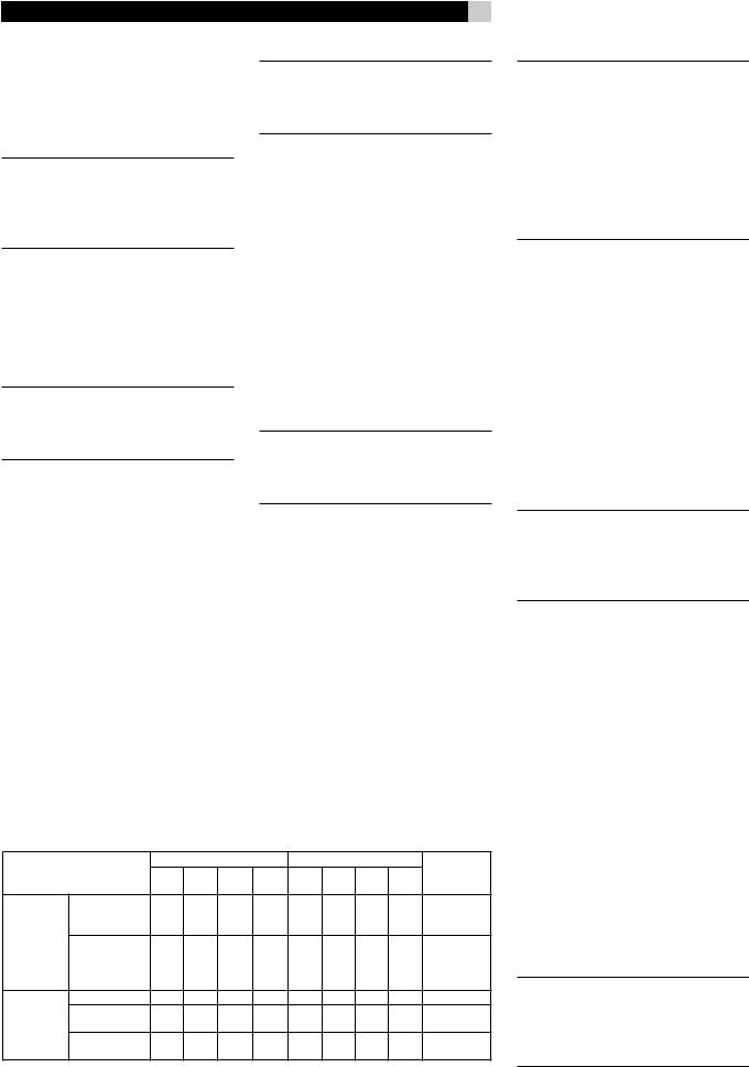
Video Input/Output formats
|
|
|
|
|||||||
|
|
|
● |
●* |
●* |
● |
● |
● |
● |
● |
|
|
|
|
|
|
|
|
|
||
|
● |
●* |
●* |
● |
● |
● |
● |
● |
||
|
|
|
● |
●* |
●* |
● |
● |
● |
● |
|
|
|
|
● |
●* |
●* |
● |
● |
● |
● |
|
|
|
|
● |
●* |
●* |
● |
● |
● |
● |
|
|
●* |
●* |
|
|
|
|
|
|||
|
|
|
● |
● |
● |
● |
● |
● |
||
|
|
|
● |
●* |
●* |
● |
● |
● |
● |
|
|
|
|
● |
●* |
●* |
● |
● |
● |
● |
|
|
|
|
● |
●* |
●* |
● |
● |
● |
● |
|
|
|
|
|
|
|
● |
|
|||
*
NOTE: When using a progressive scan or 1080i HDTV video signal from the Component Video inputs, the TV monitor cannot display the video signal and the OSD menus at the same time. When the main OSD setup menus are displayed, the progressive video signal is interrupted and restored when the OSD menus are cancelled. The temporary OSD information displays (such as volume setting, etc.) are not displayed.
VIDEO 1–4 HDMI Inputs 
HDMIinputsprovidevariousdigitalvideoconnections for use with components that have either HDMI outputs or DVI-D outputs (with an appropriate DVI-HDMI adapter). HDMI connections carry video signals in all formats including progressive scan up to 1080p. The implementation of HDMI supports audio signals, or a separate audio connection from an HDMI component.
Four inputs, labeled HDMI VIDEO IN 1–4 accept signals from source components.
NOTE: When using HDMI connections, the TV monitor can display the OSD menus and can also display video from Composite, S-Video, or Component Video sources, as the RSX-1058 is capable of upscaling these signals.
TV Monitor Outputs 


The TV MONITOR outputs of the RSX-1058 send the video signal to your TV monitor. Four types of video output connections are provided – RCA Composite video, S-Video, Component Video, and HDMI digital.
TheCompositeVideooutputsendsallinterlace video inputs to the TV monitor; the S-Video output also sends all interlace video inputs to theTV.TheHDMIoutputsendsallformatvideo inputs to the TV; the Component Video output also sends all format source inputs to the TV. Therefore, HDMI and Component Video are the most convenient type of connection. It is always possible to use Component or HDMI as a single output connection, because the RSX-1058 includes upconversion and scaling for all video inputs. See the VIDEO INPUT/ OUPUT FORMATS list, on this page.
NOTE: When you have changed the output resolution in the VIDEO/HDMI menu during operation, restart by switching power OFF and ON again, to stabilize the picture image in the new resolution setup.

19 |
English |
NOTE: HDTV Component Video output is subject to HDCP copy protection. It may not display 720p or 1080i resolution when the source signal incorporates copy protection. However, when Video Out is set to 480p/576p in the VIDEO/HDMI menu, all sources will be available.ComponentVideooutputisnotavailable for 480i/576i images.
NOTE: Do not connect HDMI and Component Video outputs to a monitor simultaneously, as the two video image signals may affect each other.
HDMI connections:
•The RSX-1058 uses the HDMI Ver. 1.1 standard. TV monitors with HDMI inputs should be compatible with this version.
•The video signal sent to the TV through the HDMI connection will not be displayed properly unless all HDMI components in the system, including the TV monitor, are compatible with the HDCP copy protection standard.
•Onlyaudiosignalspassed-throughdirectly from the source component are sent to the TV set through the HDMI connection. To send decoded audio from the RSX-1058 to the TV, you must select ‘TV mode’ in the VIDEO/HDMI menu.
•TV monitors with DVI-D connections can usually be connected to the HDMI output of the RSX-1058 with the use of an appropriate 24-pin DVI-HMDI adaptor. However, there are occasionally some incompatibilities with older DVI-D equipped monitors.
•Use the scaler setting of the RSX-1058 ‘VIDEO OUT FORMAT’ in the VIDEO/ HDMI menu to match the natiive resolution of the TV monitor.
•In general, HDMI is the optimum connection for digital high-definition monitors such as LCD, plasma, or DLP monitors.
NOTE: Do not connect HDMI and Component Video outputs to a monitor simultaneously, as the two video image signals may affect each other.
ZONE OUT Video Outputs 
TheZONEOUTVideooutputsoftheRSX-1058 send a Composite video signals to TV monitors in Zone 2, 3 & 4.
NOTE:OnlyCompositevideoinputsignalsare available at the Zone 2, 3 & 4 video outputs.
Digital Audio
Input & Outputs
The RSX-1058 provides digital connections which may be used in place of, or in addition to, the analog audio input and output connections described in the previous sections. These connections include seven digital inputs and also an HDMI Audio digital input. and two digital outputs (for recording),
These digital connections can be used with any source component that supplies a digital signal, such as a DVD player, CD player, or satellite TV tuner.
NOTE:Withadigitalconnection,theRSX-1058 will be used to decode the signal, rather than the source component’s internal decoders. In general, you must use digital connections for a DVD player or other component that supplies a Dolby Digital or DTS signal; otherwise the RSX-1058 will not decode these formats.
Digital Inputs 
The RSX-1058 accepts digital inputs from source components such as CD players, satellite TV tuners, and DVD players. The builtin digital processor senses and adjusts to the correct sampling rates.
There are seven digital inputs on the rear panel, three coaxial and four optical, as well as HDMI Audio input. These digital inputs can be assigned to any of the input sources using the INPUT SETUP screen during the setup process. For example, you can assign the COAXIAL 1 digital input connector to the VIDEO 1 source and the OPTICAL 2 digital input to the VIDEO 3 source. By default, the source input buttons are factory configured to select the following inputs:
CD: |
Digital Coaxial 2 |
Tuner: |
Analog (built-in) |
Tape: |
Digital Coaxial 3 |
Video 1: |
HDMI Audio (HDMI 1) |
Video 2: |
HDMI Audio (HDMI 2) |
Video 3: |
Digital Optical 1 |
Video 4: |
Digital Optical 2 |
Video 5: |
Digital Coaxial 1 |
NOTE: When using digital connections, you should also make the analog audio input connections described previously. The analog connection is necessary to record to an analog recorder in some circumstances or for ZONE 2, 3 & 4 operation.
Digital Outputs 
The RSX-1058 has two digital outputs (one coaxial and one optical) to send the digital signal from any of the digital inputs to a digital recorder or outboard digital processor. When a digital input source signal is selected for listening, that signal is automatically sent to both digital outputs for recording.
NOTE: Only digital signals from source components are available at these outputs. Analog signals cannot be converted and are not available at the digital outputs.
Other Connections
AC Input 
Your RSX-1058 is configured at the factory for the proper AC line voltage in the country whereyoupurchasedit(USA:120volts/60Hz AC or CE: 230 volts /50 Hz AC ). The AC line configuration is noted on a decal on the back of your unit.
Plug the supplied cord into the AC INPUT receptacle on the back of the unit.
NOTE: Memorized settings and video labels are preserved indefinitely, even if the RSX-1058 is disconnected from AC power.
Master Power Switch 
The large rocker switch on the rear panel is a master power switch. When it is in the OFF position, power to the unit is completely off. When it is in the ON position, the front-panel STANDBY and remote control ON/OFF buttons can be used to activate the unit or put it into standby mode.
NOTE: After all connections are completed, the rear panel master power switch should be put in the ON position and usually left in that position.

RSX-1058 Surround Sound Receiver
12V TRIGGER Connections 
Many Rotel amplifiers offer the option of turning them on and off using assignable 12 volt trigger signals. These six connections provide this 12 volt trigger signal from the RSX-1058. When the RSX-1058 is activated, a 12 volt DC signal is sent to the amplifiers to turn them on. When the RSX-1058 is put in STANDBY mode, the trigger signal is interrupted and the amplifiers turn off.
NOTE: The 12V Trigger outputs can be assigned to turn on only when specific input sources are activated. See the Input Setup and Zone 2–4 Setup menus in the Setup section of this manual for details.
To use the remote turn on feature, connect one of the RSX-1058’s 12V TRIG OUT jacks which is assigned to the 12 volt trigger input of a Rotel amplifier, using a cable with mono 3.5 mm mini-plugs on both ends. The +12 V DC signal appears at the “tip” connector.
REM IN Jacks 
Four 3.5 mm mini-jacks (labeled ZONE 2, 3 & 4, and EXT) receive command codes from an industry-standard infrared receiver (Xantech, etc.), used when the IR signals from a hand held remote control cannot reach the front-panel IR sensor or zone rooms.
EXT: The EXT jack is used with an outboard IR receiver to duplicate the front-panel IR sensor. This feature is useful when the unit is installed in a cabinet and the front-panel sensor is blocked or when IR signals need to be relayed to other components.
ZONE: The ZONE jacks are used with IR repeater systems to receive signals from IR control systems in remote locations. For example, remote signals sent to the ZONE 2 REM IN control the ZONE 2 features of the RSX-1058 and can be relayed to other components.
Consult your authorized Rotel dealer for information on external receivers and the proper wiring of 3.5 mm mini-plugs to fit the REM IN jacks.
NOTE: The IR signals from the EXT REMOTE IN and ZONE 2–4 REMOTE IN jacks can be relayed to source components using external IR emitters or hard-wired connections from the IR OUT jacks. See the following section for additional information.
20
IR OUT Jacks 
The IR OUT 1 & 2 jacks send IR signals received at the ZONE 2–4 REM IN or the EXT REM IN jacks to an infrared blaster or emitter placed in front of a source component’s IR sensor. In addition, the IR OUT can be hardwired to Rotel CD players, DVD players, or tuners with a compatible connector.
These outputs are used to allow IR signals from Zones 2–4 to be sent to the source components, or to pass along IR signals from a remote in the main room when the sensors on the source components are blocked by installation in a cabinet.
See your authorized Rotel dealer for information on IR emitters and repeater systems.
Computer I/O 
The RSX-1058 can be operated from a computer with audio system control software from third-party developers. This control is accomplished by sending operating codes from the computer via a hard-wired RS-232 serial connection. In addition, the RSX-1058 can be updated using special software from Rotel.
The COMPUTER I/O input provides the necessary network connections on the rear panel. It accepts standard RJ-45 8-pin modular plugs, such as those commonly used in 10BaseT UTP Ethernet cabling.
For additional information on the connections, cabling, software, and operating codes for computercontrolorupdatingoftheRSX-1058, contact your authorized Rotel dealer.
Making Connections
CD Player 

See Figure 10
Connect the left and right analog outputs from the CD player to the AUDIO IN jacks labeled CD (left and right).
Optional: Connect the digital output of the CD player to any of the Optical or Coax digital inputs on the RSX-1058. Use the INPUT SETUP screen to assign that digital input to the CD source. The default assignment is COAXIAL 2.
There are no default video connections for a CD Player.
DVD Player 


See Figure 6
Standard Definition TVs:
In a system with a standard definition TV, DVD connections can be made to the VIDEO 1, 2, 3, 4 or 5 inputs. You may wish to use assigned Video Inputs with interlace picture for DVD players. The video picture is then available by the assigned Video Inputs. The analog audio is the same as the input labelled terminals.
The video setting in each video source is by assignment, so the INPUT labels of VIDEO 1-5 do not relate to video terminal numbers.
It is possible to assign any type of video terminals, from the available three Composite Video, three S-Video, three Component Video and four HDMI.
If the monitor used is SDTV, an interlace source (480i/576i) should be used.
NOTE: If you plan to distribute video from the DVD player to a TV monitor in Zone 2, 3 or 4, you must make a composite video connection.
High Definition TVs:
It is possible to connect any video input for use with an HDTV monitor, as the RSX-1058 has a built-in video converter and scaler inside. However, the higher the resolution of the input signal, the higher the quality of the picture.
If you intend to use the progressive scan feature with an HDTV monitor, you should use Component Video and/or HDMI video connections from the DVD player. If the DVD player has a DVI-D output, this can usually be connected to the HDMI input on the RSX-1058 using a DVI-HDMI adapter.
Connect a set of Component Video cables or an HDMI cable from the DVD player to the appropriate VIDEO 1, 2 or 3 input or HDMI 1–4 input on the RSX-1058.
Digital Audio connections:
Connect the digital output of the DVD player to any one of the OPTICAL IN or COAXIAL IN digital inputs on the RSX-1058. Use the INPUT SETUP screen to assign that digital input to
the same video input source used above. If an HDMI connection is used, assign HDMI Audio for the digital audio, or one of the OPTICAL IN or COAXIAL IN digital inputs.
Analog audio connections:
If you want to record the audio signal from the DVD player or distribute the audio signal to Zones 2–4, connect the left and right analog outputs from the DVD player to the left and right AUDIO IN jacks corresponding to the VIDEO IN input selected above.
Cable, Satellite, HDTV Tuner
See Figure 8
Standard Definition TVs:
In a system with a standard definition TV, cable or satellite tuner connections can be made to the VIDEO 1, 2, 3, 4, or 5 inputs. You may wish to use assigned Video Inputs with interlace picture. The video picture is then available by the assigned Video Input. The analog audio is the same as the input labelled terminals.
The video setting in each video source is by assignment, so the INPUT labels of VIDEO 1-5 do not relate to video terminal numbers.
It is possible to assign any type of video terminals, from the available three Composite Video, three S-Video, three Component Video and four HDMI.
If the monitor used is SDTV, an interlace source (480i/576i) should be used.
NOTE: If you plan to distribute video from the tuner to a TV monitor in Zone 2, 3 or 4, you must make a composite video connection.
High Definition TVs:
It is possible to connect any video input for use with an HDTV monitor, as the RSX-1058 has a built-in video converter and scaler inside. However, the higher the resolution of the input signal, the higher the quality of the picture.
With a high-definition cable or satellite tuner and an HDTV monitor, you should use Component Video and/or HDMI video connections from the tuner. If the tuner has a DVI-D output, this can usually be connected to the HDMI input on the RSX-1058 using a DVIHDMI adapter.
21 |
English |
Connect a set of Component Video cables or an HDMI cable from the tuner to the appropriate input on the RSX-1058.
Digital Audio connections:
Connect the digital output of the tuner to any one of the OPTICAL IN, COAXIAL IN or HDMI IN digital inputs on the RSX-1058. Use the INPUT SETUP screen to assign that digital input to the same video input source used above. For example, if you use the Video 4 inputs above, assign the digital input to the HDMI IN 1 input.
Analog audio connections:
If you want to record the audio signal from the tuner to a VCR or distribute the audio signal to Zones 2–4, connect the left and right analog outputs from the DVD player to the left and right AUDIO IN jacks corresponding to the VIDEO IN input selected above.
Audio Recorder 


See Figure 11
Connect the left and right analog outputs from an audio tape deck to the AUDIO IN jacks labeled TAPE IN (left and right).
Connecttheleft/rightAUDIOOUT/TAPEOUT jacks to the inputs on the audio tape deck.
Optional: For a digital recording device, connect the digital output of the recorder to one of the OPTICAL IN or COAXIAL IN digital inputs on the RSX-1058. Use the INPUT SETUP screen to assign that digital input to the TAPE source. If the recording device accepts a digital recording input, connect either the OPTICAL OUT or COAXIAL OUT connection to the digital input of the recorder.
No video connections are required for an audio recording device.
VCR or Digital Video Recorder
See Figure 9
VCR connections can be made to the VIDEO 1, VIDEO 2, or VIDEO 3 inputs and outputs. If you choose VIDEO 1, make sure that you use either Composite or S-Video inputs and outputs for all analog audio and video connections.
Connect video cables (Composite Video, S-Video, and/or Component Video) from the output of the VCR to the appropriate video input which is assigned.
Connect video cables (Composite Video and/or S-Video) from the VIDEO OUT jacks to the VCR inputs.
Connect the left and right analog outputs from the VCR to one pair of the AUDIO IN jacks labeled VIDEO 1–3.
Connect the left and right AUDIO OUT jacks for VIDEO 1–2 to the analog inputs on the VCR.
Optional: For a digital recording device, you can use digital audio connections. Connect the digital output of the recorder to one of the OPTICAL IN or COAXIAL IN digital inputs on the RSX-1058. Use the INPUT SETUP screen to assign that digital input to the VIDEO source (VIDEO 1, 2, or 3) used for the previous connections. If the recording device accepts a digital recording input, connect one of the OPTICAL OUT or COAXIAL OUT connections to the digital input of the recorder.
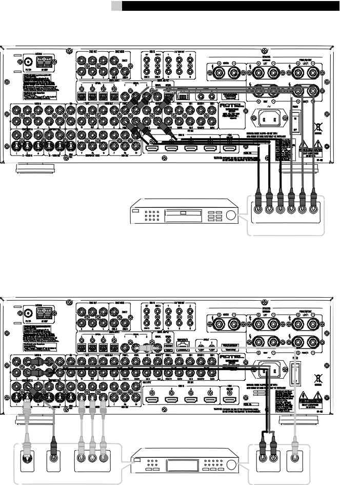
DVD-A or SACD Player 
See Figure 7
To hook up a DVD-A, a SACD player, or any external surround decoder, use audio RCA cables to connect the outputs of the player to the RCA jacks labeled MULTI INPUT, making sure that you observe proper channel consistency, i.e. connect the right front channel to the R FRONT input, etc. Depending on your system configuration, make six connections (FRONT L & R, SURROUND L & R, CENTER, and SUBWOOFER), seven connections (adding a CENTER BACK connection), or eight connections (adding two CENTER BACK connections).
The MULTI inputs are analog bypass inputs, passing signals directly through to the Volume Control and preamp outputs, bypassing all of the digital processing. The RSX-1058 provides an optional bass redirect feature that duplicates the seven main channels and passes them through an analog 100 Hz low pass filter, creating a summed mono subwoofer output derived from the main channels. See the INPUT SETUP menu in the Setup section of this manual for details on bass redirect feature.

RSX-1058 Surround Sound Receiver
TV Monitor 


See Figure 5
Connect the TV MONITOR output to the corresponding input on your television monitor, using Composite Video, S-Video, Component Video, and/or HDMI cables.
NOTE: The RSX-1058 can send any video input of interlaced format for output to Composite or S-Video monitor connections. Please see the VIDEO INPUT/OUPUT FORMATS list, in the “Video Inputs & Outputs” section of this manual. The RSX-1058 automatically handles PAL or NTSC video formats, so if a PAL source is connected to the input, it will provide PAL output; if the source is NTSC, the video output will be NTSC.
For HDTV monitors:
To send progressive scanned or high-defi- nition signals to the TV, you must connect it with either a set of three Component Video cables or an HDMI digital cable. Either can provide excellent results, but in general using the HDMI cable is preferable for a monitor that displays digital signals (LCD, plasma, DLP, etc.). Component Video cables would be preferable for CRT-based direct view or rear projection monitors that display analog signals.
If you use the HDMI connection, the monitor will display video at whatever resolution is sent from the source component. Set the resolution of the source component to match the TV’s native resolution.
NOTE: Do not connect HDMI and Component Video outputs to a monitor simultaneously, as the two video image signals may affect each other.
The RSX-1058 HDMI connections conform to the Version 1.1 standard.
You can usually connect the HDMI output of theRSX-1058toamonitorwithDVI-Dinputsby using an appropriate HDMI-DVI adapter.
NOTE: In order for HDMI signals to be displayed properly, the TV monitor must be compatible with HDCP copy protection.
Speakers 
See Figure 3
The RSX-1058 has built-in amplifiers to power up to five speakers. There are five pairs of binding post connections (one pair for each
22
speaker) which accept bare wire, spade lugs, or banana plug connectors (in some markets).
NOTE: Speakers should have an impedance of 8 ohms or higher.
Each pair of connectors is color-coded for polarity: red for positive and black for negative. All speakers and all speaker wire is also marked for polarity. For proper performance, you must maintain this polarity at all speaker connections. Always connect the positive terminal of each speaker to the corresponding red speaker terminal on the RSX-1058 and the negative speaker terminal to the corresponding black connector on the RSX-1058.
There are connectors for FRONT LEFT, FRONT RIGHT,SURROUNDLEFT,SURROUNDRIGHT, and CENTER. You must connect each of the five speakers to the proper terminal on the RSX-1058.
Route the wires from the RSX-1058 to the speakers. Leave enough slack so you can move the components to allow access to the speaker connectors. If you are using banana plugs, connect them to the wires and then plug into the backs of the binding posts. The collars of the binding posts should be screwed in all the way (clockwise). If you are using terminal lugs, connect them to the wires. If you are attaching bare wires directly to the binding posts, separate the wire conductors and strip back the insulation from the end of each conductor. Be careful not to cut into the wire strands. Unscrew the binding post collars. Place the connector lug or the twisted bare wire around the binding post shaft. Turn the collars clockwise to clamp the connector lug or wire firmly in place.
1.Connect the front right speaker to the binding posts labeled FRONT/CB/ZONE RIGHT/2.
2.Connect the front left speaker to the binding posts labeled FRONT/CB/ZONE LEFT/1.
3.Connect the center channel speaker to binding posts labeled CENTER.
4.Connectthesurroundrightspeakertobinding posts labeled SURROUND RIGHT.
5.Connect the surround left speaker to binding posts labeled SURROUND LEFT.
NOTE: Be sure that no loose wire strands can touch adjacent wires or connectors. After you have connected the speakers, you need to configure the RSX-1058 for the size and style of speakers in your system and calibrate the relative volume levels of the speakers using the built-in test tones. See the Setup section of this manual.
Redirect Feature
The RSX-1058 has a “redirect” feature that allows you to use the front left and front right amplifierchannelstopowereithercenterback or Zone speakers. For example, you might use a separate Rotel stereo power amplifier to drive the front speakers and then use the extra amplifier channels in the RSX-1058 to power two center back speakers.
If your system does not have center back speakers, you can also redirect the built-in front channel amplifiers to drive a pair of speakers in Zone 2, 3 or 4 .
Tousetheredirectfeaturetopowercenterback speakers in a 6.1 or 7.1 channel system:
1.Connect the center back speaker in a 6.1 channel system or the center back left speaker in a 7.1 channel system to the binding posts labeled FRONT/CB/ ZONE LEFT/1.
2.Connect the center back right speaker to binding posts labeled FRONT/CB/ZONE RIGHT/2.
3.Go to the DEFAULT SETUP screen of the ON-SCREEN MENU system and change the REDIRECT setting to the center back channels instead of the front channels, and set FACTORY DEFAULT to ‘YES’.
Connecting a Subwoofer 
See Figure 3
To hook up a powered subwoofer, connect a standard RCA audio cable from either of the two PREOUT jacks labeled SUB to the input on the subwoofer’s power amp. Both SUB outputs provide the same signal. Use either connection for a single subwoofer. Use both connections to hook up two subwoofers.
After you have connected the subwoofer, you need to configure the RSX-1058 to use the subwoofer and calibrate the relative volume level of the subwoofer using the built-in test tones. See the Setup section of this manual.

Amplifiers 
To hook up power amplifiers, connect an audio cable from each PREOUT jack to the input of the amplifier channel that will power the corresponding speaker. In a full home theater system, you will need to make as many as seven different connections in addition to the subwoofer. These connections are labeled FRONT L &R, CENTER, and REAR L & R. There are two CENTER jacks, use either jack for a single center channel or both if you have two center channels. In six or seven channel systems, you will make one or two additional connections for center back speaker(s). These jacks are labeled CB1 and CB2. Use CB1 for a single center back channel.
Make sure that you have each output connected to the correct amplifier channel (front right, left rear, etc.).
AM Antenna 
See Figure 12
The RSX-1058 includes a plastic loop antenna to receive AM radio signals. Remove this antenna from the box and locate it near the RSX-1058. It can be tacked to a wall, using the mounting tab provided. Alternatively, you can fold the center portion of the antenna to form a tabletop stand.
Connect the 300 ohm twin-conductor wire from the loop antenna to the push terminals labeled AM LOOP, attaching one wire to each terminal. It does not matter which wire attaches to which terminal, but make sure that the connections are solid and that the two wires do not touch.
You may need to rotate or otherwise reorient the antenna to find the best position.
NOTE: To use an outdoor antenna, connect its 300 ohm twin-conductor wire to the terminals in place of the loop antenna.
FM Antenna 
See Figure 12
The RSX-1058 is supplied with a T-shaped in- doorFMantenna.ConnectthecoaxF-typeplug to the FM antenna connector on the RSX-1058. For best reception, unfold the T-shaped antenna. Eyelets at both ends of the T allow tacking the antenna to a wall, if desired. Experiment with positioning for best reception.
23
NOTE: To use an outdoor antenna, connect its 75 ohm coax lead wire to the FM connector instead of the indoor wire antenna, only after a professional contractor has installed the antenna system in accordance with local electrical codes.
English
OPERATING THE
RSX-1058
Considering its large number of features, settings, and options, the RSX-1058 is remarkably easy to operate. The key to operating the RSX-1058 is its system of On-Screen Displays (OSD) which guide you through various choices.
The RSX-1058 can be operated from the front panel or the remote control. Front-panel controls are unusually simple to use, with just a few knobs and buttons to guide you through OSD menu options. The remote control provides more complete control options.
To guide you through the operation of the RSX-1058,thissectionofthemanualstartswith explaining the basic layout and function of the front panel and the remote control. Then, we explain the basic operations such as turning the unit on and off, adjusting volume, selecting a source for listening, etc. Following that is a detailed explanation of surround sound modes and how to configure the RSX-1058 for various types of recordings. Finally, there are instructions for additional features and Zones operation. All of these are features that may be used in normal use. The last section of the manual (Configuration) details options that may be selected during initial setup and configuration of the unit, many of which will be set once and left untouched.
Throughoutthismanual,numbersingrayboxes refer to the RSX-1058 illustration at the front of this manual. Letters refer to the RR-1060 remote illustration. When both appear, the function is found on both the RSX-1058 and the remote. When only one appears, that function is found only on the RSX-1058 or the remote.
Front Panel Overview
The following is a brief overview of the control and features on the front panel of the RSX-1058. Details concerning the use of these controls are provided in subsequent sections of this manual describing various tasks.

RSX-1058 Surround Sound Receiver
Front-panel Display 
The fluorescent (FL) display in the upper portion of the RSX-1058 provides information about the status of the unit, tuner reception, and activation of special features. The main portion of the display typically shows the current input source (or radio station frequency) selected for listening on the left side and the current volume level on the right.
Icons along the left side of the display show the currently selected digital input. Icons at the right of the display show individual surround channels and are used in configuring the system. Icons across the bottom of the display show the current surround mode and other special features. Icons at the top of display assist in tuning radio stations and operation of RDS/RBDS features.
TheFLdisplaycanbeturnedoff,ifdesired.See the MENU button section for instructions.
Remote Sensor 
This sensor receives IR signals from the remote control. Do not block this sensor.
NOTE: The remainder of the buttons and controls on the front panel are described in the Overview of Buttons and Controls section.
Remote Control Overview
The RSX-1058 includes a full-function learning remote control that can operate the RSX-1058 plus nine other audio/video components.
A separate manual gives detailed instructions on programming and using the RR-1060 to replace all of the remote controls in your system. The RR-1060 manual covers many extra features (such as custom labeling of remote buttons that appear in its LCD display). To avoid duplication, we provide only basic information about using the RR-1060 to operate the RSX-1058 in this manual.
Many of the RR-1060 functions duplicate the front-panel controls. For that reason, we cover the controls on the remote under appropriate topics throughout this manual. Letters in gray boxes next to the name of a function refers to the labeled illustration of the remote at the front of this manual.
24
Using the RR-1060
AUDIO Button 
To operate the RSX-1058 with the remote, make sure that the AUDIO mode is active by pressing the AUD button on the remote before you start. If one of the other buttons (CD, TAPE, etc.) is pressed, the remote will control another component, not the RSX-1058. The AUDIO mode will stay active until another DEVICE/INPUT button is pressed.
Overview of Buttons
and Controls
This section provides a basic overview of the buttons and controls on the front panel and the remote control. Detailed instructions on the use of these buttons are provided in the more complete operating instructions in the following sections. Buttons or controls identified with a number appear on the front panel. Those identified with a letter appear on the remote control. When both a number and a letter appear, the control is duplicated on both the front panel and the remote control.
STANDBY Button 
POWER Button 
The front-panel STANDBY button and the remote control POWER button activate or deactivate the unit. The rear panel master POWER switch must be in the ON position for the remote standby function to operate.
ON/OFF Buttons 
ThepowerONandOFFbuttonsontheremote provide discrete ON and OFF commands to activate the unit or put it in standby mode. The rear panel master POWER switch must be in the ON position for the remote standby function to operate.
All OFF command: A long press of the OFF button (more than 3 seconds) sets all rooms to standby, from any room.
VOLUME Knob 
VOLUME Button 
The large rocker button on the remote and the large rotary control on the front panel provide the master VOLUME control, adjusting the output level of all channels simultaneously.
MUTE Buttons 

Push the MUTE button once to turn the sound off. An indication appears in the front panel andon-screen displays.Pressthe button again to restore previous volume levels.
NOTE: Pressing the volume buttons on the remote also cancels the muting function.
LIGHT Button 
Press this button on the side of the remote to turn the backlighting on for using the remote in a dark room.
DEVICE/INPUT Buttons 


The top row of buttons on the front panel plus the MULTI INPUT button are used to select source inputs for listening/viewing.
These buttons are duplicated on the remote, except that the MULTI INPUT button is labeled EXT and the remote buttons have two functions:
Short press: A short press of any button changes the device that the remote operates, but does not change the RSX-1058’s input selection.
Long press: A longer press changes the remote control device and changes the source input for listening/viewing in the main room.
NOTE:A longpressofthe EXT buttonchanges the input to the 7.1 channel analog MULTI INPUT. Pressing the AUD button only changes the remote device; there is no input source associated with this button.
D-SLT Button 
Press this button to change the digital input associated with the current source input.

SEL Button 
REC Button 
Press the front-panel SEL button or the remote control REC button to select the desired zone for additional changes such as changing the input, adjusting the volume, or turning a remote zone on or off. Repeatedly press the button until the desired zone appears in the front panel: RECORD > ZONE 2 > ZONE 3 > ZONE 4. Once the desired zone appears, you have 10 seconds to make the desired change. Change the input selection by pressing an INPUT button. When ZONES 2–4 appear, you can also adjust the volume, or turn the zone on or off by pressing the ZONE button.
A long press of the SEL or REC button is used tocancelthePARTYmodeandreturnallzones to their last previously selected inputs.
ZONE Button 

Either of these buttons serve as a standby button for the currently-selected remote zone, toggling the zone on or off. Select the desired zone using the front-panel SEL or remote control REC button as described above.
UP/DOWN Buttons 
These two buttons on the remote are used to move the cursor up or down to select lines in the OSD menus. These buttons are also used in conjunction with the TONE button to make CONTOUR/TONE adjustments.
+/– Buttons 
These two buttons on the remote are used to change settings on a selected line in the OSD menus. Also used for selecting options in some surround modes.
Speaker Selection Buttons 
These three buttons on the remote are used to select a speaker or group of speakers for temporary level adjustments. In addition, the C button is used in conjunction with the UP/ DOWN buttons for temporary adjustment of group delay/lip synch.
EQ Button 
This button on the remote is used to turn on and off the Cinema EQ feature, a high-cut filter useful for older movie soundtracks.
25
TONE Button 
This button on the remote is used for temporary Contour adjustments. It toggles between high frequency (HF) and low frequency (LF) modes. Once a mode is selected, the UP/ DOWN buttons are used to make the adjustments to the speaker or speakers selected in the Contour Setup menu.
NOTE:Permanentcontouradjustmentscanbe made using the Contour Setup menu.
Surround Mode Buttons 

Five buttons on the remote (2CH, PLC, PLM, 5CH, 7CH) and four buttons on the front panel (2CH, DOLBY PLIIx Mode, DTS/Neo 6, DSP) allow direct selection of certain surround modes. The function of these buttons varies depending on the type of recording being played. See the Manually Selecting Surround Modes section for detailed information.
SUR+ Button 
This button on the remote is used in conjunction with the +/– buttons for manual selection of surround modes and features. See the
Manually Selecting Surround Modes section for information.
DYN Button 
Used the DYN button on the remote to select the dynamic range control setting in Dolby Digital surround mode.
MENU/OSD Button 
Push this button on the remote to turn on the OSD menu system. If the menu system is already visible, push this button to cancel the display. Press and hold the button to turn off the front-panel display.
ENTER Button 
The ENTER button is used to confirm and memorize various settings in the setup and operation of the RSX-1058. Its use is described in detail in the relevant sections.
BAND Buttons 

Press either of the BAND buttons to toggle between AM and FM reception.
English
TUNING Buttons 

TheTUNINGbuttons(labeledCHUP/DOWN on the remote control) provide three different tuning functions, depending on the mode of operation: frequency tuning, preset tuning, or selection of an RDS/RBDS program type.
MEM Button 

The front-panel MEMORY button or remote control MEM button (also labeled “X”) is used with the NUMERIC buttons to store station presets.
NUMERIC Buttons 

The NUMERIC buttons on the front panel or the remote are used to enter the number of a memorized station preset or for direct entry of a station frequency.
DIRECT Button  FRQ DIRECT Button
The front-panel DIRECT and remote control FRQ DIRECT buttons are used in conjunction with the NUMERIC buttons for direct entry of a station frequency in AM/FM tuning.
MONO Button  FM MONO Button
The front-panel MONO and remote control FMMONObuttonschangetheFMmodefrom stereo reception to mono reception.
TUNE Button 
PRESET Button 
P-TUN Button 
The TUNE, PRESET, and P-TUN buttons on the remote are used to select FREQUENCY tuning or PRESET tuning modes. The TUNE and PRESET buttons select the modes directly. The P-TUN button toggles between the two modes.
SCAN Button 
Presetscantuningautomaticallyscansthrough the memorized station presets, playing each for 5 seconds. Press the SCAN button on the remote to begin preset scanning. Press the button again to stop the scanning and listen to the desired preset.
RSX-1058 Surround Sound Receiver
RDS/RBDS Buttons 
Four remote control buttons (DISP, PTY, TP, TA) are used to activate various RDS/RBDS tuning features. See the RDB/RBDS Tuning section of the manual for detailed information.
Basic Operations
This section covers the basic operating controls of the RSX-1058 and the remote.
Power and Standby On/Off
TherearpanelPOWERswitchontheRSX-1058 is a master power switch. The button must be in the ON position for the unit to operate. When it is in the OFF position, the unit is fully off and cannot be activated from the front panel or remote control.
In normal operation, the rear panel POWER switch is always left in the ON position. The RSX-1058 is activated and deactivated using the front-panel STANDBY button, the remote control POWER button, or the remote ON/ OFF buttons. When activated, the RSX-1058 is fully functional and the front-panel display illuminated. When deactivated, the unit goes into a standby mode, with minimal power applied to the microprocessor.
NOTE: When the unit has AC power applied and the rear panel POWER switch is on, the front-panel STANDBY LED lights, regardless of whether the unit is in standby mode or activated.
The front-panel STANDBY button and the remote control POWER button function as toggle switches. Press either button to activate the unit. Press either button again to put the unit in standby mode.
The ON/OFF buttons on the remote serve the same function, but provide discrete ON (active) or OFF (standby) commands.
NOTE: When using the Zone room capability of the RSX-1058, the standby activation is completelyindependentforthemainroomand the zones. ON/OFF commands sent from the remote in the main room will not affect Zones 2–4.PressingtheON/OFFbuttonsonaremote located in Zone 2, 3 or 4 will only affect that zone and not the main room. When the unit is activated in one of the zones, that zone’s icon is lit in the front-panel FL display.
26
There are four available power mode options, which may be useful in configuring the RSX-1058 for special system configurations. See the Other Options menu in the Setup section of this manual for additional details on changing the default standby behavior.
‘Resume’ retains the last power configuration when the main power is switched OFF and then switched ON again. For example, if the RSX-1058 is in operation and the main power is switched OFF, when the main power is switched ON, the unit will be in operation mode again.
All OFF command: A long press of the OFF button (more than 3 seconds), from any room, sets the RSX-1058 to standby.
Volume Adjustments 

ThelisteningvolumeoftheRSX-1058canbead- justed from the front panel or the remote.
Front Panel: Rotate the front-panel VOLUME knob clockwise to increase the volume, counterclockwise to decrease.
Remote: Press the VOL UP button to increase the volume; press the VOL DOWN button to decrease.
When you adjust the volume, the setting is shown on the SDTV monitor and/or the front-panel display. The current volume setting is also shown on the SYSTEM STATUS OSD screen.
NOTE: The VOLUME controls can be used to change the volume in Zone 2, 3 or 4. Press the front-panel or remote control ZONE button and adjust the volume. After 10 seconds, the VOLUME control reverts to normal operation.
Muting the Sound 

The volume of the RSX-1058 can be turned off or muted. Push the MUTE button on the front panel or the remote once to turn the sound off. A MUTE indication appears in the OSD and the front-panel displays. Press the MUTE button again or adjust the volume settings to restore output levels.
Selecting Inputs
Input Buttons 


You can select any of nine source inputs for listening and/or watching: CD, TUNER, TAPE, VIDEO 1, VIDEO 2, VIDEO 3, VIDEO 4, VIDEO 5, or MULTI INPUT (EXT on remote).
The front-panel display and the ON-SCREEN DISPLAY show the name of the current listening source selection. The labels for VIDEO sources can be customized to match your components.
NOTE: When the TUNER input source button is pressed, the frequency of the currently tuned station is displayed. Pressing the button again toggles the display to show the word TUNER instead of the frequency display.
All of the source inputs can be customized using the ON-SCREEN DISPLAY configuration menus to accept either analog signals or digital signals from one of the seven assignable digital inputs, or HDMI Audio. When a digital input is assigned, the RSX-1058 checks for the presence of a digital signal at that input. If a digital signal is present when the source is selected, it is automatically activated and the proper surround mode enabled. If no digital signal is present, the analog inputs for that source are selected. This auto-sens- ing is the preferred configuration for digital source inputs such as DVD players. When an ANALOG input is assigned, the unit will not access a digital signal, even though one may be available at the digital input.
By default, the source input buttons are factory configured to select the following inputs:
CD: |
Digital Coaxial 2 |
Tuner: |
Analog (built-in) |
Tape: |
Digital Coaxial 3 |
Video 1: |
HDMI Audio (HDMI 1) |
Video 2: |
HDMI Audio (HDMI 2) |
Video 3: |
Digital Optical 1 |
Video 4: |
Digital Optical 2 |
Video 5: |
Digital Coaxial 1 |

Each source input should be configured using the ON-SCREEN DISPLAY menu system to use the desired input type (analog or digital auto-sensing). See the INPUT MENU section for configuration instructions.
NOTE:Inadditiontoselectinganalogordigital signals, the configuration options also permit custom labeling and selection of a default surround mode for each of the eight inputs.
The input source buttons can also be used (with the SEL button described in the next section) to select an analog input source signal to be available at the outputs for recording, and to select an analog input source for Zones 2–4.
Selecting a Source Input from the Front Panel 


To select a source for LISTENING: Press one of the eight INPUT buttons or the MULTI INPUT button.
ToselectasourceforRECORDING:Press the SEL button once and then press one of the eight INPUT buttons within 5 seconds.
To select a source for Zone 2, 3 or 4:
Press the SEL button two or more times to select the desired zone and then press one of the INPUT buttons within 10 seconds.
NOTE: See the section on Zone 2–4 operations for details of selecting a source for the remote zone.
Selecting a Source from the Remote 


To select a source for LISTENING in the main room: press and hold one of the DEVICE/INPUT buttons for more than one second. To select the MULTI INPUT, press and hold the EXT button.
NOTE: A short press of a DEVICE/INPUT button changes the remote control device only, but does not change the source input.
To select a source for RECORDING:
Press the REC button. Then, press and hold one of the DEVICE/INPUT buttons within 5 seconds.
Alternatively, you can press the REC button and then use the +/– buttons to scroll through the available source options. Select any input (CD, TUNER, TAPE, or VIDEO 1–5). Selecting the SOURCE option links the recording
27
source to the input selected for main room listening. Whatever input is selected for listening is also sent to the record outputs.
To select a source for Zone 2, 3 or 4:
Press the REC button two or more times to select a zone. Then, press and hold one of the DEVICE/INPUT buttons within 10 seconds.
Alternatively, you can press the ZONE button and then use the +/– buttons to scroll through the available source options. Select any input (CD, TUNER, TAPE, or VIDEO 1–5). Selecting the SOURCE option links the Zone 2, 3 or 4 source to the input selected for main room listening. Whatever input is selected for the main room is also sent to the Zone 2, 3 or 4 outputs.
Selecting the Same Input for all Outputs 


You may wish to have the same input for listening, recording, and all of the remote zones. The RX-1058 makes this configuration (called Party Mode) easy by linking the inputs for recording and remote zones to the input selected for listening. When linked, changing the input selection for listening will automatically change the input for recording and remote zones.
To activate Party Mode, press and hold the ZONE button on the front panel or Remote for at least 3 seconds. The words PARTY ON appear briefly in the display and the ZONE icon flashes for ten seconds. The record input selection and all remote zone input selections will be displayed as “SOURCE”, indicating that they are linked to the input selected for listening. While in PARTY mode, a “P” indicator remains in the front-panel display.
To cancel Party Mode, press and hold the SEL button on the front panel or the REC button on the remote for at least 3 seconds. Party Mode is cancelled as indicated by the temporary display of the words PARTY OFF in the front-panel display. The recording input and the inputs for all remote zones revert to their last previous selection, no longer linked to the listening input.
You can also cancel the link for just the record output or for one individual zone by selecting a different input for that output. In this case, the input selection for the unchanged record output or remote zones remained linked to the listening input selection. Any source change cancels the “P” indicator in the display.
English
Selecting Digital Inputs 
A default digital audio input can be specified for each source input using the Input Setup menu. However, you can override the default digital input for the currently selected source by pressing the D-SLT button on the remote. Each press of the button steps to the next digital input in order: OPTICAL 1, OPTICAL 2, OPTICAL 3, OPTICAL 4, COAXIAL 1, COAXIAL 2, COAXIAL 3. The actual choices you see will be limited to those inputs with an active digital signal connected, so you may not see all of the inputs listed.
Overview of
Surround Formats
To get the best performance from your RSX-1058, it helps to understand the many surround sound formats available today, to know which decoding process to use for a particular recording, and how to select it. This section provides basic background information about surround sound formats. The following sections provide detailed operating instructions for automatic and manual selection of surround modes.
NOTE: The RSX-1058 has built-in amplifiers to drive five speakers in a 5.1 channel system. To use surround modes for 6.1 or 7.1 channel systems, you will need a separate power amplifier to drive one or two speakers.
Dolby Surround
Dolby Pro Logic II
The most widely available surround sound format for consumer audio/video is Dolby Surround®, available on nearly all commercial VHS tapes, many television broadcasts, and most DVDs. Dolby Surround is the consumer version of the analog Dolby Stereo system first introduced in the film industry in 1972. It is a matrix-encoding system that records front left, front center, front right, and a mono surround channel into a 2-channel stereo recording. During playback, a Dolby Pro Logic® or Pro Logic II decoder extracts each channel and distributes it to the appropriate speakers.
TheoriginalDolbyProLogicdecoderdelivered a mono signal with reduced high-frequency content to the surround speakers. A more advanced decoder in the RSX-1058, Dolby

RSX-1058 Surround Sound Receiver |
28 |
Pro Logic II, increases the separation and frequency response of the surround channels for significantly improved performance with Dolby Surround encoded recordings.
Dolby Pro Logic II decoding should be used for any analog recording labeled “Dolby Surround” or any Dolby Digital 2.0 soundtrack. Dolby Pro Logic II does a superb job deriving surround sound from conventional 2-channel stereo recordings, using phase relationships to extract front, right, center, and surround channels. A “music mode” makes Pro Logic II an excellent choice for audio CDs.
Dolby Digital
In 1992, a digital recording system, called Dolby Digital, was first used in the film industry. Dolby Digital is a recording/playback system that uses compression techniques to store large amounts of audio data efficiently, much like the JPEG format stores large photographs in small files on a computer. Because it is capable of performance beyond that of audio CDs and can tailor its output for a wide ranges of system configurations, Dolby Digital is the standard audio format for DVDs and for digital television broadcasting in the United States.
The Dolby Digital system can be used to record up to six discrete audio channels, but can also be used for fewer. For example, a Dolby Digital 2.0 soundtrack is a digital 2- channel recording of a matrix encoded Dolby Surround soundtrack. To play a Dolby Digital 2.0 recording, use Dolby Pro Logic II decoding as previously described.
The most common use of Dolby Digital in newer films, in both the film industry and in home theater, is Dolby Digital 5.1. Instead of encoding multiple surround channels on a two-channel recording, Dolby Digital 5.1 records six discrete channels: front left, front center, front right, surround left, surround right, and a Low Frequency Effects (LFE) channel containing ultra-low bass signals intended for a subwoofer. A Dolby Digital decoder extracts the channels from the digital bitstream, converts them to analog signals and routes them to the appropriate amplifiers and speakers. All channels provide full frequency response with total separation between all channels and large dynamic range capability. A Dolby Digital 5.1 soundtrack can provide more impressive surround sound than matrix Dolby Surround.
Decoding of Dolby Digital 5.1 soundtracks is automatic. When the RSX-1058 detects a Dolby 5.1 signal on one of its digital inputs, it activates the proper processing. Keep in mind that Dolby Digital is only available from digital sources (a DVD, a LaserDisc, or a Digital TV/Cable/SAT tuner). Also, you must connect the source with a digital cable (coax or optical) to an active digital input on the RSX-1058.
NOTE: Many DVDs have a Dolby Digital 2.0 matrix soundtrack as the default, which should be decoded with Pro Logic II. The Dolby Digital 5.1 soundtrack may have to be selected as an option from the setup menus at the beginning of the DVD. Look for a Dolby Digital 5.1 selection under “Audio” or “Languages” or “Setup Options” when you insert the disc.
DTS5.1
DTS 96/24
DTS® (Digital Theater Systems) is an alternative digital format competing with Dolby Digital in both movie theaters and home theater markets. The basic functions of the DTS system are similar to those of Dolby Digital (for example, 5.1 discrete channels), however the technical details of the compression and decoding processes differ somewhat and a DTS decoder is required.
A recent extension of the DTS encoding system is DTS 96/24. These recordings provide the performance of a 96kHz sampling rate while still using actual 48kHz sampling rate of standard DTS discs.
Like Dolby Digital, DTS can only be used on a digital recording and, therefore, is only available for home use on LaserDiscs, DVDs, or other digital formats. To use the RSX-1058’s DTS decoder, you must connect your DVD player to the RSX-1058’s digital inputs. As with Dolby Digital 5.1, detection and proper decoding of DTS 5.1 signals is automatic.
NOTE: DVDs with a DTS soundtrack almost always have it configured as an option to the standard matrix Dolby Surround format. To use DTS, you may have to go to the setup menus at the beginning of the DVD and select “DTS 5.1” instead of “Dolby Surround” or “Dolby Digital 5.1”. In addition, many DVD players have the DTS digital bitstream turned off by default and cannot output a DTS soundtrack (even if selected on the disc’s menu) until you activate the player’s DTS output. If you hear no sound the first time you attempt to play a DTS disc, go to the DVD player’s configuration menus and turn on the DTS bitstream. This is a one-time setting and need only be done once.
DTS Neo:6
The RSX-1058 features a second type of DTS surround sound decoding: DTS Neo:6. This decoding system is similar to Dolby Pro Logic II and is designed for playback of any 2-channel stereo recording, either matrixencoded or not. The Neo:6 decoder can be used with any conventional 2-channel source such as a stereo TV or FM broadcast or a CD. It can also be used as an alternative method of decoding matrix-encoded Dolby Surround recordings or TV broadcasts. Activate the DTS Neo:6 decoding with the DTS Neo:6 button as detailed later in this section. DTS Neo:6 is not used with DTS 5.1 digital sources and the button need not be pressed for those recordings.
Dolby Digital Surround EX
DTS-ES
6.1 and 7.1 Channel Surround
In 1999, the first Dolby Digital soundtrack was released to theaters with an additional center back surround channel, intended to increase the directional effects from behind the audience. This additional surround channel is encoded into the two existing surround channels in Dolby Digital 5.1, using a matrix encoding process similar to that used previously in Dolby Surround. This new extended surround capability is called Dolby Digital Surround EX.
DTS has added a similar capability for recording this extended surround information called DTS-ES® 6.1 Matrix. They have also taken it one step further and developed the capability to record this extended surround information as a discrete channel in a system called DTS-ES® 6.1 Discrete.
 Loading...