

Page 1

CompactLogix System
Catalog Numbers
1769-L35E CompactLogix Controllers, POINT I/O Modules, PowerFlex 70
Drives, PowerFlex 40 Drives, PanelView Plus Terminals
Quick Start
1769-L31, 1769-L32C, 1769-L32E, 1769-L35CR,
Page 2
Important User Information
WARNING
IMPORTANT
ATTENTION
SHOCK HAZARD
BURN HAZARD
Solid state equipment has operational characteristics differing from those of electromechanical equipment. Safety Guidelines
for the Application, Installation and Maintenance of Solid State Controls (publication SGI-1.1
Automation sales office or online at http://www.rockwellautomation.com/literature/
between solid state equipment and hard-wired electromechanical devices. Because of this difference, and also because of the
wide variety of uses for solid state equipment, all persons responsible for applying this equipment must satisfy themselves that
each intended application of this equipment is acceptable.
In no event will Rockwell Automation, Inc. be responsible or liable for indirect or consequential damages resulting from the use
or application of this equipment.
The examples and diagrams in this manual are included solely for illustrative purposes. Because of the many variables and
requirements associated with any particular installation, Rockwell Automation, Inc. cannot assume responsibility or liability for
actual use based on the examples and diagrams.
No patent liability is assumed by Rockwell Automation, Inc. with respect to use of information, circuits, equipment, or software
described in this manual.
Reproduction of the contents of this manual, in whole or in part, without written permission of Rockwell Automation, Inc., is
prohibited.
Throughout this manual, when necessary, we use notes to make you aware of safety considerations.
available from your local Rockwell
) describes some important differences
Identifies information about practices or circumstances that can cause an explosion in a hazardous environment,
which may lead to personal injury or death, property damage, or economic loss.
Identifies information that is critical for successful application and understanding of the product.
Identifies information about practices or circumstances that can lead to personal injury or death, property damage,
or economic loss. Attentions help you identify a hazard, avoid a hazard, and recognize the consequence
Labels may be on or inside the equipment, for example, a drive or motor, to alert people that dangerous voltage may
be present.
Labels may be on or inside the equipment, for example, a drive or motor, to alert people that surfaces may reach
dangerous temperatures.
Allen-Bradley, Rockwell Automation, Rockwell Software, CompactLogix, ControlNet, EtherNet/IP, DeviceNet, PowerFlex 40, PowerFlex 70, POINT I/O, RSLinx, PanelView Plus, RSNetWorx for DeviceNet, RSLogix
5000, RSView Studio, and TechConnect are trademarks of Rockwell Automation, Inc.
Trademarks not belonging to Rockwell Automation are property of their respective companies.
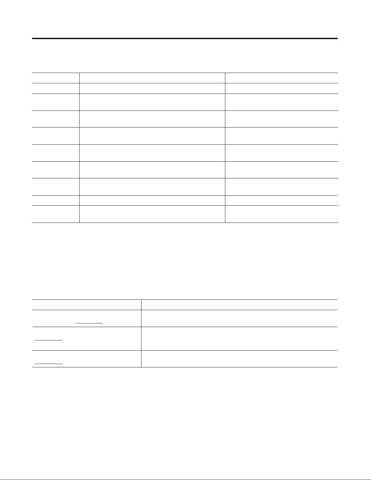
Page 3
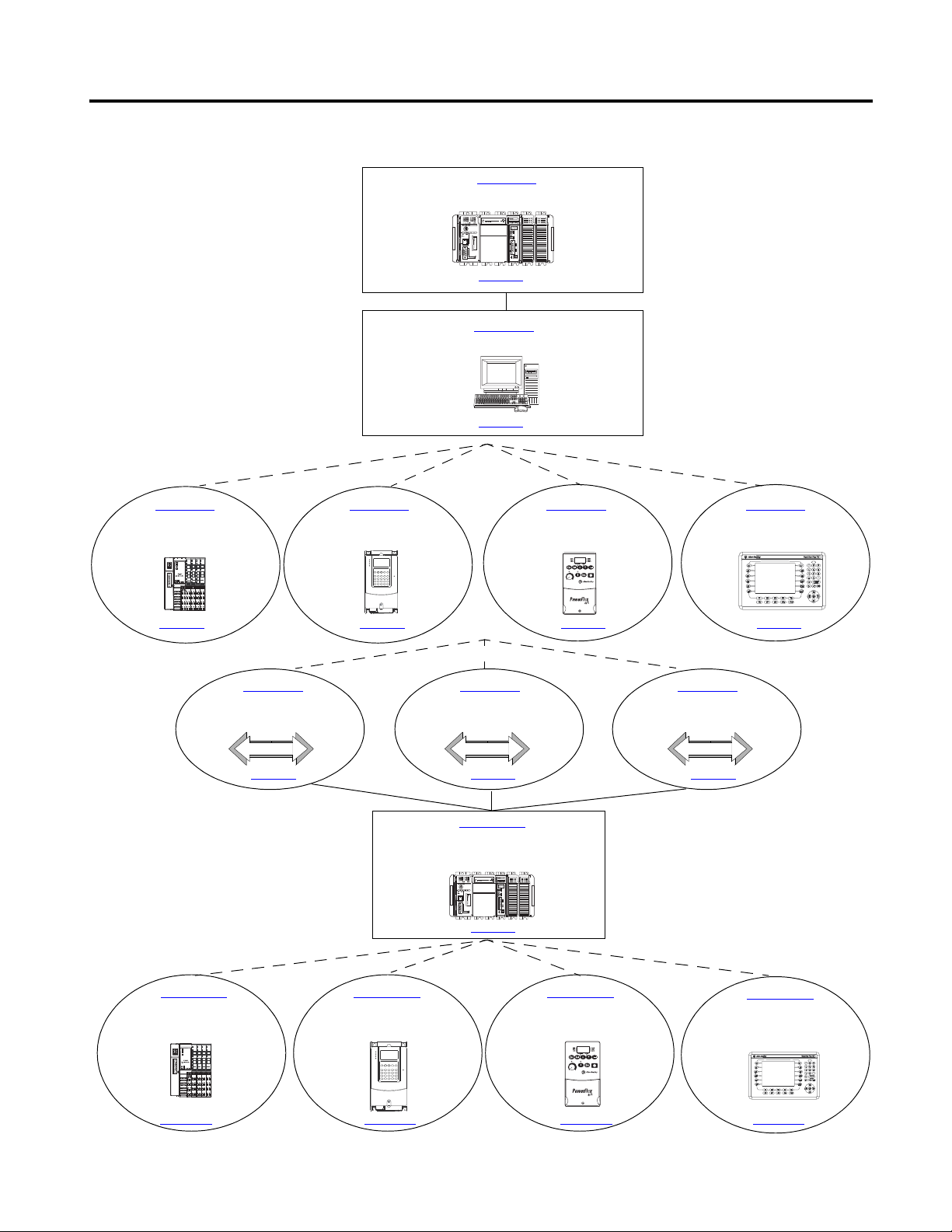
Follow the path that matches your hardware and network configuration.
Chapter 10
Create a Project Using RSLogix 5000
Programming Software
Chapter 1
Prepare the CompactLogix Hardware
Chapter 2
Prepare the Computer
Chapter 3
Prepare the Distributed
POINT I/O Hardware
Chapter 4
Prepare the PowerFlex 70
Drive
Chapter 5
Prepare the PowerFlex 40
Drive
Chapter 6
Prepare the PanelView Plus
Terminal
Chapter 7
Configure the EtherNet/IP
Network
Chapter 8
Configure the ControlNet
Driver
Chapter 9
Configure the DeviceNet
Network
Chapter 11
Add Distributed I/O
Modules to the Project
Chapter 12
Create a PowerFlex 70
Application
Chapter 13
Create a PowerFlex 40
Application
Chapter 14
Create a PanelView Plus
Application
Required
Required
Optional
Depending on your system.
Optional
Depending on
your networks.
Required
Optional
Depending on your system.
page 17
page 27
page 55 page 63page 47 page 71
page 81 page 87 page 91
page 99
page 113 page 143 page 167 page 189
Where to Start
3Publication IASIMP-QS001C-EN-P - October 2009 3
Page 4
Where to Start
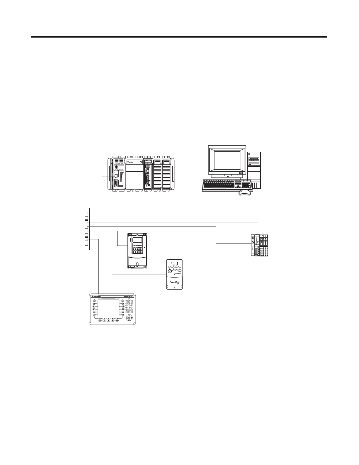
PanelView Plus terminal
with built-in EtherNet/IP
Ethernet
Switch
1769-L32E or 1769-L35E
with Optional 1769-SDN for the
DeviceNet Network
Serial (CP3 Cable)
PowerFlex 70 Drive
with 20-COMM-E
PowerFlex 40 Drive
with 22-COMM-E
PanelView Plus Terminal
with Built-in EtherNet/IP
Port
Computer with
Standard Ethernet Port
Distributed
POINT I/O
Modules with
1734-AENT
How Hardware is Connected
This quick start demonstrates the following possible control systems. Choose your hardware
and networks, then follow the matching examples.
Option 1: 1769-L32E, 1769-L35E Control System
4 Publication IASIMP-QS001C-EN-P - October 2009
Page 5
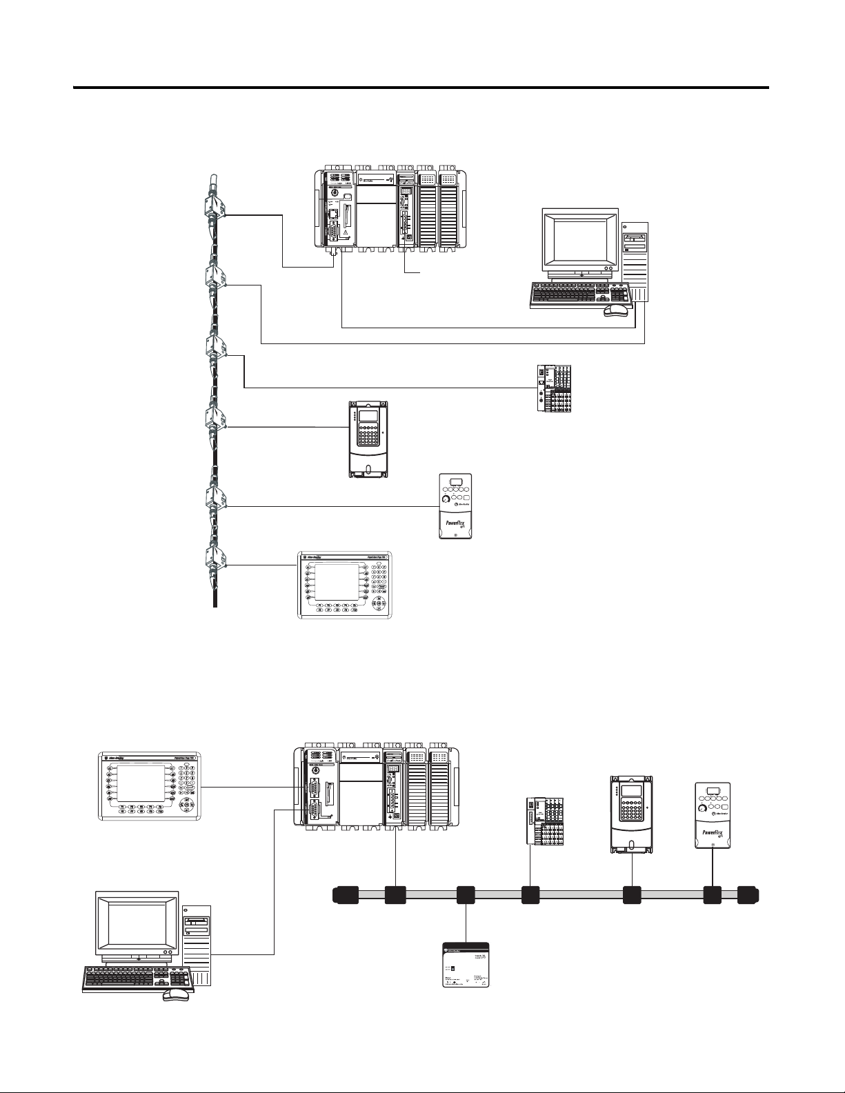
Option 2: 1769-L32C, 1769-L35CR Control System
ControlNet Network
with Taps
1769-L32C or 1769-L35CR
with Optional 1769-SDN for the DeviceNet
Network
PowerFlex 70 Drive
with 20-COMM-C
PowerFlex 40 Drive
with 22-COMM-C
PanelView Plus Terminal with
ControlNet Communication Adapter
Computer with
1784-PCIC, -PCICS
ControlNet
Communication Card
Distributed 1734
POINT I/O Modules
with 1734-ACNR
Serial (CP3 Cable)
To Optional
DeviceNet
Network
1769-L31 with 1769-SDN
1756-CP3 Serial Cable to
CH0 on 1769-L31
DeviceNet Network with
KwikLink
Flat Cable and Micro Connectors
PowerFlex 70
Drive with
20-COMM-D
PowerFlex 40
Drive with
22-COMM-D
PanelView Plus Terminal with
2706-NC13 Serial Cable to
CH1 on 1769-L31
Distributed 1734
POINT I/O
Modules with
1734-ADN
DeviceNet
Power Supply
1606-XLDNET8
Where to Start
Option 3: 1769-L31 Control System
Publication IASIMP-QS001C-EN-P - October 2009 5
Page 6

Where to Start
Notes:
6 Publication IASIMP-QS001C-EN-P - October 2009
Page 7

Preface Preface
About This Publication . . . . . . . . . . . . . . . . . . . . . . . . . . . . . . . . . . . . . 11
Required Software . . . . . . . . . . . . . . . . . . . . . . . . . . . . . . . . . . . . . . . . . 12
Parts List. . . . . . . . . . . . . . . . . . . . . . . . . . . . . . . . . . . . . . . . . . . . . . . . . 13
Conventions . . . . . . . . . . . . . . . . . . . . . . . . . . . . . . . . . . . . . . . . . . . . . . 15
Additional Resources . . . . . . . . . . . . . . . . . . . . . . . . . . . . . . . . . . . . . . . 15
Chapter 1
Prepare the CompactLogix
Hardware
Before You Begin. . . . . . . . . . . . . . . . . . . . . . . . . . . . . . . . . . . . . . . . . . 17
What You Need . . . . . . . . . . . . . . . . . . . . . . . . . . . . . . . . . . . . . . . . . . . 17
Follow These Steps . . . . . . . . . . . . . . . . . . . . . . . . . . . . . . . . . . . . . . . . 18
Connect the Battery to the Controller. . . . . . . . . . . . . . . . . . . . . . . . . . 19
Record the Ethernet Address (MAC) . . . . . . . . . . . . . . . . . . . . . . . . . . 19
Set the ControlNet Node Address . . . . . . . . . . . . . . . . . . . . . . . . . . . . 20
Assemble the System . . . . . . . . . . . . . . . . . . . . . . . . . . . . . . . . . . . . . . . 21
Make Network Connections . . . . . . . . . . . . . . . . . . . . . . . . . . . . . . . . . 22
Wire Power. . . . . . . . . . . . . . . . . . . . . . . . . . . . . . . . . . . . . . . . . . . . . . . 25
Additional Resources . . . . . . . . . . . . . . . . . . . . . . . . . . . . . . . . . . . . . . . 26
Table of Contents
Prepare the Computer
Prepare the Distributed POINT I/O
Hardware
Chapter 2
Before You Begin. . . . . . . . . . . . . . . . . . . . . . . . . . . . . . . . . . . . . . . . . . 27
What You Need . . . . . . . . . . . . . . . . . . . . . . . . . . . . . . . . . . . . . . . . . . . 27
Terminology . . . . . . . . . . . . . . . . . . . . . . . . . . . . . . . . . . . . . . . . . . . . . . 29
Make Network Connections . . . . . . . . . . . . . . . . . . . . . . . . . . . . . . . . . 29
Install RSLogix Programming Software . . . . . . . . . . . . . . . . . . . . . . . . 31
Configure a Serial Driver . . . . . . . . . . . . . . . . . . . . . . . . . . . . . . . . . . . . 36
Set the IP Address for the Computer . . . . . . . . . . . . . . . . . . . . . . . . . . 38
Configure the EtherNet/IP Driver in RSLinx Software . . . . . . . . . . . 40
Load Firmware . . . . . . . . . . . . . . . . . . . . . . . . . . . . . . . . . . . . . . . . . . . . 42
Install Additional Software . . . . . . . . . . . . . . . . . . . . . . . . . . . . . . . . . . 44
Additional Resources . . . . . . . . . . . . . . . . . . . . . . . . . . . . . . . . . . . . . . . 45
Chapter 3
Before You Begin. . . . . . . . . . . . . . . . . . . . . . . . . . . . . . . . . . . . . . . . . . 47
What You Need . . . . . . . . . . . . . . . . . . . . . . . . . . . . . . . . . . . . . . . . . . . 47
Follow These Steps . . . . . . . . . . . . . . . . . . . . . . . . . . . . . . . . . . . . . . . . 48
Mount and Connect the Network Adapter. . . . . . . . . . . . . . . . . . . . . . 49
Mount the POINT I/O Modules . . . . . . . . . . . . . . . . . . . . . . . . . . . . . 51
Mount and Wire the POINT I/O Power Supply. . . . . . . . . . . . . . . . . 52
Wire the Adapter and I/O Modules to the Power Supply. . . . . . . . . . 53
Additional Resources . . . . . . . . . . . . . . . . . . . . . . . . . . . . . . . . . . . . . . . 53
Chapter 4
Prepare the PowerFlex 70 Drive
7Publication IASIMP-QS001C-EN-P - October 2009 7
Before You Begin. . . . . . . . . . . . . . . . . . . . . . . . . . . . . . . . . . . . . . . . . . 55
What You Need . . . . . . . . . . . . . . . . . . . . . . . . . . . . . . . . . . . . . . . . . . . 55
Follow These Steps . . . . . . . . . . . . . . . . . . . . . . . . . . . . . . . . . . . . . . . . 56
Page 8

Table of Contents
Prepare the PowerFlex 40 Drive
Prepare the PanelView Plus
Terminal
Mount the PowerFlex 70 Drive. . . . . . . . . . . . . . . . . . . . . . . . . . . . . . . 57
Wire Power. . . . . . . . . . . . . . . . . . . . . . . . . . . . . . . . . . . . . . . . . . . . . . . 57
Configure the Communication Adapter . . . . . . . . . . . . . . . . . . . . . . . . 58
Connect Communication Adapter to the PowerFlex 70 Drive . . . . . . 59
Additional Resources . . . . . . . . . . . . . . . . . . . . . . . . . . . . . . . . . . . . . . . 61
Chapter 5
Before You Begin. . . . . . . . . . . . . . . . . . . . . . . . . . . . . . . . . . . . . . . . . . 63
What You Need . . . . . . . . . . . . . . . . . . . . . . . . . . . . . . . . . . . . . . . . . . . 63
Follow These Steps . . . . . . . . . . . . . . . . . . . . . . . . . . . . . . . . . . . . . . . . 64
Mount the PowerFlex 40 Drive. . . . . . . . . . . . . . . . . . . . . . . . . . . . . . . 65
Wire Power. . . . . . . . . . . . . . . . . . . . . . . . . . . . . . . . . . . . . . . . . . . . . . . 65
Configure the Communication Adapter . . . . . . . . . . . . . . . . . . . . . . . . 66
Connect the Communication Adapter to the PowerFlex 40 Drive. . . 67
Additional Resources . . . . . . . . . . . . . . . . . . . . . . . . . . . . . . . . . . . . . . . 69
Chapter 6
Before You Begin. . . . . . . . . . . . . . . . . . . . . . . . . . . . . . . . . . . . . . . . . . 71
What You Need . . . . . . . . . . . . . . . . . . . . . . . . . . . . . . . . . . . . . . . . . . . 71
Follow These Steps . . . . . . . . . . . . . . . . . . . . . . . . . . . . . . . . . . . . . . . . 72
Install the ControlNet Interface Module . . . . . . . . . . . . . . . . . . . . . . . 73
Mount the PanelView Plus Terminal . . . . . . . . . . . . . . . . . . . . . . . . . . 73
Wire the PanelView Plus Terminal to the Power Supply. . . . . . . . . . . 74
Make Network Connections . . . . . . . . . . . . . . . . . . . . . . . . . . . . . . . . . 75
Assign an IP Address. . . . . . . . . . . . . . . . . . . . . . . . . . . . . . . . . . . . . . . 77
Additional Resources . . . . . . . . . . . . . . . . . . . . . . . . . . . . . . . . . . . . . . . 80
Chapter 7
Configure the EtherNet/IP
Network
Before You Begin. . . . . . . . . . . . . . . . . . . . . . . . . . . . . . . . . . . . . . . . . . 81
What You Need . . . . . . . . . . . . . . . . . . . . . . . . . . . . . . . . . . . . . . . . . . . 81
Follow These Steps . . . . . . . . . . . . . . . . . . . . . . . . . . . . . . . . . . . . . . . . 82
Terminology . . . . . . . . . . . . . . . . . . . . . . . . . . . . . . . . . . . . . . . . . . . . . . 82
Assign IP Addresses to Devices . . . . . . . . . . . . . . . . . . . . . . . . . . . . . . 83
Browse the EtherNet/IP Network in RSLinx . . . . . . . . . . . . . . . . . . . 85
Additional Resources . . . . . . . . . . . . . . . . . . . . . . . . . . . . . . . . . . . . . . . 85
Chapter 8
Configure the ControlNet Driver
8 Publication IASIMP-QS001C-EN-P - October 2009
Before You Begin. . . . . . . . . . . . . . . . . . . . . . . . . . . . . . . . . . . . . . . . . . 87
What You Need . . . . . . . . . . . . . . . . . . . . . . . . . . . . . . . . . . . . . . . . . . . 87
Follow These Steps . . . . . . . . . . . . . . . . . . . . . . . . . . . . . . . . . . . . . . . . 87
Configure the ControlNet Driver in RSLinx . . . . . . . . . . . . . . . . . . . . 88
Additional Resources . . . . . . . . . . . . . . . . . . . . . . . . . . . . . . . . . . . . . . . 90
Page 9

Configure the DeviceNet Network
Create a Project Using RSLogix
5000 Programming Software
Table of Contents
Chapter 9
Before You Begin. . . . . . . . . . . . . . . . . . . . . . . . . . . . . . . . . . . . . . . . . . 91
What You Need . . . . . . . . . . . . . . . . . . . . . . . . . . . . . . . . . . . . . . . . . . . 91
Follow These Steps . . . . . . . . . . . . . . . . . . . . . . . . . . . . . . . . . . . . . . . . 92
Apply Power to the DeviceNet Network . . . . . . . . . . . . . . . . . . . . . . . 93
Set the 1769-SDN Module’s Node Address. . . . . . . . . . . . . . . . . . . . . 94
Create a DeviceNet Configuration File. . . . . . . . . . . . . . . . . . . . . . . . . 96
Additional Resources . . . . . . . . . . . . . . . . . . . . . . . . . . . . . . . . . . . . . . . 98
Chapter 10
Before You Begin. . . . . . . . . . . . . . . . . . . . . . . . . . . . . . . . . . . . . . . . . . 99
What You Need . . . . . . . . . . . . . . . . . . . . . . . . . . . . . . . . . . . . . . . . . . . 99
Follow These Steps . . . . . . . . . . . . . . . . . . . . . . . . . . . . . . . . . . . . . . . 100
Create a Project . . . . . . . . . . . . . . . . . . . . . . . . . . . . . . . . . . . . . . . . . . 101
Configure the Controller . . . . . . . . . . . . . . . . . . . . . . . . . . . . . . . . . . . 103
Add Local I/O Modules . . . . . . . . . . . . . . . . . . . . . . . . . . . . . . . . . . . 105
Add Ladder Logic to Test the Local 1769 Compact I/O Modules. . 106
Set the Communication Path and Download to the Controller . . . . 109
Add the 1769-SDN to the Project. . . . . . . . . . . . . . . . . . . . . . . . . . . . 111
Additional Resources . . . . . . . . . . . . . . . . . . . . . . . . . . . . . . . . . . . . . . 112
Add Distributed I/O Modules to the
Project
Create a PowerFlex 70 Application
Chapter 11
Before You Begin. . . . . . . . . . . . . . . . . . . . . . . . . . . . . . . . . . . . . . . . . 113
What You Need . . . . . . . . . . . . . . . . . . . . . . . . . . . . . . . . . . . . . . . . . . 113
Follow These Steps . . . . . . . . . . . . . . . . . . . . . . . . . . . . . . . . . . . . . . . 114
Add Distributed I/O Modules . . . . . . . . . . . . . . . . . . . . . . . . . . . . . . 115
Edit the DeviceNet Adapter Parameters . . . . . . . . . . . . . . . . . . . . . . 118
Configure the DeviceNet Subnet . . . . . . . . . . . . . . . . . . . . . . . . . . . . 120
Create a DeviceNet Scanlist. . . . . . . . . . . . . . . . . . . . . . . . . . . . . . . . . 124
Add Ladder Logic . . . . . . . . . . . . . . . . . . . . . . . . . . . . . . . . . . . . . . . . 127
Create DeviceNet Tags and Add Ladder Logic . . . . . . . . . . . . . . . . . 129
Download the Project . . . . . . . . . . . . . . . . . . . . . . . . . . . . . . . . . . . . . 134
Set the POINT I/O Chassis Size . . . . . . . . . . . . . . . . . . . . . . . . . . . . 135
Schedule the ControlNet Network . . . . . . . . . . . . . . . . . . . . . . . . . . . 137
Test the Distributed I/O Light . . . . . . . . . . . . . . . . . . . . . . . . . . . . . . 141
Additional Resources . . . . . . . . . . . . . . . . . . . . . . . . . . . . . . . . . . . . . . 142
Chapter 12
Before You Begin. . . . . . . . . . . . . . . . . . . . . . . . . . . . . . . . . . . . . . . . . 143
What You Need . . . . . . . . . . . . . . . . . . . . . . . . . . . . . . . . . . . . . . . . . . 143
Follow These Steps . . . . . . . . . . . . . . . . . . . . . . . . . . . . . . . . . . . . . . . 144
Add the Drive to Your RSLogix 5000 Project and Connect
to the Drive . . . . . . . . . . . . . . . . . . . . . . . . . . . . . . . . . . . . . . . . . . 145
Edit the Drive Parameters . . . . . . . . . . . . . . . . . . . . . . . . . . . . . . . . . . 149
Create a DeviceNet Scanlist. . . . . . . . . . . . . . . . . . . . . . . . . . . . . . . . . 150
Publication IASIMP-QS001C-EN-P - October 2009 9
Page 10

Table of Contents
Create a PowerFlex 40 Application
Create DeviceNet Tags . . . . . . . . . . . . . . . . . . . . . . . . . . . . . . . . . . . . 154
Download the Project . . . . . . . . . . . . . . . . . . . . . . . . . . . . . . . . . . . . . 156
Schedule the ControlNet Network . . . . . . . . . . . . . . . . . . . . . . . . . . . 157
Test the PowerFlex 70 Tags . . . . . . . . . . . . . . . . . . . . . . . . . . . . . . . . 161
Test the PowerFlex 70 Tags . . . . . . . . . . . . . . . . . . . . . . . . . . . . . . . . 163
Additional Resources . . . . . . . . . . . . . . . . . . . . . . . . . . . . . . . . . . . . . . 165
Chapter 13
Before You Begin. . . . . . . . . . . . . . . . . . . . . . . . . . . . . . . . . . . . . . . . . 167
What You Need . . . . . . . . . . . . . . . . . . . . . . . . . . . . . . . . . . . . . . . . . . 167
Follow These Steps . . . . . . . . . . . . . . . . . . . . . . . . . . . . . . . . . . . . . . . 168
Add the Drive to Your RSLogix 5000 Project . . . . . . . . . . . . . . . . . . 169
Create a DeviceNet Scanlist. . . . . . . . . . . . . . . . . . . . . . . . . . . . . . . . . 171
Create DeviceNet Tags . . . . . . . . . . . . . . . . . . . . . . . . . . . . . . . . . . . . 174
Download the Project . . . . . . . . . . . . . . . . . . . . . . . . . . . . . . . . . . . . . 176
Schedule the ControlNet Network . . . . . . . . . . . . . . . . . . . . . . . . . . . 177
Edit PowerFlex 40 Parameter Values . . . . . . . . . . . . . . . . . . . . . . . . . 181
Reference for Editing Parameters . . . . . . . . . . . . . . . . . . . . . . . . 181
Test the PowerFlex 40 Tags . . . . . . . . . . . . . . . . . . . . . . . . . . . . . . . . 183
Test the PowerFlex 40 Tags . . . . . . . . . . . . . . . . . . . . . . . . . . . . . . . . 185
Additional Resources . . . . . . . . . . . . . . . . . . . . . . . . . . . . . . . . . . . . . . 187
Create a PanelView Plus
Application
Network Worksheet
Chapter 14
Before You Begin. . . . . . . . . . . . . . . . . . . . . . . . . . . . . . . . . . . . . . . . . 189
What You Need . . . . . . . . . . . . . . . . . . . . . . . . . . . . . . . . . . . . . . . . . . 189
Follow These Steps . . . . . . . . . . . . . . . . . . . . . . . . . . . . . . . . . . . . . . . 190
Create a New Application . . . . . . . . . . . . . . . . . . . . . . . . . . . . . . . . . . 191
Create an RSLinx Enterprise Configuration in
FactoryTalkView ME . . . . . . . . . . . . . . . . . . . . . . . . . . . . . . . . . . . 192
Create Device Shortcuts to the Controller . . . . . . . . . . . . . . . . . . . . . 194
Create the OB16_Light Indicator . . . . . . . . . . . . . . . . . . . . . . . . . . . . 199
Create a Push Button . . . . . . . . . . . . . . . . . . . . . . . . . . . . . . . . . . . . . . 202
Test the Indicator and Push Button . . . . . . . . . . . . . . . . . . . . . . . . . . 204
Add a Goto Configuration Mode Button . . . . . . . . . . . . . . . . . . . . . . 206
Assign Keys . . . . . . . . . . . . . . . . . . . . . . . . . . . . . . . . . . . . . . . . . . . . . 207
Assign an Initial Screen . . . . . . . . . . . . . . . . . . . . . . . . . . . . . . . . . . . . 208
Transfer to PanelView Plus Firmware . . . . . . . . . . . . . . . . . . . . . . . . 209
Test the Application on the PanelView Plus Application . . . . . . . . . 211
Additional Resources . . . . . . . . . . . . . . . . . . . . . . . . . . . . . . . . . . . . . . 212
EtherNet/IP. . . . . . . . . . . . . . . . . . . . . . . . . . . . . . . . . . . . . . . . . . . . . 213
DeviceNet Network. . . . . . . . . . . . . . . . . . . . . . . . . . . . . . . . . . . . . . . 213
1769-SDN Module Information . . . . . . . . . . . . . . . . . . . . . . . . . . . . . 213
RSNetWorx DeviceNet Configuration File Information. . . . . . . . . . 213
ControlNet Network . . . . . . . . . . . . . . . . . . . . . . . . . . . . . . . . . . . . . . 214
10 Publication IASIMP-QS001C-EN-P - October 2009
Page 11

Preface
About This Publication
This quick start provides examples and procedures for the use of a
CompactLogix system. This publication includes version 18 release updates
for RSLogix 5000 programming software. The procedures cover many of the
most common user tasks, such as:
• connecting the controller to multiple devices (local and distributed I/O,
drives, and a PanelView Plus terminal).
• connecting and configuring networks (EtherNet/IP, ControlNet,
DeviceNet, and serial) for use with CompactLogix systems.
• creating and monitoring controller programs.
The examples are designed to get devices installed and communicating with
each other in the simplest way possible. The programming examples are not
complex, and offer easy solutions to verify that devices are functioning and
communicating properly.
The beginning of each chapter contains the following information. Read these
sections carefully before beginning work in each chapter.
• Before You Begin - This section lists the steps that must be completed
and decisions that must be made before starting the chapter. Because
the chapters in this quick start do not have to be completed in the order
in which they appear, this section defines the minimum amount of
preparation required before completing the current chapter.
• What You Need - This section lists the tools that are required to
complete the steps in the current chapter. This includes, but is not
limited to, hardware and software.
• Follow These Steps - This illustrates the steps in the current chapter
and identifies which steps are required to complete the examples by
using specific networks.
The electronic version of this publication contains links to pages within the
publication for easier navigation. Click on any chapter title, chapter number,
topic title, or page number to follow a link to the item.
Additionally, resources available on the Web and listed in the Additional
Resources tables function as hyperlinks within this electronic publication.
Publication IASIMP-QS001C-EN-P - October 2009 11
Page 12

Required Software
To complete examples in this quick start, you need one of the following
software packages.
If using network Use RSLogix 5000 programming
software edition
EtherNet/IP
(Options 1, 2, and 3)
ControlNet
(Option 2)
DeviceNet
(Option 3)
•Full
•Standard
•Professional
•Standard
•Professional
•Standard
•Professional
If you do not use the RSLogix 5000 programming software packages
recommended, you may need to purchase additional software to complete the
examples in this quick start.
You will need to install the following software, included with the RSLogix
5000 programming software packages listed:
• BootP-DHCP server
• ControlFlash software
• DeviceNet Tag Generator
• RSLinx software, version 2.54 or later
• RSLogix 5000 programming software, version 17 or later
• RSNetWorx software (version specific to your network option)
If you plan to complete the PanelView Plus examples within this quick start,
you will also need FactoryTalkView Machine Edition software.
12 Publication IASIMP-QS001C-EN-P - October 2009
Page 13

Parts List
This table lists the hardware used in this quick start. The hardware you need
depends on the options and examples you choose to complete. Specific
hardware requirements are listed at the beginning of each chapter.
Quantity Catalog Number Description
General Configuration
1 1769-IF4 Compact 4 Channel Analog Current/Voltage Input Module
1 1769-IQ16 Compact 16 Point 24V DC Sinking/Sourcing Input Module
1 1769-IF4XOF2 Compact 8 Bit Resolution, High Speed 4 In/2 Out Analog Combination Module
1 1769-OF2 Compact 2 Channel Analog Current/Voltage Output Module
1
1 1769-PA2 Compact Expansion Power Supply 120/240V AC Input 2 A @ 5V DC Output Module
1 1769-ECR Compact I/O Right End Cap/Terminator
1
1
1
3 1734-TB Wiring Base w/ Removable IEC Screw Terminals
1 1794-PS13 FLEX I/O 85 - 264V AC to 24V DC 1.3 A Power Supply
1 22B-V2P3N104 PowerFlex 40 Drive
1769-OB16
1734-IB4
1734-OB4E
1734-OE2C
(1)
(2)
(2)(3)
(2)
Compact 16 Point 24V DC Sourcing Output Module
POINT I/O 4 Sink Input Module
POINT I/O 4 Protected Output Module
POINT I/O 2 Current Output Analog Module
1 22B-CCB PowerFlex 40 Communication Adapter Cover
1 20AB4P2A3AYNNNNN PowerFlex 70 Drive
1 2711P-K10C4D1 PanelView Plus 10 inch Color Keypad Terminal with EtherNet/IP and RS-232 networks
1 1794-PS3 or
2711P-RSACDIN
2 1756-CP3 RS-232 Cable
1 2706-NC13 PanelView Plus Serial Cable
2...3 N/A DIN Rail (steel not aluminum)
EtherNet/IP Configuration
1 1769-L32E CompactLogix EtherNet/IP Controller
1 1734-AENT POINT I/O EtherNet/IP Adapter
1 22-COMM-E EtherNet/IP Adapter for Use With the PowerFlex 40
1 20-COMM-E EtherNet/IP Adapter for Use With the PowerFlex 70
1 N/A 8-Port Ethernet Switch
6 N/A Ethernet Cables (straight through)
FLEX I/O DC Power Supply or general use AC Power Supply
Publication IASIMP-QS001C-EN-P - October 2009 13
Page 14

Quantity Catalog Number Description
ControlNet Configuration
1 1769-L32CR CompactLogix ControlNet Controller with Redundant Tap
1 1784-PCIC or 1784-PCICS ControlNet Communication Card for a Personal Computer
1 1734-ACNR POINT I/O ControlNet Adapter
1 22-COMM-C ControlNet Adapter for Use With the PowerFlex 40
1 20-COMM-C ControlNet Adapter for Use With the PowerFlex 70
1 2711P-RN15S PanelView Plus 1000 ControlNet Interface Module
6 1786-TPR ControlNet Tap
2 1786-XT ControlNet Terminating Resistor
5 1786-BNCP ControlNet BNC Coaxial Connector
Serial Configuration
1 1769-L31 1769-L31 CompactLogix Controller
1 1756-CP3 RS-232 cable
1 2706-NC13 Point-to-Point RS-232 Cable
DeviceNet Configuration
1 1769-SDN Compact I/O DeviceNet Scanner
1 1734-ADN POINT I/O DeviceNet Adapter
1 22-COMM-D DeviceNet Adapter for use with the PowerFlex 40
1 20-COMM-D DeviceNet Adapter for use with the PowerFlex 70
1 1606-XLDNET8 DeviceNet Power Supply
N/A 1485C-P1E75 KwikLink Flat Cable
2 1485A-T1E4 KwikLink Terminator/Resistor
4 1485P-P1E4-R5 KwikLink Sealed Micro Connector
4 1485K-P1F5-C KwikLink Right-angle Male to Cable
1 1485T-P1E4-B1 KwikLink Power Tap Module
(1)
The 1769-OB16 module is the only Compact I/O module used in this quick start. The other modules are added as examples only and are not required.
(2)
Use Point I/O modules at series C or later to complete examples in this quick start.
(3)
The 1734-OB4E module is the only POINT I/O module used in this quick start. The other modules are added as examples only and are not required.
14 Publication IASIMP-QS001C-EN-P - October 2009
Page 15
Conventions
Convention Meaning Example
bold Bold text denotes menus, menu items, buttons or options. Click OK.
Check/uncheck Click to activate/deactivate a checkbox. Check the Do not show this dialog again
Click Click left mouse button once. (Assumes cursor is positioned on
object or selection.)
Courier
font
Type or enter text exactly as shown. Type cmd.
This manual uses the following conventions.
checkbox.
Click Browse.
Double-click Click left mouse button twice in quick succession. (Assumes
cursor is positioned on object or selection.)
Expand Click the + to the left of a given item /folder to show its
contents.
Right-click Click right mouse button once. (Assumes cursor is positioned on
object or selection.)
Select Click to highlight a menu item or list choice. Select Properties from the drop-down list.
> Shows nested menu selections as menu name followed by menu
selection.
Double-click the H1 icon.
In the H1-1 window, expand the FFLD.
Right-click the Fieldbus Networks icon.
Click File
> Page Setup > Options.
Additional Resources
Resource Description
1769 CompactLogix Controllers Selection
Guide, publication 1769-SG001
Provides information and specifications for consideration when selecting CompactLogix
controllers and software.
1769 Compact I/O Selection Guide, publication
1769-SG002
NetLinx Selection Guide, publication
NETS-SG001
Provides information and specifications for consideration when selecting I/O modules
for use with the CompactLogix system. Includes Compact I/O, POINT I/O, and FLEX I/O
modules.
Provides information and specifications for consideration when selecting a network to
use and which hardware and cables you need.
Publication IASIMP-QS001C-EN-P - October 2009 15
Page 16

Notes:
16 Publication IASIMP-QS001C-EN-P - October 2009
Page 17

Chapter
1
Prepare the CompactLogix Hardware
In this chapter, you install your CompactLogix hardware, including the controller, power
supply, any local 1769 Compact I/O modules, and an optional 1769-SDN module (used only
if you have distributed I/O on the DeviceNet network)
Before You Begin
Determine which of these networks and appropriate hardware to use:
.
• For the EtherNet/IP network (option 1), use the 1769-L32E or 1769-L35E controller.
• For the ControlNet network (option 2), use the 1769-L32C or 1769-L35CR controller.
• For a serial connection (option 3), use the 1769-L31 controller.
• For the DeviceNet network (options 2 and 3), use the 1769-SDN module with the
1769-L31 controller.
What You Need
• CompactLogix controller: 1769-L32E, 1769-L35E, 1769-L32C, 1769-L35CR, or
1769-L31
• CompactLogix controller battery: 1769-BA (included with your controller)
• Compact power supply: 1769-PA2
• Compact I/O end cap: 1769-ECR
• Compact I/O module: this example uses a 1769-OB16 module. Other Compact I/O
modules can also be used, but are not required
• Compact I/O DeviceNet scanner module: 1769-SDN (only if you are using a
DeviceNet network)
• Network cable: Ethernet (commercially available), ControlNet (1786-TPR), or
serial (1756-CP3)
17Publication IASIMP-QS001C-EN-P - October 2009 17
Page 18
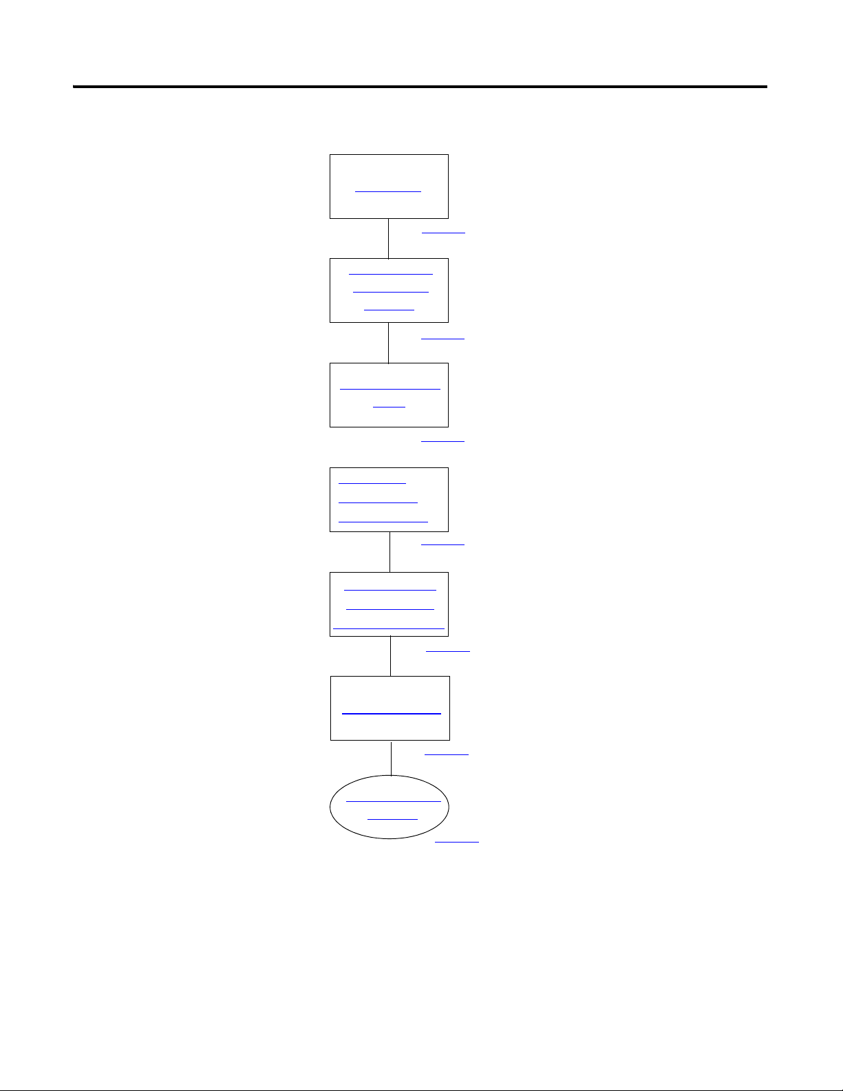
Chapter 1 Prepare the CompactLogix Hardware
Connect the
Battery to the
Controller
1769-L32E,
1769-L35E
1769-L32C,
1769-L35CR
1769-L31
Record the
Ethernet Address
(MAC)
Assemble the
System
Make Network
Connections
Wire Power
Connect the
Battery to the
Controller
Set the ControlNet
Node Address
Assemble the
System
Make Network
Connections
Wire Power
Connect the
Battery to the
Controller
Assemble the
System
Make Network
Connections
Wire Power
page 19
page 19
page 20
page 21
page 22
page 25
page 25
page 22
page 21
page 19
page 25
page 22
page 21
page 19
Follow These Steps
Complete the steps shown for your controller.
18 Publication IASIMP-QS001C-EN-P - October 2009
Page 19
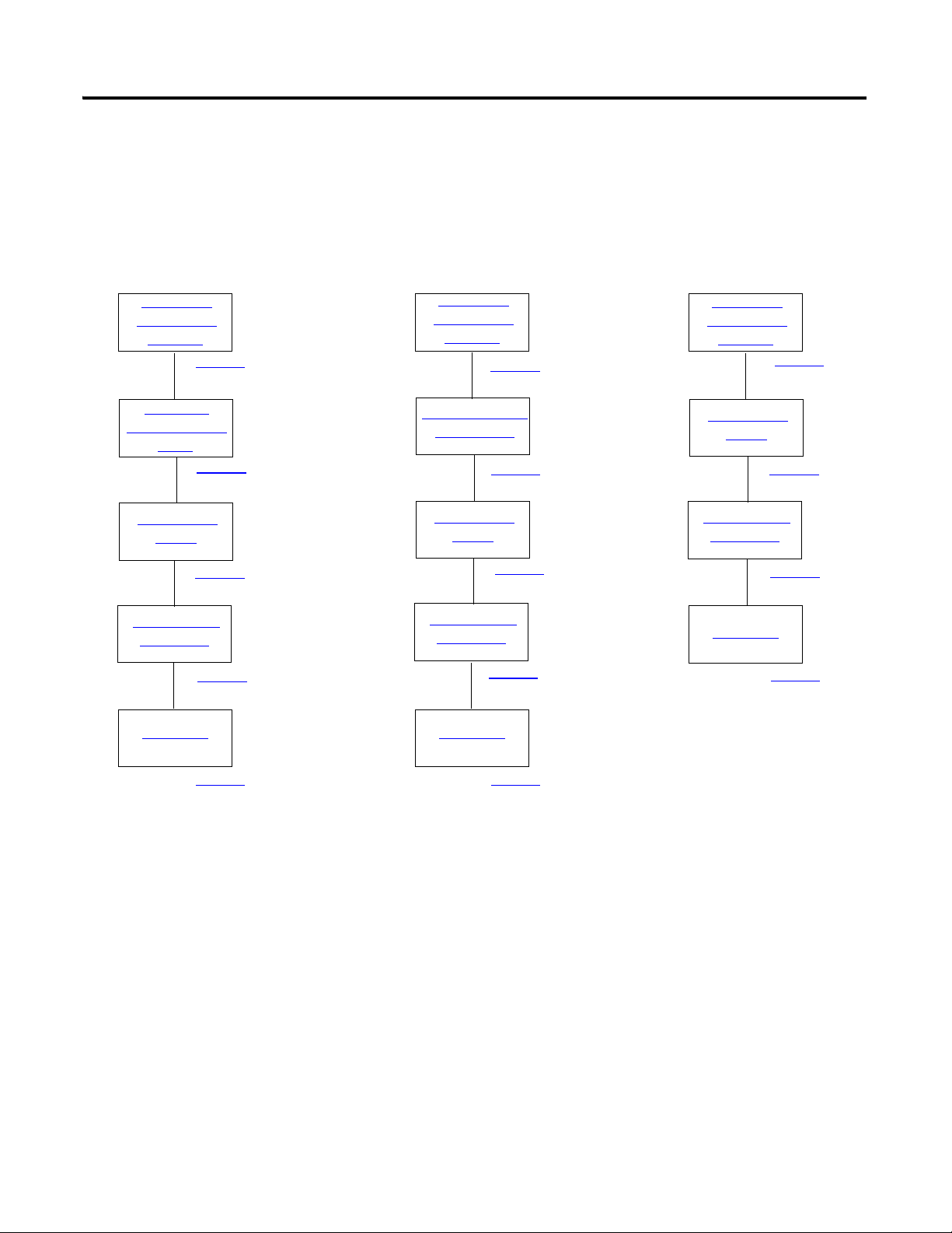
Connect the Battery to the Controller
1. Insert the battery and battery
connector.
2. Record the battery installation
date in the box provided on
the label.
Battery
Battery Connector
Ethernet Address
Box for Battery
Installation Date
00:00:BC:21:D7:BE
Ethernet Address
1769-BA Battery
Prepare the CompactLogix Hardware Chapter 1
Record the Ethernet Address (MAC)
1769-L32E or 1769-L35E controllers
The Ethernet address (MAC) is found on a label near the battery. This is an example address.
Record the Ethernet address (MAC) for the CompactLogix controller on the Network
Worksheet at the back of this quick start. This address is used to set the IP address later.
Publication IASIMP-QS001C-EN-P - October 2009 19
Page 20
Chapter 1 Prepare the CompactLogix Hardware
00
90
70
80
60
50
40
30
20
10
0
9
7
8
6
5
4
3
2
1
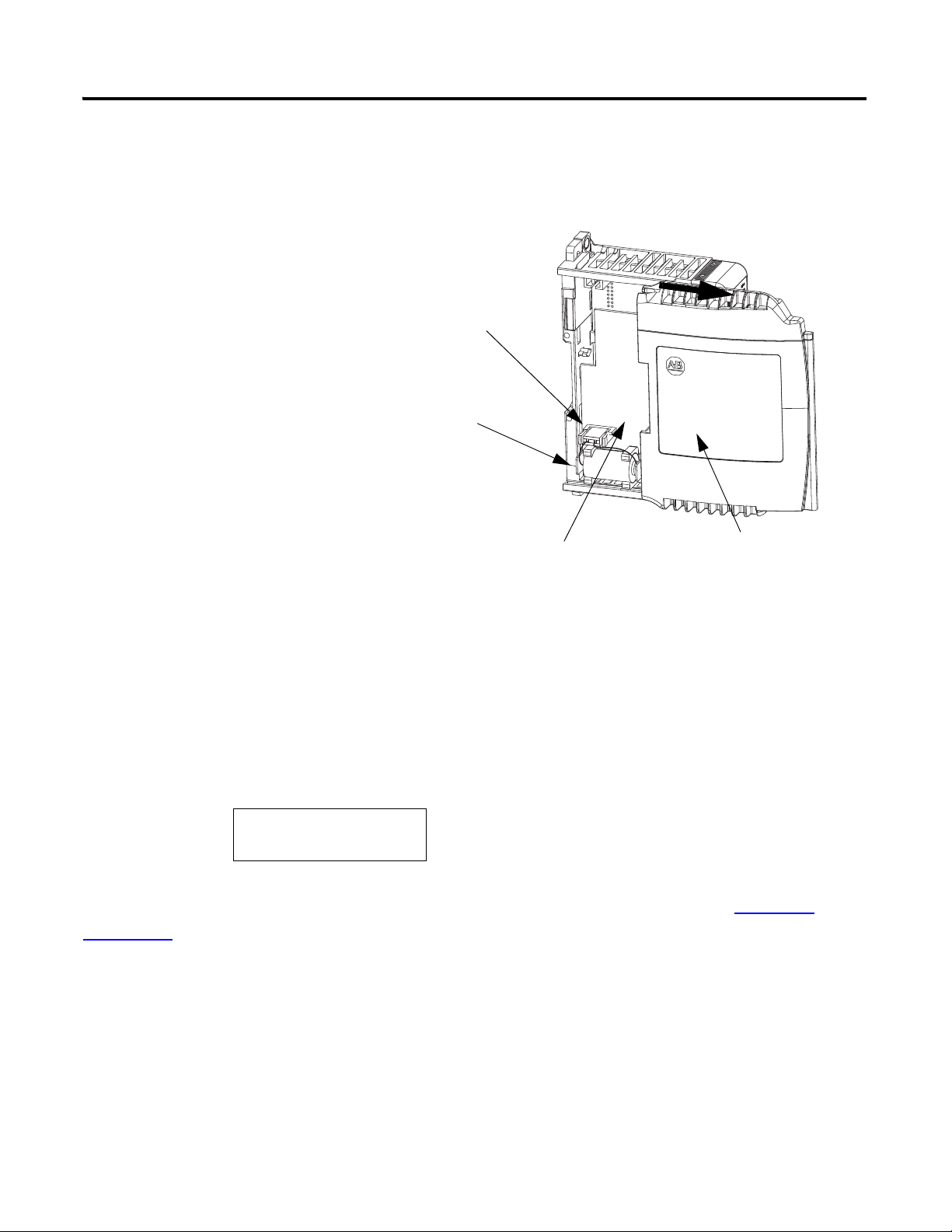
Tens
Digit
Ones
Digit
1. Use a small, flathead screwdriver to set the
node address to node 01.
2. Record the node address on the front panel
overlay.
Controllers are shipped with
the node address set at 99.
01 Shown
ControlNet Node Address Switches
Ones
Tens
Ones
Ten s
Set the ControlNet Node Address
1769-L32C or 1769-L35CR controllers
20 Publication IASIMP-QS001C-EN-P - October 2009
Page 21
Prepare the CompactLogix Hardware Chapter 1
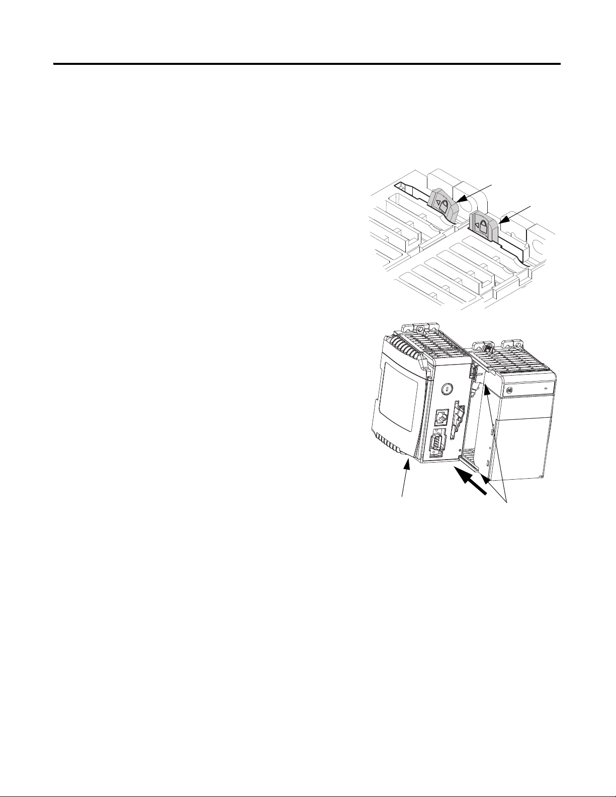
Unlocked
Locked
Tongue-and-groove Slots
1. On the top of each module, verify that all of the
locking tabs are unlocked.
2. Use the tongue-and-groove slots to slide the
power supply, then the I/O modules onto the
controller.
3. If you have an 1769-SDN module, record the
series letter (see label on the side of the module)
on the Network Worksheet inside the back cover
of this quick start.
4. If you have an 1769-SDN module, slide it onto
the other modules.
There can be a maximum of three modules
between the 1769-SDN module and the power
supply.
Controller
Assemble the System
Controller, power supply, local I/O modules, 1769-SDN module, end cap terminator
Publication IASIMP-QS001C-EN-P - October 2009 21
Page 22
Chapter 1 Prepare the CompactLogix Hardware
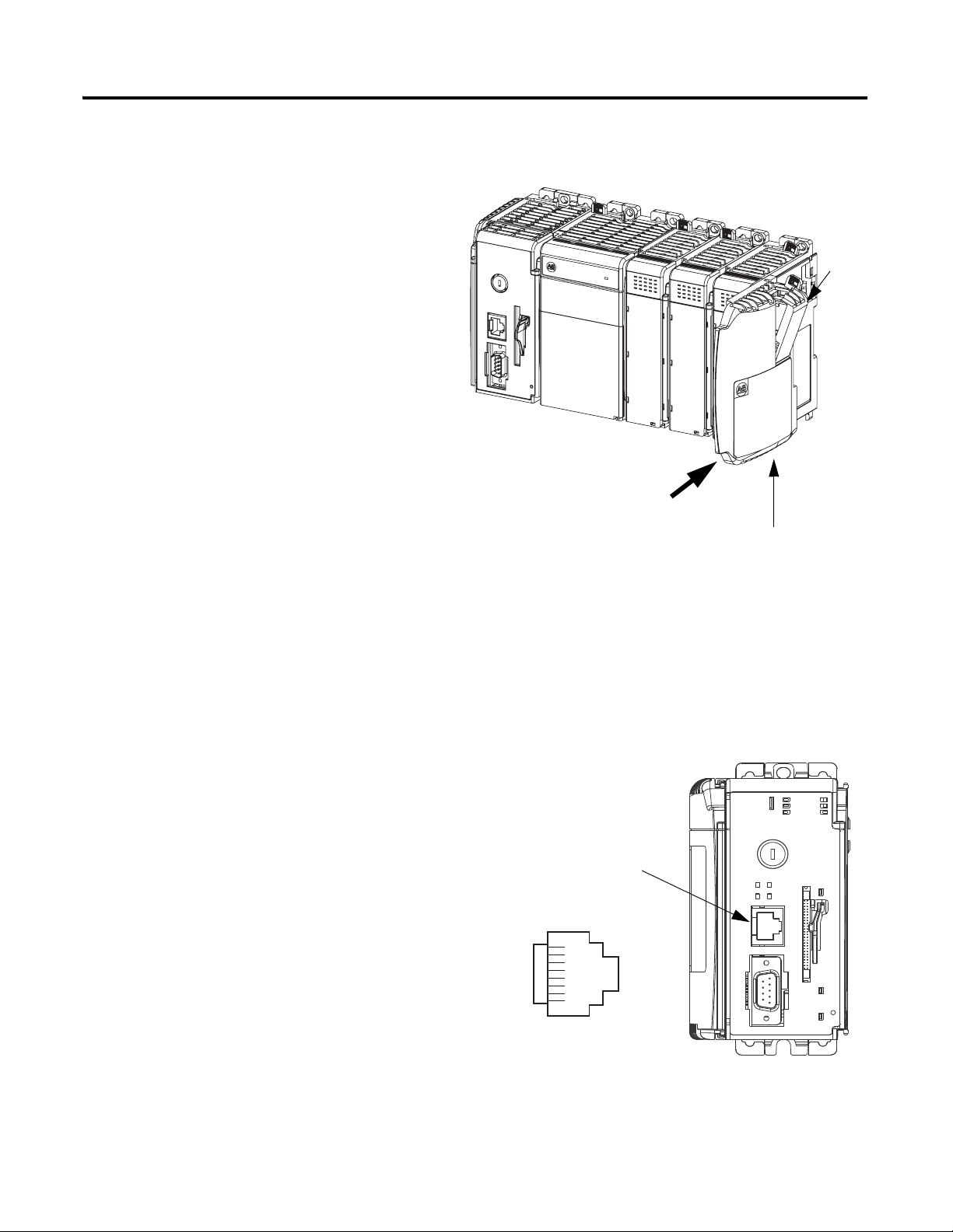
5. Lock all of the locking tabs on the top
of the modules.
6. Verify that the tabs are all the way to the
left.
7. Slide the end cap terminator on and
lock the locking tab.
8. Press the assembled system onto a DIN
rail.
Locking
Tab
End-cap Terminator
1. Insert an Ethernet cable with an RJ-45
connector.
2. Connect the other end of the cable to an
Ethernet switch
.
Ethernet Port
Make Network Connections
1769-L32E or 1769-L35E controllers
8 ------ NC
7 ------ NC
6 ------ RD5 ------ NC
4 ------ NC
3 ------ RD+
2 ------ TD1 ------ TD+
22 Publication IASIMP-QS001C-EN-P - October 2009
Page 23
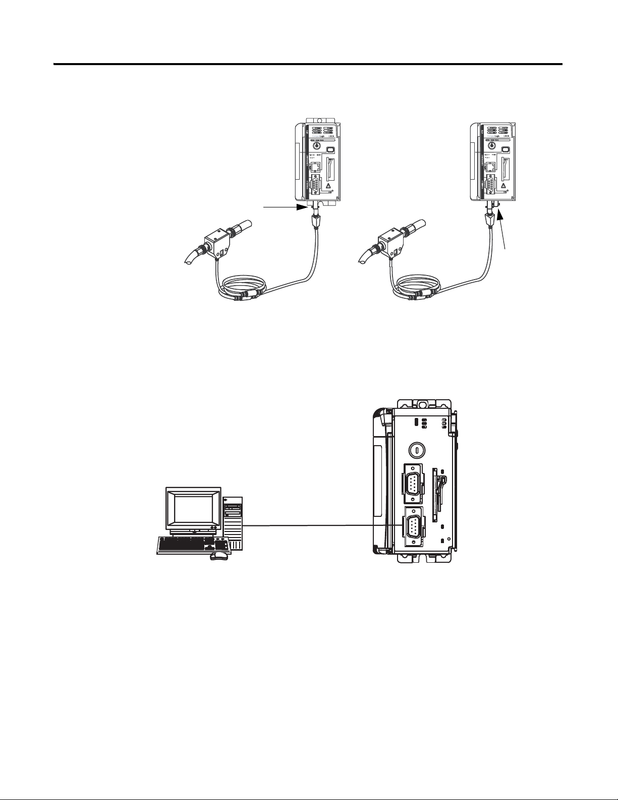
1769-L32C or 1769-L35CR controllers
A
B
A
Connect a ControlNet tap to port
A of the controller.
Port
A
Port B
(Do not use.)
1. Connect the 1756-CP3 cable to the channel
0 serial port on the controller.
2. Connect the other end of the cable to a
COM port on the computer.
Required for all CompactLogix controllers
Prepare the CompactLogix Hardware Chapter 1
Publication IASIMP-QS001C-EN-P - October 2009 23
Page 24
Chapter 1 Prepare the CompactLogix Hardware
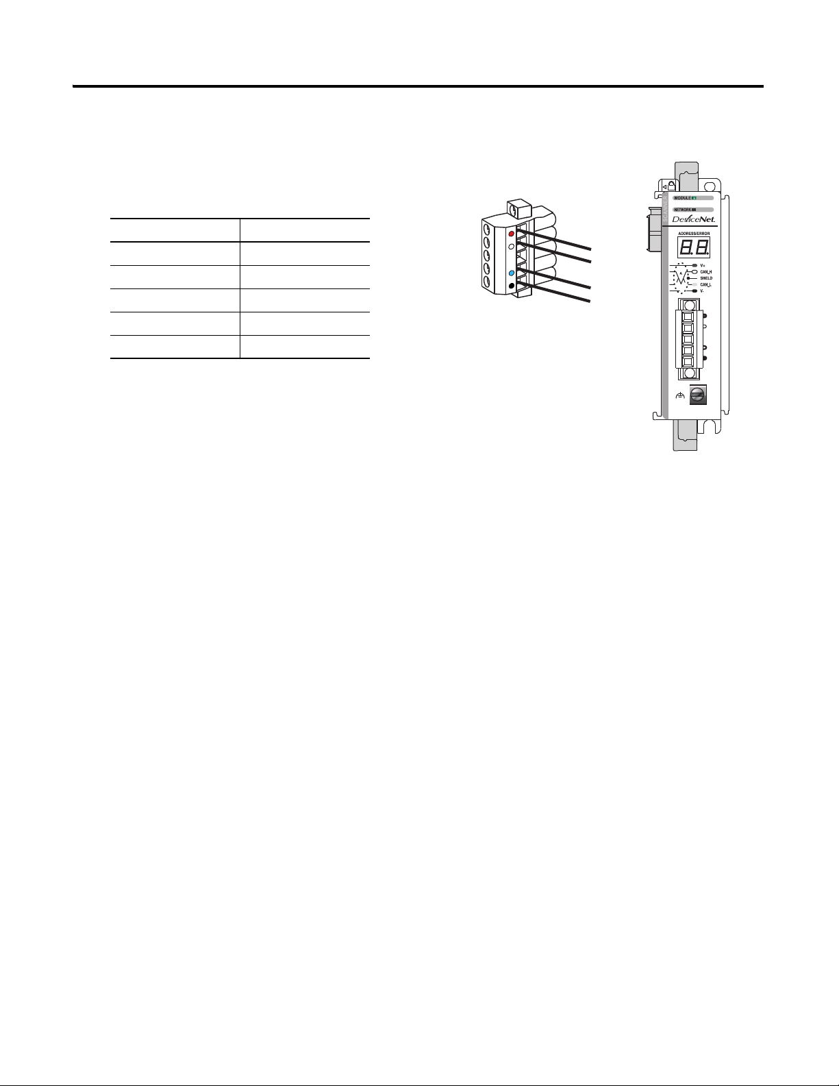
1. Connect a DeviceNet cable to the
removable connector.
2. Connect the removable connector to the
module.
Connect To
Red V+
White CAN High
Bare Shield
Blue CAN Low
Black V-
1769-SDN module
24 Publication IASIMP-QS001C-EN-P - October 2009
Page 25
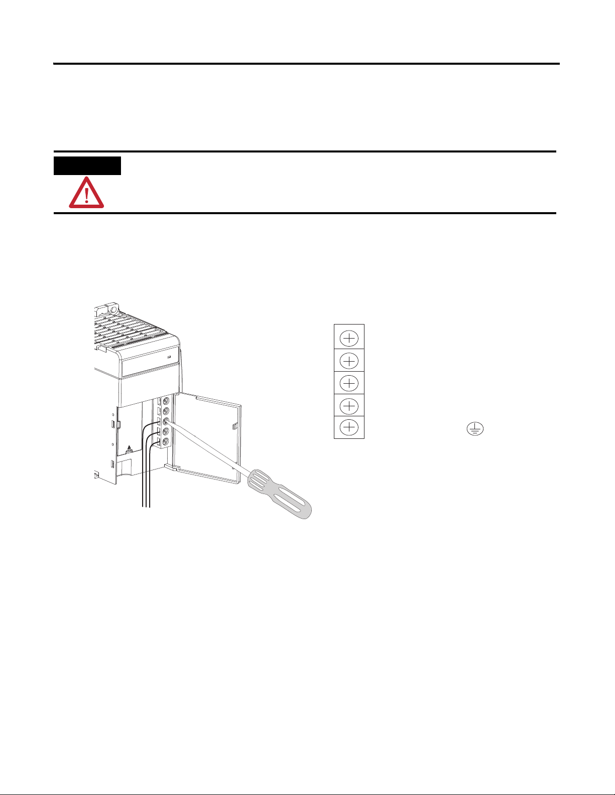
Wire Power
PWR OUT +24V DC
PWR OUT COM
120/240V AC
V AC COM
CHASSIS GROUND
1. Insert the 120/240V AC, V AC COM, and Chassis Ground wires and tighten the
terminal screws.
2. Turn on incoming power.
WARNING
Verify that all incoming power is turned off before wiring power.
Terminal Wiring Diagram
1769-PA2 power supply
Prepare the CompactLogix Hardware Chapter 1
Publication IASIMP-QS001C-EN-P - October 2009 25
Page 26

Chapter 1 Prepare the CompactLogix Hardware
Additional Resources
Resource Description
1769-L32E and 1769-L35E CompactLogix
Controller Installation Instructions, publication
1769-IN020
1769-L32C and 1769-L35CR CompactLogix
Controller Installation Instructions. publication
1769-IN070
1769-L31 CompactLogix Controller Installation
Instructions, publication 1769-IN069
1769-SDN Compact I/O DeviceNet Scanner
Module Installation Instructions, publication
1769-IN060
Compact 1769 Expansion I/O Power Supplies
Installation Instructions, publication
1769-IN028
Provides details about assembling and mounting the controller and upgrading firmware
as well as controller technical specifications.
Provides details about assembling and mounting the controller and upgrading firmware
as well as controller technical specifications.
Provides details about assembling and mounting the controller and upgrading firmware
as well as controller technical specifications.
Provides information about installing the 1769-SDN module and technical
specifications.
Provides details on power considerations, master control relay, safety circuits,
grounding, power dissipation, input power requirements, and technical specifications.
26 Publication IASIMP-QS001C-EN-P - October 2009
Page 27

Chapter
Prepare the Computer
In this chapter, you configure network communication on your computer and install the
necessary programming and configuration software.
Before You Begin
• Verify that your computer meets the software’s system requirements for your edition of RSLogix 5000
programming software.
• If using a ControlNet network (option 2), install a 1784-PCIC or 1784-PCICS ControlNet
communication card on the computer.
2
What You Need
• RSLinx Classic software, version 2.54 or later (packaged with RSLogix 5000 programming software).
• RSLogix 5000 programming software (see the Preface for version and edition information)
• RSNetWorx for ControlNet software for the ControlNet network
• RSNetWorx for DeviceNet software for the DeviceNet network
• ControlFlash software (packaged with RSLogix5000 programming software)
• BOOTP/DHCP server utility (packaged with RSLogix 5000 programming software).
• A Network Interface Card (NIC) and its associated Windows driver installed (the NIC and driver are
standard on most computers).
• An Ethernet Address (MAC) for each device. You recorded these addresses in the Network Worksheet
on the back cover.
• A planned IP Address for each device. If you are using an isolated network, determine a numbering
convention for your IP addresses. Record these addresses on the Network Worksheet inside the back
cover.
27Publication IASIMP-QS001C-EN-P - October 2009 27
Page 28
Chapter 2 Prepare the Computer
Terminology
Install RSLogix
Programming
Software
Configure a Serial
Driver
Configure the
EtherNet/IP
Driver in RSLinx
Install Additional
Software
Load Firmware
Optional
(Depending on your system.)
page 29
page 38
page 44
page 40
page 42
page 36
page 31
Set the IP
Address for
the Computer
Complete these steps.
28 Publication IASIMP-QS001C-EN-P - October 2009
Page 29
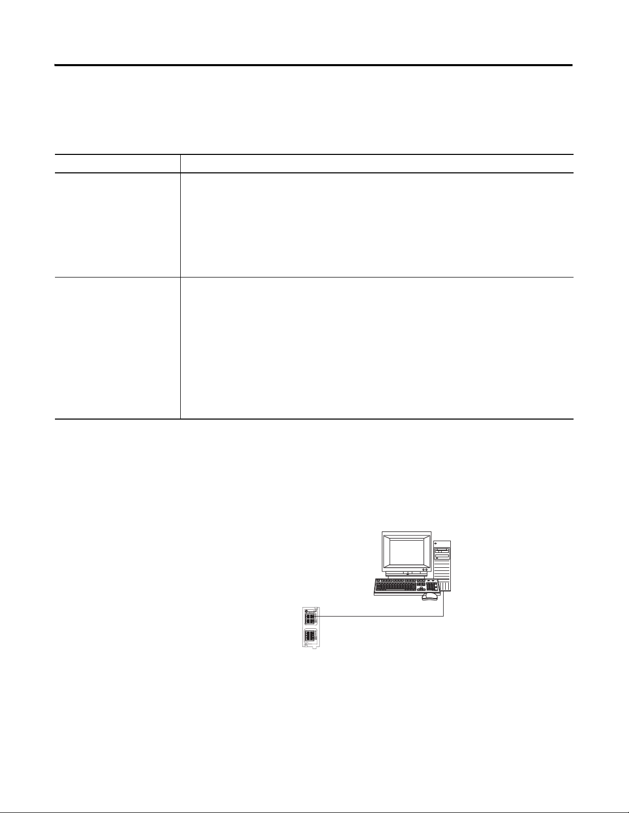
Prepare the Computer Chapter 2
Connect the Ethernet port of the computer to
the Ethernet switch.
Stratix 6000 Switch
Computer with
standard Ethernet port.
Terminology
Ethernet networks use these types of addresses.
Term Definition
Ethernet Address Each Ethernet device has a unique Ethernet address (sometimes called a MAC address). The
address appears as twelve digits separated by colons (for example, xx:xx:xx:xx:xx:xx). It is
usually on a label on the device itself.
Each digit is a number in hexadecimal (0 to 9 or A through F). No other device in the world will
have the same address, and it can not be changed.
You use the Ethernet address to identify a device so you can assign it an IP address.
IP Address In addition to the Ethernet address, an IP address identifies a node on an Ethernet network.
The IP address can be manually set. or you can use special software to automatically assign it.
An IP Address consists of four decimal integers separated by periods (xxx.xxx.xxx.xxx). Each xxx
is a decimal value from 0…255. For example, an IP Address could be 192.168.1.092 The
selection of IP Addresses is beyond the scope of this quick start, so please contact your
network administrator or use the ones provided in the examples.
Once you set an IP address for a device, you generally reference the device by its IP address.
The examples in this quick start use IP Addresses to define communication paths to the
devices.
Make Network Connections
Ethernet connection - Required for all options
Publication IASIMP-QS001C-EN-P - October 2009 29
Page 30
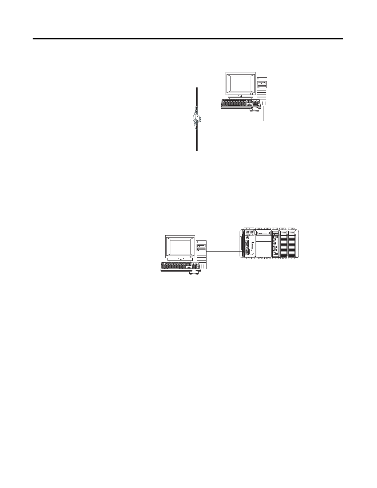
Chapter 2 Prepare the Computer
Connect a ControlNet tap to port A of the
ControlNet communication card in the
computer.
ControlNet Tap on
ControlNet Network
Computer with 1784-PCIC or
1784-PCICS communication
card.
You connected a 1756-CP3 cable to a COM port on the computer and to the CH0 port
on the controller in Chapter 1.
1756-CP3 serial cable to CH0 on 1769-L31.
ControlNet connection - 1769-L32C and 1769-L35CR controllers only
Serial connection - Required for all controllers
30 Publication IASIMP-QS001C-EN-P - October 2009
Page 31

Prepare the Computer Chapter 2
3. Accept the default
software products for
installation and click
Next.
Throughout the installation, click Next to use default RSLogix 5000 installation settings
except when indicated in the steps below.
1. Begin the RSLogix 5000
software installation.
2. Choose your language and
click Continue.
4. Enter your user name, organization, and
software serial number, then click Next.
Install RSLogix Programming Software
Required for all controllers
Publication IASIMP-QS001C-EN-P - October 2009 31
Page 32

Chapter 2 Prepare the Computer
7. Select your
activation type
and click Next.
This quick start uses
FactoryTalk
Activation software
to activate RSLogix
5000 software. For
more information,
see the FactoryTalk
Activation FAQ,
publication
Ftalk-FA017.
5. Accept the license agreement and
click Next.
8. Click Next to
install only the
latest version of
RSLogix 5000
software (version
18).
9. Verify that
RSLogix 5000
Tools and Files is
checked and click
Next.
6. Click Next to install the program
files to the default directory.
32 Publication IASIMP-QS001C-EN-P - October 2009
Page 33

10. Click Next to
install the typical
firmware kits.
11. Click Next to install
typical RSLogix
Architect tools.
12. Click Next to install
the typical set of
EDS files and
RSLinx software.
Prepare the Computer Chapter 2
Publication IASIMP-QS001C-EN-P - October 2009 33
Page 34

Chapter 2 Prepare the Computer
13. Click Install to
complete the
installation.
The installation
dialog box displays
progress while the
software installs.
TIP
As the installation progresses, you may be prompted to complete additional set-up tasks depending on
your system configuration. Follow those prompts and enter information as indicated in the dialog boxes to
complete your installation.
After a few moments, the
FactoryTalk Installation Wizard
starts.
14. Click Next.
15. Enter the Serial number and
Product key from the
certification letter packaged with
your software.
16. Click Next.
34 Publication IASIMP-QS001C-EN-P - October 2009
Page 35

17. Select your host ID and click
Next.
The activation completes if the
computer is connected to the
Internet.
If Internet access is not
available, call Rockwell
Automation Technical Support
to complete your activation.
18. Click Finish to close the
Activation Wizard.
Prepare the Computer Chapter 2
Publication IASIMP-QS001C-EN-P - October 2009 35
Page 36
Chapter 2 Prepare the Computer
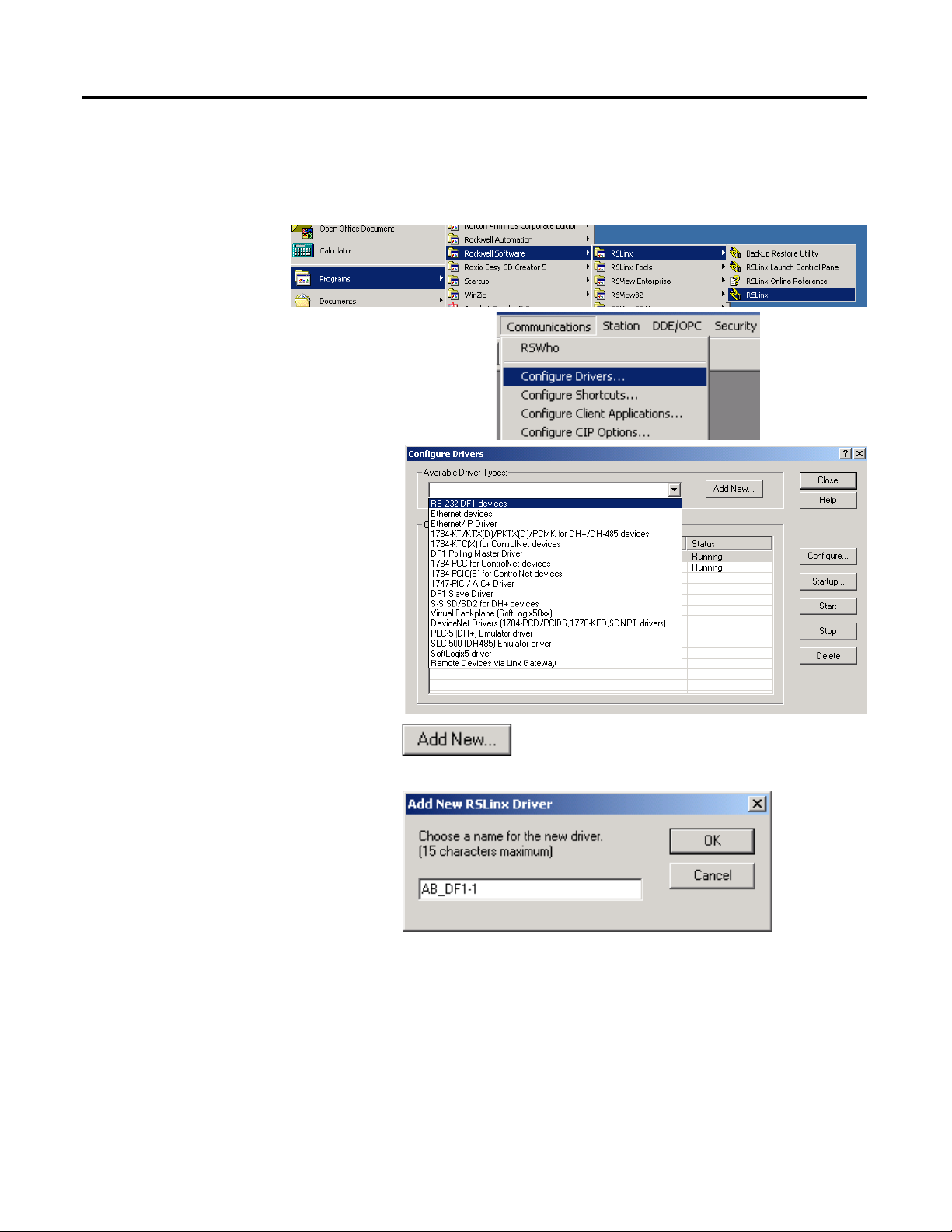
1. Launch RSLinx
software.
2. Under Communications, select Configure
Drivers.
3. Select RS-232 DF1 devices.
4. Click Add New.
5. Click OK to keep the default
name.
Configure a Serial Driver
Required for all controllers
36 Publication IASIMP-QS001C-EN-P - October 2009
Page 37

The Serial driver is added to the
Configured Drivers list.
10. Verify that the Status of the driver
is Running, and click Close.
11. Click the RSWho icon to view
the driver.
All of the configured, active drivers
display.
6. Select the Comm Port to which you
connected the 1756-CP3 cable.
7. For Device, select
Logix5550/CompactLogix.
8. Click Auto Configure.
9. Click OK.
Expand the serial driver to see
connected devices.
Prepare the Computer Chapter 2
Publication IASIMP-QS001C-EN-P - October 2009 37
Page 38

Chapter 2 Prepare the Computer
1. On your desktop, right-click My
Network Places and select
Properties.
2. Double-click the Local Area
Connection.
3. Click Properties.
4. On the General tab, select Internet
Protocol (TCP/IP) and click
Properties.
5. Select Use the following IP address
and enter an IP address and Subnet
mask for your computer using the
example shown or enter your own
address.
For more information about selecting
an IP Address, see page 81
.
6. Click OK.
7. Record the IP address and subnet mask in the Network Worksheet on the back cover.
8. Click OK.
Set the IP Address for the Computer
Required for all controllers, regardless of network choice
38 Publication IASIMP-QS001C-EN-P - October 2009
Page 39

9. Click the Support tab.
10. Verify that the IP Address and
Subnet Mask match what you entered
on the
Network Worksheet.
If these numbers do not match what
you entered, contact your network
administrator to verify that your IP
address is correct.
11. Close the Local Area Connection
Status dialog box.
Prepare the Computer Chapter 2
Publication IASIMP-QS001C-EN-P - October 2009 39
Page 40
Chapter 2 Prepare the Computer
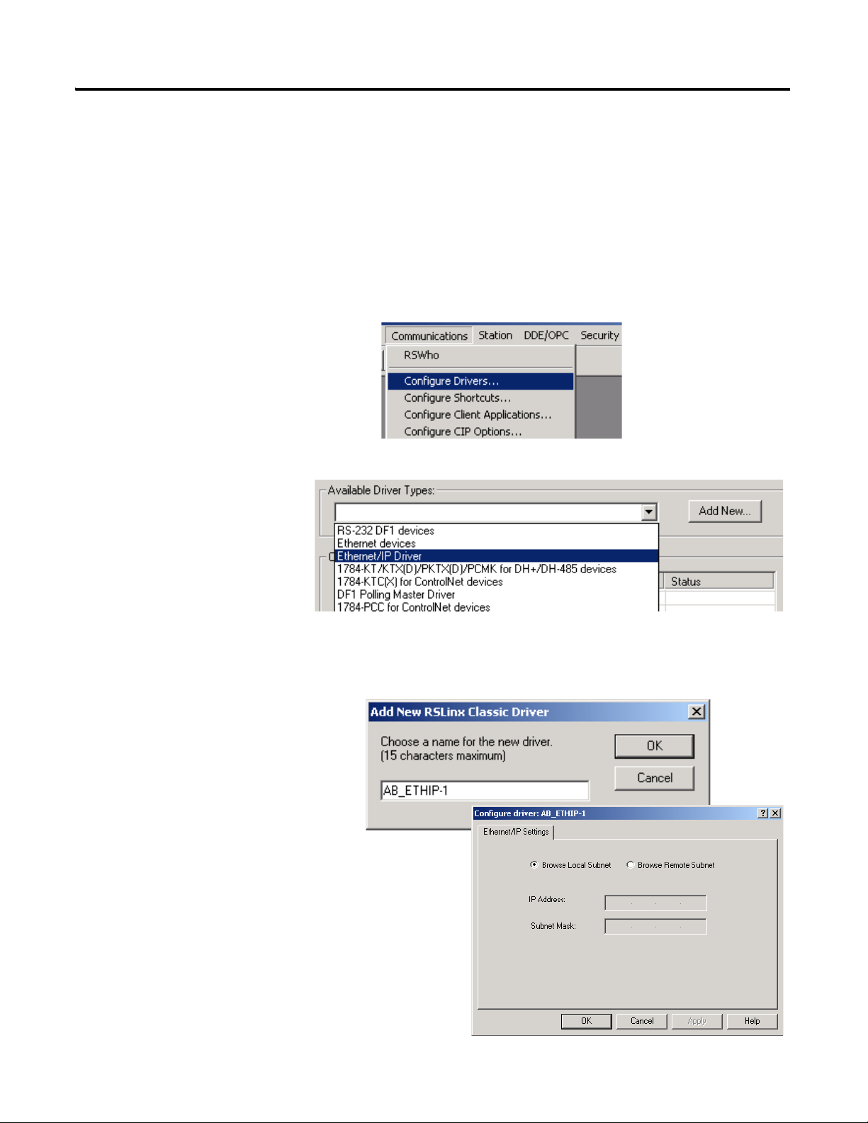
1. If RSLinx software is not open, launch RSLinx software.
2. From the Communications
menu, choose Configure
Drivers.
3. From the Available
Driver Types, select
Ethernet/IP Driver.
4. Click Add New.
5. Click OK to keep the default
name.
6. Click OK to Browse Local
Subnet.
Configure the EtherNet/IP Driver in RSLinx Software
Required for 1769-L32E,1767-L35E, and PanelView Plus
40 Publication IASIMP-QS001C-EN-P - October 2009
Page 41

Prepare the Computer Chapter 2
The EtherNet/IP driver is
added to the Configured
Drivers list.
7. Verify that the driver’s
Status is Running, and click
Close.
Publication IASIMP-QS001C-EN-P - October 2009 41
Page 42

Chapter 2 Prepare the Computer
TIP
1. Launch ControlFlash software.
2. Click Next.
3. Select the controller catalog
number and click Next.
Load Firmware
Required for all packaged controllers
This example shows how to load firmware using a serial connection. It is faster to load firmware
via an EtherNet/IP or ControlNet connection. For more information, see the installation
instructions for the controller as listed at the end of the chapter.
42 Publication IASIMP-QS001C-EN-P - October 2009
Page 43
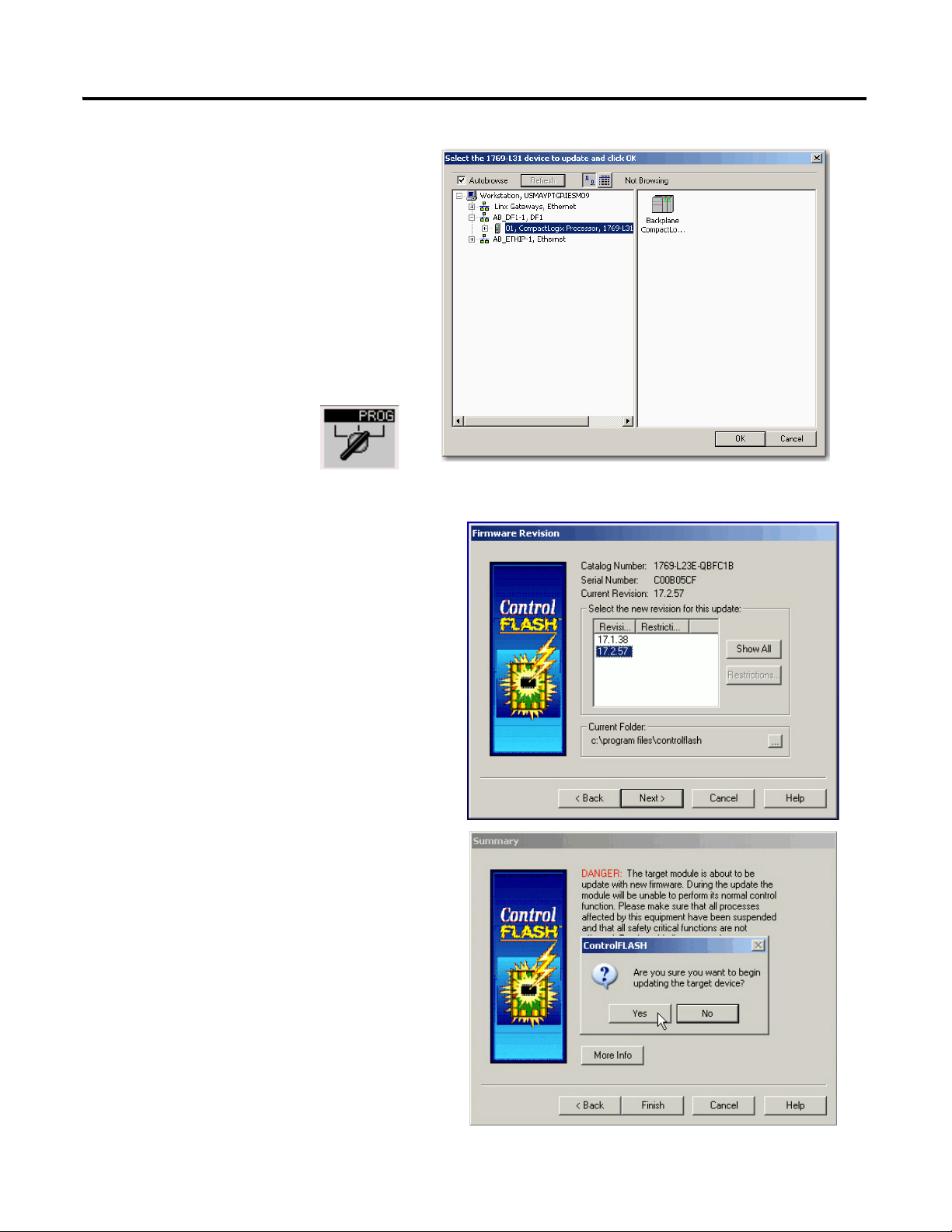
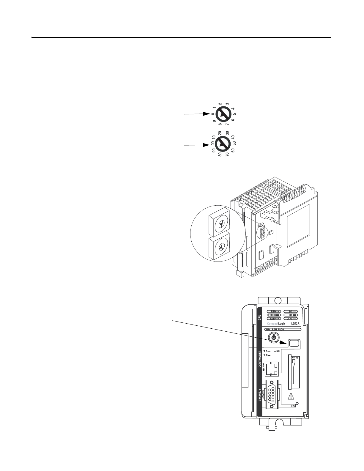
6. Move the keyswitch
on the controller to
PROG.
7. If the Current Revision matches the
revision of firmware you want, click
Cancel and skip to Chapter 3.
Otherwise, select the desired firmware
revision and click Next.
8. Click Finish to start the firmware
update.
4. Expand the AB_DF1-DFI driver,
and select your controller.
5. Click OK.
Prepare the Computer Chapter 2
Publication IASIMP-QS001C-EN-P - October 2009 43
Page 44

Chapter 2 Prepare the Computer
• If you are completing the PanelView Plus chapters in this quick start, install FactoryTalkView Machine
Edition software and RSLinx Enterprise software from the FactoryTalkView Machine Edition
package. This software must be installed before you install any additional software.
• If you are using a ControlNet network, install RSNetWorx for ControlNet software.
• If you are using a DeviceNet network, install RSNetWorx for DeviceNet software.
Install Additional Software
44 Publication IASIMP-QS001C-EN-P - October 2009
Page 45

Additional Resources
Resource Description
Prepare the Computer Chapter 2
1769-L32E and 1769-L35E CompactLogix
Controller Installation Instructions, publication
1769-IN020
1769-L32C and 1769-L35CR CompactLogix
Controller Installation Instructions. publication
1769-IN070
1769-L31 CompactLogix Controller Installation
Instructions, publication
FactoryTalk Activation FAQ, publication
1769-IN069
FTalk-FA017
ControlFlash Firmware Upgrade Kit, publication
1756-QS105
Provides details about assembling and mounting the controller and upgrading firmware
as well as controller technical specifications.
Provides details about how to assemble and mount the controller, how to upgrade
firmware, and controller technical specifications.
Provides details about assembling and mounting the controller and upgrading firmware
as well as controller technical specifications.
Provides answers to FactoryTalk Activation questions, including how the FactoryTalk
Activation differs from master disk activation.
Provides details regarding the installation of ControlFlash software and execution of
firmware upgrades.
Publication IASIMP-QS001C-EN-P - October 2009 45
Page 46

Chapter 2 Prepare the Computer
Notes:
46 Publication IASIMP-QS001C-EN-P - October 2009
Page 47

Chapter
3
Prepare the Distributed POINT I/O Hardware
In this chapter, you install the 1734 POINT I/O network adapter and the 1734 POINT I/O
modules.
Before You Begin
• Determine which of these network adapters to use:
– for an EtherNet/IP network (option 1), use the 1734-AENT adapter.
– for a ControlNet network (option 2), use the 1734-ACNR adapter.
– for a DeviceNet network (option 3), use the 1734-ADN adapter.
• Select the appropriate mounting base for I/O modules:
– if you use a 1734-IT2I module, then use the 1734-TBCJC.
– for all other I/O modules use the 1734-TB or 1734-TBS.
What You Need
• POINT I/O adapter: 1734-AENT, 1734-ACNR, and/or 1734-ADN
• POINT I/O mounting bases: 1734-TB or 1734-TBS, and 1734-TBCJC
• A digital-output POINT I/O module: The examples use a 1734-OB4E, however, other
POINT I/O modules can also be used, but are not required
• Power supply: 1794-PS3 or 1794-PS13
47Publication IASIMP-QS001C-EN-P - October 2009 47
Page 48

Chapter 3 Prepare the Distributed POINT I/O Hardware
Mount and Connect
the Network
Adapter
Mount the POINT
I/O Modules
Mount and Wire the
POINT I/O Power
Supply
Wire the Adapter
and I/O Modules to
the Power Supply
page 49
page 53
page 52
page 51
Follow These Steps
If you have a POINT I/O system, complete these steps.
48 Publication IASIMP-QS001C-EN-P - October 2009
Page 49

Mount and Connect the Network Adapter
1. Locate the Ethernet address (MAC), found
next to the label. Record the Ethernet address
(MAC) for the POINT I/O adapter on the
Network Worksheet
.
This address is used to set the IP address later
in the quick start.
2. Set the address to a value greater than or
equal to 256.
This example uses 999.
3. Remove the safety end cap.
4. Press the adapter onto the DIN rail.
5. Insert an Ethernet cable.
Go to Mount the POINT I/O Modules
.
00:00:BC:21:44:8A
Ethernet Address
Example Address
1. Remove the safety end cap.
2. Press the adapter onto the DIN rail.
3. Set the node address.
This example uses node 02.
4. Connect a ControlNet tap to the A port.
Go to Mount the POINT I/O Modules
.
EtherNet/IP 1734-AENT adapter
Prepare the Distributed POINT I/O Hardware Chapter 3
ControlNet 1734-ACNR adapter
Publication IASIMP-QS001C-EN-P - October 2009 49
Page 50

Chapter 3 Prepare the Distributed POINT I/O Hardware
1. Remove the safety end cap.
2. Press the adapter onto the DIN rail.
3. Set the node address.
This example uses node 02.
4. Connect the DeviceNet cable to the
removable connector.
5. Connect the removable connector to the
adapter.
Go to Mount the POINT I/O Modules
.
Connect To
Red V+
White CAN High
Bare Shield
Blue CAN Low
Black V-
DeviceNet Connector and Port
DeviceNet 1734-ADN adapter
50 Publication IASIMP-QS001C-EN-P - October 2009
Page 51
Mount the POINT I/O Modules
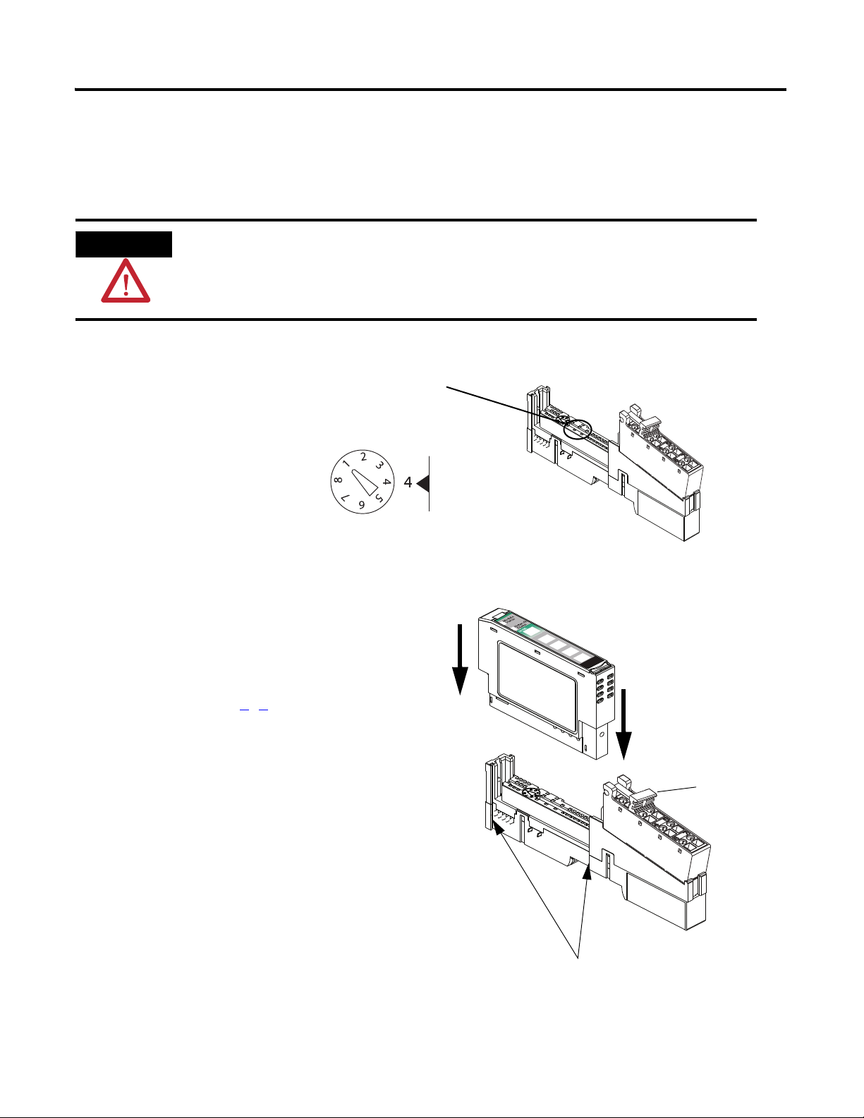
1. Using a small, flathead screwdriver, rotate the
keyswitch to match the figure on the I/O
module.
2. Press the module into the wiring base.
3. Snap the handle up.
4. Complete steps 1
–3 with all POINT I/O
modules.
5. Slide the first module and wiring base
assembly along the adapter and press it
onto the DIN rail.
6. Repeat with all of the I/O assemblies.
Handle
Tongue-and-groove Slots
ATTENTION
The 1734-IT2I module must be mounted in the 1734-TBCJC wiring base. All other modules can be
mounted in either of the 1734-TB or 1734-TBS wiring bases.
Figure on Module
Wiring Base
Module
All controllers, POINT I/O modules, and wiring bases
Prepare the Distributed POINT I/O Hardware Chapter 3
Publication IASIMP-QS001C-EN-P - October 2009 51
Page 52
Chapter 3 Prepare the Distributed POINT I/O Hardware
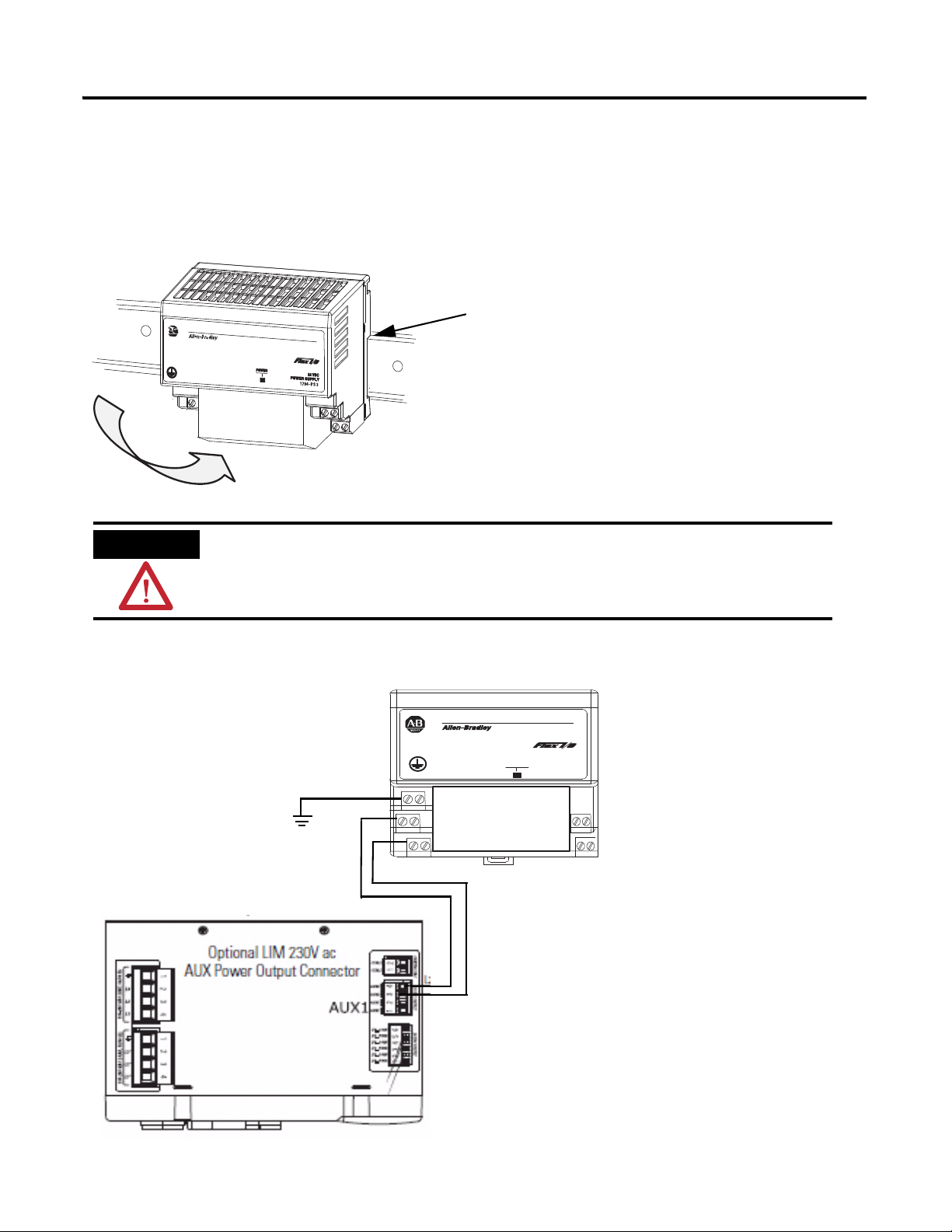
1. Hook the upper-lip of the DIN rail latch onto the
DIN rail.
2. Press the module onto the DIN rail.
3. Connect the
120/230V AC
power, 120/230V
AC common and
AC Ground wires.
WARNING
Verify that all incoming power is turned off before wiring power.
Upper-lip of DIN rail latch.
r
ewo
P
CD
V42
YLPPUS REWO
P
3S
P-4971
V42
MO
C
GR
L2/N
L1
L2
L1
Top View
Mount and Wire the POINT I/O Power Supply
1794-PS3 or 1794-PS13 power supplies
52 Publication IASIMP-QS001C-EN-P - October 2009
Page 53

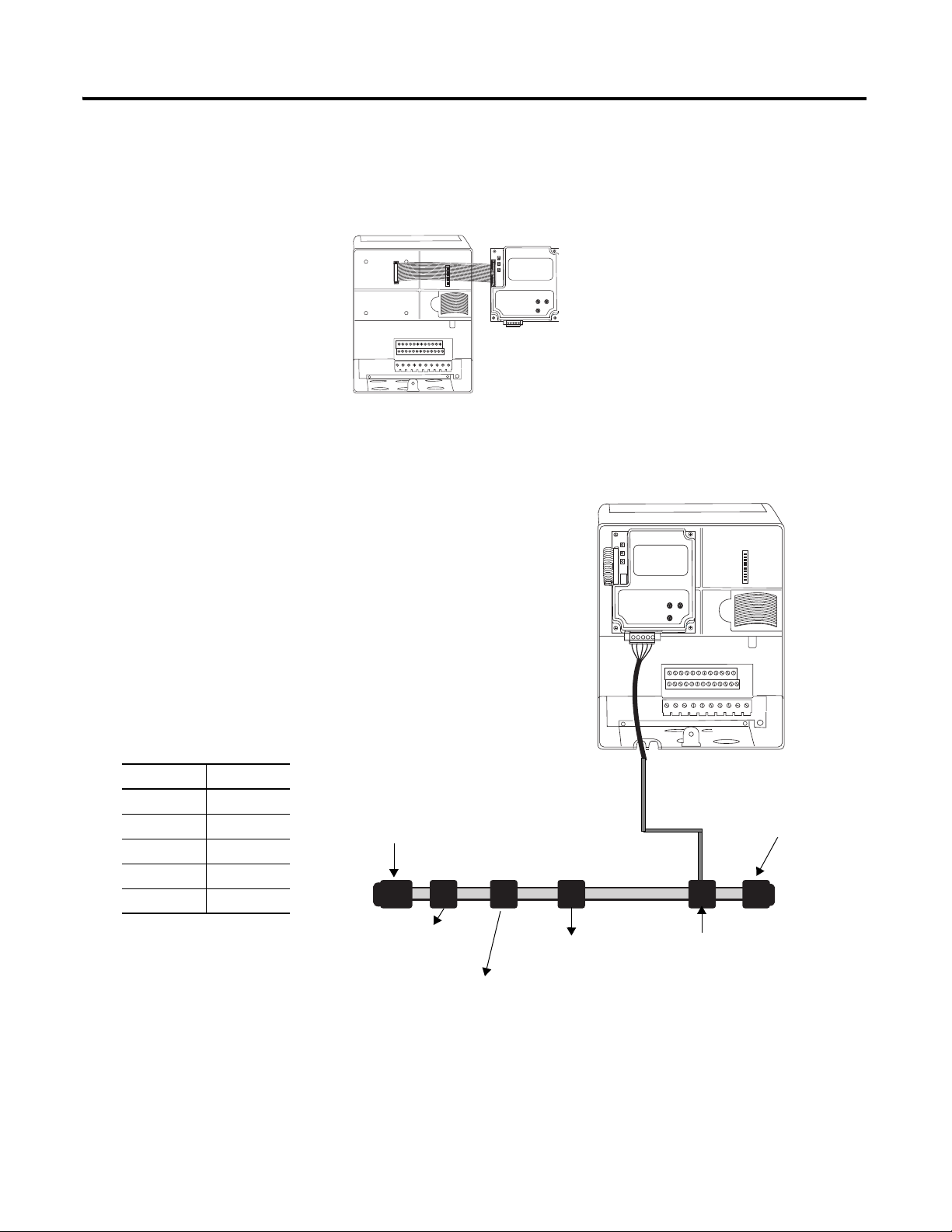
Prepare the Distributed POINT I/O Hardware Chapter 3
Common
Power
1. Connect the 12/24V DC
common and 12/24V DC
power wires from the power
supply to the adapter.
2. Refer to the individual POINT
I/O installation instructions for
wiring the I/O modules.
3. Turn on incoming power.
Wire the Adapter and I/O Modules to the Power Supply
POINT I/O adapter, I/O modules, and power supply
Additional Resources
Resource Description
Point I/O Ethernet Adapter Installation
Instructions, publication 1734-IN590
1734 Point I/O ControlNet Adapter Installation
Instructions, publication 1734-IN582
Point I/O DeviceNet Adapter Installation
Instructions, publication 1734-IN026
POINT I/O Wiring Base Assembly Installation
Instructions, publication 1734-IN511
Cold Junction Compensated Terminal Block
Installation Instructions, publication
1734-IN583
Point I/O Protected Output Module Installation
Instructions, publication 1734-IN056
FLEX I/O DC Power Supply Modules Installation
Instructions, publication 1794-IN069
Provides details regarding installation of the adapter and technical specifications.
Provides details regarding installation of the adapter and technical specifications.
Provides details regarding installation of the adapter and technical specifications.
Provides details regarding installation of the POINT I/O wiring base.
Provides details regarding installation of the Cold Junction Compensated Terminal
Block wiring base.
Provides details about the installation and wiring of POINT I/O Protected Output
Modules.
Provides details about the installation and wiring of FLEX I/O power supplies.
Publication IASIMP-QS001C-EN-P - October 2009 53
Page 54

Chapter 3 Prepare the Distributed POINT I/O Hardware
Notes:
54 Publication IASIMP-QS001C-EN-P - October 2009
Page 55

Chapter
4
Prepare the PowerFlex 70 Drive
In this chapter, you mount and wire power to a PowerFlex 70 drive. You also configure your
communication adapter and make network connections.
Before You Begin
Determine which network and appropriate adapter to use on the PowerFlex 70 drive:
• For an EtherNet/IP network (option 1), use the 20-COMM-E module.
• For a ControlNet network (option 2), use the 20-COMM-C module.
• For a DeviceNet network (option 3), use the 20-COMM-D module.
What You Need
• PowerFlex 70 drive
• Communication adapter for use with the PowerFlex 70 drive: 20-COMM-E
(EtherNet/IP adapter), 20-COMM-C (ControlNet adapter), or 20-COMM-D
(DeviceNet adapter)
55Publication IASIMP-QS001C-EN-P - October 2009 55
Page 56

Chapter 4 Prepare the PowerFlex 70 Drive
Mount the
PowerFlex 70 Drive
Wire Power
Configure the
Communication
Adapter
Connect
Communication
Adapter to the
PowerFlex 70 Drive
page 57
page 59
page 58
page 57
Follow These Steps
If you have a PowerFlex 70 drive, complete these steps.
56 Publication IASIMP-QS001C-EN-P - October 2009
Page 57

Prepare the PowerFlex 70 Drive Chapter 4
1. Loosen the screw and remove the cover.
2. Loosen the screws and slide the metal plate out
of the drive.
3. Connect the 120/240V AC, V AC COM and
chassis ground wires to the terminal block.
4. Replace the metal plate and tighten the screws.
Connect To
120/240V AC
L1
R
V AC COM
L2
S
Chassis ground
PE
WARNING
Verify that all incoming power is
turned off before wiring power.
L1RL2SL3TBR1
+DC
BR2
BRKT1UT2VT3W
PE PE
195-265 VAC LINE, 50/60 Hz
L3
L2
L1
230 VAC SUPPLY
CTRL2
CTRL1
195-265 VAC LOAD, 50/60 Hz
L3'
L2'
L1'
CONTROL VAC
AUX2
AUX2
AUX1
AUX1
I/O_COM
I/O_PWR
I/O_COM
I/O_PWR
I/O_COM
I/O_PWR
24 VDC SUPPLY
1 2
1 2 3 4
1 2 3 4
1 2 3 4
1 2 3 4 5 6
AUX1
Optional LIM 240V
AC
3-Phase Load
Connector
Motor
fus
Top View
Mount the PowerFlex 70 Drive
For the purpose of this quick start, the PowerFlex 70 drive can be propped in a safe and
convenient location.
For mounting instructions, see the PowerFlex 70 Drive User Manual, publication
20A-UM001
.
Wire Power
Publication IASIMP-QS001C-EN-P - October 2009 57
Page 58

Chapter 4 Prepare the PowerFlex 70 Drive
HW Address 00:00:BC:21:D7:BE
2
1
0
9
8
3
4
5
6
7
2
1
0
9
8
3
4
5
6
7
Tens
Digit
Ones
Digit
A
B
4 Shown
2
1
0
9
8
3
4
5
6
7
2
1
0
9
8
3
4
5
6
7
Tens
Digit
Ones
Digit
13 Shown
PGM
500K
250K
125K
AUTO
AUTO Shown
Configure the Communication Adapter
Adapter Action Figure
EtherNet/IP
20-COMM-E
ControlNet
20-COMM-C
DeviceNet
20-COMM-D
The Ethernet address (MAC) is found on
the adapter’s label. Record the Ethernet
address (MAC) on the Network
Worksheet. This address is used to set
the IP address later in the quick start.
Set the adapter’s node address.
The quick start examples use node
number 4.
1. Set the adapter’s node address.
The quick start examples use node
number 13.
For example:
2. Set the adapter for autobaud.
58 Publication IASIMP-QS001C-EN-P - October 2009
Page 59
Prepare the PowerFlex 70 Drive Chapter 4
POINT I/O with
1734-ADN Adapter
KwikLink Sealed
Terminator
KwikLink Sealed
Terminator
KwikLink Sealed
Micro Connector
1606-XLDNET8
Power Supply
1769-SDN
DeviceNet Module
Connect Communication Adapter to the PowerFlex 70 Drive
20-COMM-D DeviceNet Adapter for DeviceNet System
1. Connect the flat-ribbon
cable between the adapter
and the PowerFlex 70
drive.
2. Fold the cable under
adapter without creasing
and secure adapter on
drive using the captive
screws.
3. Remove a knockout from
4. Wire the KwikLink QD
5. Connect the QD Micro
the bottom plate on the
drive and route the
DeviceNet network cable
through the hole.
Micro Cordset to the
20-COMM-D connector.
Connect To
Red V+
White CAN High
Bare Shield
Blue CAN Low
Black V-
Cordset to a KwikLink
sealed micro connector
on the DeviceNet
network.
6. Replace drive cover.
Publication IASIMP-QS001C-EN-P - October 2009 59
Page 60

Chapter 4 Prepare the PowerFlex 70 Drive
20-COMM-E EtherNet/IP Adapter for EtherNet/IP System
1. Connect the flat-ribbon
cable between the adapter
and the PowerFlex 70
drive.
2. Fold the cable under the
adapter without creasing
and secure the adapter on
the drive using the captive
screws.
3. Remove a knockout from
the bottom plate on the
drive route the Ethernet
cable through the hole.
4. Connect a CAT5
Ethernet cable between
the Ethernet adapter and
the Ethernet switch.
5. Replace drive cover.
60 Publication IASIMP-QS001C-EN-P - October 2009
Page 61

Additional Resources
Resource Description
Prepare the PowerFlex 70 Drive Chapter 4
PowerFlex 70 User Manual, publication
20A-UM001
PowerFlex 70 EtherNet/IP Adapter User
Manual, publication 20COMM-UM010
PowerFlex 70 ControlNet Adapter User Manual,
publication 20COMM-UM003
PowerFlex 70 DeviceNet Adapter User Manual,
publication 20COMM-UM002
Provides details on how to install, program, and edit parameters for the PowerFlex 70
drive.
Provides details on how to install, configure, and use the adapter.
Provides details on how to install, configure, and use the adapter.
Provides details on how to install, configure, and use the adapter.
Publication IASIMP-QS001C-EN-P - October 2009 61
Page 62

Chapter 4 Prepare the PowerFlex 70 Drive
Notes:
62 Publication IASIMP-QS001C-EN-P - October 2009
Page 63

Chapter
5
Prepare the PowerFlex 40 Drive
In this chapter, you mount and wire power to a PowerFlex 40 drive. You also configure your
communication adapter and make network connections.
Before You Begin
Determine which of these networks and appropriate adapter to use:
• For an EtherNet/IP network (option 1), use the 22-COMM-E.
• For a ControlNet network (option 2), use the 22-COMM-C.
• For a DeviceNet network (option 3), use the 22-COMM-D.
What You Need
• PowerFlex 40 drive
• Communication adapter for use with the PowerFlex 40 drive: 22-COMM-E
(EtherNet/IP adapter), 22-COMM-C (ControlNet adapter) or 22-COMM-D
(DeviceNet adapter)
• Communication adapter cover for use with the PowerFlex 40
63Publication IASIMP-QS001C-EN-P - October 2009 63
Page 64

Chapter 5 Prepare the PowerFlex 40 Drive
Mount the
PowerFlex 40 Drive
Wire Power
Configure the
Communication
Adapter
Connect the
Communication
Adapter to the
PowerFlex 40 Drive
page 65
page 65
page 66
page 67
Follow These Steps
If you have a PowerFlex 40 drive, complete these steps.
64 Publication IASIMP-QS001C-EN-P - October 2009
Page 65

Prepare the PowerFlex 40 Drive Chapter 5
1. Remove the cover.
V/T2T/L3S/L2R/L1 U/T1 W/T3
BR+ BR-DC- DC+
2. Remove the terminal block cover to
access the power connections.
3. Insert the 120/240V AC, V AC COM
and chassis ground wires and tighten
the terminal screws.
Connect To
120/240V AC
R/L1
V AC COM
S/L2
Chassis ground
WARNING
Verify that all incoming power
is turned off before wiring
power.
Mount the PowerFlex 40 Drive
For mounting instructions, see the PowerFlex 40 Drive User Manual, publication
22B-UM001
.
Wire Power
Publication IASIMP-QS001C-EN-P - October 2009 65
Page 66

Chapter 5 Prepare the PowerFlex 40 Drive
HW Address 00:00:BC:21:D7:BE
2
1
0
9
8
3
4
5
6
7
2
1
0
9
8
3
4
5
6
7
Te n s D i g i t
Ones Di gi t
A
B
Node 3 shown
Node Switch
123456
0 000000
1 100000
2 010000
3 110000
4 001000
5 101000
6 011000
Rate Switch
78
125 Kbps 0 0
250 Kbps 1 0
500 Kbps 0 1
Autobaud 1 1
Node 3 Shown
Autobaud Shown
Configure the Communication Adapter
Adapter Action Figure
EtherNet/IP
22-COMM-E
ControlNet
22-COMM-C
DeviceNet
22-COMM-D
The Ethernet address (MAC) is found on
the adapter’s label. Record the Ethernet
address (MAC) on the Network
Worksheet. This address is used to set
the IP address.
Set the adapter’s node address.
This example uses node number 3.
Important: The front side of the adapter
(shown here) faces down when it is
installed in the drive. So, in the installed
position, port A is to the right of port B.
1. Set the adapter’s node address.
For example:
NODE
3
5
This example uses node number 3.
2. Set the rate to Autobaud.
66 Publication IASIMP-QS001C-EN-P - October 2009
5
3
Up = 1 =
Dow n = 0 =
Page 67

Prepare the PowerFlex 40 Drive Chapter 5
1. If you are using a DeviceNet network, remove the terminal block connector from the
22-COMM-D adapter and connect the DeviceNet cable to the terminal block.
2. For all adapters, attach the extending screws.
Connect To
Red V+
White CAN High
Bare Shield
Blue CAN Low
Black V-
0.8…1 Nm (7…9 lb•in)
Connect the Communication Adapter to the PowerFlex 40 Drive
22-COMM-E, 22-COMM-C, 22-COMM-D adapter
Publication IASIMP-QS001C-EN-P - October 2009 67
Page 68

Chapter 5 Prepare the PowerFlex 40 Drive
0.5-0.6 N-m
(4-5 lb.-in.)
4. Place the adapter cover on the PowerFlex.
5. Tighten the screws.
6. For all networks, connect the network cable to the
adapter.
7. Apply power to the PowerFlex 40 drive.
Important: The front side of the ControlNet adapter faces down
when it is installed in the drive. So, in the installed position, port
A is to the right of port B.
3. Snap the adapter into the cover and connect the cable from the adapter to the
PowerFlex 40 drive.
0.5…0.6 Nm
(4…5 lb-in)
68 Publication IASIMP-QS001C-EN-P - October 2009
Page 69

Additional Resources
Resource Description
Prepare the PowerFlex 40 Drive Chapter 5
PowerFlex 40 Adjustable Frequency AC Drive
User Manual, publication 22B-UM001
PowerFlex 40 EtherNet/IP Adapter User
Manual, publication 22COMM-UM004
PowerFlex 40 ControlNet Adapter User Manual,
publication 22COMM-UM006
PowerFlex 40 DeviceNet Adapter User Manual,
publication 22COMM-UM003
Provides details on how to install, program, and edit parameters for the PowerFlex 40
drive.
Provides details on how to install, configure, and use the adapter.
Provides details on how to install, configure, and use the adapter.
Provides details on how to install, configure, and use the adapter.
Publication IASIMP-QS001C-EN-P - October 2009 69
Page 70

Chapter 5 Prepare the PowerFlex 40 Drive
Notes:
70 Publication IASIMP-QS001C-EN-P - October 2009
Page 71

Chapter
6
Prepare the PanelView Plus Terminal
In this chapter, you mount and wire power to a PanelView Plus terminal. You also configure
network communication and make network connections.
Before You Begin
Determine which network connection to use: EtherNet/IP, ControlNet, or serial.
Regardless of which CompactLogix controller you use, you need to connect to the PanelView
Plus terminal via an EtherNet/IP network for initial configuration, via a cross-over cable or
an Ethernet switch.
What You Need
• PanelView Plus terminal
• For a ControlNet network (option 2), use a PanelView Plus ControlNet interface
module
• One power supply, either a 1794-PS3 or a 2711P-RSACDIN
• Ethernet cable and switch or Ethernet cross-over cable
• For a serial connection (option 3), 2706-NC13 cable
71Publication IASIMP-QS001C-EN-P - October 2009 71
Page 72

Chapter 6 Prepare the PanelView Plus Terminal
EtherNet/IP ControlNet Serial
Install the
ControlNet
Interface Module
page 73
Mount the
PanelView Plus
page 73
Wire the
PanelView Plus
Terminal to the
page 74
Make Network
Connections
page 75
Mount the
PanelView Plus
page 73
Wire the
PanelView Plus
Terminal to the
page 74
Make Network
Connections
page 75
1769-L31
controller
page 76
Mount the
PanelView Plus
page 73
Wire the
PanelView Plus
Terminal to the
page 74
Make Network
Connections
page 75
Follow These Steps
If you have a PanelView Plus terminal, complete these steps for your network.
72 Publication IASIMP-QS001C-EN-P - October 2009
Page 73

Install the ControlNet Interface Module
1. Remove the label covering the communication
module connector on the logic module.
2. Position the communication module over the logic module
so the connectors align.
3. Push down on the communication module until connectors
are firmly seated.
4. Tighten the 4 screws that secure the communication module
to the logic module.
Logic Module
Communication Module
ControlNet only
Prepare the PanelView Plus Terminal Chapter 6
Mount the PanelView Plus Terminal
2711P-K10C4D1 terminal and all controllers
For the purpose of this quick start, the PanelView Plus can be propped on a desktop.
For mounting instructions, see the PanelView Plus Terminals User Manual
2711P-UM001.
, publication
Publication IASIMP-QS001C-EN-P - October 2009 73
Page 74

Chapter 6 Prepare the PanelView Plus Terminal
rewoP
CD V42
YLPPUS REWOP
3SP-4971
V42
MOC
+
–
1. Remove the terminal block from the PanelView Plus terminal.
WARNING
Verify that all incoming power is turned off before wiring power.
Common
Power
2. Connect the 12/24V DC common and
12/24V DC power wires from the power
supply to the terminal block,
- (common) and + (power).
3. Connect the terminal block to the
PanelView Plus.
4. Turn on incoming power.
Wire the PanelView Plus Terminal to the Power Supply
74 Publication IASIMP-QS001C-EN-P - October 2009
Page 75

Make Network Connections
Connect an Ethernet cable.
Connect the other end of the cable to an
Ethernet switch.
Connect a ControlNet cable to port A.
Connect the tap to the ControlNet network.
Required for all controllers
Prepare the PanelView Plus Terminal Chapter 6
1769-L32C or 1769-L35CR controllers
Publication IASIMP-QS001C-EN-P - October 2009 75
Page 76

Chapter 6 Prepare the PanelView Plus Terminal
Connect the 2706-NC13 cable
to the serial port. Connect the
other end of cable to the
Channel 1 port on the 1769-L31
controller.
1756-CP3 Serial Cable to
Channel 0 Port
1769-L31 controller
76 Publication IASIMP-QS001C-EN-P - October 2009
Page 77

Assign an IP Address
Networks and Communications
Network Connections
Network Adapters
Built-in Ethernet Controller
Required for all Ethernet/IP
System
1. Apply power to the
PanelView terminal.
2. On the initial PanelView
configuration screen,
select Terminal Settings
[F4].
3. Navigate to
Built-in Ethernet
Controller by selecting
the path shown.
Diagnostics Setup
Display
File Management
Font Linking
Input Devices
Networks and Communications
Print Setup
Startup Options
System Event Log
System Information
Time/Date/Regional Settings
Prepare the PanelView Plus Terminal Chapter 6
4. Select IP Address [F2].
Publication IASIMP-QS001C-EN-P - October 2009 77
Page 78

Chapter 6 Prepare the PanelView Plus Terminal
5. Select IP Address [F1].
a. Enter an IP address in
the input panel.
b. Press Enter.
c. Record IP address in
Appendix A.
For information on IP
addresses, see
Chapter 7.
6. Select Subnet Mask [F2].
a. Enter the subnet mask
you wrote on the
Worksheet.
Network
b. Press Enter.
7. Select OK [F7] to save
settings, then OK [F7]
again to acknowledge
reset message.
78 Publication IASIMP-QS001C-EN-P - October 2009
Page 79

8. Select Close [F8] until
you return to the initial
configuration screen.
9. Select Reset [F8] to reset
the terminal, then
Yes [F7] to confirm.
Prepare the PanelView Plus Terminal Chapter 6
Publication IASIMP-QS001C-EN-P - October 2009 79
Page 80

Chapter 6 Prepare the PanelView Plus Terminal
Additional Resources
Resource Description
PanelView Plus Terminals User Manual,
publication 2711P-UM001
Provides details on how to install, program, and edit parameters for the PowerFlex 70
drive.
80 Publication IASIMP-QS001C-EN-P - October 2009
Page 81

Configure the EtherNet/IP Network
In this chapter, you assign IP addresses to devices on an EtherNet/IP network.
Before You Begin
• Prepare the computer, see Chapter 2
• Install all hardware, see Chapters 1–6
If you connect all of the devices, including the computer, through an Ethernet switch,
you can create an isolated network. This chapter assumes you are using an isolated
network. If you are not, contact your network administrator to obtain IP addresses.
• Verify that power is applied to all devices.
Chapter
7
What You Need
• The computer needs a Network Interface Card (NIC) and its associated Windows driver
installed (the NIC and driver are standard on most computers).
• BOOTP/DHCP utility, such as the one that ships on the RSLogix 5000 programming
software CD.
• An Ethernet Address (MAC) for each device. You recorded these addresses in the
Network Worksheet
• An IP Address for each device. If you are on an non-isolated network, obtain these
addressed from your network administrator. If you are on an isolated network,
determine a numbering convention for your IP addresses. Record these addresses in the
Network Worksheet on the backcover.
• You do not need to assign an IP address to the PanelView Plus terminal, it was already
assigned in Chapter 6
on the back cover.
.
81Publication IASIMP-QS001C-EN-P - October 2009 81
Page 82

Chapter 7 Configure the EtherNet/IP Network
Assign IP Addresses
to Devices
Browse the
EtherNet/IP
Network in RSLinx
page 83
page 85
Follow These Steps
If you have an EtherNet/IP network, complete these steps.
Terminology
Ethernet networks use these types of addresses:
Term Definition
Ethernet Address Each Ethernet device has a unique Ethernet address (sometimes called a MAC address). The
address appears as twelve digits separated by colons (for example, xx:xx:xx:xx:xx:xx). It is
usually on a label on the device itself.
Each digit is a number in hexadecimal (0 to 9 or A to F). No other device in the world will have
the same address, and it can not be changed.
You use the Ethernet address to identify a device so you can assign it an IP address.
IP Address In addition to the Ethernet address, an IP address identifies a node on an Ethernet network.
The IP address can be manually set. or you can use special software to automatically assign it.
An IP Address consists of four decimal integers separated by periods (xxx.xxx.xxx.xxx). Each xxx
is a decimal value from 0 to 255. For example, an IP Address could be 192.168.0.1. The
selection of IP Addresses is beyond the scope of this quick start, so please contact your
network administrator or use the ones provided in the examples.
Once you set an IP address for a device, you generally reference the device by its IP address.
The examples in this quick start use IP Addresses to define communication paths to the
devices.
82 Publication IASIMP-QS001C-EN-P - October 2009
Page 83

Assign IP Addresses to Devices
1. Launch the BOOTP/DHCP Server utility.
The BOOTP/DHCP Server utility is used to assign IP addresses to most
of the devices in this quick start.
2. From the Tools menu, choose Network
Settings.
3. Enter the Subnet Mask from the
Network Worksheet
.
4. Click OK.
The Request History displays all the devices on your network that need IP
addresses. The Ethernet address (MAC) corresponds with the addresses
recorded on Network Worksheet
.
TIP
Devices on the EtherNet/IP network broadcast requests for IP addresses until the IP addresses
have been assigned.
The procedure in this chapter uses the BOOTP Server packaged with RSLogix 5000 programming
software to assign IP addresses, however, any industry-standard BootP server will work.
This step assigns IP addresses to all of the devices in your system, except for the PanelView
Plus terminal. The IP address for the PanelView Plus terminal was assigned during
installation (see Chapter
6).
Configure the EtherNet/IP Network Chapter 7
Publication IASIMP-QS001C-EN-P - October 2009 83
Page 84
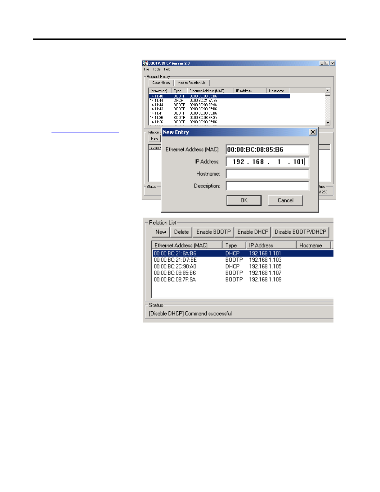
Chapter 7 Configure the EtherNet/IP Network
5. Double-click a request
from one of the devices.
6. Enter the corresponding
IP address that you
selected from the
Network Worksheet
.
If you are not using an
isolated network,
obtain these numbers
from your network
administrator.
7. Repeat steps 5
and 6 for
all devices, except the
PanelView Plus terminal
(the IP address for the
PanelView Plus terminal
was set in Chapter 6
).
If a device is power
cycled, it will not retain its
IP address unless you
disable BOOTP/DHCP.
8. Select the first device in the Relation List and click Disable BOOTP/DHCP.
[Disable BOOTP/DHCP] Command successful appears in the Status bar.
9. Repeat step 8 for all devices, except the PanelView Plus.
10. Close the BOOTP/DHCP Server utility.
If you are prompted to save changes, click No.
84 Publication IASIMP-QS001C-EN-P - October 2009
Page 85
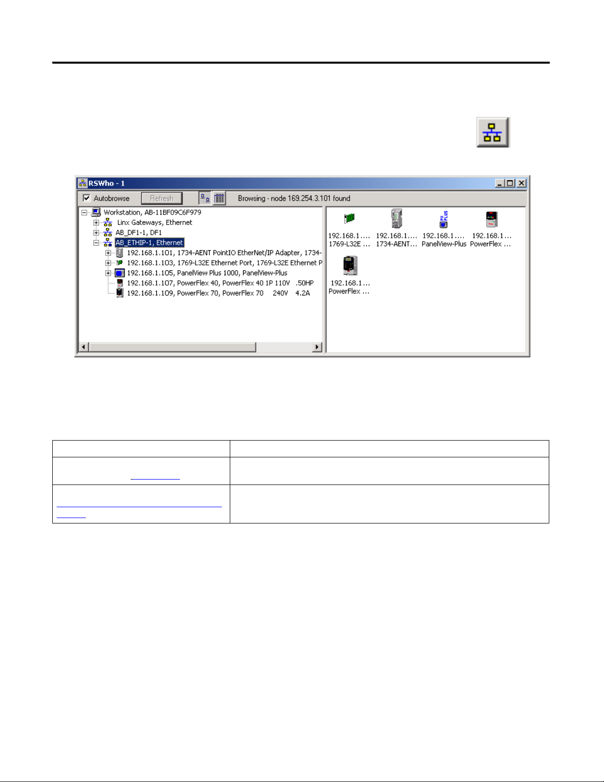
Browse the EtherNet/IP Network in RSLinx
Configure the EtherNet/IP Network Chapter 7
Additional Resources
Resource Description
EtherNet/IP Modules in Logix5000 Control
Systems, publication
Tech Note # E47839422 available at:
http://www.rockwellautomation.com/knowled
gebase/
ENET-UM001
Provides details regarding the installation, configuration, and operation of EtherNet/IP
modules.
Provides a description of a common Comms error dialog and its solution.
Publication IASIMP-QS001C-EN-P - October 2009 85
Page 86

Chapter 7 Configure the EtherNet/IP Network
Notes:
86 Publication IASIMP-QS001C-EN-P - October 2009
Page 87

Chapter
Configure the
ControlNet Driver in
RSLinx
page 88
8
Configure the ControlNet Driver
In this chapter, you configure the ControlNet driver for your computer so you can program
over a ControlNet network.
Before You Begin
• Prepare the computer, see Chapter 2.
• Install all hardware, see Chapters 1-6
• Connect the computer, controller and all other ControlNet devices to a ControlNet
network. This example uses BNC coaxial connectors to connect the taps and a
terminating resistor at each end.
• Verify that power is applied to all devices.
.
What You Need
• RSNetWorx for ControlNet
• A 1784-PCIC or 1784-PCICS card and associated driver installed on your computer
Follow These Steps
If you have a ControlNet network, complete this step.
87Publication IASIMP-QS001C-EN-P - October 2009 87
Page 88
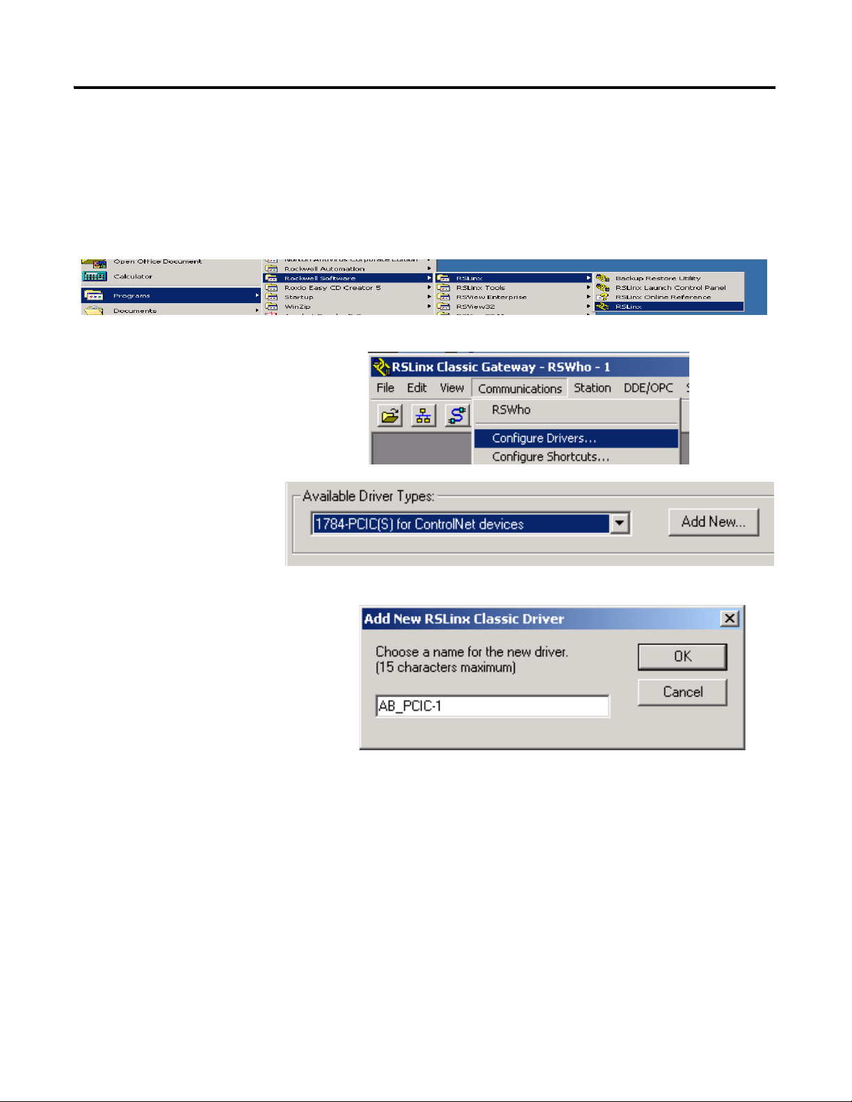
Chapter 8 Configure the ControlNet Driver
1. Launch RSLinx software.
2. From the
Communications menu,
choose Configure Drivers.
3. From the Available Driver
Types pull-down
menu, choose
1784-PCIC(S) for
ControlNet devices.
4. Click Add New.
5. Click OK to keep the default
name.
Configure the ControlNet Driver in RSLinx
RSLinx software
88 Publication IASIMP-QS001C-EN-P - October 2009
Page 89

6. Enter an available ControlNet
node address for the PCIC card.
This example uses node
addresses between 1 and 10
because it is a small ControlNet
Network.
7. Click OK.
The ControlNet driver is added to the Configured Drivers list.
8. Verify that the driver’s Status is Running, and click Close.
Configure the ControlNet Driver Chapter 8
Publication IASIMP-QS001C-EN-P - October 2009 89
Page 90
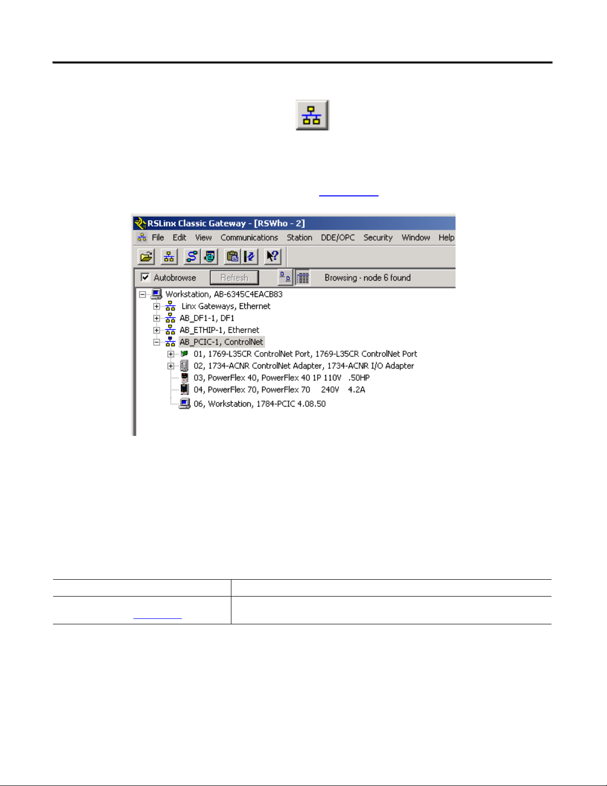
Chapter 8 Configure the ControlNet Driver
9. Click RSWho to view the driver.
10. Expand the driver to view the devices on your ControlNet network.
The PanelView Plus terminal does not appear because you have not set the
node address yet. The node address is set in Chapter 14
.
Additional Resources
Resource Description
ControlNet Modules in Logix5000 Control
Systems, publication CNET-UM001
Provides details regarding the installation, configuration, and operation of ControlNet
modules.
90 Publication IASIMP-QS001C-EN-P - October 2009
Page 91

Chapter
9
Configure the DeviceNet Network
In this chapter, you configure the DeviceNet node address for the 1769-SDN module. You
also create the RSNetWorx for DeviceNet file that stores network configuration.
Before You Begin
• Prepare the computer, see Chapter 2.
• Install all hardware, see Chapters 1
• Connect the 1769-SDN module, the 1734-ADN adapter and the PowerFlex drives to a
DeviceNet network.
This example uses KwikLink right-angle male cables with sealed micro connectors
connected to flat cable with terminator/resistors on each end.
• Verify that power is applied to all devices.
–6.
What You Need
• Power supply and tap for the DeviceNet network.
This example uses the 1606-XLDNET8 and a KwikLink power tap module.
• RSNetWorx for DeviceNet software.
91Publication IASIMP-QS001C-EN-P - October 2009 91
Page 92

Chapter 9 Configure the DeviceNet Network
Apply Power to the
DeviceNet Network
Set the 1769-SDN
Module’s Node
Address
Create a DeviceNet
Configuration File
page 93
page 94
page 96
Follow These Steps
If you have a DeviceNet network, complete these steps.
92 Publication IASIMP-QS001C-EN-P - October 2009
Page 93
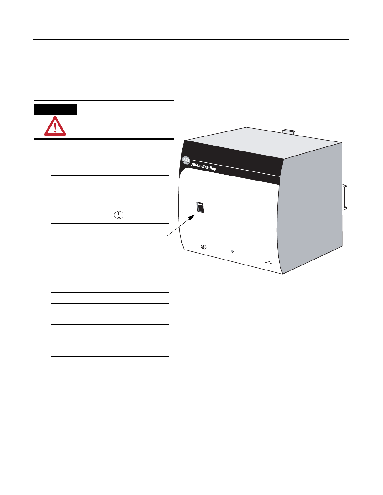
Apply Power to the DeviceNet Network
1. Connect incoming power to the
power supply.
2. Place the switch in the position that
matches your supply voltage.
3. Connect the DeviceNet power tap
to the power supply.
For this example, there is no need to connect the DC ok relay on the power supply to
anything.
4. If you have unused DeviceNet wires, make sure they do not come into contact with
the other wires.
5. Connect the DeviceNet power tap to the DeviceNet network.
6. Turn on incoming power.
WARNING
Verify that all incoming
power is turned off before
wiring power.
Connect To
V AC COM N (neutral)
120/240V AC L (line)
Ground
Connect To
Red +
White N/A
Shield N/A
Blue N/A
Black –
1606-XLDNET8 power supply
Configure the DeviceNet Network Chapter 9
AC 120V
AC 240V
Input
AC 100-120/200-240V
N L
Isolate power before disconnecting
DC ok
1606-XL
POWER SUPPLY
Output
200W Limited Power
DC 24V / 8A
+ –
DC ok
Publication IASIMP-QS001C-EN-P - October 2009 93
Page 94
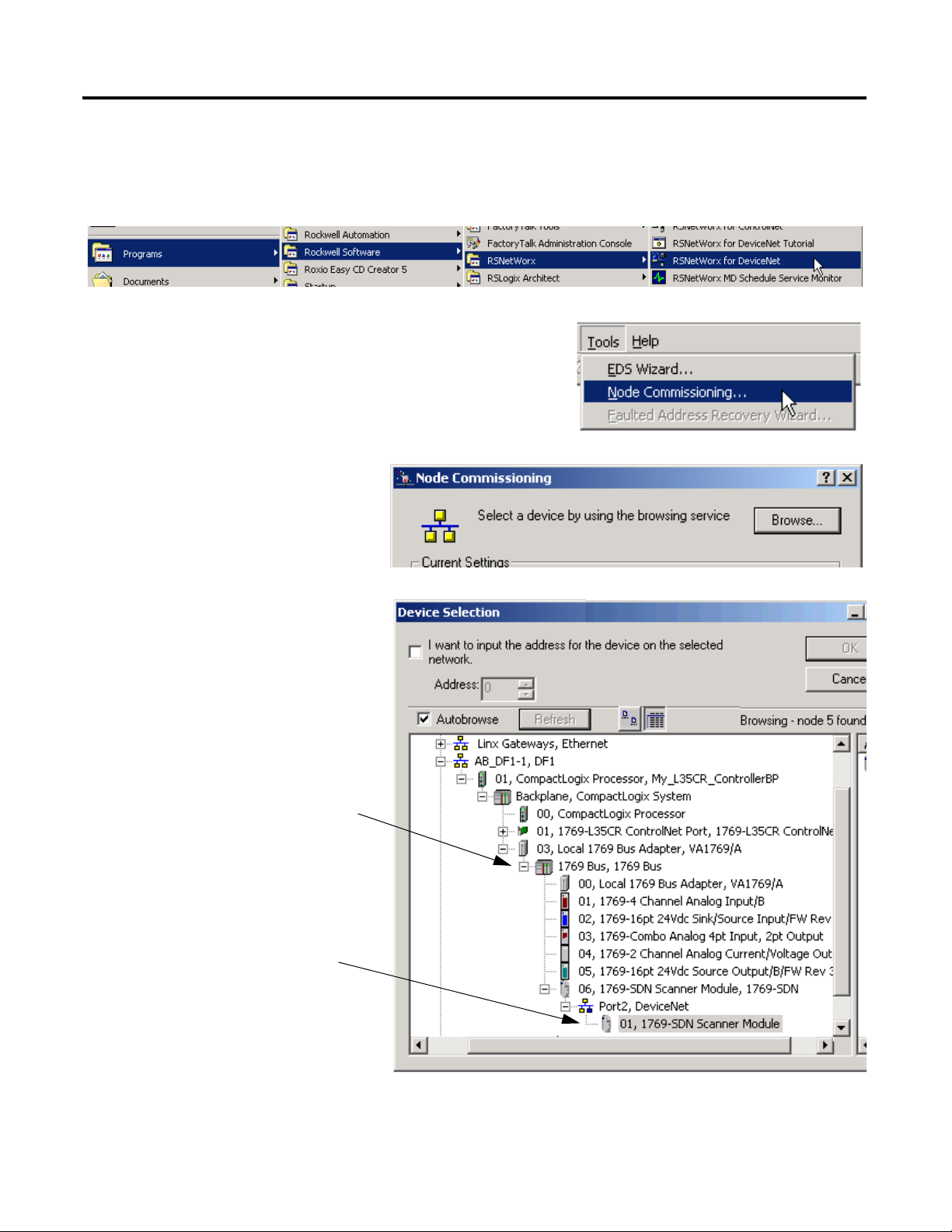
Chapter 9 Configure the DeviceNet Network
1. Launch RSNetWorx for DeviceNet software.
2. From the Too ls menu, choose Node
Commissioning.
3. Click Browse.
4. Under AB_DF1-1, expand
the CompactLogix Backplane
and the 1769 Bus.
5. Expand the 1769-SDN and
the DeviceNet Port, and select
the 1769-SDN.
6. Click OK.
Set the 1769-SDN Module’s Node Address
94 Publication IASIMP-QS001C-EN-P - October 2009
Page 95

The Node Commissioning
dialog is populated with the
1769-SDN module’s current
settings.
8. Select 1 for the node Address
of the 1769-SDN and click
Apply.
The Address is applied and is
confirmed in the Messages box.
9. Record the node address on the
Network Worksheet
.
10. Click Close.
7. If you receive a linking device
warning, click Yes.
Configure the DeviceNet Network Chapter 9
Publication IASIMP-QS001C-EN-P - October 2009 95
Page 96
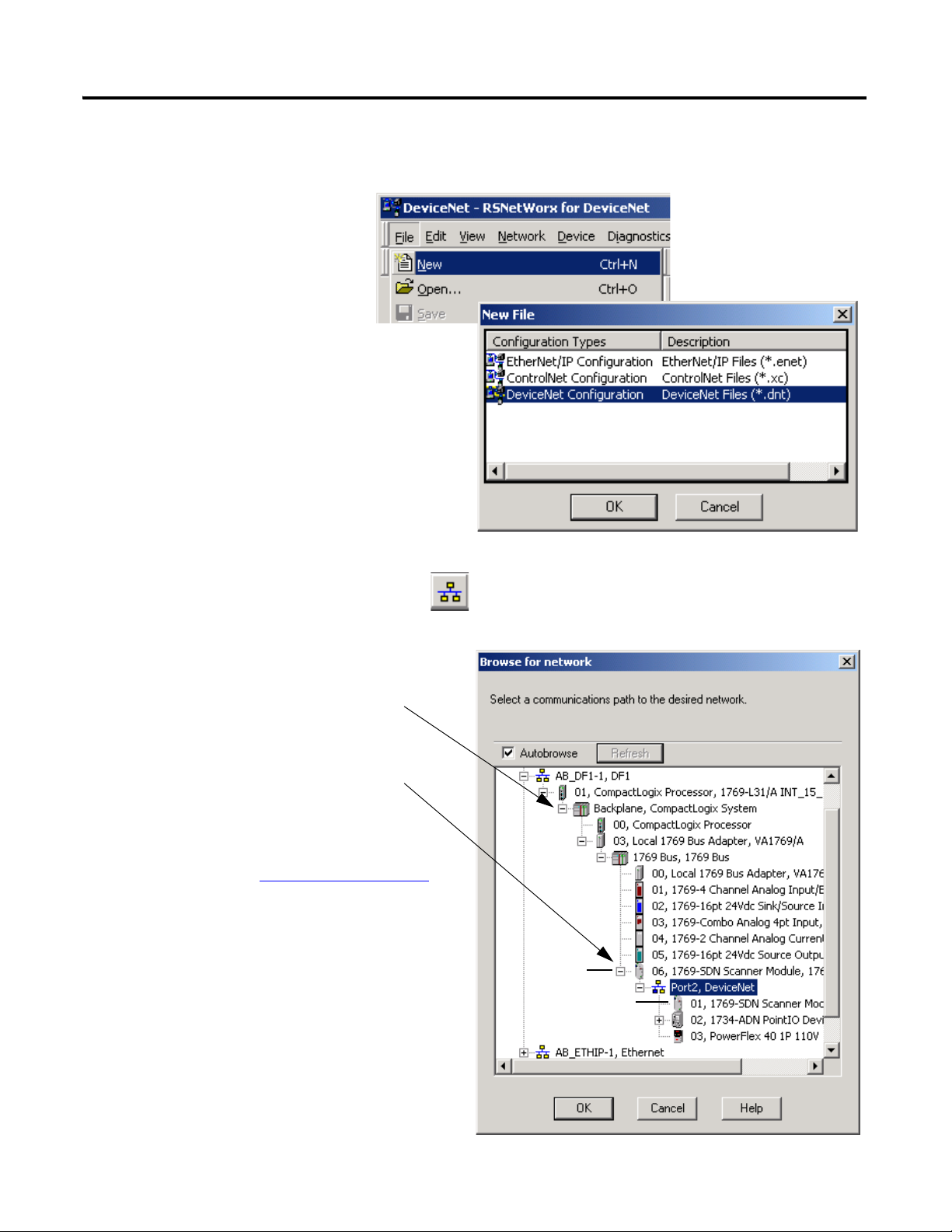
Chapter 9 Configure the DeviceNet Network
1. From the File menu, select
New.
2. Select DeviceNet Configuration and
click OK.
3. Click Who Active to go online.
4. Under AB_DF1-1, expand the
CompactLogix Backplane and the
1769 Bus.
5. Expand the 1769-SDN and the
DeviceNet Port.
6. Record the 1769-SDN module’s slot
number on the Network Worksheet
.
In this example, the 1769-SDN
module is in slot 6 of the 1769 Bus and
is in node 1 on the DeviceNet
network.
7. Select Port2, DeviceNet and click OK.
slot 6
node 1
Create a DeviceNet Configuration File
96 Publication IASIMP-QS001C-EN-P - October 2009
Page 97

8. Click OK.
RSNetWorx software begins browsing the
network.
If your PowerFlex drive does not display, see
Uploading an EDS File From a Drive,
Knowledgebase ID 20539.
TIP
Once all of the devices on your
DeviceNet network appear, you
can click Cancel.
9. Right-click the 1769-SDN module and
choose Properties.
10. Click the Module tab.
11. Click Download.
This clears all configuration from
the 1769-SDN module, synching
the software with the device.
Configure the DeviceNet Network Chapter 9
Publication IASIMP-QS001C-EN-P - October 2009 97
Page 98

Chapter 9 Configure the DeviceNet Network
12. From the Platform pull-down
menu, select CompactLogix.
14. Click OK.
15. Save the file and record the file
name and path on the Network
Worksheet.
This quick start uses the example file
name MainDNet.dnt.
16. Close RSNetWorx for DeviceNet
software.
13. Enter the slot number of the
1769-SDN you recorded on the
Network Worksheet
.
Additional Resources
Resource Description
DeviceNet Modules in Logix5000 Control
Systems, publication DNET-UM004
Uploading an EDS File From a Drive,
Knowledgebase ID 20539,
http://www.rockwellautomation.com/knowled
gebase/
Provides details regarding the installation, configuration, and operation of DeviceNet
modules.
Provides an explanation about uploading EDS files from drives.
98 Publication IASIMP-QS001C-EN-P - October 2009
Page 99

Chapter
10
Create a Project Using RSLogix 5000 Programming
Software
In this chapter you create a project in RSLogix 5000 programming software. In the project
you use ladder logic to create a push button that controls a light on a digital output module.
This project is used in subsequent chapters to test communication with other devices.
Before You Begin
• Configure your network:
– for an EtherNet/IP network, see Chapter 7
– for a ControlNet network, see Chapter 8
– for a DeviceNet network, see Chapter 9
What You Need
• A CompactLogix I/O module with digital outputs, this example uses a 1769-OB16.
• This example includes the following modules as well, but they are not required:
1769-IF4, 1769-IQ16, 1769-IF4XOF2, 1769-OF2.
99Publication IASIMP-QS001C-EN-P - October 2009 99
Page 100

Chapter 10 Create a Project Using RSLogix 5000 Programming Software
Create a Project
Configure the
Controller
Add Local I/O
Modules
Add Ladder Logic to
Test the Local 1769
Compact I/O Modules
Set the
Communication Path
and Download to
the Controller
Add the 1769-SDN
to the Project
page 101
page 103
page 105
page 106
page 109
page 111
Optional
Complete if you have
distributed I/O on the DeviceNet
network.
Follow These Steps
Complete these steps.
100 Publication IASIMP-QS001C-EN-P - October 2009
 Loading...