

Page 1

1768 CompactLogix System
Catalog Numbers
Quick Start
1768-L43 and 1768-L45 CompactLogix Controllers
Page 2
Important User Information
WARNING
IMPORTANT
ATTENTION
SHOCK HAZARD
BURN HAZARD
Solid state equipment has operational characteristics differing from those of electromechanical equipment. Safety Guidelines
for the Application, Installation and Maintenance of Solid State Controls (publication SGI-1.1
Automation sales office or online at http://www.rockwellautomation.com/literature/
between solid state equipment and hard-wired electromechanical devices. Because of this difference, and also because of the
wide variety of uses for solid state equipment, all persons responsible for applying this equipment must satisfy themselves that
each intended application of this equipment is acceptable.
In no event will Rockwell Automation, Inc. be responsible or liable for indirect or consequential damages resulting from the use
or application of this equipment.
The examples and diagrams in this manual are included solely for illustrative purposes. Because of the many variables and
requirements associated with any particular installation, Rockwell Automation, Inc. cannot assume responsibility or liability for
actual use based on the examples and diagrams.
No patent liability is assumed by Rockwell Automation, Inc. with respect to use of information, circuits, equipment, or software
described in this manual.
Reproduction of the contents of this manual, in whole or in part, without written permission of Rockwell Automation, Inc., is
prohibited.
Throughout this manual, when necessary, we use notes to make you aware of safety considerations.
available from your local Rockwell
) describes some important differences
Identifies information about practices or circumstances that can cause an explosion in a hazardous environment,
which may lead to personal injury or death, property damage, or economic loss.
Identifies information that is critical for successful application and understanding of the product.
Identifies information about practices or circumstances that can lead to personal injury or death, property damage,
or economic loss. Attentions help you identify a hazard, avoid a hazard, and recognize the consequence
Labels may be on or inside the equipment, for example, a drive or motor, to alert people that dangerous voltage may
be present.
Labels may be on or inside the equipment, for example, a drive or motor, to alert people that surfaces may reach
dangerous temperatures.
Allen-Bradley, Rockwell Automation, Rockwell Software, Inc., CompactLogix, ControlLogix, FactoryTalk ME, Kinetix, Logix5000, Point I/O, Panelview Plus, PowerFlex, RSLinx, RSLinx Classic, RSLinx Enterprise,
RSLogix, RSLogix 5000, RSLogix 5000 with PhaseManager, RSView Machine Edition, RSView ME, RSView SE, RSView Studio, RSView Enterprise, and TechConnect are trademarks of Rockwell Automation, Inc.
Trademarks not belonging to Rockwell Automation are property of their respective companies.
Page 3
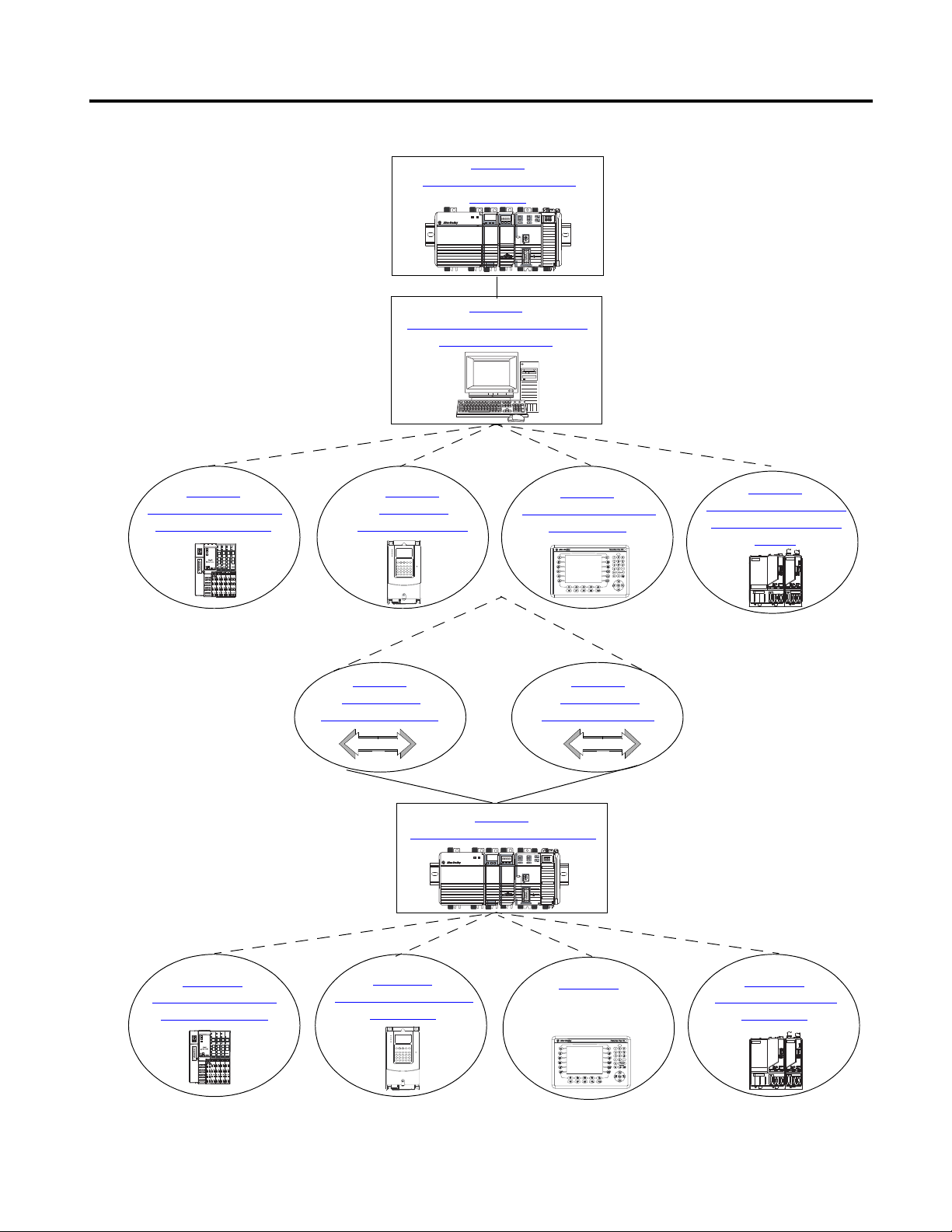
Follow the path that matches your hardware and network configuration.
Chapter 12
Create a PanelView Plus
Application
Chapter
13
Create a Kinetix 6000
Application
Chapter 11
CCreate a PowerFlex 70
Application
Chapter 1
Prepare the CompactLogix
Hardware
Chapter 2
Prepare the Computer and Load
Controller Firmware
Chapter 3
Prepare the Distributed
POINT I/O Hardware
Chapter 6
Prepare the Kinetix 6000
Multi-axis Servo Drive
System
Chapter 5
Prepare the PanelView
Plus Terminal
Chapter 7
Configure the
EtherNet/IP Network
Chapter 8
Configure the
DeviceNet Network
Chapter 9
Create a Project in RSLogix 5000
Chapter 10
Add Distributed Point
I/O Modules to the
Required
Optional
depending on your system
Optional
depending on your network
Required
Optional
depending on your system
Required
Chapter 4
Prepare the
PowerFlex 70 Drive
Where to Start
3Publication IASIMP-QS003B-EN-P - October 2009 3
Page 4
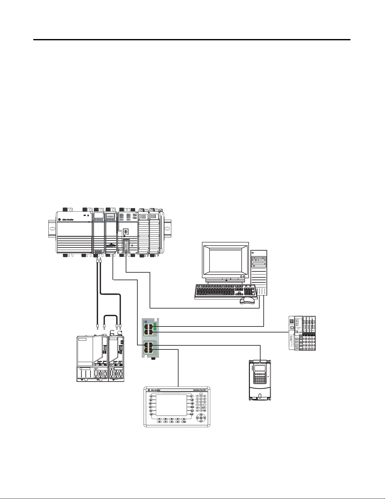
Where to Start
1768-L43 CompactLogix Controller with
1768-ENBT EtherNet/IP and 1768-M04SE SERCOS Modules
Computer with Ethernet Port
Distributed POINT I/O
with 1734-AENT Adapter
PowerFlex 70 Drive with
20-COMM-E Adapter
2711P PanelView Plus Terminal
with Built-in EtherNet/IP Port
Ethernet Switch
1756-CP3
EtherNet/IP
SERCOS
2094 Kinetix 6000
Multi-axis Servo Drive System
Serial
How Hardware Is Connected
This quick start demonstrates CompactLogix L43 and L45 control systems using a single
EtherNet/IP or DeviceNet network for cost-effectiveness and simplified setup. You may
choose to use a multiple network system requiring a combination of EtherNet/IP and
DeviceNet procedures shown in this quick start.
Rockwell Automation also offers many devices other than those in the examples. See your
local Rockwell Automation representative for other device options.
Option 1: 1768-L43 and 1768-L45 Systems with EtherNet/IP Network
4 Publication IASIMP-QS003B-EN-P - October 2009
Page 5
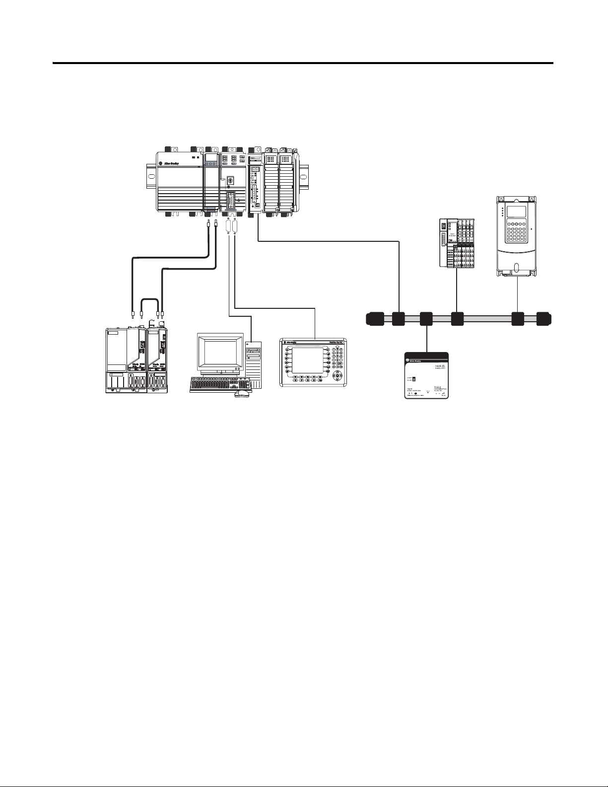
Option 2: 1768-L43 and L45 Systems with DeviceNet Network
1768-L43 CompactLogix Controller with
1768-M04SE SERCOS and 1769-SDN DeviceNet Modules
Distributed POINT I/O
with 1734-ADN Adapter
PowerFlex 70 Drive with
20-COMM-D Adapter
DeviceNet Power Supply
1606-XLDNET8
2711P PanelView Plus Terminal
Computer
Serial
DeviceNet
SERCOS
DeviceNet with KwikLink
flat cable and micro connectors
2094 Kinetix 6000
Multi-axis Servo Drive System
2706-NC13
1756-CP3
Where to Start
Publication IASIMP-QS003B-EN-P - October 2009 5
Page 6
Where to Start
PanelView Plus
AC Line
Filter
Line Interface
Module
PowerFlex 70
Kinetix 6000 Drive Modules
DeviceNet Power Supply
Distributed POINT I/O
Ethernet Switch
1768-L43 CompactLogix System
DeviceNet KwikLink System
E-Stop
Through-the-door
Disconnect
1794-PS3
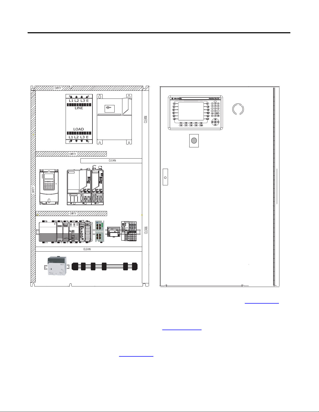
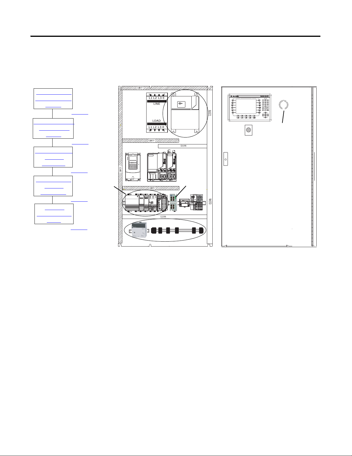
Sample System Panel Layout
The sample panel layout shows the general orientation of 1768-L43 and 1768-L45 system
components for both EtherNet/IP and DeviceNet networks used in this quick start.
For additional panel layout assistance, the Kinetix Accelerator Toolkit CD in Appendix
provides CAD enclosure, component, and wiring diagrams, in DXF format, for most
Rockwell Automation motion components. Refer to the System Design for Control of
Electrical Noise Reference Manual, publication GMC-RM001
For panel layout instructions specific to the Kinetix 6000 drives, refer to the Kinetix 6000
Installation Manual, publication 2094-IN001
B
, for best practice techniques.
.
6 Publication IASIMP-QS003B-EN-P - October 2009
Page 7

Prepare the CompactLogix
Hardware
Table of Contents
Preface
About This Publication . . . . . . . . . . . . . . . . . . . . . . . . . . . . . . . . . . . . . 13
Audience. . . . . . . . . . . . . . . . . . . . . . . . . . . . . . . . . . . . . . . . . . . . . . . . . 14
Required Software . . . . . . . . . . . . . . . . . . . . . . . . . . . . . . . . . . . . . . . . . 14
Parts List: Option 1, 1768-L43 System with EtherNet/IP . . . . . . . . . 15
Parts List: Option 2, 1768-L43 System with DeviceNet . . . . . . . . . . . 17
Conventions . . . . . . . . . . . . . . . . . . . . . . . . . . . . . . . . . . . . . . . . . . . . . . 19
Chapter 1
Introduction . . . . . . . . . . . . . . . . . . . . . . . . . . . . . . . . . . . . . . . . . . . . . . 21
Before You Begin. . . . . . . . . . . . . . . . . . . . . . . . . . . . . . . . . . . . . . . . . . 21
What You Need . . . . . . . . . . . . . . . . . . . . . . . . . . . . . . . . . . . . . . . . . . . 21
Follow These Steps . . . . . . . . . . . . . . . . . . . . . . . . . . . . . . . . . . . . . . . . 22
About the 1768 CompactLogix Controller. . . . . . . . . . . . . . . . . . . . . . 23
Mount and Wire the Line Interface Module. . . . . . . . . . . . . . . . . . . . . 24
Assemble the 1768 CompactLogix System. . . . . . . . . . . . . . . . . . . . . . 25
Make EtherNet/IP Network Connection. . . . . . . . . . . . . . . . . . . . . . . 28
Make DeviceNet Network Connections. . . . . . . . . . . . . . . . . . . . . . . . 29
Wire the 1768-PA3 Power Supply. . . . . . . . . . . . . . . . . . . . . . . . . . . . . 32
Additional Resources . . . . . . . . . . . . . . . . . . . . . . . . . . . . . . . . . . . . . . . 33
Prepare the Computer and Load
Controller Firmware
Prepare the Distributed POINT I/O
Hardware
Chapter 2
Introduction . . . . . . . . . . . . . . . . . . . . . . . . . . . . . . . . . . . . . . . . . . . . . . 35
Before You Begin. . . . . . . . . . . . . . . . . . . . . . . . . . . . . . . . . . . . . . . . . . 35
What You Need . . . . . . . . . . . . . . . . . . . . . . . . . . . . . . . . . . . . . . . . . . . 35
Follow These Steps . . . . . . . . . . . . . . . . . . . . . . . . . . . . . . . . . . . . . . . . 36
Terminology . . . . . . . . . . . . . . . . . . . . . . . . . . . . . . . . . . . . . . . . . . . . . . 37
Make Network Connections for Personal Computer. . . . . . . . . . . . . . 38
Install RSLogix Programming Software . . . . . . . . . . . . . . . . . . . . . . . . 39
Configure a Serial Driver . . . . . . . . . . . . . . . . . . . . . . . . . . . . . . . . . . . . 44
Set the IP Address for the Computer . . . . . . . . . . . . . . . . . . . . . . . . . . 46
Configure the EtherNet/IP Driver in RSLinx Software . . . . . . . . . . . 48
Load the Controller Firmware. . . . . . . . . . . . . . . . . . . . . . . . . . . . . . . . 49
Install Additional Software . . . . . . . . . . . . . . . . . . . . . . . . . . . . . . . . . . 52
Additional Resources . . . . . . . . . . . . . . . . . . . . . . . . . . . . . . . . . . . . . . . 52
Chapter 3
Introduction . . . . . . . . . . . . . . . . . . . . . . . . . . . . . . . . . . . . . . . . . . . . . . 53
Before You Begin. . . . . . . . . . . . . . . . . . . . . . . . . . . . . . . . . . . . . . . . . . 53
What You Need . . . . . . . . . . . . . . . . . . . . . . . . . . . . . . . . . . . . . . . . . . . 53
Follow These Steps . . . . . . . . . . . . . . . . . . . . . . . . . . . . . . . . . . . . . . . . 54
Mount and Connect the Network Adapter. . . . . . . . . . . . . . . . . . . . . . 55
Mount the POINT I/O Modules . . . . . . . . . . . . . . . . . . . . . . . . . . . . . 57
Mount and Wire the POINT I/O Power Supply. . . . . . . . . . . . . . . . . 58
Wire the Adapter and I/O Modules to the Power Supply. . . . . . . . . . 59
Additional Resources . . . . . . . . . . . . . . . . . . . . . . . . . . . . . . . . . . . . . . . 60
7 Publication IASIMP-QS003B-EN-P - October 2009
Page 8

Table of Contents
Prepare the PowerFlex 70 Drive
Prepare the PanelView Plus
Terminal
Chapter 4
Introduction . . . . . . . . . . . . . . . . . . . . . . . . . . . . . . . . . . . . . . . . . . . . . . 61
Before You Begin. . . . . . . . . . . . . . . . . . . . . . . . . . . . . . . . . . . . . . . . . . 61
What You Need . . . . . . . . . . . . . . . . . . . . . . . . . . . . . . . . . . . . . . . . . . . 61
Follow These Steps . . . . . . . . . . . . . . . . . . . . . . . . . . . . . . . . . . . . . . . . 62
Mount and Wire the PowerFlex 70 Drive. . . . . . . . . . . . . . . . . . . . . . . 63
Configure the Communication Adapter . . . . . . . . . . . . . . . . . . . . . . . . 65
Connect Communication Adapter to the PowerFlex 70 Drive . . . . . . 66
Additional Resources . . . . . . . . . . . . . . . . . . . . . . . . . . . . . . . . . . . . . . . 68
Chapter 5
Introduction . . . . . . . . . . . . . . . . . . . . . . . . . . . . . . . . . . . . . . . . . . . . . . 69
Before You Begin. . . . . . . . . . . . . . . . . . . . . . . . . . . . . . . . . . . . . . . . . . 69
What You Need . . . . . . . . . . . . . . . . . . . . . . . . . . . . . . . . . . . . . . . . . . . 69
Follow These Steps . . . . . . . . . . . . . . . . . . . . . . . . . . . . . . . . . . . . . . . . 70
Mount and Wire the PanelView Plus Terminal . . . . . . . . . . . . . . . . . . 71
Make Network Connections for PanelView Plus. . . . . . . . . . . . . . . . . 72
Assign IP Address for PanelView Plus . . . . . . . . . . . . . . . . . . . . . . . . . 73
Upgrade Terminal Firmware . . . . . . . . . . . . . . . . . . . . . . . . . . . . . . . . . 75
Additional Resources . . . . . . . . . . . . . . . . . . . . . . . . . . . . . . . . . . . . . . . 76
Prepare the Kinetix 6000
Multi-axis Servo Drive System
Configure the EtherNet/IP
Network
Chapter 6
Introduction . . . . . . . . . . . . . . . . . . . . . . . . . . . . . . . . . . . . . . . . . . . . . . 77
Before You Begin. . . . . . . . . . . . . . . . . . . . . . . . . . . . . . . . . . . . . . . . . . 77
What You Need . . . . . . . . . . . . . . . . . . . . . . . . . . . . . . . . . . . . . . . . . . . 77
Follow These Steps . . . . . . . . . . . . . . . . . . . . . . . . . . . . . . . . . . . . . . . . 78
Mount and Bond the Power Rail. . . . . . . . . . . . . . . . . . . . . . . . . . . . . . 79
Mount the Integrated Axis and Axis Module . . . . . . . . . . . . . . . . . . . . 80
Wire Power to the Integrated Axis Module . . . . . . . . . . . . . . . . . . . . . 82
Wire Servo Motors to Integrated Axis and Axis Modules . . . . . . . . . . 83
Connect the SERCOS Fiber Optic Cables . . . . . . . . . . . . . . . . . . . . . . 84
Set the SERCOS Node Address . . . . . . . . . . . . . . . . . . . . . . . . . . . . . . 85
Additional Resources . . . . . . . . . . . . . . . . . . . . . . . . . . . . . . . . . . . . . . . 86
Chapter 7
Introduction . . . . . . . . . . . . . . . . . . . . . . . . . . . . . . . . . . . . . . . . . . . . . . 87
Before You Begin. . . . . . . . . . . . . . . . . . . . . . . . . . . . . . . . . . . . . . . . . . 87
What You Need . . . . . . . . . . . . . . . . . . . . . . . . . . . . . . . . . . . . . . . . . . . 87
Follow These Steps . . . . . . . . . . . . . . . . . . . . . . . . . . . . . . . . . . . . . . . . 88
Terminology . . . . . . . . . . . . . . . . . . . . . . . . . . . . . . . . . . . . . . . . . . . . . . 88
Assign IP Addresses. . . . . . . . . . . . . . . . . . . . . . . . . . . . . . . . . . . . . . . . 89
Browse the EtherNet/IP Network in RSLinx Classic Software . . . . . 91
Additional Resources . . . . . . . . . . . . . . . . . . . . . . . . . . . . . . . . . . . . . . . 92
8 Publication IASIMP-QS003B-EN-P - October 2009
Page 9

Configure the DeviceNet Network
Create a Project in RSLogix 5000
Programming Software
Table of Contents
Chapter 8
Introduction . . . . . . . . . . . . . . . . . . . . . . . . . . . . . . . . . . . . . . . . . . . . . . 93
Before You Begin. . . . . . . . . . . . . . . . . . . . . . . . . . . . . . . . . . . . . . . . . . 93
What You Need . . . . . . . . . . . . . . . . . . . . . . . . . . . . . . . . . . . . . . . . . . . 93
Follow These Steps . . . . . . . . . . . . . . . . . . . . . . . . . . . . . . . . . . . . . . . . 94
Apply Power to the DeviceNet Network . . . . . . . . . . . . . . . . . . . . . . . 94
Set the Node Address of the DeviceNet Scanner . . . . . . . . . . . . . . . . 95
Create a DeviceNet Configuration File. . . . . . . . . . . . . . . . . . . . . . . . . 97
Additional Resources . . . . . . . . . . . . . . . . . . . . . . . . . . . . . . . . . . . . . . 100
Chapter 9
Introduction . . . . . . . . . . . . . . . . . . . . . . . . . . . . . . . . . . . . . . . . . . . . . 101
Before You Begin. . . . . . . . . . . . . . . . . . . . . . . . . . . . . . . . . . . . . . . . . 101
What You Need . . . . . . . . . . . . . . . . . . . . . . . . . . . . . . . . . . . . . . . . . . 101
Follow These Steps . . . . . . . . . . . . . . . . . . . . . . . . . . . . . . . . . . . . . . . 102
Create a Project . . . . . . . . . . . . . . . . . . . . . . . . . . . . . . . . . . . . . . . . . . 103
Configure 1768-ENBT Ethernet Module. . . . . . . . . . . . . . . . . . . . . . 104
Configure 1769-SDN DeviceNet Module . . . . . . . . . . . . . . . . . . . . . 105
Configure 1769 Local I/O Modules . . . . . . . . . . . . . . . . . . . . . . . . . . 107
Verify I/O Configuration . . . . . . . . . . . . . . . . . . . . . . . . . . . . . . . . . . 108
Add Ladder Logic to Test Local 1769 Compact I/O Modules. . . . . 109
Set the Project Path and Download to the Controller . . . . . . . . . . . . 112
Additional Resources . . . . . . . . . . . . . . . . . . . . . . . . . . . . . . . . . . . . . . 114
Add Distributed Point I/O Modules
to the Project
Chapter 10
Introduction . . . . . . . . . . . . . . . . . . . . . . . . . . . . . . . . . . . . . . . . . . . . . 115
Before You Begin. . . . . . . . . . . . . . . . . . . . . . . . . . . . . . . . . . . . . . . . . 115
What You Need . . . . . . . . . . . . . . . . . . . . . . . . . . . . . . . . . . . . . . . . . . 115
Follow These Steps . . . . . . . . . . . . . . . . . . . . . . . . . . . . . . . . . . . . . . . 116
Add Distributed I/O Modules . . . . . . . . . . . . . . . . . . . . . . . . . . . . . . 117
Configure the DeviceNet Subnet . . . . . . . . . . . . . . . . . . . . . . . . . . . . 120
Configure the 1734-ADN Properties . . . . . . . . . . . . . . . . . . . . . . . . . 123
Create a DeviceNet Scanlist. . . . . . . . . . . . . . . . . . . . . . . . . . . . . . . . . 126
Add Ladder Logic . . . . . . . . . . . . . . . . . . . . . . . . . . . . . . . . . . . . . . . . 128
Create DeviceNet Tags and Add Ladder Logic . . . . . . . . . . . . . . . . . 130
Download the Project . . . . . . . . . . . . . . . . . . . . . . . . . . . . . . . . . . . . . 135
Test the Distributed I/O Light . . . . . . . . . . . . . . . . . . . . . . . . . . . . . . 136
Additional Resources . . . . . . . . . . . . . . . . . . . . . . . . . . . . . . . . . . . . . . 136
Publication IASIMP-QS003B-EN-P - October 2009 9
Page 10

Table of Contents
Create a PowerFlex 70 Application
Create a PanelView Plus
Application
Chapter 11
Introduction . . . . . . . . . . . . . . . . . . . . . . . . . . . . . . . . . . . . . . . . . . . . . 137
Before You Begin. . . . . . . . . . . . . . . . . . . . . . . . . . . . . . . . . . . . . . . . . 137
What You Need . . . . . . . . . . . . . . . . . . . . . . . . . . . . . . . . . . . . . . . . . . 137
Follow These Steps . . . . . . . . . . . . . . . . . . . . . . . . . . . . . . . . . . . . . . . 138
Add the Drive to Your RSLogix 5000 Project . . . . . . . . . . . . . . . . . . 139
Edit the Drive Parameters . . . . . . . . . . . . . . . . . . . . . . . . . . . . . . . . . . 143
Create a DeviceNet Scanlist. . . . . . . . . . . . . . . . . . . . . . . . . . . . . . . . . 145
Create DeviceNet Tags . . . . . . . . . . . . . . . . . . . . . . . . . . . . . . . . . . . . 149
Download the Project . . . . . . . . . . . . . . . . . . . . . . . . . . . . . . . . . . . . . 152
Test the PowerFlex 70 Tags . . . . . . . . . . . . . . . . . . . . . . . . . . . . . . . . 153
Additional Resources . . . . . . . . . . . . . . . . . . . . . . . . . . . . . . . . . . . . . . 159
Chapter 12
Introduction . . . . . . . . . . . . . . . . . . . . . . . . . . . . . . . . . . . . . . . . . . . . . 161
Before You Begin. . . . . . . . . . . . . . . . . . . . . . . . . . . . . . . . . . . . . . . . . 161
What You Need . . . . . . . . . . . . . . . . . . . . . . . . . . . . . . . . . . . . . . . . . . 161
Follow These Steps . . . . . . . . . . . . . . . . . . . . . . . . . . . . . . . . . . . . . . . 162
Create a New Application . . . . . . . . . . . . . . . . . . . . . . . . . . . . . . . . . . 163
Create an RSLinx Enterprise Configuration in
FactoryTalkView ME . . . . . . . . . . . . . . . . . . . . . . . . . . . . . . . . . . . 164
Create Device Shortcuts to the Controller . . . . . . . . . . . . . . . . . . . . . 166
Create the OB16_Light Indicator . . . . . . . . . . . . . . . . . . . . . . . . . . . . 170
Create a Push Button . . . . . . . . . . . . . . . . . . . . . . . . . . . . . . . . . . . . . . 173
Test the Indicator and Push Button . . . . . . . . . . . . . . . . . . . . . . . . . . 175
Add a Goto Configuration Mode Button . . . . . . . . . . . . . . . . . . . . . . 176
Assign Keys . . . . . . . . . . . . . . . . . . . . . . . . . . . . . . . . . . . . . . . . . . . . . 177
Assign an Initial Screen . . . . . . . . . . . . . . . . . . . . . . . . . . . . . . . . . . . . 178
Transfer the Application to the PanelView Plus Terminal. . . . . . . . . 179
Test the Application on the PanelView Plus Terminal . . . . . . . . . . . 181
Additional Resources . . . . . . . . . . . . . . . . . . . . . . . . . . . . . . . . . . . . . . 182
Chapter 13
Create a Kinetix 6000 Application
10 Publication IASIMP-QS003B-EN-P - October 2009
Introduction . . . . . . . . . . . . . . . . . . . . . . . . . . . . . . . . . . . . . . . . . . . . . 183
Before You Begin. . . . . . . . . . . . . . . . . . . . . . . . . . . . . . . . . . . . . . . . . 183
What You Need . . . . . . . . . . . . . . . . . . . . . . . . . . . . . . . . . . . . . . . . . . 183
Follow These Steps . . . . . . . . . . . . . . . . . . . . . . . . . . . . . . . . . . . . . . . 184
Enable Coordinated System Time Master . . . . . . . . . . . . . . . . . . . . . 185
Create the Motion Group . . . . . . . . . . . . . . . . . . . . . . . . . . . . . . . . . . 186
Configure Your Logix SERCOS Module . . . . . . . . . . . . . . . . . . . . . . 187
Configure Your Kinetix IAM and AM Modules . . . . . . . . . . . . . . . . 189
Configure Axis Properties . . . . . . . . . . . . . . . . . . . . . . . . . . . . . . . . . . 192
Save and Download Your Program. . . . . . . . . . . . . . . . . . . . . . . . . . . 193
Test the Kinetix Application File . . . . . . . . . . . . . . . . . . . . . . . . . . . . 195
Additional Resources . . . . . . . . . . . . . . . . . . . . . . . . . . . . . . . . . . . . . . 196
Page 11

Network Information
Kinetix Accelerator Toolkit
Motion Anaylzer
Table of Contents
Appendix A
Network Information. . . . . . . . . . . . . . . . . . . . . . . . . . . . . . . . . . . . . . 197
Appendix B
Sample Panel Layout . . . . . . . . . . . . . . . . . . . . . . . . . . . . . . . . . . . 199
Simplified Wiring . . . . . . . . . . . . . . . . . . . . . . . . . . . . . . . . . . . . . . 199
Preconfigured HMI . . . . . . . . . . . . . . . . . . . . . . . . . . . . . . . . . . . . 199
Preconfigured Logic. . . . . . . . . . . . . . . . . . . . . . . . . . . . . . . . . . . . 199
Diagnostic Tools . . . . . . . . . . . . . . . . . . . . . . . . . . . . . . . . . . . . . . 200
Kinetix Accelerator Toolkit CD . . . . . . . . . . . . . . . . . . . . . . . . . . 200
Appendix C
Motion Analyzer. . . . . . . . . . . . . . . . . . . . . . . . . . . . . . . . . . . . . . . . . . 201
Publication IASIMP-QS003B-EN-P - October 2009 11
Page 12

Table of Contents
12 Publication IASIMP-QS003B-EN-P - October 2009
Page 13

Preface
About This Publication
This quick start provides examples and procedures for 1768-L43 and 1768-L45
CompactLogix systems. It includes version 18 release updates for RSLogix 5000
programming software. These procedures cover many common user tasks, such as:
• connecting the controller to multiple devices including local and distributed I/O, drives,
Kinetix 6000 servo drives, and a PanelView Plus terminal.
• connecting and configuring EtherNet/IP, DeviceNet, and serial networks using
CompactLogix systems.
• creating and monitoring controller programs.
The examples are designed to get devices installed and communicating with each other in the
simplest way possible. The programming examples are not complex, and offer easy solutions
to verify that devices are communicating properly.
The beginning of each chapter contains the following information. Read these sections
carefully before beginning work in each chapter.
• Before You Begin - This section lists the steps that must be completed and decisions
that must be made before starting that chapter. Because the chapters in this quick start
do not have to be completed in the order in which they appear, this section defines the
minimum amount of preparation required before completing the current chapter.
• What You Need - This section lists the tools that are required to complete the steps in
the current chapter. This includes, but is not limited to, hardware and software.
• Follow These Steps - This section illustrates the steps in the current chapter and
identifies which steps are required to complete the examples using specific networks.
Also note that the electronic version of this publication contains links to pages within
publications for easier navigation. Click on any chapter title, chapter number, topic title, or
page number to follow a link to the item.
13Publication IASIMP-QS003B-EN-P - October 2009 13
Page 14

Audience
This quick start was created to assist experienced or new industrial control users not familiar
with the CompactLogix controllers or Integrated Architecture products of Rockwell
Automation.
Required Software
The table lists software required to complete the examples in this quick start. Some software
is required regardless of the 1768 CompactLogix system you use and other software is
dependent on the network and devices in the system.
Rockwell Automation Version Required for
RSLogix 5000 programming software 18
RSNetWorx for DeviceNet software 7.0 DeviceNet network
FactoryTalkView Machine Edition software
Includes:
• Factory Talk Services
• RSLinx Enterprise
• RSLinx Lite (Classic)
All 1768-L43 and 1768-L45
systems
PanelView Plus terminals
14 Publication IASIMP-QS003B-EN-P - October 2009
Page 15

Parts List: Option 1, 1768-L43 and 1768-L45 Systems with EtherNet/IP
The table lists the parts for the 1768-L43 and 1768-L45 systems with an EtherNet/IP
network and a 200/230V Kinetix 6000 Multi-axis Servo Drive System.
Parts List: Option 1, 1768-L43 and 1768-L45 Systems with EtherNet/IP Network
General Configuration
Quantity Catalog Number Description
1 1768-L43 and 1768-L45 CompactLogix Controller
1 1768-PA3 CompactLogix Power Supply
1 1769-ECR Compact I/O Right End Cap/Terminator
1 1769-IF4 Compact 4 Channel Analog Current/Voltage Input Module
1 1769-IQ16 Compact 16 Point 24V dc Sinking/Sourcing Input Module
1 1769-IF4XOF2 Compact 8 Bit Resolution, High Speed 4 In/2 Out Analog Combination Module
1 1769-OF2 Compact 2 Channel Analog Current/Voltage Output Module
1
1
1
1
1 1734-TB Wiring Base w/ Removable IEC Screw Terminals (Quantity of 10)
1 1794-PS13 FLEX I/O 85-264V ac to 24V dc 1.3A Power Supply
1 20AB4P2A3AYNNNNN PowerFlex 70 Drive.
1 2711P-B10C4D1 PanelView Plus 10 inch color keypad/touch terminal with EtherNet/IP and RS-232
1 1747-CP3 or 1756-CP3 RS-232 cable for connection between the 1768-L43 controller and personal computer
1 64-134 DIN rail (steel not aluminum), 1 m
EtherNet/IP Configuration
1 1768-ENBT CompactLogix EtherNet/IP Communication Module
1 1734-AENT POINT I/O Ethernet Adapter
1 20-COMM-E PowerFlex 70 EtherNet/IP Adapter
1 Ethernet Switch
6 Non Rockwell Automation Ethernet CAT5 Straight-through cables
1769-OB16
1734-IB4
1734-OB4E
1734-OE2C
(2)
(1)
(2) (3)
(2)
Compact 16 Point 24V dc Sourcing Output Module
POINT I/O 4 Sink Input Module
POINT I/O 4 Protected Output Module
POINT I/O 2 Current Output Analog Module
Publication IASIMP-QS003B-EN-P - October 2009 15
Page 16

Parts List: Option 1, 1768-L43 and 1768-L45 Systems with EtherNet/IP Network
Quantity Catalog Number Description
Kinetix 6000 Servo Drive System - 200/230V (The quantity, size, and cat. nos. for the Kinetix equipment will vary by application motion requirements.)
1
1
1768-M04SE
2094-AL75S
(4)
SERCOS interface module installs in 1768 CompactLogix controller and connects to
Integrated Axis modules or Axis modules.
Line Interface Module (LIM), 230V, 75 A
1 140U-H-RVM12R Through-the-door Disconnect for LIM
1 2090-XXLF-X330B Line Filter, 3-phase, 30 A ac
1 2094-PRS2 Power Rail, 2-slot, Slim
1 2094-AC09-M02 Integrated Axis Module (IAM), 6 kW Converter and 19 A Inverter Output
1 2094-AM01 Axis Module (AM), 9 A Inverter Output
1 MPL-A310P-MK22AA MP-Series Low Inertia Motor, 0.73 kW Output with Absolute, Multi-turn Feedback
2 2090-XXNPMP-16S03 Motor Power Cable: 3 m (9.8 ft)
2 2090-UXNFBMP-S03 Motor Feedback Cable, 3 m (9.8 ft)
2 2090-SCEP0-9 SERCOS Fiber Optic Cable, 0.9 m (2.9 ft)
1 2090-SCEP0-1 SERCOS Fiber Optic Cable, 0.1 m (5.1 in.)
(1)
The 1769-OB16 is the only Compact I/O module used in this quick start. The other modules are added as examples only and are not required.
(2)
Use POINT I/O modules at series C or later to complete examples in this quick start.
(3)
The 1734-OB4E module is the only POINT I/O module used in this quick start. The other modules are added as examples only and are not required.
(4)
The 2094-AL75S line interface module (LIM) is optional. Individual components can be purchased separately instead of the LIM.
16 Publication IASIMP-QS003B-EN-P - October 2009
Page 17

Parts List: Option 2, 1768-L43 and 1768-L45 Systems with DeviceNet
The table lists the parts for a 1768-L43 and 1768-L45 Systems with DeviceNet I/O, serial
connections, and a 200/230V Kinetix 6000 Multi-axis Servo Drive System.
Parts List: Option 2, 1768-L43 and 1768-L45 Systems with DeviceNet Network
General Configuration
Quantity Catalog Number Description
1 1768-L43 and 1768-L45 CompactLogix Controller
1 1768-PA3 CompactLogix Power Supply
1 1769-ECR Compact I/O Right End Cap/Terminator
1 1769-IF4 Compact 4 Channel Analog Current/Voltage Input Module
1 1769-IQ16 Compact 16 Point 24V dc Sinking/Sourcing Input Module
1 1769-IF4XOF2 Compact 8 Bit Resolution, High Speed 4 In/2 Out Analog Combination Module
1 1769-OF2 Compact 2 Channel Analog Current/Voltage Output Module
1
1
1
1
1 1734-TB Wiring Base w/ Removable IEC Screw Terminals (Quantity of 10)
1 1794-PS13 FLEX I/O 85-264V ac to 24V dc 1.3A Power Supply
1 20AB4P2A3AYNNNNN PowerFlex 70 Drive
1 2711P-B10C4D1 PanelView Plus 10 inch color keypad/touch terminal with EtherNet/IP and RS-232
1 1747-CP3 or 1756-CP3 RS-232 cable for connection between the 1768-L43 controller and personal computer
1 2711-NC13 RS-232 cable for connection between the PanelView Plus terminal and the 1768-L43
1 64-134 DIN rail (steel not aluminum), 1 m
DeviceNet Configuration
1 1769-SDN Compact DeviceNet Scanner
1 1734-ADN POINT I/O DeviceNet Adapter
1 20-COMM-D PowerFlex 70 DeviceNet Adapter
1 1606-XLDNET8 DeviceNet Power Supply
1 1485C-P1E75 KwikLink Flat Cable, 75 m
2 1485A-T1E4 KwikLink Terminator/Resistor
3 1485P-P1E4-R5 KwikLink Sealed Micro Connector
3 1485K-P1F5-C KwikLink QD Cordset Micro Right-Angle Male
1 1485T-P1E4-B1 KwikLink Power Tap Module
1769-OB16
1734-IB4
1734-OB4E
1734-OE2C
(2)
(1)
(2) (3)
(2)
Compact 16 Point 24V dc Sourcing Output Module
POINT I/O 4 Sink Input Module
POINT I/O 4 Protected Output Module
POINT I/O 2 Current Output Analog Module
controller or personal computer
Publication IASIMP-QS003B-EN-P - October 2009 17
Page 18

Parts List: Option 2, 1768-L43 and 1768-L45 Systems with DeviceNet Network
Quantity Catalog Number Description
Kinetix 6000 Servo Drive System - 200/230V (The quantity, size, and cat. nos. for the Kinetix equipment will vary by application motion requirements.)
1
1
1768-M04SE
2094-AL75S
(4)
SERCOS interface module installs in 1768 CompactLogix controller and connects to
Integrated Axis modules or Axis modules.
Line Interface Module (LIM), 230V, 75 A
1 140U-H-RVM12R Through-the-door Disconnect for LIM
1 2090-XXLF-X330B Line Filter, 3-phase, 30 A ac
1 2094-PRS2 Power Rail, 2-slot, Slim
1 2094-AC09-M02 Integrated Axis Module (IAM), 6 kW Converter and 19 A Inverter Output
1 2094-AM01 Axis Module (AM), 9 A Inverter Output
1 MPL-A310P-MK22AA MP-Series Low Inertia Motor, 0.73 kW Output with Absolute, Multi-turn Feedback
2 2090-XXNPMP-16S03 Motor Power Cable: 3 m (9.8 ft)
2 2090-UXNFBMP-S03 Motor Feedback Cable, 3 m (9.8 ft)
2 2090-SCEP0-9 SERCOS Fiber Optic Cable, 0.9 m (2.9 ft)
1 2090-SCEP0-1 SERCOS Fiber Optic Cable, 0.1 m (5.1 in.)
(1)
The 1769-OB16 module is the only Compact I/O module used in this quick start. The other modules are added as examples only and are not required.
(2)
Use POINT I/O modules at series C or later to complete examples in this quick start.
(3)
The 1734-OB4E module is the only POINT I/O module used in this quick start. The other modules are added as examples only and are not required.
(4)
The 2094-AL75S line interface module (LIM) is optional. Individual components can be purchased separately instead of the LIM.
18 Publication IASIMP-QS003B-EN-P - October 2009
Page 19

Conventions
This manual uses the following conventions.
Convention Meaning Example
Courier
font
Check or uncheck Click to activate or deactivate a checkbox. Check the Disable Keying checkbox.
Click
Double-click
Type or enter text exactly as shown. Type cmd.
Click the left mouse button once while the cursor is positioned
on object or selection.
Click the left mouse button twice in quick succession while the
cursor is positioned on object or selection.
Click Browse.
Double-click the application icon.
Expand
Right-click
Select Click to highlight a menu item or list choice. Select New Module from the pull-down list.
> Shows nested menu selections as menu name followed by menu
Click the + to the left of a given item /folder to show its
contents.
Click the right mouse button once while the cursor is positioned
on object or selection.
selection.
Expand 1768 Bus under I/O Configuration.
Right-click the 1768 Bus icon.
Select File
>Menu.
Publication IASIMP-QS003B-EN-P - October 2009 19
Page 20

Notes:
20 Publication IASIMP-QS003B-EN-P - October 2009
Page 21

Chapter
1
Prepare the CompactLogix Hardware
Introduction
In this chapter, you install your CompactLogix hardware including the controller, power
supply, 1768 SERCOS module, and the 2094 line interface module. The line interface module
will power the 1768 CompactLogix and Kinetix 6000 system components. Depending on
your configuration, you also install the 1768 EtherNet/IP module, 1769 DeviceNet module,
and local 1769 I/O modules.
Before You Begin
Determine which network and appropriate hardware to use.
• For an EtherNet/IP network (option 1), use the 1768-ENBT module with the
controller.
• For a DeviceNet (option 2), use the 1769-SDN module with the controller.
• For a motion application (option 1 or 2), use a 1768-M04SE SERCOS module with the
controller.
What You Need
• 2094-AL75S line interface module (optional)
• 1768-L43 or 1768-L45 CompactLogix controller
• 1768-PA3 CompactLogix power supply
• 1769-ECR end cap
• 1768-ENBT EtherNet/IP module for an EtherNet/IP network (option 1)
– Ethernet switch and standard CAT5 Ethernet cable for EtherNet/IP network
• 1768-M04SE SERCOS module for motion on either network (option 1 or 2)
• 1769-SDN DeviceNet module for a DeviceNet network (option 2)
– 1606-XLDNET8 power supply and KwikLink Power Tap module for DeviceNet
network
– KwikLink right-angle male cables with sealed microconnectors, connected to a flat
cable with terminator/resistor on each end for a DeviceNet network
• 1769 Compact I/O modules
• Serial 1756-CP3 cable for EtherNet/IP and DeviceNet networks
21Publication IASIMP-QS003B-EN-P - October 2009 21
Page 22
Chapter 1 Prepare the CompactLogix Hardware
page 25
Assemble the 1768
CompactLogix
System
Make EtherNet/IP
Network
Connection
Wire the
1768-PA3 Power
Supply
page 28
page 32
page 24
Mount and Wire
the Line Interface
Module
Make DeviceNet
Network
Connections
page 29
1768
CompactLogix
System
Line Interface
Module
Ethernet
Switch
DeviceNet Network
Through-the-door
Disconnect for
LIM Module
Follow These Steps
Complete the appropriate steps to assemble your 1768-L43/L45 CompactLogix hardware.
22 Publication IASIMP-QS003B-EN-P - October 2009
Page 23
Prepare the CompactLogix Hardware Chapter 1
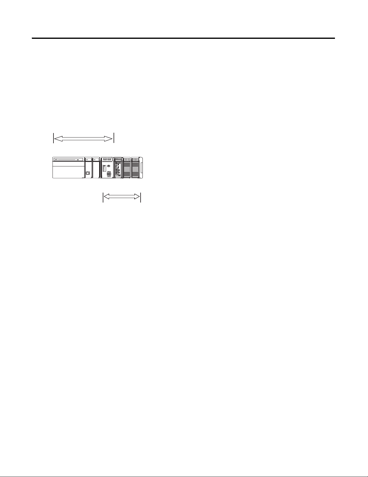
Slot 0
Slot 1
Slot 2
Slot 2
Slot 1
Slot 0
Slot 3
1768
1769
About the 1768 CompactLogix Controller
The 1768-L43 and 1768-L45 CompactLogix controllers combine a 1768 backplane and a
1769 backplane. The 1768 backplane supports the 1768 controller, the 1768 power supply,
and a maximum of two 1768 modules, such as the EtherNet/IP module and the SERCOS
interface module. The 1769 backplane supports 1769 modules, such as the 1769 DeviceNet
module and 1769 I/O modules.
Publication IASIMP-QS003B-EN-P - October 2009 23
Page 24
Chapter 1 Prepare the CompactLogix Hardware
WARNING
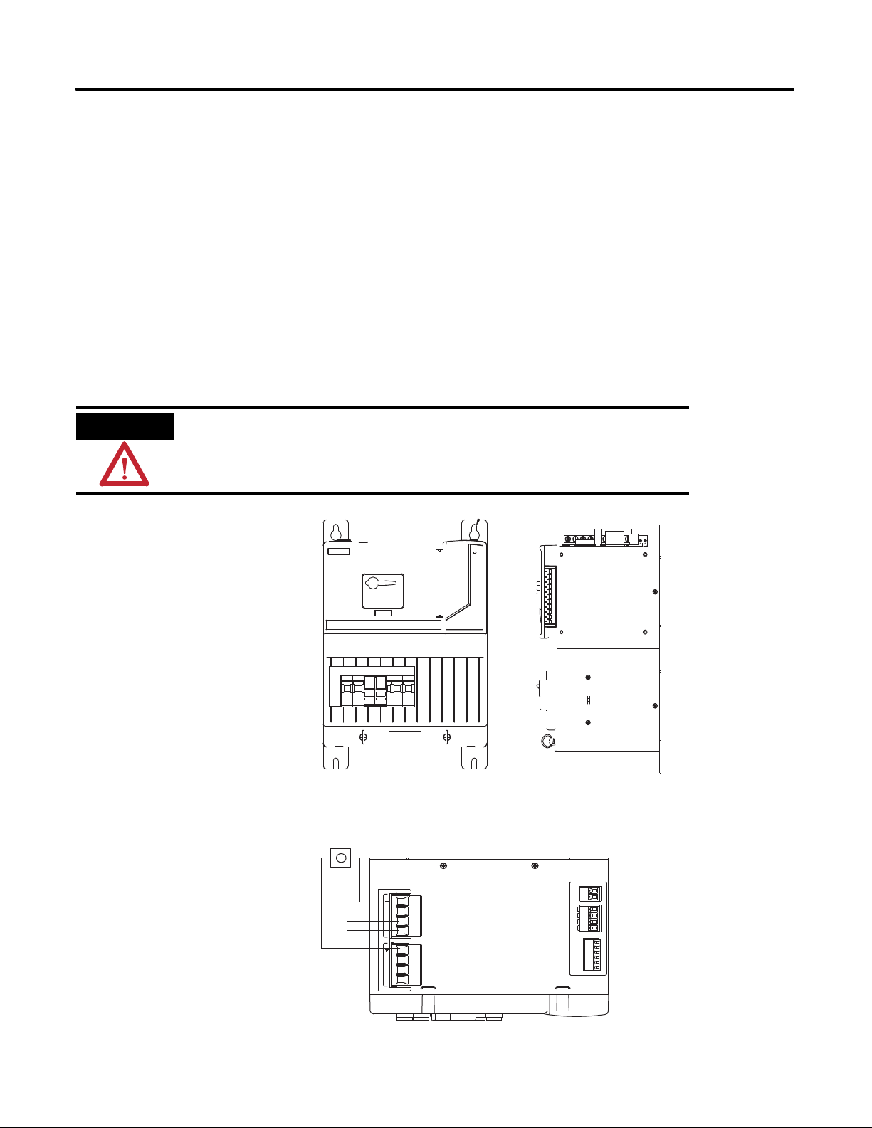
Mount and Wire the Line Interface Module
2094-AL75S or Equivalent Hardware, Required for EtherNet/IP and DeviceNet Systems
The line interface module (LIM) serves as the power connection and the generation point for
the complete power needs of most control panels. The LIM module provides the control of
three-phase power and the drive logic power, and also serves as the source and circuit
protection of power for the controller, I/O, and other panel devices. A single LIM module
can replace nine individual components, eliminating up to 100 interconnecting wire
terminations. The 2094-AL75S line interface module (LIM) is optional. Individual
components can be purchased separately instead of purchasing the LIM.
Verify that all incoming power is turned off before wiring power to the LIM
module or any other devices in this chapter.
1. Lay out the position of
the LIM module in the
enclosure.
2. Attach the LIM module
to the cabinet by using
M6 (1/4 in.) bolts.
3. Tighten all mounting
fasteners.
4. Mount the
through-the-door
disconnect switch for the
LIM module.
5. Wire 230V 3-phase
incoming power to the
LIM module and
6. Bond the ground
terminal to the panel.
L3
L2
L1
MAIN VAC
L3
L2
L1
195-265 VAC LINE, 50/60 Hz
L3'
L2'
L1'
195-265 VAC LOAD, 50/60 Hz
1 2 3 4
1 2 3 4
CONTROL VAC
CTRL2
1 2
CTRL1
230 VAC SUPPLY
AUX2
AUX2
AUX1
AUX1
1 2 3 4
I/O_COM
24 VDC SUPPLY
I/O_PWR
I/O_COM
I/O_PWR
I/O_COM
I/O_PWR
1 2 3 4 5 6
24 Publication IASIMP-QS003B-EN-P - October 2009
Page 25
Prepare the CompactLogix Hardware Chapter 1
a
b
2
b
c
d
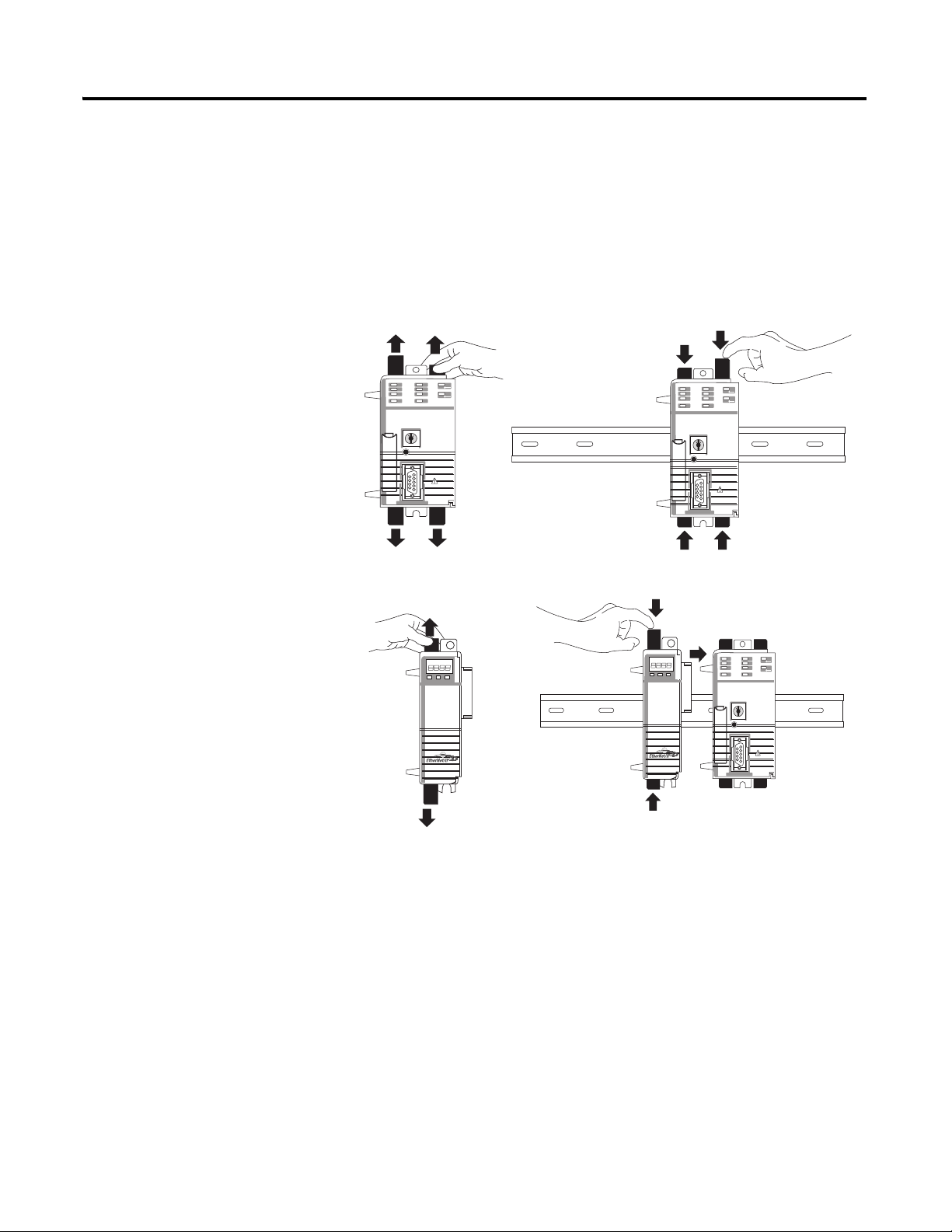
Assemble the 1768 CompactLogix System
1768-L43 Controller, 1768-L45 Controller, 1768-PA3 Power Supply, 1768-ENBT,
1768-M04SE, 1769-SDN, 1769 Local I/O Modules, 1769-ECR End Cap Terminator
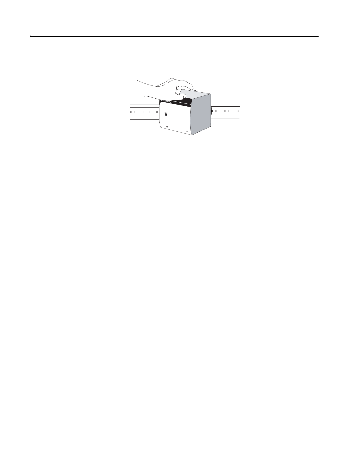
1. Mount the 1768-L43 or
1768-L45 controller on
the DIN rail.
a. Pull locking tabs out.
b. Slide controller into
position and push
locking tabs in.
2. If you have an
EtherNet/IP module:
a. locate the Ethernet
(MAC) address on the
side of module and
record address in
Appendix A.
b. pull locking tabs out.
c. align module to the left
of controller on DIN
rail and slide the mating
connector into the
1768-L43 or 1768-L45
controller.
d. push locking tabs in.
Publication IASIMP-QS003B-EN-P - October 2009 25
Page 26
Chapter 1 Prepare the CompactLogix Hardware
b
a
c
a
b
c
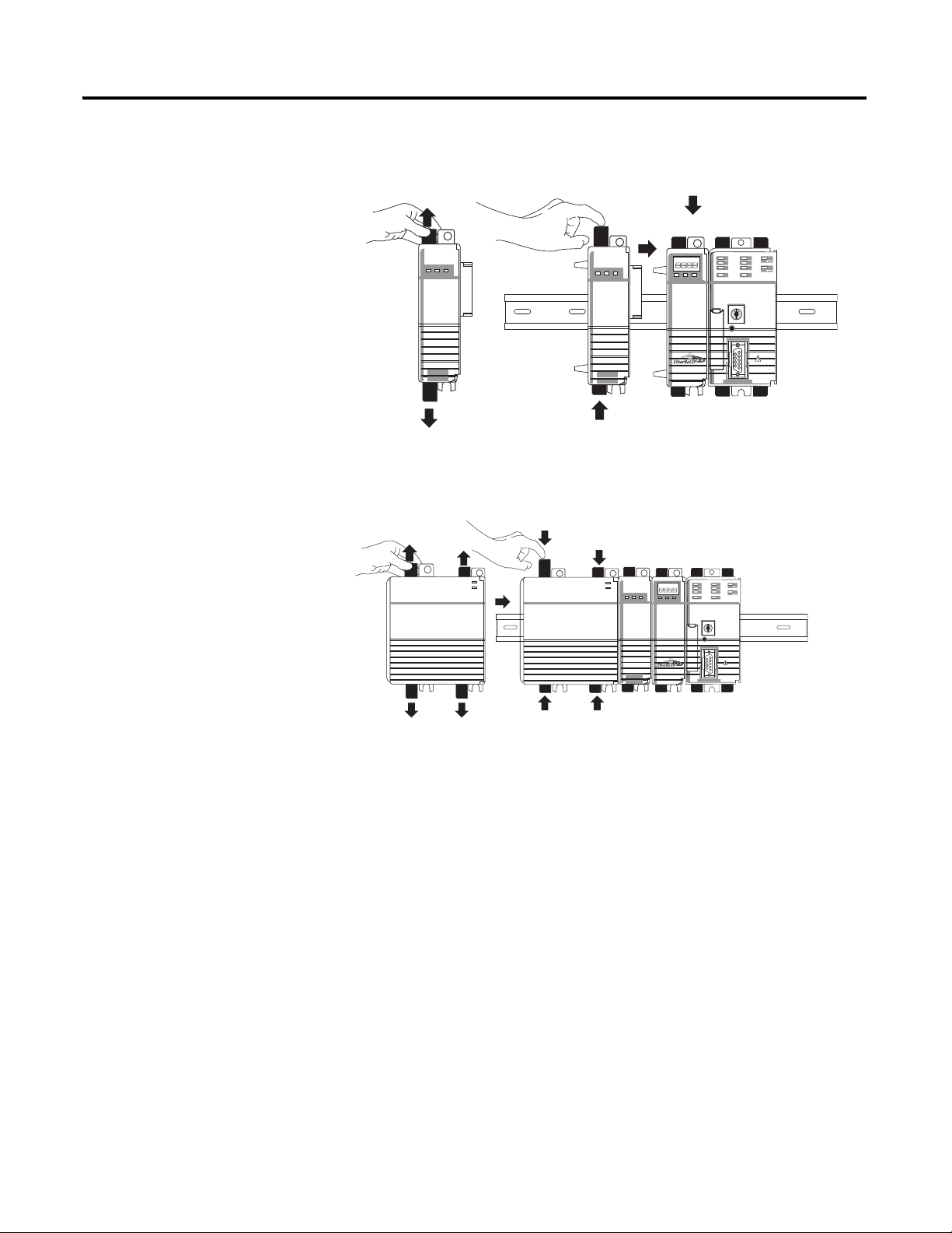
3. Mount the SERCOS
1768-M04SE module.
a. Pull locking tabs out.
b. Align SERCOS module
to the left of
EtherNet/IP module
or controller and slide
into place.
c. Push locking tabs in.
4. Mount the power supply
on the DIN rail.
a. Pull locking tabs out.
b. Align supply to the left
of the SERCOS
module and slide into
place.
c. Push locking tabs in.
5. If you have a 1769-SDN
DeviceNet module,
locate the series letter and
firmware revision on the
side of the module and
record in Appendix A.
26 Publication IASIMP-QS003B-EN-P - October 2009
Page 27
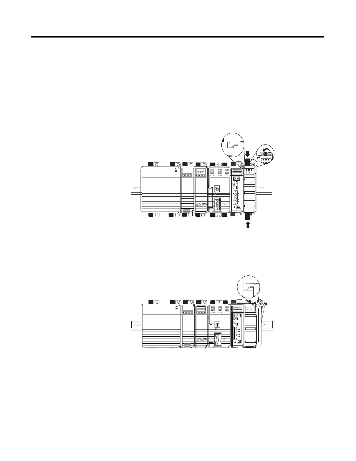
6. Mount the 1769-SDN
b
c
d
b
c
a
and 1769 I/O modules to
the right of the controller
on DIN rail.
In this quick start, the
1769-SDN module is
directly to the right of the
controller in slot 1.
a. Pull locking tabs out.
b. Slide module along
tongue-and-groove
slots on the side of the
controller or modules.
c. Push locking tabs in.
Prepare the CompactLogix Hardware Chapter 1
d. Slide white locking tab
to the left.
A maximum of three
modules can be mounted
between the 1769-SDN
and the power supply.
7. Mount the 1769-ECR
end cap terminator.
a. Pull locking tab to the
right.
b. Slide end cap on rail.
c. Pull locking tab to the
left.
Publication IASIMP-QS003B-EN-P - October 2009 27
Page 28
Chapter 1 Prepare the CompactLogix Hardware
IO_PWR1
IO_COM1
IO_PWR1
IO_COM1
IO_PWR1
IO_COM1
COIL_E1
COIL_E2
ALRM_M
SHIELD
ALRM_B
ALRM_COM
CONSTAT_11
CONSTAT_12
CONSTAT_21
CONSTAT_22
CONSTAT_31
CONSTAT_32
CONSTAT_53
CONSTAT_54
SHIELD
1
3
5
7
9
11
13
15
17
19
21
2
4
6
8
10
12
14
16
18
20
IOL
3
4
24VDC (+)
DC NEUT (-)
CHS GND
Line Interface Module
I/O Power
Front View
8
1
Computer
POINT I/O
connection
PowerFlex 70
connection
PanelView Plus
connection
Ethernet CAT5 Cable
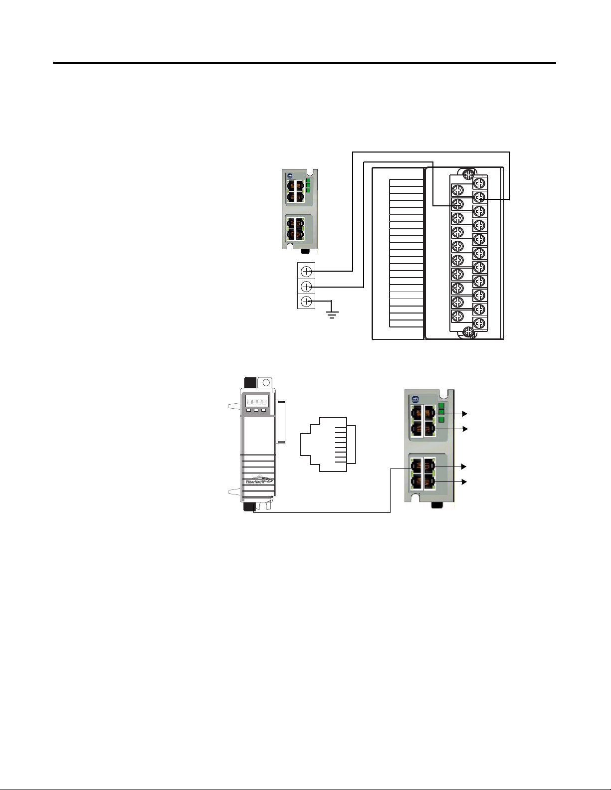
Make EtherNet/IP Network Connection
1. Mount the Ethernet
switch to the DIN rail.
2. Connect the Ethernet
switch power terminals to
the I/O power terminals
on the front of the line
interface module.
3. Connect a CAT5
Ethernet cable between
the Ethernet port on the
bottom of 1768-ENBT
module and the Ethernet
switch.
4. Do not turn on incoming
power.
28 Publication IASIMP-QS003B-EN-P - October 2009
Page 29
Make DeviceNet Network Connections
Input
AC 100-120/200-240V
N L
Isolate power before disconnecting
1606-XL
POWER SUPPLY
DC ok
Output
200W Limited Power
DC 24V / 8A
+ –
DC ok
AC 120V
AC 240V
1. Attach and lock the
1606-XLDNET8
DeviceNet power supply
to a DIN rail by pressing
the tab at the top of the
supply.
Prepare the CompactLogix Hardware Chapter 1
Publication IASIMP-QS003B-EN-P - October 2009 29
Page 30
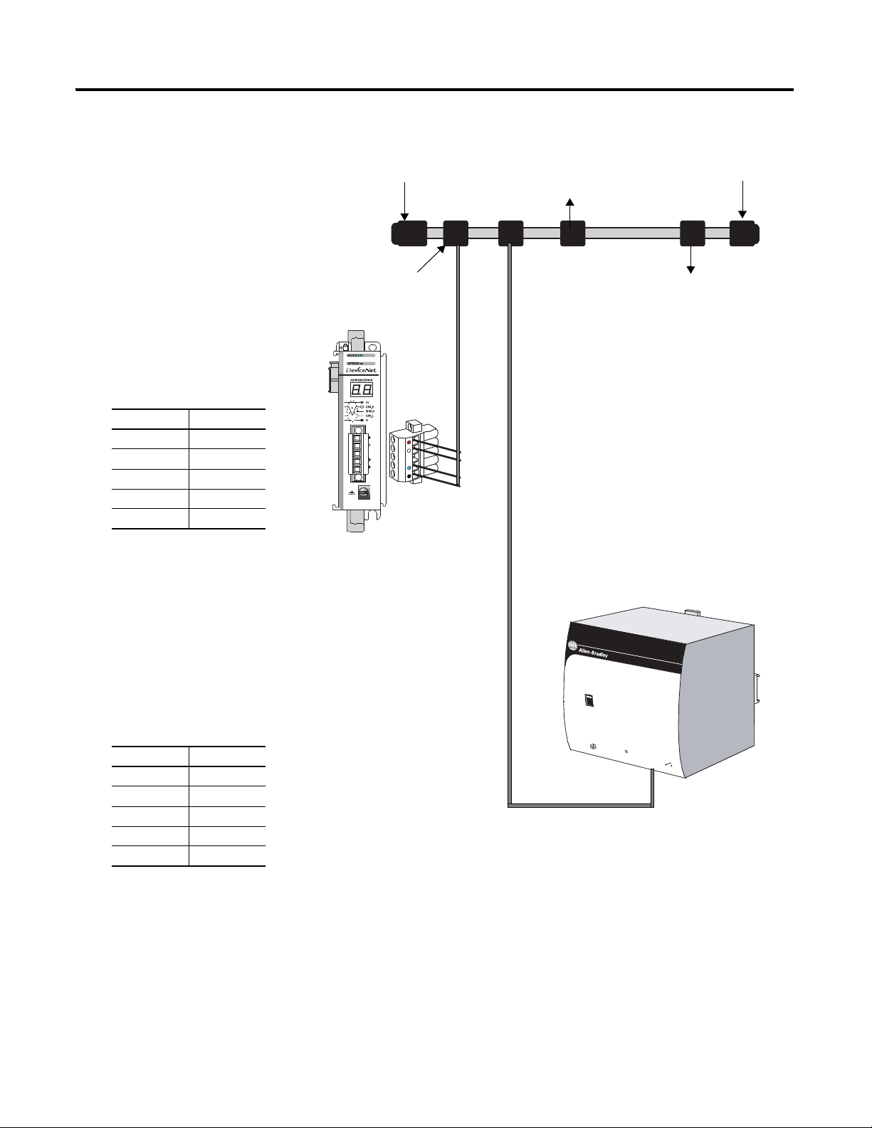
Chapter 1 Prepare the CompactLogix Hardware
PowerFlex 70 Drive
with
20-COMM-D
Distributed
POINT I/O
Connection with
1734-ADN Adapter
1606-XLDNET8
DeviceNet Power Supply
KwikLink Sealed
Terminator
KwikLink Sealed
Terminator
KwikLink Sealed
Micro Connector
2. Assemble the DeviceNet
network cable system
using the KwikLink flat
cable, terminators, and
sealed micro connectors
for each device.
See instructions included
with devices.
3. Wire a KwikLink QD
Micro Cordset to the
1769-SDN connector.
Connect To
Red V+
White CAN High
Bare Shield
Blue CAN Low
Black V-
4. Connect the QD Micro
5. Connect the DeviceNet
6. Connect the DeviceNet
Cordset to a KwikLink
sealed microconnector on
the network.
KwikLink power tap to
the power supply Output
connector.
Connect To
Red +
White Not Used
Shield Not Used
Blue Not Used
Black —
power tap to the
DeviceNet network.
AC 120V
AC 240V
Input
AC 100-120/200-240V
N L
Isolate power before disconnecting
DC ok
1606-XL
POWER SUPPLY
Output
200W Limited Power
DC 24V / 8A
+ –
DC ok
30 Publication IASIMP-QS003B-EN-P - October 2009
Page 31

WARNING
Verify that all incoming power is turned off before wiring power.
Input
AC 100-120/200-240V
N L
Isolate power before disconnecting
1606-XL
POWER SUPPLY
DC ok
Output
200W Limited Power
DC 24V / 8A
+ –
DC ok
AC 120V
AC 240V
Line Interface Module
230V AC AUX Power
Top View
L (line)
N (neutral)
7. Wire the DeviceNet
power supply to the 230V
AC Aux Power Output
connector on the line
interface module.
8. Place the switch in the
position that matches
your supply voltage.
Prepare the CompactLogix Hardware Chapter 1
9. Do not turn on incoming
power.
Publication IASIMP-QS003B-EN-P - October 2009 31
Page 32

Chapter 1 Prepare the CompactLogix Hardware
L1
L2/N
Protective Earth Ground
Line Interface Module
230V AC AUX Power
Top View
Wire the 1768-PA3 Power Supply
Required for EtherNet/IP and DeviceNet Systems
1. Wire the 1768-PA3 power
supply to the 230V AC
Aux Power Output
Connector on the line
interface module.
2. Do not turn on incoming
power.
32 Publication IASIMP-QS003B-EN-P - October 2009
Page 33

Additional Resources
Resource Description
Prepare the CompactLogix Hardware Chapter 1
CompactLogix Controller Installation
Instructions, publication 1768-IN004
CompactLogix EtherNet/IP Communication
Module Installation Instructions, publication
1768-IN002
Compact I/O DeviceNet Scanner Module
Installation Instructions, publication
1769-IN060
Compact Logix SERCOS Interface Module
Installation Instructions, publication
1768-IN005
1768 CompactLogix Power Supply, publication
1768-IN001
KwikLink General Purpose DeviceNet Media
Installation Instructions, publication
1485-IN001
1769 CompactLogix Selection Guide,
publication 1769-SG001
Provides details on how to install controller firmware, configure the serial and
EtherNet/IP driver, and troubleshoot system power and controller operation.
Provides details on how to install, configure and troubleshoot the module.
Provides details on how to install, configure and troubleshoot the module.
Provides information on available fiber optic cables, and details on how to install,
configure and troubleshoot the module.
Provides details on power considerations, master control relay, safety circuits,
grounding, power dissipation, input power requirements, and how to interpret the
status indicators.
Provides details on how to install a DeviceNet network cable system.
Provides details on selecting 1769 CompactLogix system components.
Publication IASIMP-QS003B-EN-P - October 2009 33
Page 34

Chapter 1 Prepare the CompactLogix Hardware
Notes:
34 Publication IASIMP-QS003B-EN-P - October 2009
Page 35

Chapter
2
Prepare the Computer and Load Controller Firmware
Introduction
In this chapter, you configure network communication on your computer and install the
necessary programming and configuration software.
Before You Begin
• Assemble the CompactLogix hardware (Chapter 1).
• Verify that your computer meets the software’s system requirements for your edition of
RSLogix 5000 software.
• Refer to Required Software on page 14
for your system requirements.
What You Need
• Personal computer
• 1756-CP3 serial cable to configure serial driver and update controller firmware
• Ethernet CAT5 cable to configure EtherNet/IP driver (option 1)
• RSLogix 5000 programming software (see page 14
• RSLinx Classic software, version 2.54 or later (packaged with RSLogix 5000
programming software).
• RSNetWorx for DeviceNet software for the DeviceNet network (option 2)
• BOOTP/DHCP server utility (packaged with RSLogix 5000 programming software)
• A Network Interface Card (NIC) and its associated Windows driver installed (the NIC
and driver are standard on most computers)
• An Ethernet Address (MAC) for each device.
• A planned IP Address for each device. If you are using an isolated network, determine a
numbering convention for your IP addresses.
for edition and version information)
• ControlFlash software (packaged with RSLogix 5000 programming software)
35Publication IASIMP-QS003B-EN-P - October 2009 35
Page 36

Chapter 2 Prepare the Computer and Load Controller Firmware
page 52
page 49
page 48
page 46
page 38
Set the IP
Address for
the Computer
Make Network
Connections for
Personal
Terminology
Configure the
EtherNet/IP
Driver in RSLinx
Software
Load the Controller
Firmware
Install Additional
Software
page 37
Install RSLogix
Programming
Configure a
Serial Driver
page 39
page 44
Follow These Steps
Complete the appropriate steps.
36 Publication IASIMP-QS003B-EN-P - October 2009
Page 37

Prepare the Computer and Load Controller Firmware Chapter 2
Terminology
Ethernet networks use these types of addresses.
Term Definition
Ethernet Address Each Ethernet device has a unique Ethernet address (sometimes called a MAC address). The
address appears as twelve digits separated by colons (for example, xx:xx:xx:xx:xx:xx). It is
usually on a label on the device itself.
Each digit is a number in hexadecimal (0 to 9 or A through F). No other device in the world will
have the same address, and it can not be changed.
You use the Ethernet address to identify a device so you can assign it an IP address.
IP Address In addition to the Ethernet address, an IP address identifies a node on an Ethernet network.
The IP address can be manually set. or you can use special software to automatically assign it.
An IP Address consists of four decimal integers separated by periods (xxx.xxx.xxx.xxx). Each xxx
is a decimal value from 0…255. For example, an IP Address could be 192.168.1.092 The
selection of IP Addresses is beyond the scope of this quick start, so please contact your
network administrator or use the ones provided in the examples.
Once you set an IP address for a device, you generally reference the device by its IP address.
The examples in this quick start use IP Addresses to define communication paths to the
devices.
Publication IASIMP-QS003B-EN-P - October 2009 37
Page 38

Chapter 2 Prepare the Computer and Load Controller Firmware
1756-CP3
EtherNet/IP
Serial
Ethernet CAT 5
Serial
1756-CP3
Make Network Connections for Personal Computer
Network Connections Required for EtherNet/IP System
1. Connect a CAT5
Ethernet cable between
the Ethernet port on the
computer and the
Ethernet switch.
This connection is used
to configure the
EtherNet/IP driver in
RSLinx software.
2. Connect the 1756-CP3
cable between the CH0
serial port on the
controller and a computer
COM port.
This connection is used
to configure the serial
driver and load controller
firmware.
Network Connections Required for DeviceNet System
Connect the 1756-CP3 cable
between the CH0 serial port
on the controller and the
COM port on the computer.
This connection is used to
configure the serial driver and
load controller firmware.
38 Publication IASIMP-QS003B-EN-P - October 2009
Page 39

Prepare the Computer and Load Controller Firmware Chapter 2
3. Accept the default
software products for
installation and click
Next.
Throughout the installation, click Next to use default RSLogix 5000 installation settings
except when indicated in the steps below.
1. Begin the RSLogix 5000
software installation.
2. Choose your language and
click Continue.
4. Enter your user name, organization, and
software serial number, then click Next.
Install RSLogix Programming Software
Required for all controllers
Publication IASIMP-QS003B-EN-P - October 2009 39
Page 40

Chapter 2 Prepare the Computer and Load Controller Firmware
7. Select your
activation type
and click Next.
This quick start uses
FactoryTalk
Activation software
to activate RSLogix
5000 software. For
more information,
see the FactoryTalk
Activation FAQ,
publication
Ftalk-FA017.
5. Accept the license agreement and
click Next.
8. Click Next to
install only the
latest version of
RSLogix 5000
software (version
18).
9. Verify that
RSLogix 5000
Tools and Files is
checked and click
Next.
6. Click Next to install the program
files to the default directory.
40 Publication IASIMP-QS003B-EN-P - October 2009
Page 41

10. Click Next to
install the typical
firmware kits.
11. Click Next to install
typical RSLogix
Architect tools.
12. Click Next to install
the typical set of
EDS files and
RSLinx software.
Prepare the Computer and Load Controller Firmware Chapter 2
Publication IASIMP-QS003B-EN-P - October 2009 41
Page 42

Chapter 2 Prepare the Computer and Load Controller Firmware
13. Click Install to
complete the
installation.
The installation
dialog box displays
progress while the
software installs.
TIP
As the installation progresses, you may be prompted to complete additional set-up tasks depending on
your system configuration. Follow those prompts and enter information as indicated in the dialog boxes to
complete your installation.
After a few moments, the
FactoryTalk Installation Wizard
starts.
14. Click Next.
15. Enter the Serial number and
Product key from the
certification letter packaged with
your software.
16. Click Next.
42 Publication IASIMP-QS003B-EN-P - October 2009
Page 43

17. Select your host ID and click
Next.
The activation completes if the
computer is connected to the
Internet.
If Internet access is not
available, call Rockwell
Automation Technical Support
to complete your activation.
18. Click Finish to close the
Activation Wizard.
Prepare the Computer and Load Controller Firmware Chapter 2
Publication IASIMP-QS003B-EN-P - October 2009 43
Page 44

Chapter 2 Prepare the Computer and Load Controller Firmware
1. Launch RSLinx
software.
2. Under Communications, select Configure
Drivers.
3. Select RS-232 DF1 devices.
4. Click Add New.
5. Click OK to keep the default
name.
Configure a Serial Driver
Required for all controllers
44 Publication IASIMP-QS003B-EN-P - October 2009
Page 45

The Serial driver is added to the
Configured Drivers list.
10. Verify that the Status of the driver
is Running, and click Close.
11. Click the RSWho icon to view
the driver.
All of the configured, active drivers
display.
6. Select the Comm Port to which you
connected the 1756-CP3 cable.
7. For Device, select
Logix5550/CompactLogix.
8. Click Auto Configure.
9. Click OK.
Expand the serial driver to see
connected devices.
Prepare the Computer and Load Controller Firmware Chapter 2
Publication IASIMP-QS003B-EN-P - October 2009 45
Page 46

Chapter 2 Prepare the Computer and Load Controller Firmware
1. On your desktop, right-click My
Network Places and select
Properties.
2. Double-click the Local Area
Connection.
3. Click Properties.
4. On the General tab, select Internet
Protocol (TCP/IP) and click
Properties.
5. Select Use the following IP address
and enter an IP address and Subnet
mask for your computer using the
example shown or enter your own
address.
For more information about selecting
an IP Address, see page 7-81
.
6. Click OK.
7. Record the IP address and subnet mask in the Network Worksheet on the back cover.
8. Click OK.
Set the IP Address for the Computer
Required for all controllers, regardless of network choice
46 Publication IASIMP-QS003B-EN-P - October 2009
Page 47

9. Click the Support tab.
10. Verify that the IP Address and Subnet
Mask match what you entered on the
Appendix A.
If these numbers do not match what
you entered, contact your network
administrator to verify that your IP
address is correct.
11. Close the Local Area Connection
Status dialog box.
Prepare the Computer and Load Controller Firmware Chapter 2
Publication IASIMP-QS003B-EN-P - October 2009 47
Page 48

Chapter 2 Prepare the Computer and Load Controller Firmware
1. If RSLinx software is not open, launch RSLinx software.
2. From the Communications
menu, choose Configure
Drivers.
3. From the Available
Driver Types, select
Ethernet/IP Driver.
4. Click Add New.
5. Click OK to keep the default
name.
6. Click OK to Browse Local
Subnet.
Configure the EtherNet/IP Driver in RSLinx Software
Required for 1768-L43, 1768-L45, and PanelView Plus
48 Publication IASIMP-QS003B-EN-P - October 2009
Page 49

Load the Controller Firmware
TIP
The EtherNet/IP driver is
added to the Configured
Drivers list.
7. Verify that the driver’s
Status is Running, and click
Close.
Prepare the Computer and Load Controller Firmware Chapter 2
Required for All Systems
This procedure shows how to load firmware in the controller using a serial connection. It is faster to load
the firmware using an EtherNet/IP connection. For details, see the controller installation instructions.
1. Turn on incoming power
to the CompactLogix
power supply.
2. Launch the ControlFlash
software.
Publication IASIMP-QS003B-EN-P - October 2009 49
Page 50

Chapter 2 Prepare the Computer and Load Controller Firmware
18.0
3. Click Next when the
Welcome screen appears.
4. Select the controller
catalog number and click
Next.
5. Move the keyswitch on
controller to Program.
6. If the Current Revision
matches the firmware
revision you want, click
Cancel, then skip to the
next section.
Otherwise, select the
revision level to which
you want to update the
controller and click Next.
If you are not sure what
revision to use, select the
latest.
50 Publication IASIMP-QS003B-EN-P - October 2009
Page 51

7. Click Finish, then click
18.0
ATTENTION
Yes to start the firmware
update.
When the controller is
updated, the status box
displays Update
complete.
8. Close ControlFlash by
clicking Cancel, then Yes.
Prepare the Computer and Load Controller Firmware Chapter 2
The 1768-L43 and 1768-L45 controllers are compatible with firmware version 16.23, or
later. If you encounter errors, contact Technical Support.
Publication IASIMP-QS003B-EN-P - October 2009 51
Page 52

Chapter 2 Prepare the Computer and Load Controller Firmware
Install Additional Software
• If your network configuration includes a PanelView Plus terminal, install FactoryTalk
Machine Edition software and RSLinx Enterprise software from the FactoryTalk View
Machine Edition package.
• If you are using a DeviceNet network, install RSNetWorx for DeviceNet software. Also
install the DeviceNet Tag Generator Tool under optional steps of the RSNetWorx for
DeviceNet install.
Additional Resources
Resource Description
CompactLogix Controller Installation
Instructions 1768-IN004
Provides other methods for loading firmware in the controller.
FactoryTalk Activation FAQ, publication
FTalk-FA017
ControlFlash Firmware Upgrade Kit, publication
1756-QS105
Provides answers to FactoryTalk Activation questions, including how the FactoryTalk
Activation differs from master disk activation.
Provides details regarding the installation of ControlFlash software and execution of
firmware upgrades.
52 Publication IASIMP-QS003B-EN-P - October 2009
Page 53

Chapter
Prepare the Distributed POINT I/O Hardware
Introduction
In this chapter, you install the 1734 POINT network adapter and the 1734 POINT I/O
modules.
Before You Begin
• Assemble your CompactLogix hardware (Chapter 1).
3
• Determine which of these network adapters to use:
– For an EtherNet/IP network (option 1), use the 1734-AENT adapter.
– For an DeviceNet network (option 2), use the 1734-ADN adapter.
• Select the appropriate mounting base for the I/O modules:
– For the 1734-IT2I module, use the 1734-TBCJC mounting base
– For all other modules, use the 1734-TB or 1734-TBS mounting base.
What You Need
• POINT I/O adapter: 1734-AENT or 1734-ADN
• POINT I/O mounting bases: 1734-TB or 1734-TBS, and 1734-TBCJC
• A digital POINT I/O module. This example uses 1734-OB4E, however, other POINT
I/O modules can also be used but are not required.
• 1794-PS3 or 1794-PS13 power supply
• DIN rail
• Standard CAT5 Ethernet cable for EtherNet/IP system (option 1)
53Publication IASIMP-QS003B-EN-P - October 2009 53
Page 54

Chapter 3 Prepare the Distributed POINT I/O Hardware
page 59
page 58
page 57
page 56
page 59
page 58
page 57
Mount and
Connect the
Network Adapter
Mount the POINT
I/O Modules
Mount and Wire
the POINT I/O
Power Supply
Wire the Adapter
and I/O Modules to
the Power Supply
page 55
Mount and
Connect the
Network Adapter
Mount the POINT
I/O Modules
Mount and Wire
the POINT I/O
Power Supply
Wire the Adapter
and I/O Modules to
the Power Supply
EtherNet/IP
DeviceNet
Distributed POINT I/O
Power
Supply
Follow These Steps
If you have POINT I/O, complete the steps for your network.
DIRTY
L1 L2 L3 E
LINE
DIRTY
LOAD
L1 L2 L3 E
DIRTY
DIRTY
CLEAN
CLEAN
CLEAN
CD V4
2
rewoP
O
YLPPU
W
S RE
P
971
3SP-4
MOC
V42
CLEAN
54 Publication IASIMP-QS003B-EN-P - October 2009
Page 55

Prepare the Distributed POINT I/O Hardware Chapter 3
00:00:BC:21:44:8A
Ethernet Address
p
E
t
h
e
r
n
e
t
A
d
d
r
e
s
s
Example Address
Mount and Connect the Network Adapter
1734-AENT EtherNet/IP Adapter for EtherNet/IP System
1. Locate the Ethernet
Address (MAC) and the
major revision on the
POINT Adapter and
record both in Appendix
A.
The address is used to set
the IP address.
2. Set the address to a value
greater than or equal to
256.
This example uses 999.
3. Remove the protective
cover from the right side
of the adapter.
4. Press the adapter onto
the DIN rail.
5. Connect an Ethernet
cable between the
Ethernet connector on
the adapter and the
Ethernet switch.
For EtherNet/IP
systems, skip to page 57
Mount the Point I/O
Modules.
,
Publication IASIMP-QS003B-EN-P - October 2009 55
Page 56

Chapter 3 Prepare the Distributed POINT I/O Hardware
retpad
A
suta
t
S
teNeciveD
sutat
S
suBtnioP
s
utat
S
NDA-4371
dleiF
rewoP
m
e
tsyS
rewoP
PowerFlex 70 Drive
with
20-COMM-D
KwikLink Sealed
Terminator
KwikLink Sealed
Terminator
KwikLink Sealed
Micro Connector
1769-SDN
DeviceNet Module
1606-XLDNET8
Power Supply
1734-ADN DeviceNet Adapter for DeviceNet System
1. Remove the protective
cover from the right side
of the adapter.
2. Press the adapter onto
the DIN rail.
3. Set the node address to
02 for this example.
4. Wire the KwikLink QD
Micro Cordset to the
1734-ADN connector.
Connect To
Red V+
White CAN High
Bare Shield
Blue CAN Low
Black V-
5. Connect the QD Micro
Cordset to a KwikLink
sealed micro connector
on the DeviceNet
network.
56 Publication IASIMP-QS003B-EN-P - October 2009
Page 57

Mount the POINT I/O Modules
IMPORTANT
Wiring Base
Tongue-and-groove slots
Handle
Module
Required for EtherNet/IP and DeviceNet Systems
The 1734-IT21 must be mounted in the 1734-TBCJC wiring base. All other
modules can be mounted in either the 1734-TB or 1734-TBS wiring bases.
1. Using a small, flathead
screwdriver, rotate the
keyswitch on the wiring
base to 1.
Prepare the Distributed POINT I/O Hardware Chapter 3
This quick start uses the
1734-OB4E output
module.
2. Press the module into the
wiring base.
3. Snap the handle up.
4. Complete steps 1-3 with
all POINT I/O modules.
5. Slide the first module and
wiring base assembly
along the side of the
adapter and press it onto
DIN rail.
6. Repeat with all of the I/O
assemblies.
2
3
1
4
8
7
1
5
6
Publication IASIMP-QS003B-EN-P - October 2009 57
Page 58

Chapter 3 Prepare the Distributed POINT I/O Hardware
WARNING
Upper-lip of DIN rail latch
GR
L2/N
L1
L2
L1
Optional LIM 230V AC
AUX Power Output Connector
Top View
Mount and Wire the POINT I/O Power Supply
1794-PS3 or 1794-PS13 Power Supply for EtherNet/IP and DeviceNet Systems
Verify that all incoming power is turned off before wiring power.
1. Hook the upper-lip of the
power module onto the
DIN rail.
2. Press the module onto
the DIN rail.
3. Wire the POINT I/O
power supply to the 230V
AC Aux Power Output
connector on the line
interface module.
58 Publication IASIMP-QS003B-EN-P - October 2009
Page 59

Prepare the Distributed POINT I/O Hardware Chapter 3
COM
24V
Wire the Adapter and I/O Modules to the Power Supply
Required for EtherNet/IP and DeviceNet Systems
1. Connect the 12/24V dc
common and power wires
from the power supply to
the adapter.
Refer to the installation
instructions for the
1734-AENT or
1734-ADN adapters.
2. Refer to the individual
POINT I/O installation
instructions for wiring
the I/O modules.
3. Turn on incoming power.
Publication IASIMP-QS003B-EN-P - October 2009 59
Page 60

Chapter 3 Prepare the Distributed POINT I/O Hardware
Additional Resources
Resource Description
POINT I/O EtherNet/IP Adapter Installation
Instructions, publication 1734-IN590
POINT I/O DeviceNet Adapter Installation
Instructions, publication 1734-IN026
POINT I/O Wiring Base Assembly Installation
Instructions, publication 1734-IN511
POINT I/O Cold Junction Compensation Wiring
Base Assembly Installation Instructions,
publication 1734-IN583
POINT I/O Protected Output Module Installation
Instructions, publication 1734-IN056
FLEX I/O DC Power Supply Module Installation
Instructions, publication 1794-IN069
Point I/O Selection Guide, publication
1734-SG001
Provides details regarding installation of the adapter and technical specifications.
Provides details regarding installation of the adapter and technical specifications.
Provides details on how to install and remove the wiring base, and terminal block.
Provides details regarding installation of the Cold Junction Compensated Terminal
Block wiring base.
Provides details on how to install, wire, communicate with, and troubleshoot the
protected output module.
Provides details on how to mount and wire the power supply.
Provides details on selecting 1734 POINT I/O components.
60 Publication IASIMP-QS003B-EN-P - October 2009
Page 61

Chapter
4
Prepare the PowerFlex 70 Drive
Introduction
In this chapter, you mount and wire power to a PowerFlex 70 drive. You also configure the
communication adapter and make network connections.
Before You Begin
• Assemble your CompactLogix hardware (Chapter 1).
• Determine which network adapter to use on the PowerFlex 70 drive:
– For an EtherNet/IP network (option 1), use the 20-COMM-E adapter.
– For a DeviceNet network (option 2), use the 20-COMM-D adapter.
What You Need
• PowerFlex 70 drive
• PowerFlex 70 communication adapter
– 20-COMM-E for an EtherNet/IP network (option 1)
– 20-COMM-D for a DeviceNet network (option 2)
• Standard CAT5 Ethernet cable for EtherNet/IP system (option 1)
61Publication IASIMP-QS003B-EN-P - October 2009 61
Page 62

Chapter 4 Prepare the PowerFlex 70 Drive
page 65
page 65
DIRTY
DIRTY
CLEAN
CLEAN
CLEAN
DIRTY
CLEAN
DIRTY
L1 L2 L3 E
L1 L2 L3 E
LINE
LOAD
rewoP
CD V4
2
YLPPU
S RE
W
O
P
3SP-4
971
V42
MOC
page 67
page 63
Connect
Communication
Adapter to the
PowerFlex 70 Drive
Configure the
Communication
Adapter
Mount and Wire
the PowerFlex 70
Drive
page 66
page 63
Connect
Communication
Adapter to the
PowerFlex 70 Drive
Configure the
Communication
Adapter
Mount and Wire
the PowerFlex 70
Drive
EtherNet/IP
DeviceNet
Follow These Steps
If you have a PowerFlex 70 Drive, complete the steps for your network.
62 Publication IASIMP-QS003B-EN-P - October 2009
Page 63

Mount and Wire the PowerFlex 70 Drive
WARNING
Required for EtherNet/IP and DeviceNet Systems
Verify that all incoming power is turned off before wiring power.
1. Mount the PowerFlex 70
drive to the control
enclosure subpanel using
the four mounting slots
provided.
Prepare the PowerFlex 70 Drive Chapter 4
For mounting
instructions, refer to the
PowerFlex 70 User
Manual, publication
20A-UM001.
2. Loosen the screw and
remove the cover.
Publication IASIMP-QS003B-EN-P - October 2009 63
Page 64

Chapter 4 Prepare the PowerFlex 70 Drive
L1RL2SL3TBR1
+DC
BR2
BRKT1UT2VT3W
PE PE
Optional LIM 240V AC
3-Phase Load Connector
Motor
fuse
fuse
fuse
Top View
3. Remove a knockout from
the bottom plate on the
drive for routing the
power line conductors.
4. Wire the PowerFlex 70
240V AC, 3-phase line
power terminals to the
240V AC, 3-phase Load
connector on the line
interface module.
Fuse according to
PowerFlex power rating.
5. Wire the PE Chassis
ground terminal on the
PowerFlex 70 to earth
ground.
6. Connect the 240V
3-phase motor to the
PowerFlex T1, T2, T3,
PE terminals.
64 Publication IASIMP-QS003B-EN-P - October 2009
Page 65

Configure the Communication Adapter
2
1
0
9
8
3
4
5
6
7
2
1
0
9
8
3
4
5
6
7
Tens
Digit
Ones
Digit
PGM
500K
250K
125K
AUTO
HW Address 00:00:BC:32:00:35
For example:
20-COMM-D DeviceNet Adapter for DeviceNet System
1. Set the node address on
the adapter to 13 for this
quick start.
2. Set the adapter to AUTO
for autobaud.
Prepare the PowerFlex 70 Drive Chapter 4
20-COMM-E EtherNet/IP Adapter for EtherNet/IP System
Locate the Ethernet Address
(MAC) on the label of the
adapter and record this
address in Appendix A
This address is used to set the
IP address.
.
Publication IASIMP-QS003B-EN-P - October 2009 65
Page 66

Chapter 4 Prepare the PowerFlex 70 Drive
POINT I/O with
1734-ADN Adapter
KwikLink Sealed
Terminator
KwikLink Sealed
Terminator
KwikLink Sealed
Micro Connector
1606-XLDNET8
Power Supply
1769-SDN
DeviceNet Module
Connect Communication Adapter to the PowerFlex 70 Drive
20-COMM-D DeviceNet Adapter for DeviceNet System
1. Connect the flat-ribbon
cable between the adapter
and the PowerFlex 70
drive.
2. Fold the cable under
adapter without creasing
and secure adapter on
drive using the captive
screws.
3. Remove a knockout from
4. Wire the KwikLink QD
5. Connect the QD Micro
the bottom plate on the
drive and route the
DeviceNet network cable
through the hole.
Micro Cordset to the
20-COMM-D connector.
Connect To
Red V+
White CAN High
Bare Shield
Blue CAN Low
Black V-
Cordset to a KwikLink
sealed micro connector
on the DeviceNet
network.
6. Replace drive cover.
66 Publication IASIMP-QS003B-EN-P - October 2009
Page 67

20-COMM-E EtherNet/IP Adapter for EtherNet/IP System
1. Connect the flat-ribbon
cable between the adapter
and the PowerFlex 70
drive.
2. Fold the cable under the
adapter without creasing
and secure the adapter on
the drive using the captive
screws.
Prepare the PowerFlex 70 Drive Chapter 4
3. Remove a knockout from
the bottom plate on the
drive route the Ethernet
cable through the hole.
4. Connect a CAT5
Ethernet cable between
the Ethernet adapter and
the Ethernet switch.
5. Replace drive cover.
Publication IASIMP-QS003B-EN-P - October 2009 67
Page 68

Chapter 4 Prepare the PowerFlex 70 Drive
Additional Resources
Resource Description
PowerFlex 70 User Manual, publication
20A-UM001
PowerFlex 70 EtherNet/IP Adapter User
Manual, publication 20COMM-UM010
PowerFlex 70 DeviceNet Adapter User Manual,
publication 20COMM-UM002
Provides details on how to mount and wire power to the PowerFlex 70 drive. Also
provides information on how to set drive parameters and troubleshoot the drive.
Provides details on how to install, configure, and use the adapter.
Provides details on how to install, configure, and use the adapter.
68 Publication IASIMP-QS003B-EN-P - October 2009
Page 69

Chapter
5
Prepare the PanelView Plus Terminal
Introduction
In this chapter, you mount and wire the PanelView Plus terminal. You also configure network
communication and make network connections.
Before You Begin
• Assemble your CompactLogix hardware (Chapter 1).
• Determine which network to use.
– EtherNet/IP network (option 1) using Ethernet connection
– DeviceNet network (option 2) using serial connection
What You Need
• PanelView Plus terminal
• Standard CAT5 Ethernet cable for Ethernet connection (option 1)
• 2711-NC13 cable for a serial connection
69Publication IASIMP-QS003B-EN-P - October 2009 69
Page 70

Chapter 5 Prepare the PanelView Plus Terminal
page 72
page 71
page 73
page 72
page 71
Mount and Wire
the PanelView
Plus Terminal
Make Network
Connections for
PanelView Plus
Assign IP Address
for PanelView Plus
EtherNet/IP
Mount and Wire
the PanelView
Plus Terminal
Make Network
Connections for
PanelView Plus
DeviceNet
Follow These Steps
If you have a PanelView Plus terminal, complete the appropriate steps.
70 Publication IASIMP-QS003B-EN-P - October 2009
Page 71

Prepare the PanelView Plus Terminal Chapter 5
WARNING
24V (+)
COM (-)
Line Interface Module I/O Power
Front View
Mount and Wire the PanelView Plus Terminal
Required for EtherNet/IP and DeviceNet Systems
For the purpose of this quick start, the PanelView Plus terminal can be propped on a desktop.
For complete mounting instructions, refer to the PanelView Plus Terminal user manual,
publication 2711P-UM001
Verify that all incoming power is turned off before wiring power.
.
1. Mount the PanelView
Plus to the control
enclosure door using the
mounting clips shipped
with terminal.
2. Remove the terminal
block from the
PanelView Plus.
3. Connect the PanelView
Plus power terminal
block to the I/O power
terminals on the front of
the line interface module.
4. Re-attach the terminal
block to the PanelView
Plus terminal.
2
4
6
8
10
12
14
16
18
20
IO_PWR1
1
IO_COM1
IO_PWR1
3
IO_COM1
IO_PWR1
5
IO_COM1
COIL_E1
7
COIL_E2
ALRM_M
9
SHIELD
ALRM_B
11
ALRM_COM
CONSTAT_11
13
CONSTAT_12
CONSTAT_21
15
CONSTAT_22
CONSTAT_31
17
CONSTAT_32
CONSTAT_53
19
CONSTAT_54
SHIELD
21
-
IOL
+
1
2
Publication IASIMP-QS003B-EN-P - October 2009 71
Page 72

Chapter 5 Prepare the PanelView Plus Terminal
CAT5 Ethernet Cable
2711-NC13
Make Network Connections for PanelView Plus
Network Connections Required for EtherNet/IP System
Connect a CAT5 Ethernet
cable between the Ethernet
port on the PanelView Plus
terminal and the Ethernet
switch.
Network Connections Required for DeviceNet System
Connect the 2711-NC13
cable between the serial port
on the PanelView Plus
terminal and the CH0 serial
port of the L43 controller.
72 Publication IASIMP-QS003B-EN-P - October 2009
Page 73

Assign IP Address for PanelView Plus
Networks and Communications
Network Connections
Network Adapters
Built-in Ethernet Controller
Diagnostics Setup
Display
File Management
Font Linking
Input Devices
Networks and Communications
Print Setup
Startup Options
System Event Log
System Information
Time/Date/Regional Settings
Required for EtherNet/IP System
1. Apply power to the
PanelView terminal.
2. On the initial PanelView
configuration screen,
select Terminal Settings
[F4].
3. Navigate to
Built-in Ethernet
Controller by selecting
Prepare the PanelView Plus Terminal Chapter 5
the path shown.
4. Select IP Address [F2].
Publication IASIMP-QS003B-EN-P - October 2009 73
Page 74

Chapter 5 Prepare the PanelView Plus Terminal
5. Select Use DHCP [F4] to
select No.
6. Select IP Address [F1].
a. Enter an IP address in
the input panel.
b. Press Enter.
c. Record IP address in
Appendix A.
For information on IP
addresses, see page 89
.
7. Select Subnet Mask [F2].
a. Enter the subnet mask
for your computer,
recorded in Appendix
A.
b. Press Enter.
8. Select OK [F7] to save
settings, then OK [F7]
again to acknowledge
reset message.
74 Publication IASIMP-QS003B-EN-P - October 2009
Page 75

9. Select Close [F8] until
you return to the initial
configuration screen.
10. Select Reset [F8] to reset
the terminal, then
Yes [F7] to confirm.
Prepare the PanelView Plus Terminal Chapter 5
Upgrade Terminal Firmware
Required for Terminals with Firmware Earlier than 4.00.09
If the firmware in your PanelView Plus terminal is earlier than 4.00.09, you need to upgrade
the terminal firmware. You can download the firmware from this website:
http://support.rockwellautomation.com/ControlFlash/FUW.asp
To update the terminal firmware, launch FactoryTalkView Machine Edition software and
select Tools>Firmware Upgrade Wizard. Upgrade the firmware in the terminal by using the
RSLinx Enterprise network connection.
Publication IASIMP-QS003B-EN-P - October 2009 75
Page 76

Chapter 5 Prepare the PanelView Plus Terminal
Additional Resources
Resource Description
PanelView Plus Terminal User Manual,
publication 2711P-UM001
PanelView Plus Grounding and Wiring
Applications Technical Data, publication
2711P-TD001
Provides details on how to install communication modules, mount the PanelView Plus
terminals, wire power to the terminals, make network connections, and configure
terminal settings.
Provides comprehensive guidelines on how to properly ground and wire PanelView Plus
terminals.
76 Publication IASIMP-QS003B-EN-P - October 2009
Page 77

Chapter
6
Prepare the Kinetix 6000 Multi-axis Servo Drive System
Introduction
In this chapter, you prepare your Kinetix 6000 Multi-axis Servo Drive system.
Before You Begin
• Assemble your CompactLogix Hardware (Chapter 1)
• Review Basic System Components (Preface
)
What You Need
• Input Power: Line Interface Module (optional), line filter
• Kinetix 6000 Multi-axis Servo Drive System: power rail, Axis and Integrated Axis
Modules
• Motors
• Cables: motor power, motor feedback, SERCOS fiber optic cables, connector kit
77Publication IASIMP-QS003B-EN-P - October 2009 77
Page 78

Chapter 6 Prepare the Kinetix 6000 Multi-axis Servo Drive System
page 80
page 83
page 82
page 79
Mount and Bond
the Power Rail
page 80
Mount the
Integrated Axis and
Axis Module
Wire Power to the
Integrated Axis
Module
Wire Servo Motors
to Integrated Axis
and Axis Modules
page 84
Connect the
SERCOS Fiber
Optic Cables
Set the SERCOS
Node Address
page 85
Line Interface
Module
AC Line
Filter
Follow These Steps
If you have a Kinetix 6000 Multi-axis Servo Drive System, complete these steps.
DIRTY
L1 L2 L3 E
LINE
CLEAN
LOAD
L1 L2 L3 E
DIRTY
CLEAN
DIRTY
DIRTY
CLEAN
CD V4
2
rewoP
O
YLPPU
W
S RE
P
971
3SP-4
MOC
V42
CLEAN
78 Publication IASIMP-QS003B-EN-P - October 2009
Page 79

Prepare the Kinetix 6000 Multi-axis Servo Drive System Chapter 6
Boot
Ground Stud
with Braided
Ground Strap
Bonded
Cabinet
Ground
Mount and Bond the Power Rail
2094-PRS1 through 2094-PRS8
The Kinetix power rails support one integrated axis module (IAM), and up to seven axis
modules (AM), or shunt modules (SM). The connector pins for each slot on the power rail are
covered by a protective boot. Do not remove the protective boot until you install the
modules.
1. Layout the position for
your power rail in the
enclosure.
2. Attach the power rail to
the cabinet using M6 (1/4
in.) bolts, making sure the
power rail is properly
bonded to the cabinet.
3. Bond the power rail to
the enclosure subpanel
using the ground strap
provided.
4. Tighten all mounting
fasteners.
Publication IASIMP-QS003B-EN-P - October 2009 79
Page 80

Chapter 6 Prepare the Kinetix 6000 Multi-axis Servo Drive System
Guide Pin
Guide
Pin Holes
Power Rail
Typical Rear View of
IAM or AM Module
Mount the Integrated Axis and Axis Module
2094-AC09-M02, 2094-AM01
The integrated axis module (IAM) mounts in the two leftmost slots of the power rail. The
axis modules (AM) mount to the right of the IAM module in left-to-right order, ranging from
highest-to-lowest power rating. This quick start uses one integrated axis module and one axis
module. Slot filler modules fill the remaining empty slots on the power rail. If your
application includes a shunt module, it would mount to the right of the axis modules.
1. Remove the protective
boot covering the two
leftmost slots on the
power rail.
2. Remove the label from
the IAM module
(2094-AC09-M02) that is
covering the power
connector pins.
3. Hang the mounting
bracket from the slots on
the power rail.
4. Pivot the IAM module
downward, aligning the
guide pins on the power
rail with the guide pin
holes on the back of the
module.
5. Gently push the module
against the power rail.
80 Publication IASIMP-QS003B-EN-P - October 2009
Page 81

6. Use 2.26 Nm (20 lb•in)
Mounting Screws on IAM and AM modules.
torque to tighten the
mounting screws.
7. Remove the protective
boot from the power rail
slot to the right of the
IAM module.
Prepare the Kinetix 6000 Multi-axis Servo Drive System Chapter 6
8. Repeat steps 2 through 6
to mount the AM module
in the power rail slot to
the right of the IAM
module.
9. Repeat steps 2 through 6
to mount slot filler
modules in all remaining,
empty power slots.
Publication IASIMP-QS003B-EN-P - October 2009 81
Page 82

Chapter 6 Prepare the Kinetix 6000 Multi-axis Servo Drive System
Line Interface Module
AC RFI
Line
Filter
E-Stop
Top View
Integrated Axis Module
Front View
Top View
5
1
2
5
4
3
Incoming Power
Wire Power to the Integrated Axis Module
This procedure shows power connections to the integrated axis module (IAM) when using
the line interface module (LIM). The AC conductor sizes are based on the motor load
requirements.
2094-AC09-M02
1. Wire the LIM module
2. Wire the AC line filter
3. Wire the 230V control
load terminals to the AC
line filter, line terminals.
load terminals to the IAM
line terminals.
power from the LIM to
the IAM module.
L3
L2
L1
L3
L2
L1
195-265 VAC LINE, 50/60 Hz
L3'
L2'
L1'
195-265 VAC LOAD, 50/60 Hz
1 2 3 4
1 2 3 4
CL2
CL1
IOL
IO_PWR1
1
2
IO_COM1
CONTROL VAC
IO_PWR1
CTRL2
1 2
CTRL1
AUX2
AUX2
AUX1
AUX1
1 2 3 4
I/O_COM
I/O_PWR
I/O_COM
I/O_PWR
I/O_COM
I/O_PWR
1 2 3 4 5 6
3
4
IO_COM1
IO_PWR1
5
6
IO_COM1
230 VAC SUPPLY
COIL_E1
7
8
COIL_E2
ALRM_M
9
10
SHIELD
ALRM_B
11
12
ALRM_COM
24 VDC SUPPLY
CONSTAT_11
13
14
CONSTAT_12
CONSTAT_21
15
16
CONSTAT_22
CONSTAT_31
17
18
CONSTAT_32
CONSTAT_53
19
20
CONSTAT_54
SHIELD
21
6
8
1
7
4. Wire the E1 safety coil on
the LIM module to the
E-stop button.
5. Wire the E2 safety coil on
LIM module to the
CONT EN contacts on
the IAM module.
L1 L2 L3 E
LINE
LOAD
L1 L2 L3 E
1 2
CTRL 2
CTRL 1
1 2 3 4 5 6
DCDC+
L3
L2
L1
1 2
CONT ENCONT EN+
1 2 3 4 5 6 7 8 9
RX
DPI
MBRK MBRK +
DBRK DBRK +
W
V
1 2 3 4
U
COM
PWR
1 2 3 4 5 6
TX
BAUD
RATE
82 Publication IASIMP-QS003B-EN-P - October 2009
Page 83

Prepare the Kinetix 6000 Multi-axis Servo Drive System Chapter 6
U-Brown
V-Black
W-Blue
Green/Yellow
BAUD
RATE
TX
RX
DPI
DCDC+
L3
L2
L1
CONT ENCONT EN+
CTRL 2
CTRL 1
W
V
U
MBRK -
MBRK +
COM
PWR
DBRK -
DBRK +
1 2 3 4
MP
MF
Top View
Front View
Integrated Axis Module or Axis Module
MPL Motor
Motor Feedback Cable
2090-UXNFBMP-S03
Motor Power Cable
2090-XXNPMP-16S03
1
2
3
Wire Servo Motors to Integrated Axis and Axis Modules
2094-AC09-M02, 2094-AM01, MPL-A310P-MK22AA, 2090-XXNPMP-16S03, 2090-UXNFBMP-S03
1. Attach motor power
cable to shield clamp.
a. Use a small flatblade
screwdriver to depress
the spring loaded
clamp plate.
Cable
Tie Wrap
b. Position the exposed
braid of the motor
power cable in line with
the clamp.
c. Release the spring,
making sure the cable
and braid are secured
by clamp.
d. Attach the tie wrap
around cable and
clamp if you need more
strain relief.
2. Connect the motor power
cable between the Motor
Power (MP) Connector
on the IAM or AM
module and the power
Cable Clamp
Exposed Braid
under Clamp
connector on the motor.
3. Connect the feedback
cable between the Motor
Feedback (MF) connector
on the IAM or AM
module and the feedback
connector on the motor.
4. Repeat steps 1 through 3
for all servo motors and
AM modules.
Publication IASIMP-QS003B-EN-P - October 2009 83
Page 84

Chapter 6 Prepare the Kinetix 6000 Multi-axis Servo Drive System
SERCOS Interface Module
SERCOS Interface Module, 1768-M04SE
Connect the SERCOS Fiber Optic Cables
2090-SCEP0-1, 2090-SCEP0-9
1. Connect the
2090-SCEP0-9 fiber optic
cable between the TX
port on the bottom of the
SERCOS module and the
RX port on the IAM
module, making sure to
tighten the fiber optic
ring on each end.
2. Connect the
2090-SCEP0-9 fiber optic
cable between the RX
port on the bottom of the
SERCOS module and the
TX port on the AM
module, making sure to
tighten the fiber optic
ring on each end.
3. Connect the
2090-SCEP0-1 fiber optic
cable between the TX
port on the IAM module
SERVO
Interface
b
a
c
2090-SCEP0-9
31604-M
TX
RX
SERCOS FIBER-OPTIC RING
2090-SCEP0-1
2090-SCEP0-9
TXRXTXRX
and the RX port on the
AM module, making sure
to tighten the fiber optic
ring on each end.
84 Publication IASIMP-QS003B-EN-P - October 2009
AXIS 0 AXIS 1
KINETIX 2 AXIS MOTION
NODE 03NODE 01
Page 85

Set the SERCOS Node Address
1
0
1. Set the SERCOS node
address on the front of
the Integrated Axis
Module to 01.
Prepare the Kinetix 6000 Multi-axis Servo Drive System Chapter 6
2. Record this address in
Appendix A
.
Publication IASIMP-QS003B-EN-P - October 2009 85
Page 86

Chapter 6 Prepare the Kinetix 6000 Multi-axis Servo Drive System
Additional Resources
Resource Description
Kinetix Motion Control Selection Guide,
publication GMC-SG001
Kinetix 6000 Multi-Axis Servo Drive Installation
Manual, publication 2094-IN001
Kinetix 6000 Multi-Axis Servo Drive User
Manual, publication 2094-UM001
Line Interface Module installation Instructions,
publication 2094-IN005
System Design for Control of Electrical Noise,
publication GMC-RM001
Kinetix Accelerator Toolkit Quick Start,
publication IASIMP-QS002
Logix5000 Motion Modules User Manual,
publication LOGIX-UM002
System Design for Control of Electrical Noise
Video, publication GMC-SP004
Kinetix Accelerator Toolkit CD, IASIMP-SP004
Provides details on motor and drive performance specifications.
Provides details on panel layout, and how to install and wire Kinetix 6000 drives and
components.
Provides details on how to integrate your Kinetix 6000 system with a CompactLogix
2094-M04SE SERCOS module, including how to start up, configure, and troubleshoot
the system.
Provides details on how to install, wire, and troubleshoot the line interface module.
Provides best practices on how to minimize noise in control panel while complying with
noise regulations.
Provides complete details and tools to help you quickly integrate a Kinetix Motion
system into your ControlLogix system.
Provides details on how to setup and configure motion control using your 1768 SERCOS
module.
Contact your local distributor for details on how obtain publication.
Contact your local distributor for details on how to obtain CD. See appendix B for more
information.
86 Publication IASIMP-QS003B-EN-P - October 2009
Page 87

Configure the EtherNet/IP Network
TIP
Introduction
In this chapter, you assign IP addresses to devices on the EtherNet/IP network.
Before You Begin
• Assemble your CompactLogix hardware (Chapter 1).
Chapter
7
• Prepare your computer (Chapter 2
Devices on the EtherNet/IP network broadcast requests for IP addresses until the IP addresses have been assigned.
The procedure in this chapter uses the BOOTP Server packaged with RSLogix 5000 software to assign IP addresses,
however, any industry-standard BOOTP server will work.
• Install all your hardware (Chapter 4
– If you connect all devices, including the computer through an Ethernet switch, you
can create an isolated network. This chapter assumes you are using an isolated
network.
– If using a non-isolated network, contact your network administrator to obtain IP
addresses.
• Verify that power is applied to all devices.
).
through 6).
What You Need
• Network Interface Card (NIC) and its associated Windows driver installed on your
computer. The NIC and driver are standard on most computers.
• BOOTP/DHCP utility from the RSLogix 5000 software CD.
• Ethernet Address (MAC) for each device that you recorded in Appendix A
• IP Address for each device, except the PanelView Plus terminal.
– For an isolated network, determine a numbering convention for your IP addresses.
Record these addresses in the Ethernet Addresses table in Appendix A
– For a non-isolated network, obtain IP addresses from your network administrator.
87Publication IASIMP-QS003B-EN-P - October 2009 87
.
.
Page 88

Chapter 7 Configure the EtherNet/IP Network
page 89
Browse the
EtherNet/IP
Network in RSLinx
Classic Software
Assign IP
Addresses
page 91
Follow These Steps
If you have an EtherNet/IP network, complete these steps.
Terminology
Ethernet networks use these types of addresses.
Term Definition
Ethernet address
Each Ethernet device has a unique Ethernet address, sometimes called a MAC address. The address is
usually on a label on the device itself. You use the Ethernet address to identify a device so you can assign it
an IP address.
The address has twelve digits separated by colons, xx:xx:xx:xx:xx:xx. Each digit in the address is a
hexadecimal number from 0 to 9, or A to F. No other device will have the same address, and it can not be
changed by the user.
IP address
The IP address identifies a node on an Ethernet network. You can manually set the IP address or you can
use special software to automatically assign it.
An IP address consists of four decimal integers separated by periods, xxx.xxx.xxx.xxx. Each xxx is a decimal value from
0…255. An example IP address is 192.168.0.1. The selection of IP addresses is beyond the scope of this quick start.
Contact your network administrator or use the ones provided in the examples.
Once you set an IP address for a device, you generally reference the device by its IP address. The examples in this
quick start use IP addresses to define communication paths to the devices.
88 Publication IASIMP-QS003B-EN-P - October 2009
Page 89

Configure the EtherNet/IP Network Chapter 7
Assign IP Addresses
The BOOTP/DHCP Server utility is used to assign IP addresses to most devices in this quick
start, except the PanelView Plus terminal. The IP address for the PanelView Plus device was
assigned during installation in Chapter 5
BOOTP/DHCP utility is installed during the RSLogix 5000 programming software
installation.
1. Launch BOOTP/DHCP
Server utility.
If running this utility for
the first time, you will get
a Network Setup Error
message. Click OK. You
, Prepare the PanelView Plus terminal. The
are then asked to enter
the subnet mask in step 3.
2. Otherwise, select
Tools>Network Settings.
3. Enter the Subnet Mask
recorded in Appendix A
for your computer.
4. Click OK.
Publication IASIMP-QS003B-EN-P - October 2009 89
Page 90

Chapter 7 Configure the EtherNet/IP Network
The Request History
displays all devices in
your network that need
IP addresses.
The Ethernet (MAC)
addresses correspond to
the addresses entered in
Appendix A
.
5. Double-click a request
from one of the devices.
6. Enter the IP address that
you recorded in
Appendix A
and click
OK.
If you are not on an
isolated network, obtain
IP addresses from your
network administrator.
7. Repeat steps 5 - 6 for
each device, except the
PanelView Plus terminal.
If a device is power
cycled, it will not retain its
IP address unless you
disable BOOTP/DHCP.
8. Select the first device in
the Relation List and click
Disable BOOTP/DHCP.
90 Publication IASIMP-QS003B-EN-P - October 2009
Page 91

Configure the EtherNet/IP Network Chapter 7
9. Repeat step 8 for all
devices except the
PanelView Plus terminal.
10. Close the
BOOTP/DHCP utility.
If prompted to save
changes, click No.
Browse the EtherNet/IP Network in RSLinx Classic Software
Click the RSWho button to
view the EtherNet/IP driver
and devices.
Publication IASIMP-QS003B-EN-P - October 2009 91
Page 92

Chapter 7 Configure the EtherNet/IP Network
Additional Resources
Resource Description
EtherNet/IP Modules in Logix 5000 Control
Systems User Manual, publication ENET-UM001
Tech Note # E47839422 available at:
Provides details on how to configure and use EtherNet/IP modules in Logix 5000
systems including how to assign IP addresses to devices and browse the EtherNet/IP
network in RSLinx software.
(1)
Provides a description of the common Comms error dialog box and its solution.
http://rockwellautomation.com/knowledgebase
(1)
If you are connecting to the AB_ETHIP driver using a VPN connection with a firewall, refer to the Knowledgebase tech note E47839422.
92 Publication IASIMP-QS003B-EN-P - October 2009
Page 93

Chapter
8
Configure the DeviceNet Network
Introduction
In this chapter, you configure the DeviceNet node address for the 1769-SDN module. You
also create the RSNetWorx for DeviceNet file that stores the network configuration.
Before You Begin
• Install all hardware, including the DeviceNet Scanner (Chapter 1 through 6).
• Prepare the computer (Chapter 2
• Connect devices to the DeviceNet network (option 1).
– POINT I/O 1734-ADN DeviceNet adapter (Chapter 3
– PowerFlex 70 drive with 20-COMM-D adapter (Chapter 4
• Verify that power is applied to all devices.
).
What You Need
• RSNetWorx for DeviceNet software
)
)
93Publication IASIMP-QS003B-EN-P - October 2009 93
Page 94

Chapter 8 Configure the DeviceNet Network
page 97
page 94
Set the Node
Address of the
DeviceNet Scanner
Apply Power to
the DeviceNet
Network
Create a
DeviceNet
Configuration File
page 95
Follow These Steps
If you have a DeviceNet network, complete these steps.
Apply Power to the DeviceNet Network
Turn on incoming power to
the DeviceNet network.
94 Publication IASIMP-QS003B-EN-P - October 2009
Page 95

Set the Node Address of the DeviceNet Scanner
1. Launch RSNetWorx for
DeviceNet software.
2. Select Tools>Node
Commissioning.
3. Click Browse.
Configure the DeviceNet Network Chapter 8
4. Under AB_DF1-1,
expand the
CompactLogix Backplane
and the 1769
CompactBus.
5. Expand the 1769-SDN
Scanner Module and the
DeviceNet Port, then
select 1769-SDN Scanner
Module.
6. Click OK.
Publication IASIMP-QS003B-EN-P - October 2009 95
Page 96

Chapter 8 Configure the DeviceNet Network
7. If you receive a linking
device warning, click Yes.
The Node
Commissioning dialog
box is populated with the
current settings for the
1769-SDN module.
8. Select an available node
Address for the
1769-SDN module and
click Apply.
This example uses node
address 1.
The node address is
applied and a
confirmation is given in
the Messages box.
9. Record the address in
Appendix A
.
10. Click Close.
96 Publication IASIMP-QS003B-EN-P - October 2009
Page 97

Create a DeviceNet Configuration File
node 1
slot1
1. Select File>New.
2. Click the Who Active
button to go online.
3. Under AB_DF-1, expand
the 1768-L43 Backplane
and the 1769
CompactBus.
Configure the DeviceNet Network Chapter 8
4. Expand the 1769-SDN
Scanner Module and
select the DeviceNet
port, then click OK.
5. Record the slot number
of the 1769-SDN module
in Appendix A
.
In this example, the
1769-SDN is in slot 1 of
the 1769 Bus and node 1
of the DeviceNet
network.
Publication IASIMP-QS003B-EN-P - October 2009 97
Page 98

Chapter 8 Configure the DeviceNet Network
6. Click OK.
RSNetWorx begins
browsing the network.
When all of the devices
on your DeviceNet
network have appeared
on the screen, click
Cancel.
If your PowerFlex drive
does not display, see
Uploading an EDS File
From a Drive,
Knowledgebase ID
20539.
7. Right-click the
1769-SDN and select
Properties.
8. Select the Module tab.
9. Click Download.
This clears the
configuration from the
1769-SDN module,
synching the software
with the device.
98 Publication IASIMP-QS003B-EN-P - October 2009
Page 99

10. In the Platform field,
select CompactLogix.
11. Select the Slot number,
recorded in Appendix A
and click OK.
Configure the DeviceNet Network Chapter 8
12. Save the DeviceNet
configuration file.
13. Record the .dnt file name
and path in Appendix A
.
14. Close the RSNetWorx for
DeviceNet software.
Publication IASIMP-QS003B-EN-P - October 2009 99
Page 100

Chapter 8 Configure the DeviceNet Network
Additional Resources
Resource Description
DeviceNet Modules in Logix5000 Control
Systems User Manual, publication DNET-UM004
Uploading an EDS File From a Drive,
Knowledgebase ID 20539,
http://rockwellautomation.com/knowledgebase
Provides details on the installation, configuration, and operation of DeviceNet
modules.
Provides an explanation about uploading EDS files from drives.
100 Publication IASIMP-QS003B-EN-P - October 2009
 Loading...