

Page 1

EtherNet/IP Web
Server Module
1756-EWEB, 1768-EWEB
User Manual
Page 2
Important User Information
Solid state equipment has operational characteristics differing from those of
electromechanical equipment. Safety Guidelines for the Application,
Installation and Maintenance of Solid State Controls (publication SGI-1.1
available from your local Rockwell Automation sales office or online at
http://literature.rockwellautomation.com
) describes some important
differences between solid state equipment and hard-wired electromechanical
devices. Because of this difference, and also because of the wide variety of
uses for solid state equipment, all persons responsible for applying this
equipment must satisfy themselves that each intended application of this
equipment is acceptable.
In no event will Rockwell Automation, Inc. be responsible or liable for
indirect or consequential damages resulting from the use or application of
this equipment.
The examples and diagrams in this manual are included solely for illustrative
purposes. Because of the many variables and requirements associated with
any particular installation, Rockwell Automation, Inc. cannot assume
responsibility or liability for actual use based on the examples and diagrams.
No patent liability is assumed by Rockwell Automation, Inc. with respect to
use of information, circuits, equipment, or software described in this manual.
Reproduction of the contents of this manual, in whole or in part, without
written permission of Rockwell Automation, Inc., is prohibited.
Throughout this manual, when necessary, we use notes to make you aware
of safety considerations.
WARNING
Identifies information about practices or circumstances that can cause
an explosion in a hazardous environment, which may lead to personal
injury or death, property damage, or economic loss.
IMPORTANT
ATTENTION
Identifies information that is critical for successful application and
understanding of the product.
Identifies information about practices or circumstances that can lead
to personal injury or death, property damage, or economic loss.
Attentions help you identify a hazard, avoid a hazard, and recognize
the consequence
SHOCK HAZARD
Labels may be located on or inside the equipment, for example, a drive
or motor, to alert people that dangerous voltage may be present.
BURN HAZARD
Labels may be located on or inside the equipment, for example, a drive
or motor, to alert people that surfaces may be at dangerous
temperatures.
Allen-Bradley, ControlLogix, RSLinx, and TechConnect are trademarks of Rockwell Automation, Inc.
Trademarks not belonging to Rockwell Automation are property of their respective companies.
Page 3

Summary of Changes
This document describes how to use the EtherNet/IP Web server
module. Revision bars in the margin identify updated information.
Changes for this version of the document include the addition of the
1768-EWEB module and related information.
Enhanced Web Server Module User Manual Changes
Topic Chapter Page No.
Browser Requirements Chapter 1 - Getting Started 17
1768-EWEB Installation Chapter 1 - Getting Started 18
1768-EWEB Flash File Space Chapter 7 - Access Files in the
Web Server Module
CIP Connected Messaging Limits Appendix A - Use the Web
Server Module To Connect
Over Ethernet
CIP Unconnected Messaging
Limits
Appendix A - Use the Web
Server Module To Connect
Over Ethernet
83
122
122
3 Publication ENET-UM527E-EN-P - October 2006
Page 4

4 Summary of Changes
Notes:
Publication ENET-UM527E-EN-P - October 2006
Page 5

Getting Started
Table of Contents
Preface
About This Publication . . . . . . . . . . . . . . . . . . . . . . . . . . . . 11
Who Should Use This Publication . . . . . . . . . . . . . . . . . . . . 11
Conventions . . . . . . . . . . . . . . . . . . . . . . . . . . . . . . . . . . . . 11
Chapter 1
Introduction . . . . . . . . . . . . . . . . . . . . . . . . . . . . . . . . . . . . 13
About the Enhanced Web Server Module . . . . . . . . . . . . . . . 13
Enhanced Web Server Module Applications . . . . . . . . . . 14
Features of EtherNet/IP Web Server Module in a Control
System. . . . . . . . . . . . . . . . . . . . . . . . . . . . . . . . . . . . . . 15
1756-EWEB Installation . . . . . . . . . . . . . . . . . . . . . . . . . . . . 17
1768-EWEB Installation . . . . . . . . . . . . . . . . . . . . . . . . . . . . 18
System Requirements . . . . . . . . . . . . . . . . . . . . . . . . . . . . . 19
Access the Module Using Your Web Browser. . . . . . . . . . . . 19
Navigate the Web Server Module. . . . . . . . . . . . . . . . . . . . . 22
Use the Web Server Module . . . . . . . . . . . . . . . . . . . . . . . . 23
Create a Data View . . . . . . . . . . . . . . . . . . . . . . . . . . . . 23
Access a Data View . . . . . . . . . . . . . . . . . . . . . . . . . . . . 24
Configure Email. . . . . . . . . . . . . . . . . . . . . . . . . . . . . . . 26
Configure the Time Server . . . . . . . . . . . . . . . . . . . . . . . 27
Enable/disable Other Services . . . . . . . . . . . . . . . . . . . . 28
Additional Resources. . . . . . . . . . . . . . . . . . . . . . . . . . . . . . 29
Configure a Network Address For
a Web Server Module
Chapter 2
How to Use This Chapter . . . . . . . . . . . . . . . . . . . . . . . . . . 31
Determine Which Network Parameters Are Required . . . . . . 31
Assign Network Parameters When the Network Has a DHCP
Server. . . . . . . . . . . . . . . . . . . . . . . . . . . . . . . . . . . . . . . . . 32
Assign Network Parameters Without A DHCP Server . . . . . . 35
Use the Rockwell Automation BOOTP/DHCP Utility . . . . 36
Use RSLinx Software to Configure the IP Address . . . . . . 38
Use RSLogix 5000 Software to Configure the IP Address . 39
Duplicate IP Address Detection . . . . . . . . . . . . . . . . . . . . . . 40
Duplicate Detection Scenarios . . . . . . . . . . . . . . . . . . . . 42
IP Address Swapping . . . . . . . . . . . . . . . . . . . . . . . . . . . . . 42
DNS Addressing . . . . . . . . . . . . . . . . . . . . . . . . . . . . . . . . . 42
Verify Network Settings . . . . . . . . . . . . . . . . . . . . . . . . . . . . 44
. . . . . . . . . . . . . . . . . . . . . . . . . . . . . . . . . . . . . . . . . . . . . 45
Additional Resources. . . . . . . . . . . . . . . . . . . . . . . . . . . . . . 45
5 Publication ENET-UM527E-EN-P - October 2006
Page 6

6 Table of Contents
Manage Module Settings
Use Data Views to Access
Controller Data
Chapter 3
How to Use This Chapter . . . . . . . . . . . . . . . . . . . . . . . . . . 47
Manage Module Information . . . . . . . . . . . . . . . . . . . . . . . . 47
Define Module-specific Information For the Home Page . 48
Modify Network Parameters . . . . . . . . . . . . . . . . . . . . . . 49
Enable and Disable Communication Services . . . . . . . . . 50
Manage Server Settings . . . . . . . . . . . . . . . . . . . . . . . . . . . . 51
Customize Server Settings. . . . . . . . . . . . . . . . . . . . . . . . 51
Configure the Time Server . . . . . . . . . . . . . . . . . . . . . . . 53
Display the Server Log . . . . . . . . . . . . . . . . . . . . . . . . . . 54
Chapter 4
About This Chapter . . . . . . . . . . . . . . . . . . . . . . . . . . . . . . . 55
Data Views Overview . . . . . . . . . . . . . . . . . . . . . . . . . . . . . 55
Tags Supported In Data Views . . . . . . . . . . . . . . . . . . . . 56
Performance Estimates . . . . . . . . . . . . . . . . . . . . . . . . . . 56
Create a Data View . . . . . . . . . . . . . . . . . . . . . . . . . . . . . . . 57
Add Tags to a Data View . . . . . . . . . . . . . . . . . . . . . . . . 58
Monitor Data Views and Tag Data . . . . . . . . . . . . . . . . . . . . 59
Sort Data Views . . . . . . . . . . . . . . . . . . . . . . . . . . . . . . . 60
Interface with the Logix Controller . . . . . . . . . . . . . . . . . 60
Edit a Data View. . . . . . . . . . . . . . . . . . . . . . . . . . . . . . . . . 61
Create Data Views Offline . . . . . . . . . . . . . . . . . . . . . . . . . . 62
Use an External Application to Access Data Views . . . . . . . . 63
Read a Data View with an External Application. . . . . . . . 63
Change Data In a Data View with an External Application 63
Example: Data View XML . . . . . . . . . . . . . . . . . . . . . . . . . . 64
Example: Data View XML with Tag Values. . . . . . . . . . . . . . 65
Example: Data View XML with Tag Errors . . . . . . . . . . . . . . 66
Send Email
Publication ENET-UM527E-EN-P - October 2006
Chapter 5
About This Chapter . . . . . . . . . . . . . . . . . . . . . . . . . . . . . . . 67
Overview . . . . . . . . . . . . . . . . . . . . . . . . . . . . . . . . . . . . . . 67
Configure the Web Server to Send Email . . . . . . . . . . . . . . . 69
Send an Email Via the Web Page . . . . . . . . . . . . . . . . . . . . . 70
Send an Email with a Controller-initiated Message Instruction 71
Create String Tags . . . . . . . . . . . . . . . . . . . . . . . . . . . . . 71
Enter the Ladder Logic . . . . . . . . . . . . . . . . . . . . . . . . . . 72
Configure the MSG Instruction . . . . . . . . . . . . . . . . . . . . 73
Enter the Text of the Email. . . . . . . . . . . . . . . . . . . . . . . 75
Possible Email Status Codes . . . . . . . . . . . . . . . . . . . . . . 75
Page 7

Manage User Accounts and
Access Levels
Access Files in the Web Server
Module
Create Custom Web Pages
Table of Contents 7
Chapter 6
About This Chapter . . . . . . . . . . . . . . . . . . . . . . . . . . . . . . . 77
User Accounts and Privilege Classes. . . . . . . . . . . . . . . . . . . 77
Configure Access Limits For Web Pages . . . . . . . . . . . . . . . . 78
Create User Accounts . . . . . . . . . . . . . . . . . . . . . . . . . . . . . 80
Recover with Unknown Password . . . . . . . . . . . . . . . . . . . . 81
Chapter 7
About This Chapter . . . . . . . . . . . . . . . . . . . . . . . . . . . . . . . 83
Access the Web Server’s File System . . . . . . . . . . . . . . . . . . 83
Connect to the Web Server Module . . . . . . . . . . . . . . . . 84
File Names and Types . . . . . . . . . . . . . . . . . . . . . . . . . . 85
Back Up the File System On the Web Server Module . . . . . . 87
Back Up Files . . . . . . . . . . . . . . . . . . . . . . . . . . . . . . . . 88
Restore Files . . . . . . . . . . . . . . . . . . . . . . . . . . . . . . . . . 89
Chapter 8
About This Chapter . . . . . . . . . . . . . . . . . . . . . . . . . . . . . . . 91
Overview . . . . . . . . . . . . . . . . . . . . . . . . . . . . . . . . . . . . . . 91
Access Custom Web Pages . . . . . . . . . . . . . . . . . . . . . . . 93
Develop a Custom Web Page . . . . . . . . . . . . . . . . . . . . . . . 93
ASP Function Calls . . . . . . . . . . . . . . . . . . . . . . . . . . . . . . . 93
Read Controller Tags. . . . . . . . . . . . . . . . . . . . . . . . . . . . . . 94
Read CIP Data . . . . . . . . . . . . . . . . . . . . . . . . . . . . . . . . . . 95
Update Control System Data. . . . . . . . . . . . . . . . . . . . . . 96
Retrieve Information About the Web Server Module . . . . . . . 97
Javascript Libraries . . . . . . . . . . . . . . . . . . . . . . . . . . . . . . . 98
Javascript Library: Conversion.js . . . . . . . . . . . . . . . . . . . 99
Javascript Library: XMLObjectLoaderLib.js . . . . . . . . . . . 100
Web Page Forms and POST Handlers . . . . . . . . . . . . . . . . 102
ACTION="/user/system/dataviews/filename.xml". . . . . . 102
ACTION="/rokform/WriteLogixTags" . . . . . . . . . . . . . . 108
ACTION="/rokform/ReadLogixTag" . . . . . . . . . . . . . . . 110
ACTION="/rokform/CIPMessage" . . . . . . . . . . . . . . . . . 111
Monitor Diagnostics
Chapter 9
About This Chapter . . . . . . . . . . . . . . . . . . . . . . . . . . . . . . 113
Web Server Module Diagnostics. . . . . . . . . . . . . . . . . . . . . 113
Diagnostics Overview . . . . . . . . . . . . . . . . . . . . . . . . . . . . 114
Network Settings. . . . . . . . . . . . . . . . . . . . . . . . . . . . . . . . 116
Message Connections . . . . . . . . . . . . . . . . . . . . . . . . . . . . 117
Ethernet Statistics . . . . . . . . . . . . . . . . . . . . . . . . . . . . . . . 119
Publication ENET-UM527E-EN-P - October 2006
Page 8

8 Table of Contents
Use the Web Server Module To
Connect Over Ethernet
Socket Interface
Appendix A
About This Appendix . . . . . . . . . . . . . . . . . . . . . . . . . . . . 121
CIP Connections . . . . . . . . . . . . . . . . . . . . . . . . . . . . . . . . 121
CIP Connected Messaging Limits. . . . . . . . . . . . . . . . . . 122
CIP Unconnected Messaging Limits. . . . . . . . . . . . . . . . 122
TCP Connections . . . . . . . . . . . . . . . . . . . . . . . . . . . . . . . 123
Additional Resources. . . . . . . . . . . . . . . . . . . . . . . . . . . . . 123
Appendix B
About This Appendix . . . . . . . . . . . . . . . . . . . . . . . . . . . . 125
Before You Begin . . . . . . . . . . . . . . . . . . . . . . . . . . . . 126
Socket Interface Architecture . . . . . . . . . . . . . . . . . . . . . . . 126
Number and Type of Sockets . . . . . . . . . . . . . . . . . . . . 126
Typical Sequence of Transactions For a TCP Client . . . . 128
Typical Sequence of Transactions For a TCP Server. . . . 129
Typical Sequence of Transactions For UDP Without
OpenConnection . . . . . . . . . . . . . . . . . . . . . . . . . . . . . 130
Typical Sequence of Transactions For UDP With
OpenConnection . . . . . . . . . . . . . . . . . . . . . . . . . . . . . 131
Communicate With the Socket Object Via a MSG Instruction 132
Message Transfer Sizes. . . . . . . . . . . . . . . . . . . . . . . . . 133
Service Timeouts. . . . . . . . . . . . . . . . . . . . . . . . . . . . . . . . 134
MSG Instruction Timeouts . . . . . . . . . . . . . . . . . . . . . . . . . 134
Socket Instance Timeouts . . . . . . . . . . . . . . . . . . . . . . . . . 134
Programming Considerations . . . . . . . . . . . . . . . . . . . . . . . 135
TCP Connection Loss . . . . . . . . . . . . . . . . . . . . . . . . . . 135
Web Server Module Reset. . . . . . . . . . . . . . . . . . . . . . . 135
Change Controller Mode Between Run and Program . . . 136
Application Messages and TCP . . . . . . . . . . . . . . . . . . . 137
Partial Reads . . . . . . . . . . . . . . . . . . . . . . . . . . . . . . . . 137
Partial Writes . . . . . . . . . . . . . . . . . . . . . . . . . . . . . . . . 138
Socket Object Services. . . . . . . . . . . . . . . . . . . . . . . . . . . . 140
CreateSocket. . . . . . . . . . . . . . . . . . . . . . . . . . . . . . . . . . . 141
MSG Configuration Parameters . . . . . . . . . . . . . . . . . . . 141
OpenConnection. . . . . . . . . . . . . . . . . . . . . . . . . . . . . . . . 143
MSG Configuration Parameters . . . . . . . . . . . . . . . . . . . 143
AcceptConnection. . . . . . . . . . . . . . . . . . . . . . . . . . . . . . . 146
MSG Configuration Parameters . . . . . . . . . . . . . . . . . . . 146
Read. . . . . . . . . . . . . . . . . . . . . . . . . . . . . . . . . . . . . . . . . 148
MSG Configuration Parameters . . . . . . . . . . . . . . . . . . . 148
Write . . . . . . . . . . . . . . . . . . . . . . . . . . . . . . . . . . . . . . . . 151
MSG Configuration Parameters . . . . . . . . . . . . . . . . . . . 151
DeleteSocket. . . . . . . . . . . . . . . . . . . . . . . . . . . . . . . . . . . 153
MSG Configuration Parameters . . . . . . . . . . . . . . . . . . . 153
DeleteAllSockets . . . . . . . . . . . . . . . . . . . . . . . . . . . . . . . . 154
Publication ENET-UM527E-EN-P - October 2006
Page 9

Index
Table of Contents 9
MSG Configuration Parameters . . . . . . . . . . . . . . . . . . . 154
Possible Error Codes for Socket Services . . . . . . . . . . . . . . 155
Socket Attributes . . . . . . . . . . . . . . . . . . . . . . . . . . . . . . . . 157
Socket Object Class Attributes. . . . . . . . . . . . . . . . . . . . 158
Socket Object Instance Attributes . . . . . . . . . . . . . . . . . 159
Troubleshoot Socket Applications . . . . . . . . . . . . . . . . . . . 160
Debugging Hints and Tips . . . . . . . . . . . . . . . . . . . . . . 160
Additional Resources. . . . . . . . . . . . . . . . . . . . . . . . . . . . . 161
Publication ENET-UM527E-EN-P - October 2006
Page 10

10 Table of Contents
Publication ENET-UM527E-EN-P - October 2006
Page 11

Preface
About This Publication
Who Should Use This Publication
Conventions
Use this manual as a reference when installing, using, and
troubleshooting your EtherNet/IP Web Server Module.
This manual explains the use of the following EtherNet/IP Web Server
modules:
• 1756-EWEB
• 1768-EWEB
This manual is intended for anyone who accesses, configures, or
manages the web pages EWEB module.
Text that is Identifies
Bold A value that you must enter exactly as shown
Italic A variable that you replace with your own text or value
courier Example programming code, shown in a monospace font so
you can identify each character and space
enclosed in brackets A keyboard key
11 Publication ENET-UM527E-EN-P - October 2006
Page 12

12
Publication ENET-UM527E-EN-P - October 2006
Page 13

Getting Started
Chapter
1
Introduction
This chapter describes procedures for getting started with your
EtherNet/IP Web Server module. It includes information about the
module and quick start procedures.
Topic Page
About the Enhanced Web Server Module 13
Enhanced Web Server Module Applications 14
Features of EtherNet/IP Web Server Module in a
Control System
1756-EWEB Installation 17
1768-EWEB Installation 18
Access the Module Using Your Web Browser 19
Access the Module Using Your Web Browser 19
Use the Web Server Module 23
Create a Data View 23
Access a Data View 24
Configure Email 26
Configure the Time Server 28
Enable/disable Other Services 28
15
About the Enhanced Web Server Module
13 Publication ENET-UM527E-EN-P - October 2006
Both the 1756-EWEB and 1768-EWEB modules, known as Enhanced
Web Server modules, provide access to information from the control
system using a web browser.
Using an EWEB module, you can monitor and modify control system
data remotely using XML web pages.
Page 14

14 Getting Started
Enhanced Web Server Module Applications
The following features and applications are available with your
Enhanced Web Server Module.
• Remote access to controller data using a standard web browser
Use a standard web browser to monitor live controller data in
two ways: use data views that you create in the web server
module, or custom-develop your own web pages.
For example, create a custom web page for managers to monitor
production processes directly from their desks. Use data views
or custom web pages for OEMs to remotely monitor controller
data and reduce support costs.
• Deliver data initiated by the control system
System data and information can be sent via email when
initiated by a controller in the system. The controller uses a
message instruction to initiate an email. Use the email to notify a
maintenance person or an engineer of an alarm or alert so that
corrective actions can be done in a timely fashion.
The system can also send system status or production reports.
The module supports all email clients, such as email applications
and text pagers.
• Share system data with external applications
The module stores data in its data views in XML files. This
generic XML data presentation allows external applications to
easily access and manipulate system data.
XML support is also platform and operating system neutral, so
you can share data between different applications. For example,
design a database application to obtain controller data from the
web server module to streamline the data acquisition process.
In addition, the module supports an open-socket interface that
lets a Logix controller communicate with Ethernet devices that
do not support the EtherNet/IP application protocol, such as bar
code scanners or RFID readers.
Publication ENET-UM527E-EN-P - October 2006
Page 15

Getting Started 15
Features of EtherNet/IP Web Server Module in a Control System
The module provides the following features and services in the
control system.
• Bridging and routing of messages
Like other EtherNet/IP modules, you can route messages,
upload/download programs, and flash upgrade modules using
the web server module as part of the communication path to
access the target device.
• Data access (read and write) to controllers
Access the XML pages in the Enhanced Web Server module to
view and modify data that resides in a controller that is in the
same chassis as the EWEB module.
• Custom web pages
Create custom web pages that are tailored to your application.
Use ASP functions to populate your web pages with live
controller data.
• Email capability
You can initiate email messages from the embedded email
composer in the module. You can also use the module to send
an email initiated by a Logix controller via a MSG instruction.
• Open-socket interface
You can open TCP or UDP communication links to other
standard Ethernet devices via the module.
Publication ENET-UM527E-EN-P - October 2006
Page 16
16 Getting Started
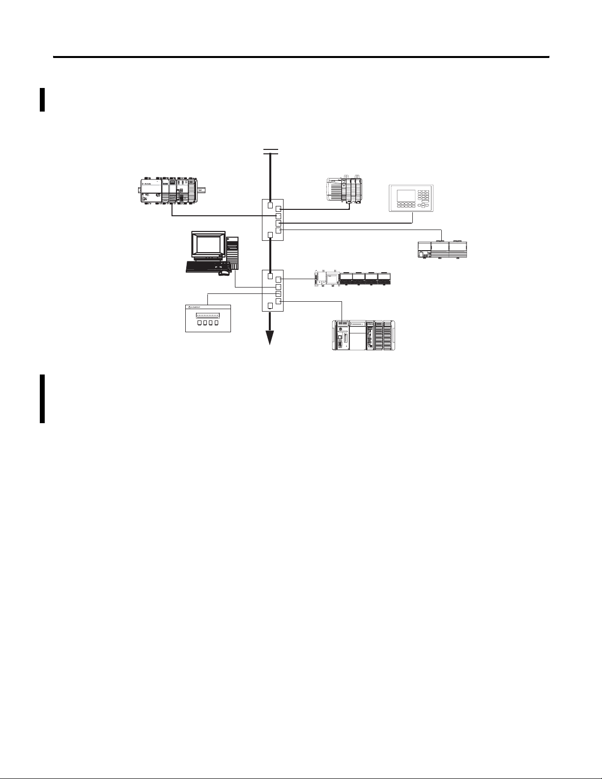
The following diagram shows how EWEB modules might fit in your
control system on an EtherNet/IP network.
1768-L43 CompactLogix
Controller with 1768-EWEB
Module
Power
OUT
L1
L2/N
Computer with RSLogix,
RSLinx, and Web
Browser Software
PowerMonitor 300 With
Ethernet Card
Firewall/Router
ControlLogix Controller
With 1756-EWEB Module
PanelView Terminal
Ethernet Switch
FLEX I/O System with
MicroLogix Controller
1794-AENT Adapter
with 1761-NET-ENI
1769-L35E CompactLogix
Controller
If both the ControlLogix and CompactLogix chassis in this sample
system contain an EWEB module, you could access either module to
monitor and modify data in the controllers using a computer with
standard Web browser software.
Publication ENET-UM527E-EN-P - October 2006
Page 17
Getting Started 17
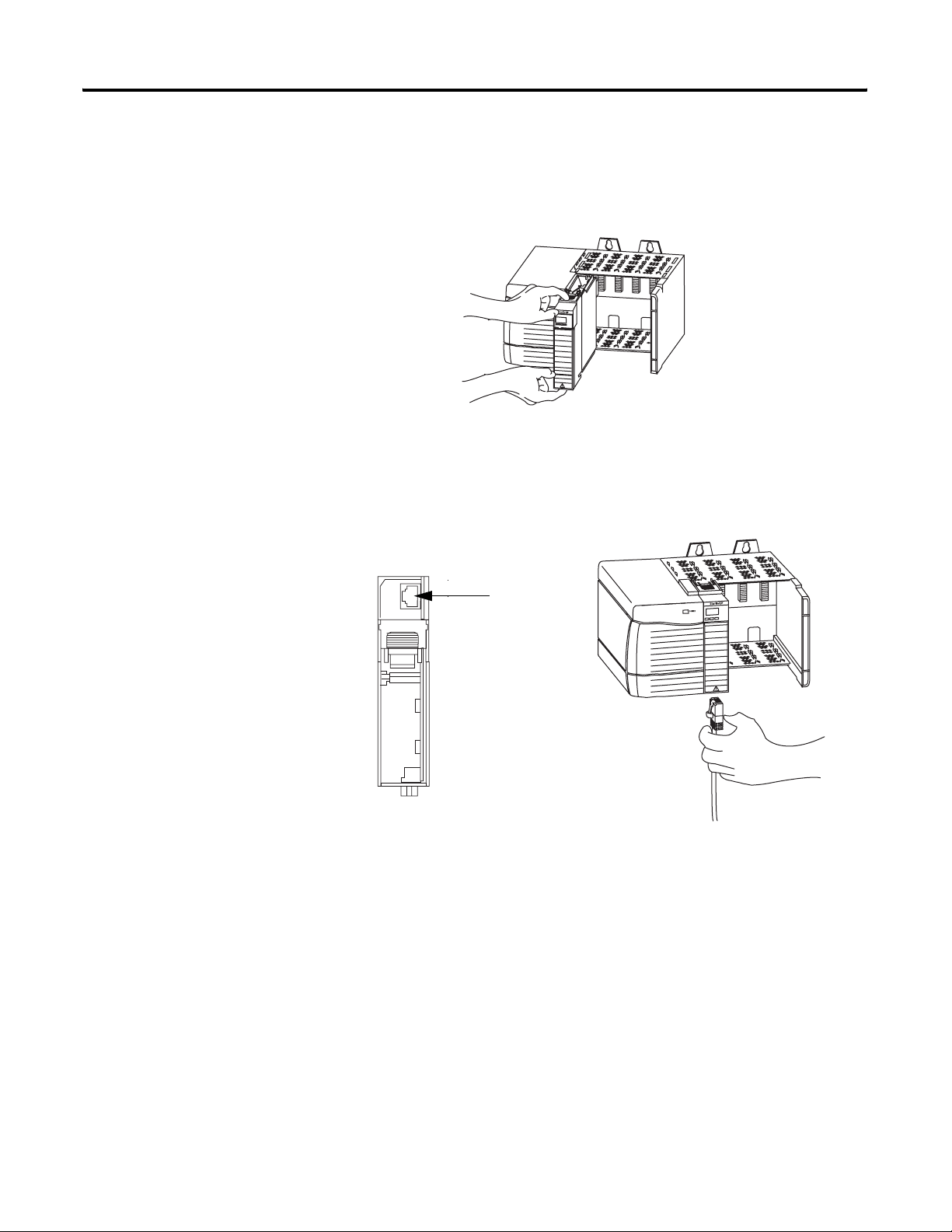
1756-EWEB Installation
To install a ControlLogix Enhanced Web Server Module (1756-EWEB),
follow these steps.
1. Align the module with a slot in the 1756 chassis.
2. Slide the module back into the chassis until it snaps into place.
3. Connect the module to the network.
The RJ-45 connector is on the bottom, front of the module.
1756-EWEB, Bottom
RJ-45 EtherNet/IP
Connector
Connect the cable here.
4. Obtain an IP address.
For more information, see chapter 2.
By default, the web server module is DHCP enabled. If you
connect the web server module to a network that has a DHCP
server, that server will assign a dynamic IP address to the web
server module and the four-digit display on the front of the web
server module will display each of the four numbers of the IP
address.
If your network does not have a DHCP server, use one of the
methods described in chapter 2 to assign an IP address to the
web server module.
Publication ENET-UM527E-EN-P - October 2006
Page 18
18 Getting Started
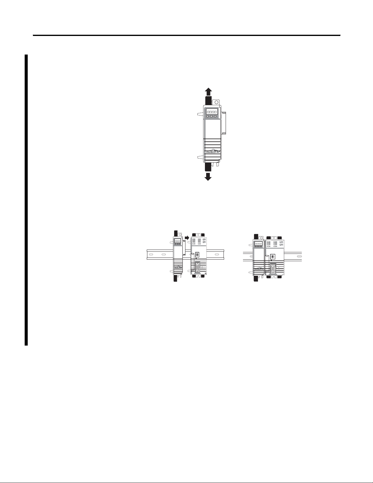
1768-EWEB Installation
To install a CompactLogix Enhanced web Server module, complete
the following steps.
1. Open the DIN rail latches on the module.
2. Align and press the module onto the DIN rail to the left of the
controller.
3. Slide module snugly against the controller.
Publication ENET-UM527E-EN-P - October 2006
4. Install a power supply and other modules.
5. Close all the DIN rail latches.
6. Obtain an IP address.
For more information, see chapter 2.
Page 19
Getting Started 19
System Requirements
Access the Module Using Your Web Browser
Browser Requirements
The following table describes browser requirements for specific tasks
related to the Enhnaced Web Server module.
To You Need
Access web pages generated by the
Enhanced Web Server module
Create and edit data view web pages on the
Enhanced Web Server module
View sample code Internet Explorer 5.5 or 6
Any standard web browser
Internet Explorer 5.5 or 6 with XML support
Display Size
The supported display size is 640 x 480 or greater. Smaller display
sizes work but might require extensive scrolling to view the
information.
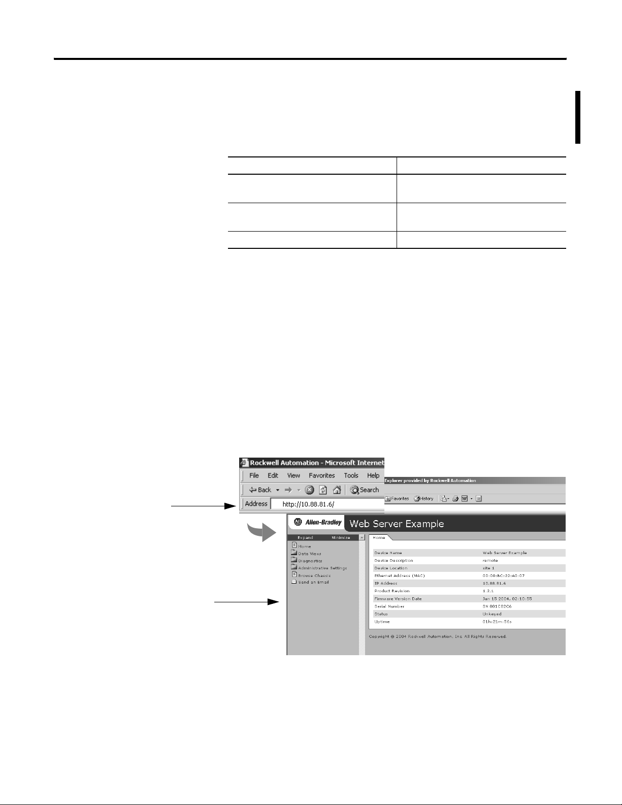
Use the following steps to access your EWEB module using you web
browser.
Specify the IP address of the web
server module in the Address
window of your web browser.
The module’s home page displays.
1. In the address field of your web browser, enter the IP address of
the module to access the module’s home page.
Publication ENET-UM527E-EN-P - October 2006
Page 20
20 Getting Started
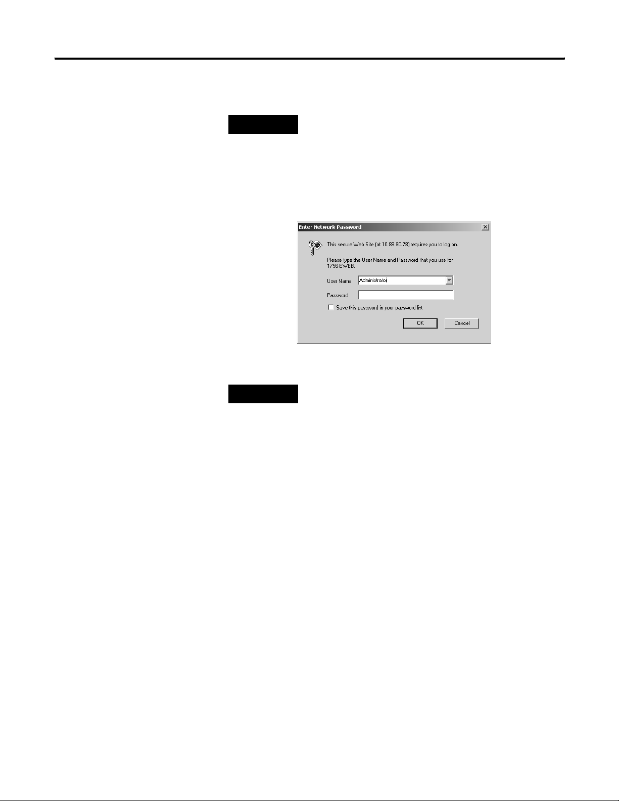
2. Log into the module.
Default Access:
User Name: Administrator
(not case sensitive)
Password:
(leave blank, no password)
TIP
Many of the features of the web server module require you to
log in with appropriate access. If you select a feature such as
New Data View, the web server module prompts you to enter
your user name and password.
3. If logging into the module for the first time, enter the default
user name ’Administrator’ and leave the Password field blank.
4. Click OK.
TIP
You can set up as many as 25 user accounts. Each
account can have read, read and write, or
administrator access.
For more information, see chapter 6.
5. In the organizer on the left, select Administrative Settings >
Device Configuration > Network Configuration.
Publication ENET-UM527E-EN-P - October 2006
Page 21
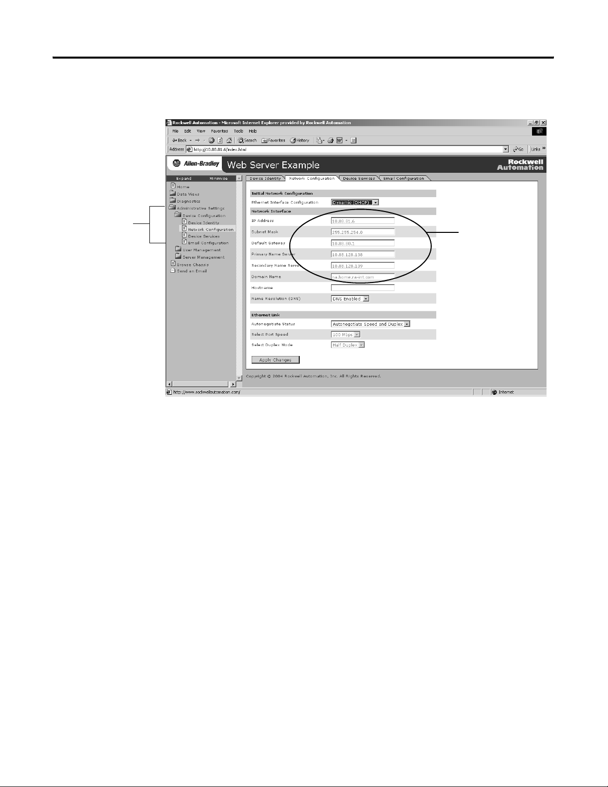
Getting Started 21
6. Confirm the network configuration by verifying the IP address
and other network settings.
Expand Administrative
Settings to Network
Configuration.
Confirm network
settings in these
fields.
For more information, see chapter 2.
Publication ENET-UM527E-EN-P - October 2006
Page 22
22 Getting Started
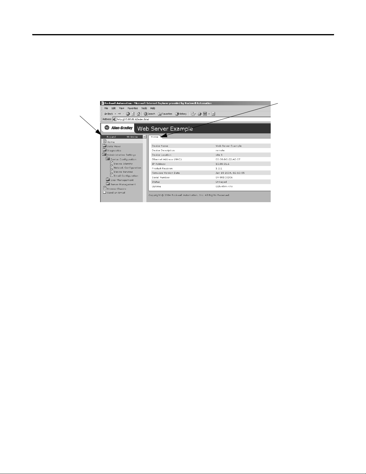
Navigate the Web Server Module
Use the organizer to
navigate folders.
You navigate the web server’s web pages using the organizer on the
left of the screen. You can also use the tabs across the top to navigate
the sections within folders.
Use tabs to navigate
pages within folders.
Publication ENET-UM527E-EN-P - October 2006
Page 23
Getting Started 23
Use the Web Server Module
To help familiarize yourself with the web server module, perform
these basic tasks.
If You Want To See Page
Create a Data View 23
Access a Data View 24
Configure Email 26
Configure the Time Server 27
Enable/disable Other Services 28
Create a Data View
Before you can create a data view in the web server, the tags you
want to view must exist in the local controller (that is, the controller in
the same chassis as the EWEB module) program.
To complete these example, use programming software to create a tag
with the following:
Expand Data View
to New Data View.
– Alias: TEST
Type: DINT
Controller-scope
Value: 12345
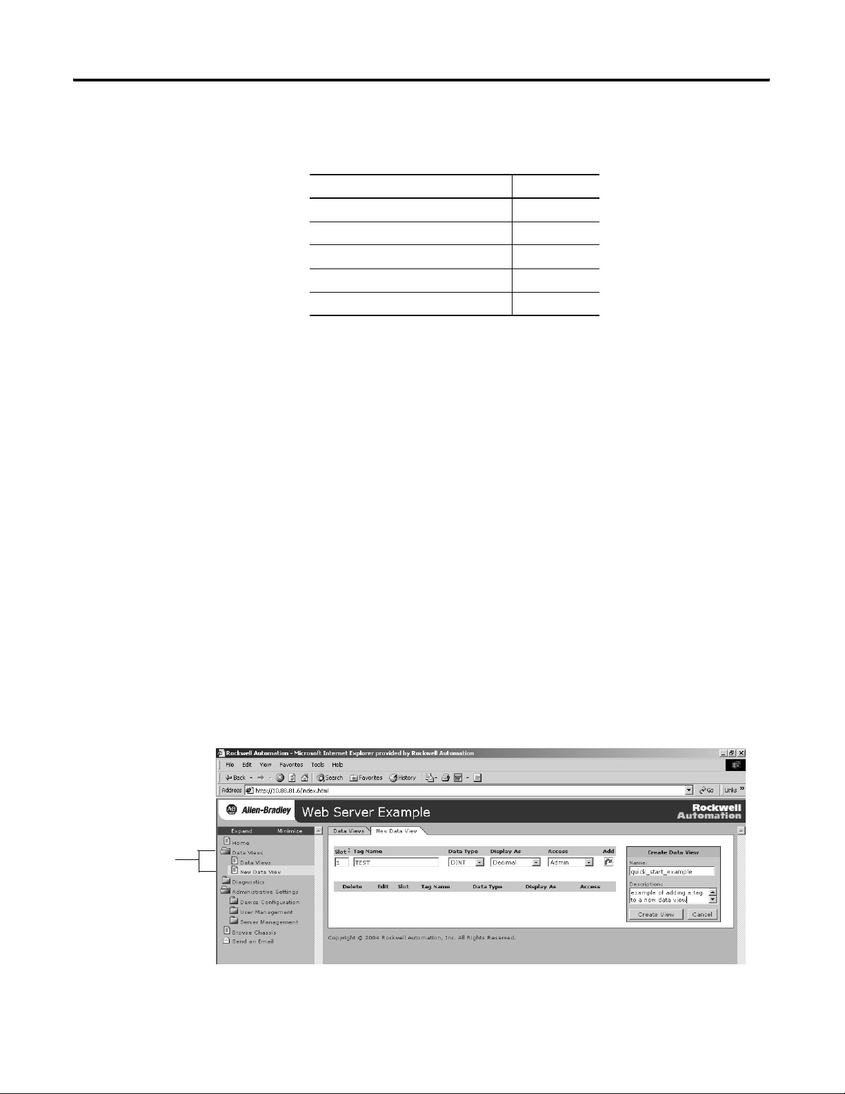
Create a Data View
To create a data view, you need Administrator or Write access.
1. In the organizer on the left, select Data Views > New Data View.
Publication ENET-UM527E-EN-P - October 2006
Page 24
24 Getting Started
2. In the Create Data View box, specify a name for the data view
and enter an optional description.
3. Specify the:
– slot number of the controller.
– tag name (case sensitive; must be exactly as it is specified in
the controller).
– type of tag.
– how to display the tag data.
– access limit of the data view.
4. Click on the Add button to add the tag to the data view.
Continue adding as many tags as you want to configure.
5. Click Create View.
For more information, see chapter 4.
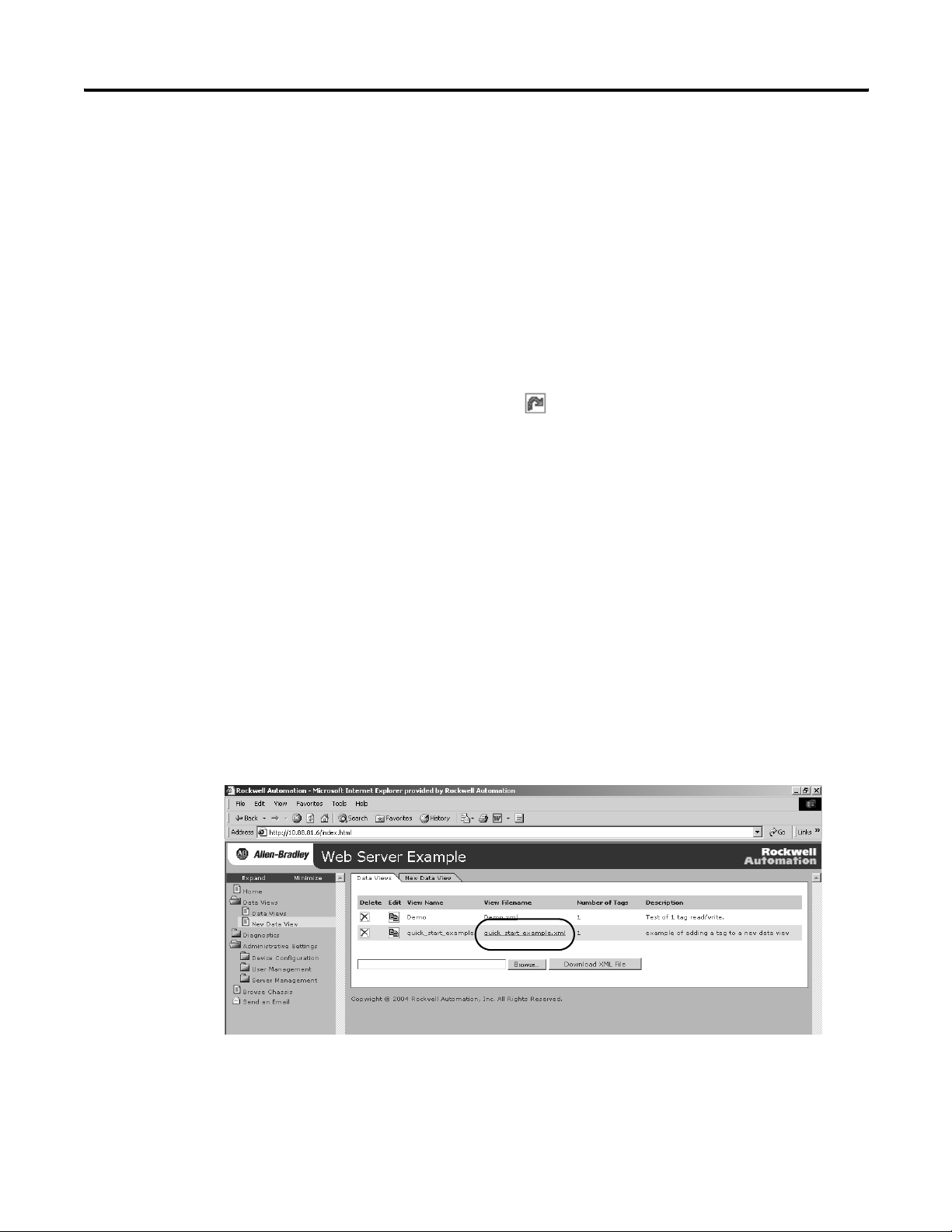
Access a Data View
1. In the organizer on the left, select Data Views > Data View.
-OR-
Click the Data Views tab.
Publication ENET-UM527E-EN-P - October 2006
2. Click on the filename of the Data View you just created.
Page 25
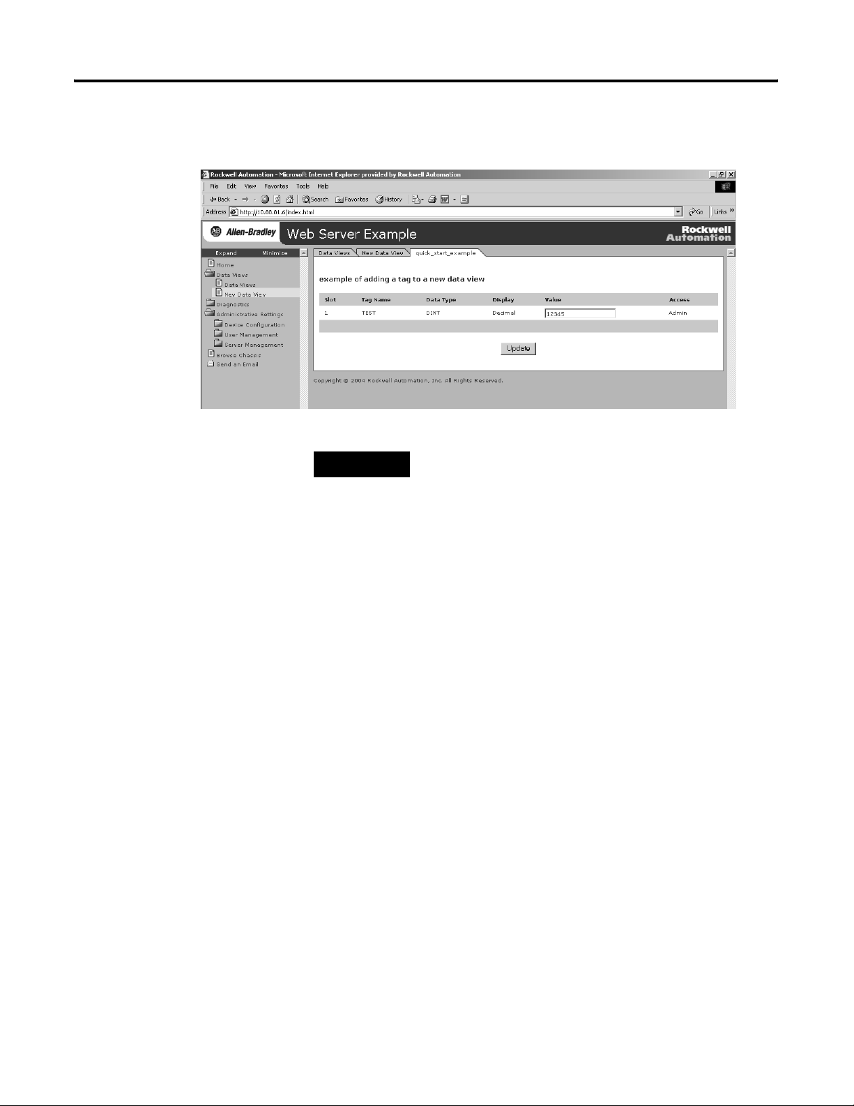
The created tags appear.
Getting Started 25
TIP
To change a data value, you need Administrator or Write
access.
3. If you want to change a tag value, enter the new value in the
Value field the tag and click the Update button.
This changes the value in the controller. You can use
RSLogix5000 software to monitor tags and verify that the value
changed.
For more information, see chapter 4.
Publication ENET-UM527E-EN-P - October 2006
Page 26
26 Getting Started
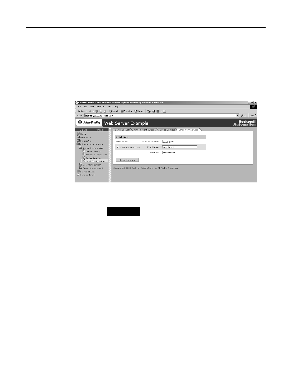
Configure Email
To configure the SMTP server that manages email, follow this
procedure.
1. In the organizer on the left, select Administrative Settings >
Device Configuration > Email Configuration.
2. In the organizer, select Send an Email to create and send email.
TIP
You can have a controller execute a MSG instruction that
initiates email through the web server module.
For more information, see chapter 5.
Publication ENET-UM527E-EN-P - October 2006
Page 27
Getting Started 27
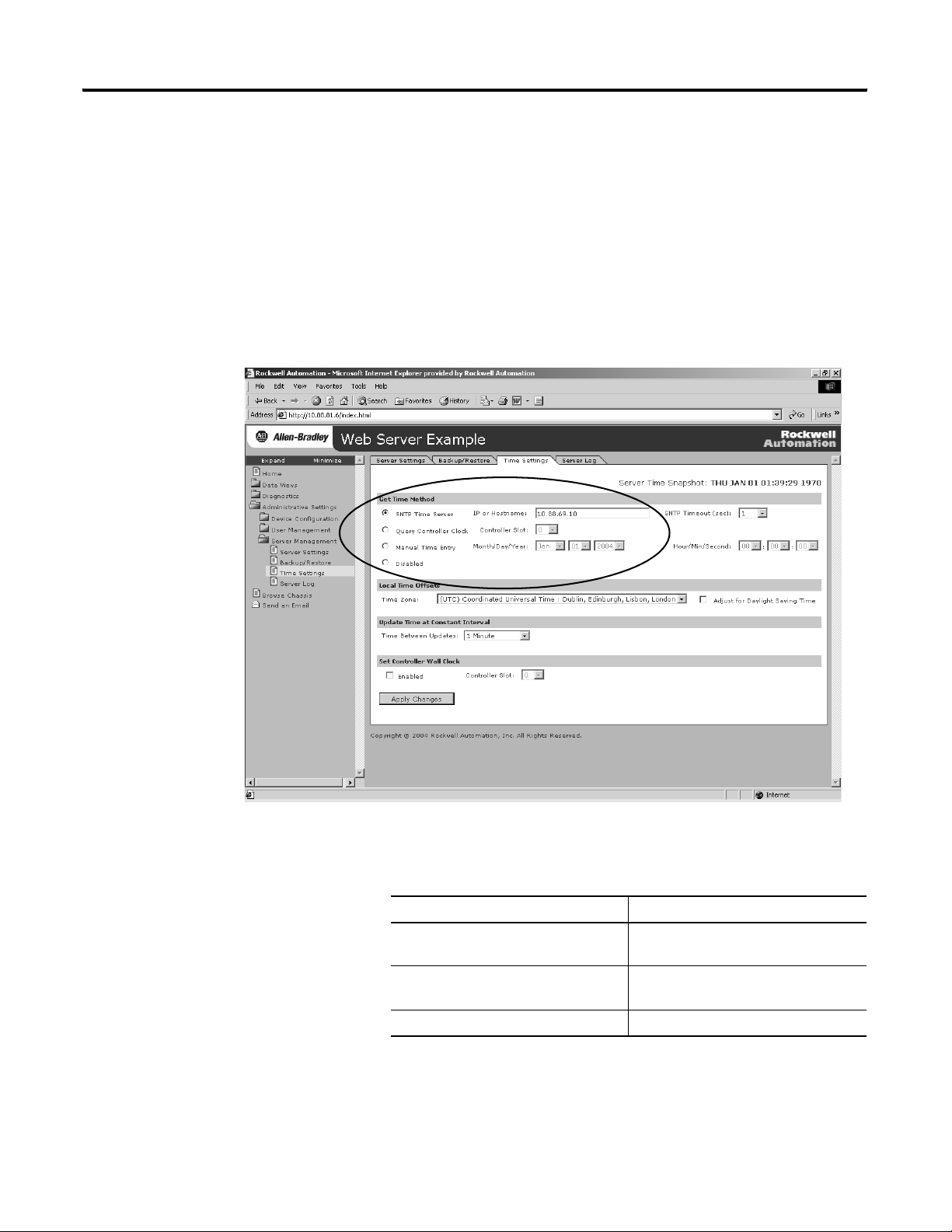
Configure the Time Server
Configuring the Time Server helps ensure that files you save to the
web server module have accurate date and time stamps.
Complete the following steps to configure the time server.
1. In the organizer on the left, select Administrative Settings >
Server Management > Time Settings.
2. Click the radio button to specify the time/date source according
to your system.
To Sel ec t
Get the date and time from an SNTP
server on the network.
Get the time and date from the local
controller
Specify your own date and time Manual Time Entry
SNTP Time Server
Query Controller
For more information, see chapter 3.
Publication ENET-UM527E-EN-P - October 2006
Page 28
28 Getting Started
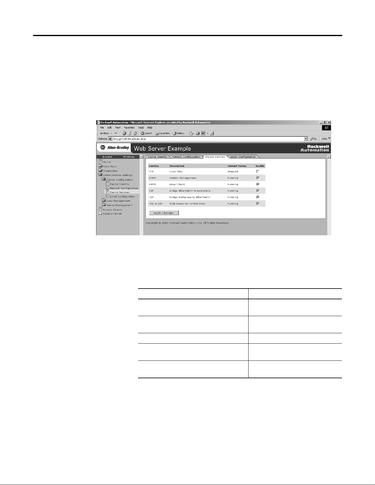
Enable/disable Other Services
Use this procedure to enable other services.
1. In the organizer, select Administrative Settings > Device
Configuration > Device Services.
2. Select the services you want to use by checking the appropriate
checkboxes.
Use the following table as a reference.
To Enable
Allow file tyransfers to and from the web server
module
Use SNMP management software (if your
system has it)
Service email Simple Mail Transfer Protocol (SMTP)
Allow Ethernet/IP devices to bridge through the
web server module to devices in the chassis
Allow web access to control system data Extended Markup Language/Active
File Transfer Protocol (FTP)
Simple Network Mangament Protocol
(SNMP)
Common Industrial Protocol (CIP) bridge
backplane to EtherNet/IP service
Server Page (XML/ASP)
For more information, see chapter 3.
Publication ENET-UM527E-EN-P - October 2006
Page 29
Getting Started 29
Additional Resources
Topic Publication Title Publication No.
Creating controller tags using
RSLogix5000
EtherNet/IP network EtherNet/IP Modules in Logix5000 Control Systems
1756-EWEB module installation EtherNet/IP Web Server Module Installation
1768-EWEB module installation EtherNet/IP Web Server Module Installation
Consult the following publications for more information.
Logix5000 Controllers Common Procedures 1756-PM001
ENET-UM001
User Manual
1756-IN588
Instructions
1768-IN007
Instructions
You can view or download publications at
http://www.literature.rockwellautomation.com
. To order paper copies
of technical documentation, contact your local Rockwell Automation
distributor or sales representative.
Publication ENET-UM527E-EN-P - October 2006
Page 30

30 Getting Started
Publication ENET-UM527E-EN-P - October 2006
Page 31

Chapter
Configure a Network Address For a Web Server Module
2
How to Use This Chapter
Determine Which Network Parameters Are Required
Ethernet Parameter Description
IP Address The IP address uniquely identifies the module. The IP address is in the form
Subnet mask Subnet addressing is an extension of the IP address scheme that lets a site to use a single
This chapter describes how to configure a module to operate on an
Ethernet network.
Topic Page
Determine Which Network Parameters Are Required 31
Assign Network Parameters When the Network Has a DHCP
Server
Assign Network Parameters Without A DHCP Server 35
Duplicate IP Address Detection 40
IP Address Swapping 42
DNS Addressing 42
Verify Network Settings 44
For the module to operate on an Ethernet network, you must define
these parameters.
xxx.xxx.xxx.xxx where each xxx is a number between 0...255. You cannot use these
reserved values:
• 127.0.0.1
• 0.0.0.0
• 255.255.255.255
network ID for multiple physical networks. Routing outside of the site continues by
dividing the IP address into a net ID and a host ID via the class. Inside a site, the subnet
mask is used to redivide the IP address into a custom network ID portion and host ID.
32
Gateway A gateway connects individual physical networks into a system of networks. When a node
needs to communicate with a node on another network, a gateway transfers the data
between the two networks.
31 Publication ENET-UM527E-EN-P - October 2006
Page 32

32 Configure a Network Address For a Web Server Module
If you use the module to initiate MSG instructions that use host names
or to initiate emails, you must also define these parameters.
Ethernet Parameter Description
Host Name A host name is part of a text address that identifies the host for a module. The full text
address of a module is host_name.domain_name.
Domain Name A domain name is part of a text address that identifies the domain in which the module
resides. The full text address of a module is host_name.domain_name. The domain name
has a 48-character limit.
If you specify a DNS server, you must enter a domain name. Also, if you send email from
the module, some mail relay servers require a domain name be provided during the initial
handshake of the SMTP session.
Primary DNS Server Address This identifies the DNS server(s), if used in the network. You must have a DNS server
Secondary DNS Server Address
configured if you specified a domain name or a host name in the module’s configuration.
The DNS server converts the domain name or host name to an IP address that can be used
by the network.
Check with your network administrator to determine if you need to
specify all of the above parameters.
Assign Network Parameters When the Network Has a DHCP Server
How you configure these network parameters depends on whether
the Ethernet network has a DHCP server.
By default, the web server module is DHCP enabled. DHCP (Dynamic
Host Configuration Protocol) software automatically assigns IP
addresses to client stations logging onto a TCP/IP network.
If you connect the web server module to a network that has a DHCP
server, that server will assign an IP address to the web server module
and the four-digit display on the front of the web server module will
display each of the four numbers of the IP address.
In the Address field of your web browser, enter the IP address that
displays on the front of the module.
Publication ENET-UM527E-EN-P - October 2006
Page 33

Specify the IP address of the web
server module in the Address
window of your web browser.
This is the module’s Home page.
Configure a Network Address For a Web Server Module 33
The module home page displays.
The IP address from the DHCP server provides initial access to the
web server module. Check with your network administrator on
whether you need to modify the IP address for future access to the
module. The network administrator might have you:
• convert the initial IP address to a static IP address.
• enter a different, unique IP address and configure that new
address as a static address.
• do nothing because the DHCP server was configured so that the
initial IP address is already permanently assigned to the web
server module.
• assign a static IP address.
Publication ENET-UM527E-EN-P - October 2006
Page 34

34 Configure a Network Address For a Web Server Module
If your network configuration requires a static IP address, configure
the IP address by selecting Administrative Settings > Device
Configuration > Network Configuration.
IMPORTANT
Do not simply configure the initial address assigned by the DHCP
server as a static IP address. Contact your network administrator for
an appropriate static IP address.
1. Access the Network Configuration page.
2. Enter the static IP address
3. Select Static for the Ethernet Interface Configuration
Publication ENET-UM527E-EN-P - October 2006
Page 35

Configure a Network Address For a Web Server Module 35
Assign Network
If a DHCP server is not available, you must assign a static IP address
to the module. Select one of these methods:
Parameters Without A
DHCP Server
If You Are Working in These Conditions Use This Method For Assigning Network
Parameters
In any condition, the Rockwell Automation BOOTP/DHCP
utility is recommended.
The module is connected to other NetLinx networks. RSLinx software 38
The RSLogix 5000 project is online with the controller that
communicates to or through the web server module.
After using one of these utilities, select Administrative Settings >
Device Configuration > Network Configuration to set additional
parameters.
Rockwell BOOTP/DHCP utility
(available with RSLinx and RSLogix 5000 software)
RSLogix 5000 software 39
See Page
36
Publication ENET-UM527E-EN-P - October 2006
Page 36

36 Configure a Network Address For a Web Server Module
Use the Rockwell Automation BOOTP/DHCP Utility
The module ships with DHCP enabled. The BOOTP/DHCP utility is a
stand alone program that lets you interactively define the IP address of
a module that is issuing DHCP or BOOTP requests. The utility is
located in the:
• BOOTP-DHCP Server folder in the Rockwell Software program
• Tools directory on the RSLogix 5000 installation CD.
folder on the Start menu.
The utility is automatically installed when you install
RSLinx software.
IMPORTANT
Before you start the BOOTP/DHCP utility, make sure you have the
hardware (MAC) address of the web server module. The hardware
address is on a sticker located on the side of the module. The
hardware address in a format similar to: 00-0b-db-14-55-35.
To use the BOOTP/DHCP utility:
1. Launch the BOOTP/DHCP software.
In the Request History panel you see the hardware addresses of
modules issuing requests.
Publication ENET-UM527E-EN-P - October 2006
2. Double-click on the hardware (MAC) address of the module you
want to configure.
Page 37

Configure a Network Address For a Web Server Module 37
The hardware address is on a sticker located on the side of the
web server module. The hardware address will be in a format
similar to: 00-0b-db-14-55-35.
The New Entry window displays the MAC address you selected
and prompts you to enter the IP address.
3. Enter the IP address of the module.
You can also enter the host name and a description of the
module.
4. Click OK.
The device is added to the Relation List.
5. To permanently assign this configuration to the module,
highlight the module and click on the Disable BOOTP/DHCP
button.
When power is recycled, the module uses the configuration you
assigned and does not issue a request.
Publication ENET-UM527E-EN-P - October 2006
Page 38

38 Configure a Network Address For a Web Server Module
If you use the BOOTP/DHCP utility in an uplinked subnet where an
enterprise DHCP server exists, the module may get an IP address from
the enterprise server before the BOOTP/DHCP utility even sees the
module. To avoid this, disconnect from the uplink to set the address
and have the module remember its static address before reconnecting
to the uplink. This is not a problem if you have node names
configured in the module and leave DHCP enabled.
Use RSLinx Software to Configure the IP Address
To use RSLinx software to configure the IP address:
1. Make sure the web server module is installed and powered.
If you do not select the Disable BOOTP/DHCP button, on a
power cycle, the web server module clears the current IP
configuration and will again begin sending requests.
2. Start RSLinx software.
3. Click the RSWho icon.
RSWho Icon
4. Expand the network configuration organizer until you reach the
module.
5. Right-click on the module and select Module Configuration.
Publication ENET-UM527E-EN-P - October 2006
Page 39

Configure a Network Address For a Web Server Module 39
6. Select the Port Configuration tab.
7. In the Network Configuration box, click Static to permanently
assign the configuration.
If you select Dynamic on a power cycle, the controller clears the
current IP configuration and will again begin sending requests.
8. Enter the IP address and the other network parameters, if
needed.
Use RSLogix 5000 Software to Configure the IP Address
To use RSLogix 5000 software to configure the IP address:
1. Make sure the module is installed and powered up.
2. Connect to the controller via a serial or other network
connection.
3. Start RSLogix 5000 software.
4. In the Controller Organizer, select the EtherNet/IP module and
right-click.
Publication ENET-UM527E-EN-P - October 2006
Page 40

40 Configure a Network Address For a Web Server Module
5. Select Properties.
Duplicate IP Address Detection
6. Select the Port Configuration tab and specify the IP address and
the other network parameters, if needed.
7. Click Apply.
8. Click OK.
This sets the IP address in the hardware. This IP address should
be the same IP address you assigned under the General tab.
On this screen, you can also specify port speed (10 Mbps or
100 Mbps) and duplex mode (autonegotiate, half duplex, or full
duplex). The module configuration needs to agree with how the
switch is configured. See your network administrator for more
information.
1756-EWEB modules with firmware revision 2.2 or later support
duplicate IP address detection.
All 1768-EWEB module firmware revisions support duplicate IP
address detection.
Publication ENET-UM527E-EN-P - October 2006
For more information about EtherNet/IP modules that support
duplicate IP address detection, see the EtherNet/IP Modules in
Logix5000 Control Systems User Manual, publication
ENET-UM001.
Page 41

Configure a Network Address For a Web Server Module 41
When you change the IP address or connect a web server module to
an EtherNet/IP network, the module checks to make sure that the IP
address assigned to this module is not the same as that for any other
device already on the network.
If the module determines that there is a conflict (some other device on
the network already has the IP address), the EtherNet/IP port of the
module goes into conflict mode, where the module’s:
• OK LED indicator blinks red.
• network (NET) LED indicator is solid red.
• front display indicates the conflict.
The display scrolls: OK <IP_address_of_this_module> Duplicate
IP <Mac_address_of_duplicate_node_detected>
For example: OK 10.88.60.196 Duplicate IP - 00:00:BC:02:34:B4
To correct this conflict, use the instructions in this chapter to change
the IP address of the module. Then cycle power to the module or
reset the module (such as disconnecting the EtherNet/IP cable and
reconnecting the cable).
There is also the possibility that two modules can detect a conflict
simultaneously. If this occurs, remove the module that has the
incorrect IP address or correct its conflict. To get the second module
out of conflict mode, cycle power to the module or disconnect its
EtherNet/IP cable and reconnect the cable.
Publication ENET-UM527E-EN-P - October 2006
Page 42

42 Configure a Network Address For a Web Server Module
Duplicate Detection Scenarios
The behavior of devices that are in conflict over an IP address varies,
depending on whether connections have been established to either of
the modules and whether both modules support duplicate IP address
detection.
If Then
Both modules support duplicate IP address
detection
The module that powers up first and uses
the IP address keeps the IP address. The
other module will detect a conflict, give up
the IP address, and enter conflict mode.
IP Address Swapping
Both modules support duplicate IP address
detection and both modules power up at
roughly the same time
One module supports duplicate IP address
detection and a second module does not
Both modules give up the IP address and
enter conflict mode.
the second module generally keeps its IP
address, regardless of which module
obtains the IP address first. The module that
supports duplicate IP address detection will
detect the conflict and give up the IP
address.
1756-EWEB modules with firmware revision 2.2 or later support IP
address swapping.
During a switchover in ControlLogix redundancy systems, these
modules swap their IP addresses with their partner modules in the
other redundant chassis.
For more information about IP address swapping, see the
ControlLogix Redundancy User Manual, publication 1756-UM523.
DNS Addressing
Publication ENET-UM527E-EN-P - October 2006
To further qualify an address of a module, you can use DNS
addressing to specify a host name for a module, which also includes
specifying a domain name and DNS servers. DNS addressing lets you
set up similar network structures and IP address sequences under
different domains.
DNS addressing is necessary only if you refer to the module by host
name and use the web server module to initiate MSG instructions out
of the web server module to another device.
To use DNS addressing, you must:
1. Assign a host name to the module.
Page 43

Configure a Network Address For a Web Server Module 43
Your network administrator should be able to assign a host
name. Valid host names should be IEC-1131-3 compliant.
2. Configure the module parameters.
In addition to the IP address, subnet mask, and gateway address,
you must also configure a host name for the module, domain
name, and primary/secondary DNS server addresses. In the DNS
server, the host name must match the IP address of the module.
IMPORTANT
Make sure the DNS enable bit is set.
If you configure your module using RSLinx software, version
2.41.00 or later, the enable bit is cleared and DNS addressing
will not work. If you configure your module using the Port
Configuration tab in RSLogix 5000 software, the enable bit is
set, so DNS addressing should work.
3. In RSLogix 5000 software, add the module to the I/O
configuration tree and enter the host name in the General tab of
the module.
If a child module resides in the same domain as its parent
module, just enter the host name. If the child module is in a
different domain that its parent module, you must enter the host
name and the domain name (host.domain)
You can also use DNS addressing in a module profile in the I/O
controller tree or in a message path. If the domain name of the
destination module is different from the source module, use a
fully-qualified DNS name (hostname.domainname). For example, to
send a message from ENBT1.location1.companyA to
ENTB1.location2.companyA, the host names are the same, but the
domains are different.
If you do not enter a fully-qualified DNS name, the module appends
the default domain name to the specified host name.
Publication ENET-UM527E-EN-P - October 2006
Page 44

44 Configure a Network Address For a Web Server Module
Verify Network Settings
Select Administrative Settings > Device Configuration > Network
Configuration. An authenticated user may modify network parameters.
In This Field Specify
Ethernet Interface Configuration The network configuration scheme:
• Dynamic BOOTP
• Dynamic DHCP (default)
• Static
IP Address IP address for the web server module:
If you want to specify a static IP address for the web server module, you must also select
Static for the Ethernet Interface Configuration field towards the bottom of this page.
Subnet Mask Subnet mask for the web server module.
Default Gateway Gateway address for the web server module.
Primary Server Name
Secondary Server Name
Domain Name Domain name for the web server module, if using DNS addressing.
Host Name Host name for the web server module, if using DNS addressing.
Name Resolution (DNS) Whether the web server module uses DNS addressing.
DNS server names, if using DNS addressing.
Publication ENET-UM527E-EN-P - October 2006
Page 45

Configure a Network Address For a Web Server Module 45
In This Field Specify
Autonegotiate Status How to determine port speed and duplex:
• Autonegotiate speed and duplex
• Force speed and duplex
Select Port Speed Port speed (10 Mbps or 100 Mbps), if you selected to force speed and duplex.
Select Duplex Mode Duplex (full or half), if you selected to force speed and duplex.
Additional Resources
Topic Publication Title Publication No.
EtherNet/IP modules and networks. EtherNet/IP Modules in Logix5000 Control Systems
EtherNet/IP modules, IP swapping, and
redundancy systems.
Consult the following publications for more information.
ENET-UM001
User Manual
ControlLogix Redundancy User Manual 1756-UM523
You can view or download publications at
http://www.literature.rockwellautomation.com
. To order paper copies
of technical documentation, contact your local Rockwell Automation
distributor or sales representative.
Publication ENET-UM527E-EN-P - October 2006
Page 46

46 Configure a Network Address For a Web Server Module
Publication ENET-UM527E-EN-P - October 2006
Page 47

Manage Module Settings
Chapter
3
How to Use This Chapter
Manage Module Information
This chapter describes how to configure module settings other than
network parameters for the web server module.
Topic Page
Manage Module Information 47
Manage Server Settings 51
To access and modify module-specific information, select
Administrative Settings > Device Configuration from the organizer on
the left. You can:
• define the module-specific information that displays on the
Home page.
• modify network parameters.
• enable/disable communication services.
These settings are stored in flash memory and persist over power
cycles.
47 Publication ENET-UM527E-EN-P - October 2006
Page 48

48 Manage Module Settings
Define Module-specific Information For the Home Page
Select Administrative Settings > Device Configuration > Device Identity
to set specific text that identifies the module. This information appears
on the home page.
In This Field Specify
Device Name A name for the web server module (32 characters maximum)
The device name you enter appears in the title bar of the web server module’s web pages.
This device name also appears in RSLinx when you browse the network.
Device Location Description of the location of the web server module (64 characters maximum)
Device Description Description of the web server module (64 characters maximum)
Contact Information Contact information, such as name, phone number, or email address
(512 characters maximum)
There are two fields so that you can specify contact information for two individuals.
Publication ENET-UM527E-EN-P - October 2006
Page 49

Manage Module Settings 49
Modify Network Parameters
Select Administrative Settings > Device Configuration > Network
Configuration lets to modify network parameters.
Publication ENET-UM527E-EN-P - October 2006
Page 50

50 Manage Module Settings
Enable and Disable Communication Services
Select Administrative Settings > Device Configuration > Device
Services to specify which communication services are enabled or
disabled on the web server module.
In This Field Select Whether To Enable Or Disable the
FTP FTP (File Transfer Protocol) server
Disable FTP to prevent users from accessing the file system on the web server module.
Important: For security purposes, keep FTP disabled unless you frequently transfer files to
or from the web server module.
SNMP SNMP (Simple Network Management Protocol) agent
Enable SNMP if your system uses SNMP management software.
SMTP SMTP (Simple Mail Transfer Protocol) agent
SMTP manages email capability. Disable SMTP if you do not send emails from the web
server module.
CIP Bridge Ethernet to Backplane CIP (Common Industrial Protocol) bridging
Enable this CIP bridging to allow EtherNet/IP devices to bridge through the web server
module to devices in the chassis.
CIP Bridge Backplane to Ethernet CIP (Common Industrial Protocol) bridging
Enable this CIP bridging to allow other devices in the chassis to bridge through the web
server module to EtherNet/IP devices.
XML/ASP XML/ASP (Extended Markup Language/Active Server Page) support
Enable XML/ASP to allow web access to control system data.
Publication ENET-UM527E-EN-P - October 2006
Page 51

Manage Module Settings 51
Manage Server Settings
Select Administrative Settings > Server Management to customize some
of the server settings of the module, as well as back up the file system
on the web server module. You can:
• customize server settings, including web home page.
• lock access to the module during backup or restore procedures.
See chapter 6 for more information on backing up the web
server module.
• configure the time server.
• display a server log.
Customize Server Settings
Select Administrative Settings > Server Management > Server Settings
to customize the web home page and server settings of the web server
module.
Publication ENET-UM527E-EN-P - October 2006
Page 52

52 Manage Module Settings
In The Field Take This Action
Web Home Page Select which home page is the default, 1756-EWEB Default (index.html) or select and
specify a custom home page address.
For example, a custom web page could be:
/user/Web/mypage.html
mypage is the name of the file for the custom web page.
You must copy a custom home page to the web server module before you can use it. See
chapter 8 for information on creating a custom web page.
Server Port Number Select the default port number (80) for the HTTP port on the web server module or specify
a custom port number.
Server Log Enable or disable the server log.
You view the server log from the Server Log page under the Server Management folder.
See page 54 for how to display the server log.
Log Filters If you enable the Server Log, specify which of the following information you want to be
recorded for the web server log.
Timestamp of HTTP request (access)
URL requested on the web server module
Server HTTP Code
IP Address of the requestor
Access (Administrator, Write, or Read)
Publication ENET-UM527E-EN-P - October 2006
Page 53

Manage Module Settings 53
Configure the Time Server
To configure the Time Server, select Administrative Settings > Server
Management Server > Time Settings. Doing so helps makes sure that
files you save to the web server module have accurate date and time
stamps. You can also enable the local controller to get its time and
date from the web server module.
Select This Field If You Want To
SNTP Time Server Use the time from the Network Time Protocol (NTP).
Specify the IP address or host name of an SNTP server on the network. The web server
uses port 123 for this service. The IP address you enter persists over power cycles.
Query Controller Clock Use the time from the local Logix controller (Wall Clock Time).
Specify the slot number of the controller. The web server module queries the Wall Clock
Time of the controller for both time and date. At subsequent power ups, the web server
module queries the controller.
Manual Time Entry Manually set the time and date.
Manual settings do not persist over power cycles.
Local Time Offsets Select the appropriate time zone.
This selection is only available when you select SNTP time server as your “Get Time
Method.”
Update Time at Constant Interval Select how often the web server module updates its date and time.
Set Controller Date/Time Use the date and time in the web server module to set the date and time in the local
controller.
You must also specify the slot number of the local controller.
Important: This feature provides accurate time synchronization to within one second.
Publication ENET-UM527E-EN-P - October 2006
Page 54

54 Manage Module Settings
Display the Server Log
To display the server log, select Administrative Settings > Server
Management Server > Server Log. This page, when enabled, displays
records of web accesses to the web server module. Only those
information fields that are enabled on the Server Setting page (see
page 51) appear in the server log. The information displayed on this
page is stored in RAM and does not persist over power cycles.
This Field Specifies
Timestamp Timestamp of HTTP request (access).
URL Requested URL on the web server
module.
HTTP code HTTP code request.
IP address IP address of the requestor.
Access Type of access.
The web server module has 30 K memory allocated for server log
entries. If all the log options are enabled, the server log memory can
hold about 200 entries. Once this allocation is full, the web server
module stops storing server log entries. Click Clear Log to empty the
server log so that the web server module can again log entries.
Publication ENET-UM527E-EN-P - October 2006
Page 55

Chapter
4
Use Data Views to Access Controller Data
About This Chapter
The module provides access to controller data for monitoring and
data modification of controller tags.
This chapter shows you how to set up data views of controller tags.
Topic Page
Data Views Overview 55
Create a Data View 57
Monitor Data Views and Tag Data 59
Create Data Views Offline 62
Edit a Data View 62
Use an External Application to Access Data Views 63
Example: Data View XML 64
Example: Data View XML with Tag Values 65
Example: Data View XML with Tag Errors 66
For data views, the module must be in the same chassis as the
controller.
Data Views Overview
55 Publication ENET-UM527E-EN-P - October 2006
Data views give you the ability to read from and write to RSLogix
controller tags from a browser interface or an external application.
The module provides web pages that let you configure a set of tags (a
data view) that can be read or written.
A data view consists of an XML file with data tag information The XML
file is in a readable ASCII format. It contains the tag name, data type,
path, display formatting, and privilege access level. Each tag value is
exposed as a separate element and an error attribute is optional.
Page 56

56 Use Data Views to Access Controller Data
Tags Supported In Data Views
To configure tags in data views:
• You can only access tags in controllers that reside in the local
chassis (same chassis as the web server module).
• Tags must be controller-scoped.
• Tags must be an atomic type (BOOL, SINT, INT, DINT, REAL,
STRING).
You can specify a member of a structure or an array, but you
cannot specify an entire structure or array. BOOL arrays are not
supported.
• A tag can appear only once in a particular data view. You
cannot, for example, have two instances of the same tag with
different display formats.
• There is no limit to the number of data views as long as the total
number of entries in all data views on one web server module
does not exceed 2500 entries.
• Each tag you configure on a data view is one entry. If you
configure the same tag in multiple data views, each tag is
considered one entry.
Performance Estimates
For access to the XML data views, the module can produce data
according to the values listed in this table. This table assumes the
absence of significant CIP traffic and does not take into account the
amount of the time for the browser to render the data view page.
Tags Per Data View Time Per Data View
10 100 ms
100 350 ms
1000 3 sec
Publication ENET-UM527E-EN-P - October 2006
Page 57

Use Data Views to Access Controller Data 57
Create a Data View
Each data view contains a group of tags that you want to monitor.
Each module can support multiple data views.
You create a data view by selecting Data Views > New Data View.
1. Use the Create Data View window on the right of the window to
enter a data view name (required) and description (optional).
2. Add at least one tag to the data view.
Publication ENET-UM527E-EN-P - October 2006
Page 58

58 Use Data Views to Access Controller Data
3. Click the Add button to add the tag you just specified.
You can add multiple tags to the data view, as long as there are
no more than 2500 tags in all the data views of one web server
module.
4. Click the Create View button to create the data view.
Add Tags to a Data View
When you add a tag to a data view, you specify the following
information.
In This Field Specify Details
Slot Slot number of the controller
Tag Name Name of the tag These fields must match exactly what is specified for the tag in the selected
Data Type Data type of the tag
Display As Display type to use for the tag
Access Whether you require Administrator,
Write, or Read access to view the
tags in this data view
Click on the question mark next to Slot
-OR-
Use the Chassis Browse page to validate the controller slot.
controller. To verify tag information, you can use:
• RSLogix 5000 software to view the controller project.
• RSLinx software to navigate to the controller and view tags.
The default access level is Administrator.
The access you specify applies to the whole data view, not just the tag. If you
have multiple tags with different access levels in the same data view, the
web server assigns the highest (most access) level to the data view.
Publication ENET-UM527E-EN-P - October 2006
See chapter 6 for details on access levels.
Page 59

Use Data Views to Access Controller Data 59
Monitor Data Views and Tag Data
Select Data Views > Data Views to view existing data views.
Click on the file name to view the tags within a data view.
The data view displays in an XML format using an XSL style sheet. To
quickly access the XML file, right-click in the data view and in:
• Internet Explorer, select View Source and save the resulting text.
• Netscape or Mozilla, select This Frame > Save As.
You can also use the backup/restore function to FTP a copy of the
XML file. See chapter 7.
If the fields specified for the tag do not match the tag as it is specified
in the controller, this page indicates an error and the tag value shows
xsi:nil for its value.
From this page, you can modify the value of a tag if you have
Administrator or Write access. Enter the new value and click Update.
TIP
To avoid impacting controller execution, data view pages do not
auto-refresh.
Publication ENET-UM527E-EN-P - October 2006
Page 60

60 Use Data Views to Access Controller Data
Click a column heading
to sort the column.
Sort Data Views
You can sort data views alphabetically by name, filename, or
description, or numerically by number of tags.
1. Click a column name.
The first click sorts in ascending order.
2. Click again to sort in descending order.
An arrow next to the column name shows the direction of the
current sort.
You can also sort the tags within a data view by clicking on the
slot, tag name, data type, display as, value, or access headings in
the column title.
Interface with the Logix Controller
When you request to display a data view, the module establishes one
connection to the target controller. Tag values are read and written
over this connection. After the module retrieves the data view or
updates the data view, the module closes the connection.
If someone changes tag names in the target controller and does not
update the tags in the data view, the data view will display an error
message indicating that the tag was not available.
Publication ENET-UM527E-EN-P - October 2006
Page 61

Use Data Views to Access Controller Data 61
Edit a Data View
Follow this procedure to edit an existing data view.
1. Click the edit symbol next to the data view you want to
edit.
At this screen, you can add additional tags or edit existing tags.
2. To edit an existing tag, click the edit symbol next to the tag
name.
3. When you edit a tag, the tag you selected is highlighted and the
tag fields are populated with the previously-configured
information.
4. Change entries in the fields to meet your needs.
Publication ENET-UM527E-EN-P - October 2006
Page 62

62 Use Data Views to Access Controller Data
Create Data Views Offline
You can create data views offline as XML files and later copy them
into the web server module. To create a data view offline:
1. Use a text editor to create an XML data view file.
Right-click in the data view and in:
• Internet Explorer, select View Source and save the resulting
text.
• Netscape or Mozilla, select This Frame > Save As.
You can also use the backup/restore function to FTP a copy of
the XML file. See chapter 7.
2. Scroll to the bottom of the Data Views page on the web server
module.
a. Use the Browse button to locate the XML data view file.
b. Use the Download XML File button to copy the XML data
view file to the module.
Data views are stored in the /user/system/dataviews/ directory
on the web server module.
Publication ENET-UM527E-EN-P - October 2006
Page 63

Use Data Views to Access Controller Data 63
Use an External
Application to Access
The XML format of data views makes the data views files accessible by
user-written programs. Many programming languages, such as Java
and Visual Basic, can process XML files.
Data Views
User programs access data views by making HTTP requests. This is
just like a web browser, except instead of displaying the data view,
the user program processes the XML data. The browser uses an XSL
stylesheet to display the XML files. The XSD schema files validate
data views.
File Format Description
XSL An XML data view specifies an external XSL stylesheet that contains the rules for
transforming this XML information into HTML. A web browser uses the XSL stylesheet to
display the data view.
The XSL file is stored in address/dataview/dataview.xsl where address is the IP address
or host name of the web server module.
XSD The web server module provides an XML schema (dataview.xsd) for validating data views.
This schema also references the CIPDataTypes.xsd schema.
The XSD files are stored in address/schema/dataview.xsd and
address/schema/CIPDataTypes.xsd where address is the IP address or host name of the
web server module.
Read a Data View with an External Application
For an external application to read a data view, the application issues
an HTTP GET command that specifies the location and filename of the
data view.
Data views are located in the /user/system/dataviews directory. The
URL for a data view named myview would be:
http://IP_address/user/system/dataviews/myview.xml
Change Data In a Data View with an External Application
When an external application completes modifying tag data in a data
view, it should post the modified data view, either as a file attachment
(in a multi-part form) or in a single form field named xml, to the URL
of the data view itself.
Publication ENET-UM527E-EN-P - October 2006
Page 64

64 Use Data Views to Access Controller Data
If all the modified tags are successfully written, the web server module
redirects the application to the newly modified data view. If any tag
cannot be written to the controller, the web server module returns an
HTTP error code with a status message indicating the error.
Example: Data View XML
This is an example XML markup for a data view named alltypes. The
data view contains one tag for each of the supported data types. The
tags are in the controller residing in slot 1.
<?xml version="1.0"?>
<?xml-stylesheet href="/dataview/dataview.xsl" type="text/xsl"?>
<view
xmlns="http://www.rockwellautomation.com/technologies/data_access/data_views/1.0/"
xmlns:xsi="http://www.w3.org/2001/XMLSchema-instance"
xsi:schemaLocation="http://www.rockwellautomation.com/technologies/data_access/data_
views/1.0/ /schema/dataview.xsd"
xmlns:cip="http://www.rockwellautomation.com/technologies/data_access/data_types/1.0
/" name="alltypes" description="">
<tag name="test_tag_bool" valueType="cip:dt_BOOL" path="1,1" display="String"
access="write">
<value xsi:nil="true"/>
</tag>
<tag name="test_tag_sint" valueType="cip:dt_SINT" path="1,1" display="Decimal"
access="write">
<value xsi:nil="true"/>
</tag>
<tag name="test_tag_int" valueType="cip:dt_INT" path="1,1" display="Decimal"
access="write">
<value xsi:nil="true"/>
</tag>
<tag name="test_tag_dint" valueType="cip:dt_DINT" path="1,1" display="Decimal"
access="write">
<value xsi:nil="true"/>
</tag>
<tag name="test_tag_real" valueType="cip:dt_REAL" path="1,1" display="Decimal"
access="write">
<value xsi:nil="true"/>
</tag>
<tag name="test_tag_string" valueType="cip:dt_STRINGI" path="1,1"
display="String" access="write">
<value xsi:nil="true"/>
</tag>
</view>
Publication ENET-UM527E-EN-P - October 2006
Page 65

Use Data Views to Access Controller Data 65
Example: Data View XML
This is an example XML markup for a data view named alltypes
loaded with current tag values. The data view contains one tag for
with Tag Values
each of the supported data types. The tags are in the controller
residing in slot 1.
<?xml version="1.0"?>
<?xml-stylesheet href="/dataview/dataview.xsl" type="text/xsl"?>
<view
xmlns="http://www.rockwellautomation.com/technologies/data_access/data_views/1.0/"
xmlns:xsi="http://www.w3.org/2001/XMLSchema-instance"
xsi:schemaLocation="http://www.rockwellautomation.com/technologies/data_access/data_
views/1.0/ /schema/dataview.xsd"
xmlns:cip="http://www.rockwellautomation.com/technologies/data_access/data_types/1.0
/" name="alltypes" description="">
<tag name="test_tag_bool" valueType="cip:dt_BOOL" path="1,1" display="String"
access="write">
<value xsi:type="cip:dt_BOOL">TRUE</value>
</tag>
<tag name="test_tag_sint" valueType="cip:dt_SINT" path="1,1" display="Decimal"
access="write">
<value xsi:type="cip:dt_SINT">123</value>
</tag>
<tag name="test_tag_int" valueType="cip:dt_INT" path="1,1" display="Decimal"
access="write">
<value xsi:type="cip:dt_INT">28416</value>
</tag>
<tag name="test_tag_dint" valueType="cip:dt_DINT" path="1,1" display="Decimal"
access="write">
<value xsi:type="cip:dt_DINT">1459879936</value>
</tag>
<tag name="test_tag_real" valueType="cip:dt_REAL" path="1,1" display="Decimal"
access="write">
<value
xsi:type="cip:dt_REAL">-247882776235710380000000000000000000.000000</value>
</tag>
<tag name="test_tag_string" valueType="cip:dt_STRINGI" path="1,1"
display="String" access="write">
<value xsi:type="cip:dt_STRINGI">aazz</value>
</tag>
</view>
Publication ENET-UM527E-EN-P - October 2006
Page 66

66 Use Data Views to Access Controller Data
Example: Data View XML
This example a data view named alltypes with error messages for tags
that could not be retrieved.
with Tag Errors
<?xml version="1.0"?>
<?xml-stylesheet href="/dataview/dataview.xsl" type="text/xsl"?>
<view
xmlns="http://www.rockwellautomation.com/technologies/data_access/data_views/1.0/"
xmlns:xsi="http://www.w3.org/2001/XMLSchema-instance"
xsi:schemaLocation="http://www.rockwellautomation.com/technologies/data_access/data_
views/1.0/ /schema/dataview.xsd"
xmlns:cip="http://www.rockwellautomation.com/technologies/data_access/data_types/1.0
/" name="alltypes" description="">
<tag name="test_tag_bool" valueType="cip:dt_BOOL" path="1,1" display="String"
access="write" error="Couldn't read tag!">
<value xsi:nil="true"/>
</tag>
<tag name="test_tag_sint" valueType="cip:dt_SINT" path="1,1" display="Decimal"
access="write" error="Couldn't read tag!">
<value xsi:nil="true"/>
</tag>
<tag name="test_tag_int" valueType="cip:dt_INT" path="1,1" display="Decimal"
access="write" error="Couldn't read tag!">
<value xsi:nil="true"/>
</tag>
<tag name="test_tag_dint" valueType="cip:dt_DINT" path="1,1" display="Decimal"
access="write" error="Couldn't read tag!">
<value xsi:nil="true"/>
</tag>
<tag name="test_tag_real" valueType="cip:dt_REAL" path="1,1" display="Decimal"
access="write" error="Couldn't read tag!">
<value xsi:nil="true"/>
</tag>
<tag name="test_tag_string" valueType="cip:dt_STRINGI" path="1,1"
display="String" access="write" error="Couldn't read tag!">
<value xsi:nil="true"/>
</tag>
</view>
Publication ENET-UM527E-EN-P - October 2006
Page 67

Send Email
Chapter
5
About This Chapter
Overview
If You Want To Then
Send an email to specific personnel when a controller application
generates an alarm or reaches a certain condition.
This chapter describes how to send an email message.
Topic Page
Overview 67
Configure the Web Server to Send Email 69
Send an Email Via the Web Page 70
Send an Email with a Controller-initiated Message
Instruction
For email, the web server module can be located locally or remotely
to the controller chassis.
The web server module is an email client that uses a mail relay server
to send email. There are two ways you can use the web server
modules to send email.
Program the controller to send a MSG instruction to the web server
module.
71
Send controller or application status information on a regular basis
to a project manager.
Test the email configuration of the web server module. Use the Send an Email link on the web server’s Home page.
Use the web server email interface to send an email (you must
enter all email information each time you use this interface).
The web server module only sends the content of a MSG instruction
(or the content of the message entered on the email web page) as an
email to a mail relay server. Delivery of the email depends on the mail
server. The web server module does not receive email.
67 Publication ENET-UM527E-EN-P - October 2006
The MSG instruction then instructs the web server module to send
the email text (contained within the MSG instruction) to the mail
relay server.
Multiple controllers can use the same web server module to initiate
email.
Page 68

68 Send Email
1768-L43 CompactLogix Controller
with 1768-EWEB Module
Power
OUT
L1
L2/N
Ethernet Switch
See the following sample system.
Firewall/Router
ControlLogix Controller
With 1756-EWEB Module
Mail Relay Server
Ethernet Switch
FlexLogix Controller
1769-L35E CompactLogix
Controller
This Device Can
ControlLogix controller Send a MSG instruction to the 1756-EWEB web server module to initiate sending an email
FlexLogix controller
1768 or 1769 CompactLogix controller
to the mail relay server.
Use the path of the MSG instruction to identify the web server module as the target of the
MSG instruction.
1756-EWEB or 1768-EWEB module Send an email to the mail relay server from the email interface on the Send an Email link.
Each time you use this interface, you must enter all email information.
Mail relay server Send email to specified recipients.
The mail relay server determines the delivery of any email send through a web server
module, whether via a MSG instruction or from its built-in interface.
Publication ENET-UM527E-EN-P - October 2006
Page 69

Send Email 69
Configure the Web Server to Send Email
The web server module uses the standard SMTP protocol to forward
an email to a mail relay server. You must configure the web server
module to recognize the appropriate mail relay server.
Some mail servers require a domain name be provided during the
initial handshake of the SMTP session. For these mail servers, make
sure you specify a domain name when you configure the network
settings for the module.
You configure the SMTP server and domain name by selecting
Administrative Settings > Device Configuration > Email Configuration.
Enter the address of the SMTP server that manages email. You can
also select whether the web server module should authenticate to the
SMTP server. The web server module supports only LOGIN
authentication. Check with your network administrator for more
information.
Publication ENET-UM527E-EN-P - October 2006
Page 70

70 Send Email
Send an Email Via the Web Page
Use the Send an Email link to enter and send email text. This method
is a one-time approach to sending an email because you have to enter
all the email information each time you use the link. This link is most
useful for testing the email configuration you specified on the
Administrative Settings > Device Configuration > Email Configuration.
In This Field Enter the
To Email address of the recipient.
From Email address of the sender.
This address is where you want any replies to this email to go. It is
not an email address of the web server module. The web server
module only sends email and does not receive email.
Subject Subject line of the email.
Text window The email text.
Click Send after you specify the email address and enter the text.
Publication ENET-UM527E-EN-P - October 2006
Page 71

Send Email 71
Send an Email with a Controller-initiated Message Instruction
A Logix controller can send a generic CIP message instruction to the
web server module that instructs the web server module to send an
email message to a SMTP mail server using the standard SMTP
protocol. This is useful to automatically communicate controller data
and/or application conditions to appropriate personnel.
IMPORTANT
Be careful to write the ladder logic to ensure the MSG
instructions are not continuously triggered to send email
messages.
Create String Tags
You need two controller-scoped string tags, one to contain the email
text and the other to contain the status of the email transmission.
These tags can contain as many as 474 characters.
You must create a user-defined STRING data type (the default STRING
data type in RSLogix 5000 software is not large enough for most email
text). For example, create a STRING data type named EmailString.
Publication ENET-UM527E-EN-P - October 2006
Page 72

72 Send Email
Tag For Status
Tag For Email Text
Click in the Value box to display this button.
Then click this button to display the String
Browser so you can enter the email text.
Create one controller-scoped tag of this new data type to contain the
email text. Create a controller-scoped second tag of this new data type
to contain the transmission status. For example, create tag
EWEB_EMAIL (to contain the email text) and EmailDstStr (to contain
the transmission status). Both of these tags are of type EmailString.
The text of the email does not have to be static. You can program a
controller project to collect specific data to be sent in an email.
For more information on using ladder logic to manipulate string data,
see the Logix5000 Controllers Common Procedures Programming
Manual, publication 1756-PM001.
Enter the Ladder Logic
Add the MSG instruction that triggers the email. Execute this email
MSG instruction as often as needed.
Publication ENET-UM527E-EN-P - October 2006
Page 73

Send Email 73
Configure the MSG Instruction
Use the following process configure the MSG instruction that contains
the email text.
Click to view the Message
Configuration dialog.
On the Configuration tab of the MSG instruction, configure the MSG
parameters for sending an email.
The Source Length is the number of characters in the
email tag plus 4 characters.
In this example, the email text contains 65 characters.
Publication ENET-UM527E-EN-P - October 2006
Page 74

74 Send Email
In This Field Enter
Service Type Custom
Service Code 4b
Instance 1
Class 32f
Attribute 0
Source Element The tag that contains the email text
Source Length The number of characters in the email text plus 4
Destination A tag to contain the status of the email transmission
where:
This tag is of the STRING data type you created to contain the email text. In this example,
enter EWEB_EMAIL which is of type EmailString
In this example, enter 69 (65 characters in the email + 4)
This tag is also of the STRING data type you created to contain the email text. In this
example, enter EmailDstStr which is of type EmailString
On the Communication tab of the MSG instruction, configure the path
from the controller to the web server module.
The path starts with the controller initiating the MSG instruction
module. Then enter the port the message exits and the address of the
next module in the path. For example, if the web server module is in
the same chassis as the controller and is in slot 2, the path is: 1, 2.
Publication ENET-UM527E-EN-P - October 2006
If all the devices in the path are configured in the initiating controller’s
I/O Configuration tree, you can use the Browse button to select the
Page 75

Send Email 75
target web server module and the software automatically fills in the
path.
For more information on configuring the path of a MSG instruction,
see the Logix5000 Controllers General Instructions Reference Manual,
publication 1756-RM003.
Enter the Text of the Email
Use the string browser to enter the text of the email. In the example
above, you enter the email text into the EWEB_EMAIL tag. To include
“To:”, “From:”, and “Subject:” fields in the email, use <CR><LF>
symbols to separate each of these fields. The “To:” and “From”” fields
are required; the “Subject:” field is optional. Use a second set of
<CR><LF> symbols after the last one of these fields you enter. For
example:
To: email address of recipient $r$l
From: email address of sender$r$l
Subject: subject of message $r$l$r$l
body of email message
The maximum length of an email message is 474 characters. An
additional 4-byte string-length value is added to the tag. As a result,
the maximum source length is 478 characters.
Possible Email Status Codes
Examine the destination element of the email MSG to see whether the
email was successfully delivered to the mail relay server. This
indicates that the mail relay server placed the email message in a
queue for delivery. It does not mean the intended recipient
successfully received the email message.
Here are possible codes that could be in this destination element.
Error Code (Hex) Extended-error
Code (Hex)
0x00 None Delivery successful to the mail relay server.
0x02 None Resource unavailable. The email object was unable to obtain memory resources to
0x08 None Unsupported Service Request. Make sure the service code is 0x4B and the Class is
Description
initiate the SMTP session.
0x32F.
Publication ENET-UM527E-EN-P - October 2006
Page 76

76 Send Email
Error Code (Hex) Extended-error
Description
Code (Hex)
0x11 None Reply data too large. The Destination string must reserve space for the SMTP server
reply message. The maximum reply can be 470 bytes.
0x13 None Configuration data size too short. The Source Length is less than the Source Element
string size plus the 4-byte length. The Source Length must equal the Source Element
string size + 4.
0x15 None Configuration data size too large. The Source Length is greater than the Source Element
string size plus the 4-byte length. The Source Length must equal the Source Element
string size + 4.
0x19 None Data write failure. An error occurred when attempting to write the SMTP server address
(attribute 4) to non-volatile memory.
0xFF 0x0100 Error returned by email server; check the Destination string for reason. The email
message was not queued for delivery.
0x0101 SMTP mail server not configured. Attribute 5 was not set with a SMTP server address.
0x0102 “To:” address not specified. Attribute 1 was not set with a “To:” address AND there is
not a “To:” field header in the email body.
0x0103 “From:” address not specified. Attribute 2 was not set with a “From:” address AND
there is not a “From:” field header in the email body.
0x0104 Unable to connect to SMTP mail server set in Attribute 5. If the mail server address is a
hostname, make sure that the device supports DNS, and that a Name Server is
configured. If the hostname is not fully qualified, i.e., “mailhost” and not
“mailhost.xx.yy.com” then the domain must be configured as “xx.yy.com”. Try “ping
<mail server address>” to insure the mail server is reachable from your network. Also
try “telnet <mail server address> 25” which attempts to initiate a SMTP session with
the mail server via telnet over port 25. (If you connect then enter “QUIT”).
0x0105 Communication error with SMTP mail server. An error occurred after the initial
connection with the SMTP mail server.
0x0106 SMTP mail server host name DNS query did not complete. A previous send service
Publication ENET-UM527E-EN-P - October 2006
See the ASCII text following the error code for more details as to the type of error.
request with a host name as the SMTP mail server address did not yet complete. Note
that a timeout for a DNS lookup with an invalid host name can take up to 3 minutes.
Long timeouts can also occur if a domain name or name server is not configured
correctly.
Page 77

Chapter
6
Manage User Accounts and Access Levels
About This Chapter
This chapter describes how to configure levels of user access to
different information on the module.
Topic Page
User Accounts and Privilege Classes 77
Configure Access Limits For Web Pages 78
Create User Accounts 80
Recover with Unknown Password 81
By assigning user accounts with different access levels, you can
manage which users have access to change network configuration or
have access to view and change data views.
Several pages on the web server module, such as module
configuration pages and data views pages, have default access
protection. Before accessing these pages, you must authenticate your
access by entering a user name and password. The module displays
the log-in box when you access these web pages.
IMPORTANT
Once authenticated, you do not have to re-enter a user name or
password when accessing subsequent pages. You must close
your browser to log out.
The default user name is Administrator with no password.
IMPORTANT
User Accounts and Privilege Classes
77 Publication ENET-UM527E-EN-P - October 2006
The web server module supports multiple user accounts, each with a
user name and password. Each user account is configured for one of
these access levels:
• Administrator (all access)
• Write (read and write access)
• Read (read access only)
The access level determines which web pages each user can access.
You configure access limits for individual web pages.
It is strongly recommended that you set a password for the
default Administrator account.
Page 78

78 Manage User Accounts and Access Levels
Configure Access Limits For Web Pages
You protect individual web pages and data views on a per URL basis.
Each page in the web server module has one of these protection
levels:
• Administrator
• Write
• Read
The protection levels are hierarchical. Administrator users can access
Write and Read protected pages, and Write users can access Read
protected pages.
These predefined pages (those web pages that come with the web
server module) in the web server module have these default access
levels. You can change these access levels, if needed.
Web Page Required Protection Level
Home page No protection
Diagnostics pages
Chassis Browse page
Data Views with read-only tags Read protection
Data Views with write tags Write protection
Data Views with administrator tags Administrator protection
Device configuration pages
Server Management page
User Management page
Send Email page
In Data Views, the access limits you specify for a tag applies to the
whole data view, not just the tag. If you have multiple tags with
different access levels in the same data view, the web server assigns
the highest (most access) level to the data view. For more information,
see chapter 3.
If you develop custom web pages, you must explicitly specify the
access limits for the page if you want access protection. Otherwise,
the custom web page will have no access limits.
You need Administrator access to modify access limits for web pages.
You specify the access limit for a web page by selecting
Administrative Settings > User Management > Edit Access Limits.
Publication ENET-UM527E-EN-P - October 2006
Page 79

Manage User Accounts and Access Levels 79
You can change the default access limits for the predefined web pages
or you can add pages to the protection list, such as custom web
pages. The Edit Access Limits page shows the current list of pages the
user has selected for protection. The predefined pages, though they
have default protection, do not show up in the list.
In This Field Do This
URL Enter the URL for the web page (80 characters maximum, including slashes).
Enter only the relative path of where the page is stored on the web server module, such as
’/user/Web/mypage.html’
Group Select Administrator, Write, or Read access limit for the specified URL
You can configure protection limits for predefined pages, as well as
for user-supplied pages. You can also apply protection to directories
so that all the files in a specified directory have the same access limit.
To specify a directory, enter the URL with a front slash (/) on the end.
If you do not enter the front slash, the protection limit you select is
assigned to the web page. To specify an access limit for the entire
web site, enter only a front slash (/).
Publication ENET-UM527E-EN-P - October 2006
Page 80

80 Manage User Accounts and Access Levels
To see the protection limits for predefined web pages and directories,
unclick the Hide System Access Limits selection. This also provides
access to change the predefined protection limits. You can then use
the Restore System Access Limits selection to return to the default
protection limits.
Create User Accounts
You need Administrator access to create and modify user accounts.
You can create as many as 25 individual accounts. You manage
accounts by selecting Administrative Settings > User Management >
Edit Users.
Publication ENET-UM527E-EN-P - October 2006
Page 81

Manage User Accounts and Access Levels 81
Field Action
User ID Enter the user name for the account (80 characters maximum).
Can contain these characters: A-Z, a-z, 0-9, underscore (_), and dash (-).
Group Select Administrator, Write, or Read access for the user account.
Password Enter the password for the account (80 characters maximum).
Confirm Password Re-enter the same password for the account.
IMPORTANT
Recover with Unknown Password
If you use Internet Explorer, the number of characters allowed for a user ID or
password depends on how many characters “fit in the box.” Larger characters
(such as “W”) take more room and reduce the total number of allowed
characters.
This limitation does not apply if you use Netscape, Mozilla, or some other
browser.
There are no back-door accounts or passwords in the event that you
forget the web server module’s passwords or inadvertently delete all
the Administrator accounts.
To recover a web server module with unknown passwords, you must
use ControlFlash to restore the web server’s flash file system to the
factory default. This operation deletes all user accounts, data views,
and user-loaded web pages. Contact technical support for the
appropriate recovery script and binary file.
Publication ENET-UM527E-EN-P - October 2006
Page 82

82 Manage User Accounts and Access Levels
Publication ENET-UM527E-EN-P - October 2006
Page 83

Chapter
Access Files in the Web Server Module
7
About This Chapter
Access the Web Server’s File System
This chapter describes how to use FTP to access the file system on the
web server module.
Topic Page
Access the Web Server’s File System 83
Back Up the File System On the Web Server Module 87
You use FTP access to store custom web pages and applications on
the web server module.
The web server module has a flash file system that stores web pages
and data views. The following table contains the amount of space
available in each EWEB module’s flash file system.
Catalog No. Mbytes Available
1756-EWEB 5
1768-EWEB 2
Some predefined directories exist to store specific types of data.
Use This Directory For
/user This is the highest directory level you can access on the web server module. It contains
two subdirectories:
• /Web for you to store your custom-created pages or other files
• /system to store configuration files and data views
You can only access this directory (via FTP) when the web server module is in
backup/restore mode.
/user/Web Use this directory to store your custom-created pages or own files. Standard FTP provides
access to this directory; the module does not need to be in any special mode.
/user/system This predefined directory contains two predefined directories:
• /configuration to store network and module configuration files
• /dataviews to store data view files
You can only access this directory (via FTP) when the web server module is in
backup/restore mode.
/user/system/configuration This predefined directory contains network and module configuration files in an XML
format. You can only access this directory (via FTP) when the web server module is in
backup/restore mode.
83 Publication ENET-UM527E-EN-P - October 2006
Page 84

84 Access Files in the Web Server Module
Use This Directory For
/user/system/dataviews This predefined directory contains data view files in an XML format. You can only access
this directory (via FTP) when the web server module is in backup/restore mode.
/schema This directory contains dataview.xsd and CIPDataTypes.xsd schema files for validating
data views. You can only access these .xsd files with a web browser:
• http://ip_address/schema/dataview.xsd
• http://ip_address/schema/CIPDataTypes.xsd
/dataview This predefined directory contains dataview.xsl which is the external XSL stylesheet for
data views. You can only access .xsl file http://ip_address/dataview/dataview.xsl with a
web browser.
There are no restrictions on the type of files you can copy to the web
server module. You are restricted only by the amount of memory
available.
You access this file system using any standard FTP client. By default,
FTP is disabled for the web server module. You enable FTP by
selecting Administrative Settings > Device Configuration > Device
Services.
IMPORTANT
IMPORTANT
Connect to the Web Server Module
FTP access must be enabled for the web server module before you can use FTP to
access the module. You enable FTP on the Administrative Settings > Device
Configuration > Device Services page.
To establish a FTP connection to the web server module, you need
Administrator access to the module. You will also need to enter your
user name and password.
The password is transmitted over the network in plain text. We recommend that
you create a temporary Administrator account for use when you use FTP to
access to the web server module.
Leave FTP disabled except for when actively copying files to or from the web
server module.
Publication ENET-UM527E-EN-P - October 2006
Page 85

Specify the IP address of the web
server module.
This is the /user/Web directory.
Access Files in the Web Server Module 85
To connect to the web server module via FTP, specify the IP address
of the module.
Once connected to the web server module, you have access to the
/user/Web directory. You can create subdirectories, but you cannot
access any directories higher than this user directory (which contain
predefined web pages and files).
The web server module supports four FTP sessions (four different
users with simultaneous FTP access to the module). If you use
Internet Explorer to FTP to the web server module, there are only two
FTP sessions available.
When the web server module is in backup/restore mode, an FTP
session points to a different directory than when the web server
module is not in backup/restore mode. If you have a standard FTP
session open to the web server module, close this before placing the
module in backup/restore mode. Once in backup/restore mode, the
previously open FTP session will no longer point to the correct
directory and files.
File Names and Types
File names can have no more than 80 characters. In addition, the
complete path for any file in the file system can have no more than 80
characters. For example, the user-created web pages go in the
/user/Web folder, which is actually in the file system as
“/root/user/Web” (already 14 characters). Any path underneath this
must have 65 or less characters, including slashes, dots, and
extensions.
File names are case-insensitive and can contain any characters,
including spaces, except for the following characters: ? “ / \ < > * | :
Publication ENET-UM527E-EN-P - October 2006
Page 86

86 Access Files in the Web Server Module
When user files are accessed via HTTP, certain file extensions result in
specific values returned in the Content-Type field.
Here are some Content-Types for the more commonly-used files.
File Extension Content-Type
.htm text/html
.html text/html
.asp text/html
.gif image/gif
.jpg image/jpeg
.css text/cascading style sheet
.txt text/plain
.js application/x-javascript
.exe application/binary
.z application/compressed
.gz application/gzip
.bin application/octet-stream
.oda application/oda
.pdf application/pdf
.ai application/postscript
.eps application/postscript
.ps application/postscript
.xml text/xml
.xsl text/xml
In addition, files with an .asp extension are processed by the web
server as Active Server Pages.
For more information on creating custom web pages, see chapter 8.
Publication ENET-UM527E-EN-P - October 2006
Page 87

Access Files in the Web Server Module 87
Back Up the File System On the Web Server Module
There are several items stored on the web server module that you
might want to archive in a backup copy:
• User accounts and passwords.
• List of URLs selected for read, write, or administrator protection.
• Data views.
• Custom web pages.
• Module configuration data.
To back up these files, you use standard FTP to access the web server
module and then copy or restore files. Using FTP lets you copy files to
or from the web server module without interrupting operation of the
module. FTP also lets your standard FTP-capable clients, such as
Internet Explorer or WinZip to copy the system files.
FTP access during a backup/restore procedure differs from normal
FTP access in that you get access to the /user directory, which
contains the /Web directory that is accessible during normal FTP
access. This lets you back up predefined web pages and data views,
as well as any custom files you have copied to the web server
module.
The Administrative Settings > Server Management > Backup/Restore
lets you lock access to the module while you back up or restore files.
Locking the site prevents other users from HTTP access to the web
server module. Locking the site does not affect bridge functionality
through the web server module, however, restoring files to the web
server module that modify network or module configuration settings
(such as IP address) can affect bridge functionality.
Publication ENET-UM527E-EN-P - October 2006
Page 88

88 Access Files in the Web Server Module
Back Up Files
You must have Administrator access to back up files. To back up files
that reside on the web server module:
1. Select Administrative Settings > Server Management >
Backup/Restore and click Lock Site to lock access to the web
server module.
You must lock access to the web server module to gain FTP
access to the /user directory. The web server module asks to
confirm that you want to lock the site.
This automatically enables FTP access to the web server module.
2. Click the link to the web server module. This appears on the
locked backup/restore page.
Publication ENET-UM527E-EN-P - October 2006
Page 89

This is the /user directory.
Access Files in the Web Server Module 89
The module will require that you enter a valid user name and
password that allows administrator access. Once authenticated, you
have access to the /user directory. This is one directory higher than
the /user/Web directory available during normal FTP operations.
3. Select the files you want to back up.
4. Copy the selected files to a directory on your computer.
5. Unlock access to the module by selecting Administrative Settings
> User Management > Backup/Restore.
Restore Files
You must have Administrator access to restore files. To restore files
from your computer to a web server module:
1. Select Administrative Settings > Server Management >
Backup/Restore and click Lock Site to lock access to the web
server module.
You must lock access to the web server module to gain FTP
access to the /user directory. The web server module asks to
confirm that you want to lock the site.
This automatically enables FTP access to the web server module.
2. Click the link to the web server module.
Publication ENET-UM527E-EN-P - October 2006
Page 90

90 Access Files in the Web Server Module
This appears on the locked backup/restore page.
This is the /user directory.
The module will require that you enter a valid user name and
password that allows administrator access. Once authenticated, you
have access to the /user directory. This is one directory higher than
the /user/Web directory available during normal FTP operations.
3. Select the files from your computer that you want to restore to
the web server module.
4. Copy the selected files to a directory on the web server module.
Publication ENET-UM527E-EN-P - October 2006
5. Unlock access to the module by selecting Administrative Settings
> User Management > Backup/Restore.
Page 91

Create Custom Web Pages
Chapter
8
About This Chapter
IMPORTANT
This chapter describes how to use ASP functions in custom web pages
and how to load custom web pages into the web server module.
Topic Page
Overview 91
Develop a Custom Web Page 93
ASP Function Calls 93
Javascript Libraries 98
Web Page Forms and POST Handlers 102
The web server module provides access to tags within a local controller via a
web browser. However, the web server module is not recommended for use as a
real-time HMI or operator interface.
The predefined web pages that come with the module provide one
method of accessing these tags. The ability to load and run custom
web pages gives you the flexibility to design web pages that better fit
your application. For example, you can define a web page with
standard web content, such as a company logo, contact information,
and links to other web pages. Add the ASP functions to display live
controller data.
Overview
91 Publication ENET-UM527E-EN-P - October 2006
Use your own editor or application to develop the appropriate HTML
and ASP files for your custom web pages. Once these files are ready,
you copy the files to the web server module and configure the pages
as needed.
The following steps outline the process of developing custom web
pages and getting them ready to use.
1. Develop the appropriate HTML and ASP files.
See Develop a Custom Web Page on page 93 for information
about the available ASP functions and other features for
displaying and changing controller data.
2. Use FTP to copy the custom pages to the web server module.
Page 92

92 Create Custom Web Pages
3. Copy your files into the /user/Web directory.
See chapter 7 for more information.
4. Decide whether to make your custom page the default Home
page for the web server module.
TIP
Select Administrative Settings > Server Management Server >
Server Settings. When you click the Custom button, the web
server module automatically fills in the /user/Web portion of
the location of the custom file. Enter in any further directories
and the file name. Click Apply Changes.
Publication ENET-UM527E-EN-P - October 2006
5. Determine whether you want to set access limits, such as
Administrator, Write, or Read, on the custom page.
Select Administrative Settings > User Management > Edit Access
Limits page to set access limits on specific pages.
See chapter 6 for more information.
Page 93

Access Custom Web Pages
Once a custom web page is copied into the web server module, you
can display that page from your web browser:
If You Custom Web Page Is In Your Web Browser
Configured as the default home Enter the IP address of the web server module.
The web browser accesses the defined web page for the web server module.
If you specify a custom page as the default home page, you can still access the predefined
home page by entering: http://ip_address/index.html
Not configured as the default home page,
but is copied into the /user/Web directory
Enter: http://ip_address/user/Web/my_file.html
The web browser displays any custom file if you specify the complete URL to that file.
Create Custom Web Pages 93
Develop a Custom Web
Custom web pages can contain standard web content, such as a
company logo, contact information, and links to other web pages. In
Page
addition, you can use ASP functions and other features that come with
the web server module to display and manipulate live controller data.
An ASP file is essentially the same as an HTML file, with embedded
scripting constructs supported by ASP. An ASP file has the file
extension .asp. When an ASP file is requested by a browser, the web
server interprets the ASP file and executes the ASP-specific scripts.
The browser sees only the resulting HTML, not the embedded ASP
scripts.
Use To See Page
ASP function calls Display controller data 93
Javascript libraries Manipulate the controller data returned by ASP function calls 98
Web page forms and POST handlers Change controller data 102
ASP Function Calls
The web server module provides these ASP functions.
To Use This ASP Function See Page
Read controller tags ReadLogixTag 94
ReadLogixTagUnconnected 94
Read CIP data CIPMessage 95
CIPMessageUnconnected 96
Retrieve information about the module GetSetting 97
Publication ENET-UM527E-EN-P - October 2006
Page 94

94 Create Custom Web Pages
Read Controller Tags
If You Want Use This ASP Function See Page
Connected messaging ReadLogixTag 94
Unconnected messaging ReadLogixTagUnconnected 94
There are two ASP functions you can use to read controller tags:
Function: ReadLogixTag(path, tagname, tagtype)
ReadLogixTag function connects to a controller at a specified
The
path, retrieves the value of a tag with a name tagname and of
tagtype
.
Parameters:
Parameter Description
path The path is a CIP path, with no spaces, and segments separated by commas. For example:
Path Example Description
1,3 1 = backplane
3 = slot 3
tagname The tagname identifies a controller-scoped tag.
tagtype The tagtype must be an atomic type (BOOL, SINT, INT, DINT, REAL) or string. Use standard
dot notation to specify a member of an array or a user-defined structure (for example,
’timer1.ACC’ for the accumulator of a timer tag named ’timer1’).
Example: For example, retrieve a DINT tag named ’my_dint_tag’ from a
controller in slot 3 of the local chassis:
<p> "my_dint_tag" value:
<% ReadLogixTag("1,3", "my_dint_tag", "DINT"); %>
</p>
Function: ReadLogixTagUnconnected(path, tagname, tagtype)
ReadLogixTagUnconnected function performs the same task as
The
ReadLogixTag function and uses the same parameters. This function,
however, retrieves the tag value through unconnected messaging,
rather than connected messaging.
Publication ENET-UM527E-EN-P - October 2006
Page 95

Create Custom Web Pages 95
Read CIP Data
If You Want Use This ASP Function See Page
Connected messaging CIPMessage 96
Unconnected messaging CIPMessageUnconnected 96
There are two ASP functions you can use to read CIP data.
Function: CIPMessage(path, service, class, instance,
attribute, member, data, returntype)
The
CIPMessage function performs the CIP service specified by the
service parameter on an object or object instance specified by the
class, instance, attribute, and member parameters, using the
data passed in the
value with a type specified by the
data parameter (if necessary) and returning the
returntype parameter (if
appropriate).
Parameters:
Parameter Description
path The path is a CIP path, with no spaces, and segments separated by commas. This is the
same as the path parameter in the read-controller-tag functions.
service The service identifies the CIP function to perform.
class The class, instance, attribute, and member parameters identify the object for the service.
instance
attribute
member
data The data to be passed. If no data is passed in the request, set the data parameter to an
returntype The returntype parameter is the same as the tagtype parameter used in the
Example:
If a service does not use an instance, attribute, and/or member, pass the parameters as 0.
empty string.
read-controller-tag functions, except when a returntype of “STRING” is specified, the data
returned from the service is written to the browser as a space-delimited string of
hex digits.
For example, a GET_ATTRIBUTE_ALL to the identity object of a
device in slot 1 of the local chassis:
<% CIPMessage("1,1", 1, 1, 1, 0, 0,"","STRING"); %>
This ASP call returns a string similar to:
01 00 0E 00 03 00 0C 0C 70 30 63 2E 08 00 1D 31 37 35
36 2D 4C 31 2F 41 20 31 37 35 36 2D 4D 30 2F 30 20 41
52 47 5F 31 32 5F 33 38
Publication ENET-UM527E-EN-P - October 2006
Page 96

96 Create Custom Web Pages
While the value returned by specifying the “STRING” data type may
not be very useful to display in the browser by itself, some built-in
Javascript libraries help the ASP developer parse and use the
information contained in these string structures. See page 98 for more
information on the Javascript libraries.
Function: CIPMessageUnconnected(path, service, class,
instance, attribute, member, data, returntype)
The CIPMessageUnconnected function performs the same task as
the CIPMessage function and expects exactly the same
parameters. This function, however, performs the specified service
through unconnected messaging, rather than connected messaging.
Update Control System Data
You can use the CIPMessage and CIPMessageUnconnected
functions to perform any CIP service, such as a
SET_ATTRIBUTE_SINGLE, RESET, or any other type of write or update
service to an object or object instance. However, since ASP pages are
parsed and executed server-side, it is impossible to send any dynamic
data to these services.
As an example, consider a page which performs a reset to the identity
object of a device in slot 1, then immediately redirects the browser to
the main user page.
<HTML>
<HEAD>
<% CIPMessageUnconnected("1,1", 5, 1, 1, 0, 0, "",
"STRING"); %>
<META HTTP-EQUIV="refresh"
content="0;URL=/user/index.html">
</HEAD>
<BODY></BODY>
</HTML>
Publication ENET-UM527E-EN-P - October 2006
Page 97

Create Custom Web Pages 97
Retrieve Information About
You can retrieve specific information about the web server module.
the Web Server Module
Function: GetSetting (settingname)
GetSetting function retrieves a specific piece of information
The
about the web server module itself and writes this data to the browser.
Parameters:
Parameter Description
settingname The settingname specifies the piece of information to retrieve.
where settingname can be:
Value Description
“uptime”“device_status”
“firmware_revision”“firmware_version”
“serial_number”
“name”“description”
“location”“contact1”
“contact2”
“ip_address”“subnet_mask”
“default_gateway”“primary_name_server”
“secondary_name_server”“domain_name”
“hostname”“obtain_configuration”
“dns_enable”“smtp_server”
“ethernet_address”“autonegotiation”
“port_speed”“duplex_mode”
These fields as displayed on the predefined home page.
See page 22 for more information.
These fields as configured on the Administrative Settings
Device Configuration
See page 48 for more information.
These fields as configured on the Administrative Settings
Device Configuration
See page 49 for more information.
→
→ Device Identity page.
→
→ Network Configuration page.
“cpu_utilization”“file_sys_utilization”
“server_errors”“server_redirects”
“server_timeouts”“server_access_violations”
“server_page_hits”“server_form_hits”
“server_total_hits”“user_free_space”
“server_data_views”“server_total_tags”
“tcp_conns”“tcp_conn_limit”
“tcp_max_conns”“cip_conns”
“cip_conn_limit”“cip_max_conns”
“cip_conn_opens”“cip_conn_open_errors”
“cip_conn_closes”“cip_conn_close_errors”
“cip_conn_timeouts”“cip_msg_sent”
“cip_msg_rcv”“cip_ucmm_sent”
“cip_ucmm_rcv”
The diagnostic information on the Diagnostics
Overview page.
See page 114 for more information.
Publication ENET-UM527E-EN-P - October 2006
→ Diagnostic
Page 98

98 Create Custom Web Pages
Value Description
“if_in_octets”“if_in_ucast”
“if_in_nucast”“if_in_discards”
“if_in_errors”“if_in_unknown_protos”
“if_out_octets”“if_out_ucast”
“if_out_nucast”“if_out_discards”
“if_out_errors”“media_alignment_errors”
“media_fcs_errors”“media_single_collisions”
“media_multiple_collisions”“media_sqe_test_errors”
“media_deferred_trans”“media_late_collisions”
“media_excessive_collisions”“media_mac_trans_errors”
“media_carrier_sense_errors”“media_frame_too_long”
“media_mac_receive_errors”
“time”
“asc_local_time”
Javascript Libraries
The web server module provides built-in Javascript functions designed to
The diagnostic information on the Diagnostics
Statistics page.
See page 119 for more information.
Time in seconds since January 1, 1970
ASCII string of time and date
These values display the time the web page is accessed.
help manage control system data in custom web pages.
Use This Javascript Library To See Page
→ Ethernet
conversion.js Convert values in the string returned from CIPMessage and
CIPMessageUnconnected functions using the STRING
data type into atomic, numeric or string values.
XMLObjectLoaderLib.js Convert the string returned from a GET_ATTRIBUTE_ALL service
into a Javascript object which lets you refer to the object or
instance attributes by name.
99
100
Publication ENET-UM527E-EN-P - October 2006
Page 99

Javascript Library: Conversion.js
The conversion.js library contains six functions. To include this library
in your custom web page, include this line.
<script type="text/javascript"
src="/scripts/conversion.js">
</script>
TThe conversion.js library contains these functions.
Function Description
parseStruct(structStr,
type, stringlength)
The parseStruct function is the main function, where:
structStr Contains the string returned from the ASP call, or a substring thereof,
type Indicates the data type to be parsed from the string. It should be one of
Create Custom Web Pages 99
beginning at the hex number which starts the value to be retrieved from
the string.
“SINT”, “USINT”, “INT”, “UINT”, “WORD”, “DINT”, “UDINT”, “DWORD”,
or “STRING”.
stringlength (Optional) only used when the type to be parsed is a “STRING”. In this
case, it identifies how many digits of the input string to parse into ASCII
characters.
For example, to retrieve the device name from a device in slot 1 of the local chassis:
var idobj = "<% CIPMessage("1,1", 1, 1, 1, 0,
0,"0","STRING"); %>";
var namelen = parseStruct(idobj.substring(42,
idobj.length), "USINT");
var name = parseStruct(idobj.substring(45,
idobj.length), "STRING", namelen);
The Device Name attribute of the identity object instance starts 14 bytes into the
GET_ATTRIBUTE_ALL response. Each byte of the response in the “STRING” return style
takes 3 bytes (2 hex digits and a space), so the Device Name attribute begins at the 42
character of the string. The first byte of the string contains the number of characters in the
string. After parsing this string length, pass the length on to the next function, which
parses the actual string beginning at the 15
decToHex(decimalnumber) The decToHex function takes an unsigned decimal number as a parameter and returns
a string representing decimalnumber in hexadecimal notation. The return value does not
have a preceding “0x” and the returned string is always 8 characters long, with leading
zeros when necessary.
hexToDec(hexnumber) The hexToDec function takes a string containing a hexadecimal number with no
preceding “0x” as a parameter, and returns a decimal number with the value of
hexnumber.
th
byte (45th character) of the string.
nd
decToOct(dintnumber) The decToOct function takes an unsigned decimal number as a parameter and returns
an 11-character string representing dintnumber in octal notation. The return value does
not have a preceding “0” and the returned string is always 11 characters long, with
leading zeros when necessary.
Publication ENET-UM527E-EN-P - October 2006
Page 100

100 Create Custom Web Pages
Function Description
decToBin(decimalnumber) The decToBin function takes an unsigned decimal number as a parameter and returns
a string representing decimalnumber in binary notation. The return value does not have a
prefix and breaks the resulting binary string into groups of four characters.
Javascript Library: XMLObjectLoaderLib.js
This library uses the conversion.js library. To include these libraries in
your custom web page, include these lines.
<script type="text/javascript"
src="/scripts/conversion.js">
</script>
<script type="text/javascript"
src="/scripts/XMLObjectLoaderLib.js">
</script>
The XMLObjectLoaderLib library requires an input file in XML format
which describes the CIP object being returned from a
GET_ATTRIBUTE_ALL service. The following example shows the
format of this input file:
<object name="IdentityInstance">
<attribute index="1" name="VendorID" type="UINT"/>
<attribute index="2" name="DeviceType" type="UINT"/>
<attribute index="3" name="ProductCode" type="UINT"/>
<object index="4" name="Revision">
type="USINT"/>
type="USINT"/>
</object>
<attribute index="5" name="Status" type="WORD"/>
<attribute index="6" name="SerialNumber" type="DWORD"/>
<attribute index="7" name="ProductName" type="STRING"/>
</object>
This description format is recursive - structures within the object can
be described by declaring an “object” element, then describing the
members of the structure under consideration. The names of the
elements are used to construct the Javascript object, and the members
of the Javascript object have names that match the “name” attributes in
the description file. The “index” attributes describe the order in
which these elements occur in the object; each attribute and object
except the root object must contain an index attribute.
<attribute index="1" name="MajorRevision"
<attribute index="2" name="MinorRevision"
Publication ENET-UM527E-EN-P - October 2006
 Loading...