


 Loading...
SmartPilot
Verado
Installation and
Commissioning
Guide
Document Number: 87057-1
Date: October 2005
Trademarks and registered trademarks
Raymarine, SmartPilot, AST (Advanced Steering Technology), AutoAdapt, AutoLearn, AutoRelease, AutoSeastate, AutoTack, AutoTrim, FastTrim, GyroPlus, RayGyro, RayPilot, SeaTalk and WindTrim are trademarks of Raymarine Ltd.
NMEA® is a Registered Trademark of the National Marine Electronics Association Verado® is a Registered Trademark of Mercury Marine
All other product names are trademarks or registered trademarks of their respective owners.
Copyright: ©Raymarine 2005
SmartPilot Verado Installation and Commissioning Guide |
i |
|
|
Important information
About the documentation provided
Welcome to Raymarine SmartPilot Verado. The autopilot system that will steer your boat to a heading automatically, accurately, reliably and comfortably.
SmartPilot documentation is arranged so that you can install, commission and quickly use your SmartPilot, keeping to hand only the information necessary.
•SmartPilot Verado Installation and Commissioning Guide - This book. Describes how to connect, commission and configure the system.
•SmartPilot Controller Quick Start Guide - Once commissioned, use your Smart Pilot right away with this handy guide to the main operations.
•SmartPilot Controller Operating Guide - Detailed operating information about your SmartPilot.
Note: This handbook contains important information about the installation and commissioning of your new Raymarine product.To get the best from the product please read this handbook thoroughly.

ii |
SmartPilot Verado Installation and Commissioning Guide |
|
|
Safety notices
WARNING: Product installation
This equipment must be installed and operated in accordance with the instructions contained in this handbook. Failure to do so could result in poor product performance, personal injury and/or damage to your boat.
CAUTION:
There are no user serviceable parts in the SmartPilot controller, compass or pump. The only user serviceable parts in the course computer are fuses. Only authorized Raymarine service technicians should service all other parts.
CAUTION:
This system requires 12 V dc power. Before installing, check your boat’s power supply voltage is 12 V dc.
CAUTION:
This system is not suitable for boats fitted with triple engines, or where the hydraulic steering cylinders are connected in parallel. If you are unsure whether this system can be fitted to your boat, please consult your local authorized Raymarine service representative.
As correct performance of the boat’s steering is critical for safety, we STRONGLY RECOMMEND that an Authorized Raymarine Service Representative fits this product. You will only receive full warranty benefits if you can show that an Authorized Raymarine Service Representative has installed or commissioned this product.
WARNING: Electrical safety
Make sure the power supply is switched off before you make any electrical connections.
WARNING: Calibration settings
We supply this product with default calibration settings that do not match those required for a Mercury Verado installation. You must complete the commissioning section starting on page 24, before going to sea.
WARNING: Navigation aid
Although we have designed this product to be accurate and reliable, many factors can affect its performance. As a result, it should only be used as an aid to navigation and should
SmartPilot Verado Installation and Commissioning Guide |
iii |
|
|
never replace common sense and navigational judgement.Always maintain a permanent watch so you can respond to situations as they develop.
Your SmartPilot will add a new dimension to your boating enjoyment. However, it is the skipper’s responsibility to ensure the safety of the boat at all times by following these basic rules:
•Ensure that someone is present at the helm AT ALL TIMES, to take manual control in an emergency.
•Make sure that all members of crew know how to disengage the autopilot (see the SmartPilot Quick Start Guide)
•Regularly check for other boats and any obstacles to navigation – no matter how clear the sea may appear, a dangerous situation can develop rapidly.
•Maintain an accurate record of the boat’s position by using either a navigation aid or visual bearings.
•Maintain a continuous plot of your boat’s position on a current chart. Ensure that the locked autopilot heading will steer the boat clear of all obstacles. Make proper allowance for tidal set – the autopilot cannot.
•Even when your autopilot is locked onto the desired track using a navigation aid, always maintain a log and make regular positional plots. Navigation signals can produce significant errors under some circumstances and the autopilot will not be able to detect these errors.
EMC guidelines
All Raymarine equipment and accessories are designed to the best industry standards for use in the recreational marine environment. Their design and manufacture conforms to the appropriate Electromagnetic Compatibility (EMC) standards, but correct installation is required to ensure that performance is not compromised.
Although every effort has been taken to ensure that they will perform under all conditions, it is important to understand what factors could affect the operation of the product.
The guidelines given here describe the conditions for optimum EMC performance, but it is recognized that it may not be possible to meet all of these conditions in all situations. To ensure the best possible conditions for EMC performance within the constraints imposed by any location, always ensure the maximum separation possible between different items of electrical equipment.
For optimum EMC performance, it is recommended that wherever possible:
•Raymarine equipment and cables connected to it are:
•At least 3 ft (1 m) from any equipment transmitting or cables carrying radio signals e.g. VHF radios, cables and antennas. In the case of SSB radios, the distance should be increased to 7 ft (2 m).
iv |
SmartPilot Verado Installation and Commissioning Guide |
|
|
•More than 7 ft (2 m) from the path of a radar beam. A radar beam can normally be assumed to spread 20 degrees above and below the radiating element.
•The equipment is supplied from a separate battery from that used for engine start. Voltage drops below 10 V, and starter motor transients, can cause the equipment to reset. This will not damage the equipment, but may cause the loss of some information and may change the operating mode.
•Raymarine specified cables are used. Cutting and rejoining these cables can compromise EMC performance and must be avoided unless doing so is detailed in the installation manual.
•If a suppression ferrite is attached to a cable, this ferrite should not be removed. If the ferrite needs to be removed during installation it must be reassembled in the same position.
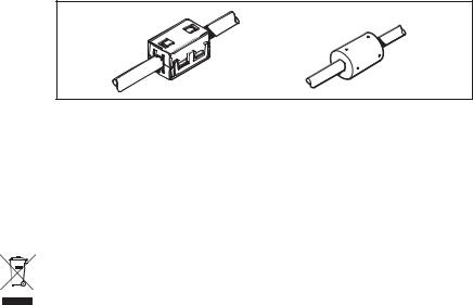
EMC suppression ferrites
The following illustration shows typical cable suppression ferrites used with Raymarine equipment. Always use the ferrites supplied by Raymarine.
D3548-6
Connection to other equipment
If your Raymarine equipment is to be connected to other equipment using a cable not supplied by Raymarine, a suppression ferrite MUST always be attached to the cable near to the Raymarine unit.
Waste Electrical and Electronic (WEEE) Directive
The WEEE Directive requires the recycling of waste electrical and electronic equipment. Whilst the WEEE Directive does not apply to some of Raymarine’s products, we support its requirements as par t of our environmental policy and we as you to be aware of how you should dispose of this product. The crossed out
wheelie bin symbol found on our products signifies that it should not be disposed of in general waste or landfill. Please contact your local dealer, national distributor or Raymarine Technical Services for information on product disposal.
SmartPilot Verado Installation and Commissioning Guide |
v |
|
|
Handbook information
To the best of our knowledge, the information in this handbook was correct when it went to press. However, Raymarine cannot accept liability for any inaccuracies or omissions it may contain. In addition, our policy of continuous product improvement may change specifications without notice. As a result, Raymarine cannot accept liability for any differences between the product and the handbook.
vi |
SmartPilot Verado Installation and Commissioning Guide |
|
|

SmartPilot Verado Installation and Commissioning Guide |
vii |
Contents |
|
Important information .......................................................................................... |
i |
About the documentation provided ........................................................................... |
i |
Safety notices ........................................................................................................... |
ii |
EMC guidelines ........................................................................................................ |
iii |
Waste Electrical and Electronic (WEEE) Directive ..................................................... |
iv |
Handbook information ............................................................................................. |
v |
Welcome .................................................................................................................. |
1 |
Introduction .............................................................................................................. |
1 |
Installation .............................................................................................................. |
3 |
Install the course computer ...................................................................................... |
4 |
Install the SmartPilot controller ................................................................................ |
6 |
Install the fluxgate compass ................................................................................... |
10 |
Mount the Type 1 pump .......................................................................................... |
12 |
Wiring the course computer .................................................................................... |
15 |
SmartPilot computer NMEA inputs/outputs ............................................................ |
19 |
Connect the hydraulic lines ..................................................................................... |
22 |
Commissioning ..................................................................................................... |
24 |
Dockside checks ..................................................................................................... |
24 |
Seatrial calibration ................................................................................................. |
30 |
SmartPilot settings .............................................................................................. |
36 |
Calibration basics ................................................................................................... |
36 |
Accessing the calibration modes ............................................................................ |
37 |
Display calibration screens ..................................................................................... |
38 |
User calibration ...................................................................................................... |
40 |
Seatrial calibration ................................................................................................. |
41 |
Dealer calibration ................................................................................................... |
41 |
Dealer calibration screens and settings .................................................................. |
41 |
System reset ........................................................................................................... |
48 |
Dealer calibration defaults ...................................................................................... |
49 |
Fault finding & maintenance .............................................................................. |
50 |
Fault finding ............................................................................................................ |
50 |
SmartPilot alarm messages .................................................................................... |
51 |
Maintenance .......................................................................................................... |
52 |
Specifications ....................................................................................................... |
54 |
Special tools ........................................................................................................... |
55 |
viii |
SmartPilot Verado Installation and Commissioning Guide |
|
|
SmartPilot Verado Installation and Commissioning Guide |
1 |
|
|
Welcome
Congratulations on having bought a Raymarine SmartPilot Verado. This product is designed to be installed on boats with a single helm, fitted with one or two Mercury Verado outboard engines. This system provides automatic control of your boat’s steering system.
SmartPilot Verado system components
S1G Course
Computer
Type1 Pump
ST6002 SmartPilot
Controller
Fluxgate compass
D8555-1
Introduction
The installation procedures are described in a logical sequence, but because of variations in boat design, space available etc, you may need to adapt the sequence to suit your particular circumstances.
Before you start fitting the SmartPilot system, we recommend you:
•Unpack and check that all parts are present
•Plan your installation so that you can fit the components in the best possible locations whilst taking account of cable/hose lengths and routes
2 |
SmartPilot Verado Installation and Commissioning Guide |
|
|
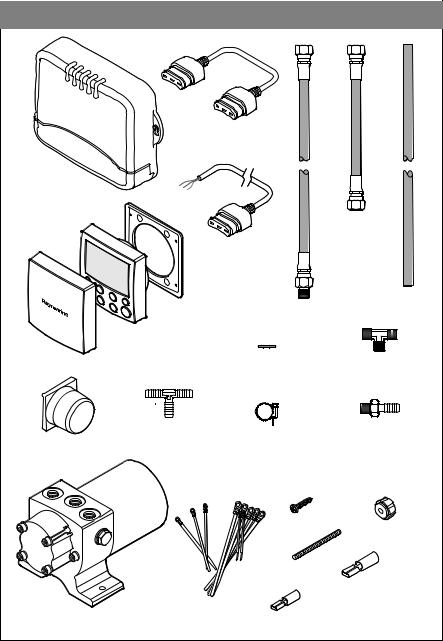
What's in the box
Course computer
SmartPilot controller
Sun Cover
Fluxgate compass
Type 1 Pump
SeaTalk Cable 1' (0.3 m)
Hydraulic hose (x2) 1' (305 mm)
SeaTalk Cable 30' (9 m)
|
|
Hydraulic hose |
Gasket |
Hydraulic hose (x 2) |
3' (915 mm) |
|
3' (915 mm) |
|
|
Sealing washer (x3) |
'T' connector |
|
|
9/16 UNF (x 2) |
Hose barb 'T' |
Hose barb to 1/4" BSP |
|
connector |
Hose clamp (x4) |
connector |
|
Screw (x2) |
Thumb nut (x2) |
|
|
|
|
|
|
Stud (x2) |
|
|
|
|
1/4" Spade connector |
|
Miscellaneous |
|
|
|
cable ties |
1/8" Spade connector (x2) |
-1 |
|
|
D8541 |
||
|
|
|
|
SmartPilot Verado Installation and Commissioning Guide |
3 |
|
|
Installation
In order to make the installation as trouble free as possible, we recommend you spend adequate time planning the best locations for your SmartPilot components. This is particularly important when considering the position of the Type 1 pump, as hydraulic hoses are supplied in fixed lengths, so there are some limitations on the positioning of the pump with respect to the boat’s helm.
The recommended installation sequence is as follows:
•install the course computer, page 4
•install the SmartPilot controller, page 6
•install the fluxgate compass, page 10
•wire the course computer, page 15
•mount the Type 1 pump, page 12
•connect the hydraulic lines, page 22
•bleed the hydraulic circuit, page 28
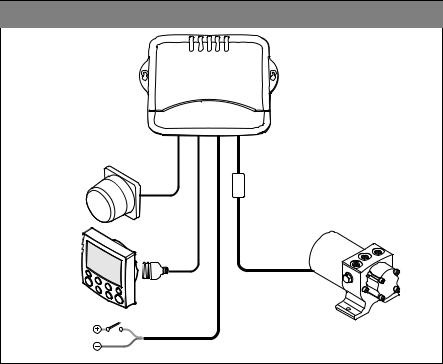
Component wiring
Course computer
Fluxgate |
SeaTalk |
Power |
Motor |
Fluxgate compass
SmartPilot
controller
Type 1 Pump
Power supply
D8543-1
4 |
SmartPilot Verado Installation and Commissioning Guide |
|
|
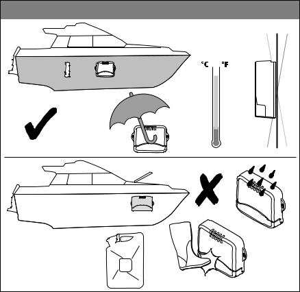
Install the course computer
Mount the course computer on a vertical surface, away from danger of physical damage or water ingress. Ensure that the planned position of the display and compass will allow sufficient length of cable to reach the course computer terminals. The Type 1 pump cable may be extended if required, see page 15.
Location
10˚ 10˚
or
MAX 55 130
MIN  -10 14
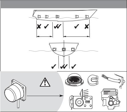
Do not fit near fuel tanks or in any other area where fuel vapor is likely.
D8544-1
SmartPilot Verado Installation and Commissioning Guide |
5 |
|
|
Drilling |
|
|
|
|
|
|
Check |
x2 |
|
|
|
|
|
|
Check |
|
|
Vertical |
|
x2 |
|
|
|
|
|
|
D8584-1 |
Mounting |
|
|
|
1 |
|
2 |
3 |
|
6 |
mm |
|
|
minimum |
|
|
|
|
|
D8585-1 |

6 |
SmartPilot Verado Installation and Commissioning Guide |
|
|
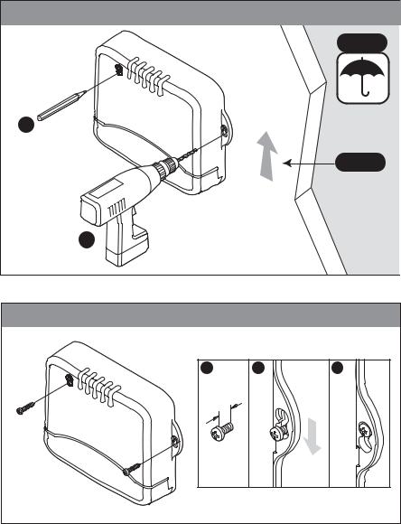
Install the SmartPilot controller
Location |
|
Check |
|
Check |
|
|
Min 0.8m (2ft 6in) |
Check |
1- |
|
D8586 |
SmartPilot Verado Installation and Commissioning Guide |
7 |
|
|
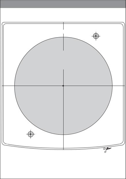
Controller template
Control Unit: |
|
Drill 5 mm (3/16 in) |
Surface mount template |
TOP |
diameter hole |
|
|
Machine hole 90 mm (3.55 in) diameter
Remove shaded areas only
Sun cover  edge
edge
Instrument  edge
edge
Drill 5 mm (3/16 in) diameter hole
D8547-1
8 |
SmartPilot Verado Installation and Commissioning Guide |
|
|
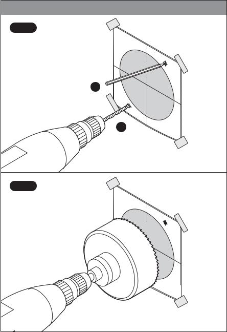
Drilling |
|
|
|
|
|
|
|
|
|
Step 1 |
Control |
|
|
|
|
|
|
|
|
|
|
|
|
|
|
|
|
||
|
Surface Unit: |
|
|
|
|
|
|
||
|
|
mou |
|
|
|
|
|
|
|
|
|
nt |
|
|
|
|
|
|
|
|
|
|
template |
|
|
|
|
|
|
|
|
|
|
|
TOP |
|
|
Drill5 |
|
|
|
|
|
|
|
|
|
mm |
|
|
|
|
|
|
|
|
|
|
|
|
|
|
|
|
|
|
|
diameter(3/16 |
|
|
|
|
90 |
|
|
|
|
holein) |
|
|
|
|
|
Machine |
|
|
|
|
|
|
|
|
Remove |
|
mm (3.hole |
|
|
||
|
|
|
|
55 |
in) |
|
|
||
|
|
|
|
diameter |
|
|
|||
|
|
|
|
shaded |
areas |
|
|
||
|
|
|
|
|
|
only |
|
||
|
|
|
|
|
|
|
|
|
|
|
x2 |
|
|
|
|
|
|
|
|
|
|
Drill5 |
mm |
|
|
|
|
|
|
|
|
|
|
|
|
|
|
|
|
|
|
diameter(3/16 |
|
|
|
|
|
|
|
|
|
|
holein) |
|
|
|
|
|
|
|
|
x2 |
|
|
|
|
|
|
|
Step 2 |
Control |
|
|
|
|
|
|
|
|
|
|
|
|
|
|
|
|
||
|
Surface Unit: |
|
|
|
|
|
|
||
|
|
mou |
|
|
|
|
|
|
|
|
|
nt |
|
|
|
|
|
|
|
|
|
|
template |
|
|
|
|
|
|
|
|
|
|
|
TOP |
|
|
Drill5 |
|
|
|
|
|
|
|
|
|
mm |
|
|
|
|
|
|
|
|
|
|
|
|
|
|
|
|
|
|
|
diameter(3/16 |
|
|
|
|
90 |
|
|
|
|
holein) |
|
|
|
|
|
Machine |
|
|
|
|
|
|
|
|
Remove |
|
mm (3.hole |
|
|
||
|
|
|
|
55 |
in) |
|
|
||
|
inch) |
|
|
diameter |
|
|
|||
|
|
|
shaded |
|
|
|
|
||
|
(3.56 |
|
|
areas |
|
|
|||
|
|
|
|
|
only |
|
|||
|
mm |
|
|
|
|
|
|||
|
|
|
|
|
|
|
|
||
|
90.6 |
|
|
|
|
|
|
|
|
|
|
|
|
|
|
|
|
|
|
|
|
Drill5 |
mm |
|
|
|
|
|
|
|
|
|
|
|
|
|
|
|
|
|
|
diameter(3/16 |
|
|
|
|
|
|
|
|
|
|
holein) |
|
|
|
|
|
|
|
|
|
|
|
|
|
|
|
1-D8587 |
SmartPilot Verado Installation and Commissioning Guide |
9 |
|
|
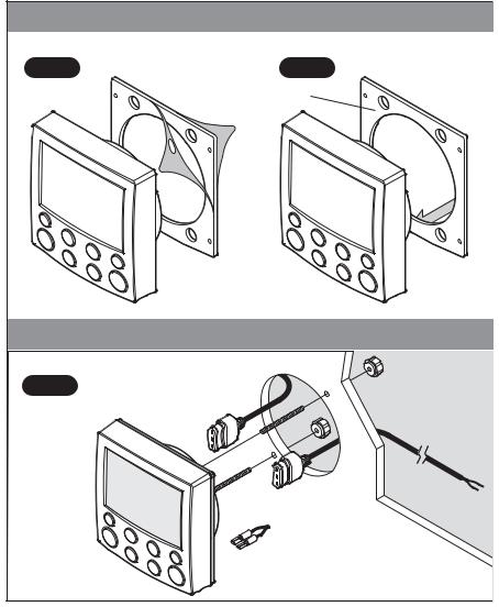
Sealing
Step 3 |
Step 4 |
Sticky side 
Mounting
Step 5
SeaTalk cable 1' (0.3 m)
to optional SeaTalk instrument
SeaTalk cable 30' (9 m) to Course computer
 1/8" Spade connectors
to optional NMEA instrument
1-D8546
10 |
SmartPilot Verado Installation and Commissioning Guide |
|
|
Install the fluxgate compass
The fluxgate compass is supplied with a 26’ (8m) cable. Before mounting the compass, ensure that you have sufficient cable to reach the course computer. The compass must be mounted with the cable vertically downward.
Location |
|
30% |
50% |
Min 1m (3ft 3in) |
|
|
D8588-1 |
SmartPilot Verado Installation and Commissioning Guide |
11 |
|
|
Drilling |
|
|
|
|
x4 |
|
|
Vertical |
|
|
|
|
|
|
x4 |
|
|
Vertical |
|
Mounting |
|
|
|
|
|
|
! |
|
|
|
COM |
PASS |
|
|
|
|
AREA |
|
|
|
|
|
|
|
|
Cable at bottom |
-1 |
||
|
D8589 |
|||
12 |
SmartPilot Verado Installation and Commissioning Guide |
|
|
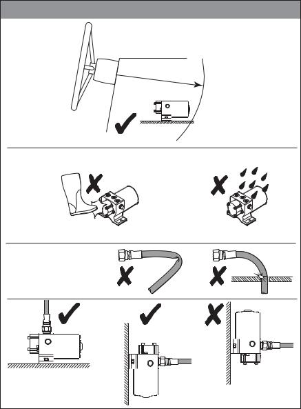
Mount the Type 1 pump
Mount the Type 1 pump within 3’ 3” (1 m) of the helm, on a structural member to avoid vibration that could damage the hydraulic pipes. Secure the pump using 1/4” (M6) stainless steel bolts, nuts and lock washers, or self tapping screws and lock washers.
Location
Location of the pump using the supplied hoses.
Max |
(3ft 3in) |
|
|
1m |
|
||
|
|
Note: Pump may be placed |
|
Type 1 pump |
elsewhere if Mercury |
||
extension hoses are used. |
|||
|
|
||
Provide protection |
Install in a dry location. |
||
from physical |
|
|
|
damage. |
|
|
|
No sharp bends, kinks or chafing of tube.
Mount pump either horizontally or with connector end up.
Do not mount pump
with connector end down.
D8545-1
Loading...