

Page 1

20-522b.fm Page 1 Thursday, September 7, 2000 9:41 AM
PRO-92
Handheld Scanner
Owner’s Manual
Please read before using this equipment.
Page 2

20-522b.fm Page 2 Thursday, September 7, 2000 9:41 AM
Contents
ˆ
Features .................................................................... 5
FCC Notice .............................. ..... ...... ..... ...... ...... 8
Scanning Legally ................................................. 8
Preparation ............................................................... 9
Power Sources .................................................... 9
Using Batteries .......................................... 10
Charging Rechargeable Batte ries .............. 12
Using AC Power ......................................... 13
Using Vehic le Power .................................. 14
Connecting the Antenna ................................... 15
Connecting an Optional Antenna ............... 15
Connecting an Earphone/Hea dph one s ............. 16
Listening Safely ......................................... 16
Traffic Safety .............................................. 17
Connecting an Extension Speaker .................... 17
Using the Belt Clip ............................................. 17
Connecting the Clone Cable ............................. 18
About Your Scanner ............................................... 18
A Look at the Keypad ........................................ 19
A Look at the Display ........................................ 21
Understanding Banks ........................................ 22
Channel Storage Banks ............................. 22
Search Banks ............................................ 23
Understanding CTCSS/DCS ............................. 23
PL Codes ................................................... 23
DPL Codes ................................................ 23
Understanding Your Scanner’s Modes .............. 24
Open and Closed Modes ........................... 24
AM Mode ................................................... 25
FM Mode .................................................... 26
LTR (E. F. Johnson) Mode ......................... 26
Motorola Mode ........................................... 27
EDACS Mode ............................................ 28
© 2000 Tandy Corporation.
RadioShack, RadioShack.com, and Adaptaplug are
registered tradem ar ks us ed by Tandy Corporation.
Hypersearch and Hyperscan are trademarks
LTR is a regi stered trademark of EF Johnson.
are registered trademarks of Motorola Inc.
EDACS is a registered trademark of GE/Ericsson Inc.
2
All Rights Reserved.
used by Tandy Corporation.
Motorola, Smartnet and Privacy Plus
Contents
Page 3

20-522b.fm Page 3 Thursday, September 7, 2000 9:41 AM
Operation ................................................................. 29
Turning on the Scanner and Setting Squelch .... 29
Storing Known Frequencies into Channels ....... 30
Storing Text Tags ............................................... 31
Assigning a Text Tag to a Channel ............. 31
Assigning a Text Tag to a Bank .................. 32
Text Input Chart ............................ ...... ...... .. 33
Finding and Storing Active Frequencies ............ 34
Searching a Preprogrammed
Frequency Range ............................... ........ 34
Storing a Frequency While Searching
for a Specified Channel .............................. 36
Changing a Search Range with a
Preprogrammed Range .............................. 36
Manually Changing a Search Range .......... 37
Scanning the Channels ..................................... 37
Turning Channel-Storage Banks
Off and On .................................................. 38
Manually Tuning a Frequency ........................... 38
Deleting Frequencies from Channels ................ 39
Listening To the Weather Band ......................... 39
Listening to a Weather Channel ................. 39
Displaying Weather Messages ................... 39
Special Features ..................................................... 40
Using the Delay Function .................................. 40
Locking Out Channels or Frequencies .............. 41
Locking Out Channels ................................ 41
Reviewing the Lock-Out Channels ............. 41
Locking Out Frequencies ........................... 41
Reviewing Locked-Out Frequencies .......... 42
Clearing a Locked-Out Frequency ............. 42
Clearing All Lock Out Frequenc ies
in a Search Bank ........................................ 42
Priority ............................................................... 43
Changing the Receive Mode ............................. 45
Changing the Frequency Step ........................... 45
Using the Attenuator .......................................... 46
Using the Display Backlight ............................... 47
Turning the Key Tone On and Off ...................... 47
Using the Keylock .............................................. 47
Changing the Display Contrast .......................... 47
Cloning the Programmed Data
from Scanner to Scanner ................................... 48
Contents
3
Page 4

20-522b.fm Page 4 Thursday, September 7, 2000 9:41 AM
Trunking Operation ................................................ 48
Understanding Trunking .................................... 49
Setting Squelch for the Trunking Mode ............. 50
Programming Trun ki ng Frequencies ................. 50
Programming Motorola Trunking
Systems (UHF-Lo) ..................................... 51
Programming Fleet Maps .................................. 53
Talk Group IDs .................................................. 54
Storing Talk Group IDs ............................... 55
Talk Group ID Hold ..................................... 55
Locking Out Talk Group IDs ....................... 56
Reviewing Locked-Out Talk Group IDs ...... 56
Clearing Talk Group IDs ............................. 56
Clearing All Talk Group IDs in One Bank ... 56
Open and Closed Modes .................................. 57
Changing the Open/Closed Mode .............. 58
A General Guide to Scanning ................................ 58
Guide To Frequenci es ....................................... 59
US Weather Frequencies ........................... 59
Ham Radio Frequencies ............................ 59
Birdie Frequencies ..................................... 59
Guide to the Action Bands ................................ 61
Typi ca l Band Usag e ................................... 61
Primary Usage ........................................... 61
Band Allocation ................................................. 62
Frequency Conversion ...................................... 65
Troubleshooting ..................................................... 66
Resetting/Initializing the Scanner ...................... 67
Resetting the Scanner ............................... 67
Initializing the Scanner ............................... 68
Care ......................................................................... 68
Specifications ......................................................... 69
4
Contents
Page 5

20-522b.fm Page 5 Thursday, September 7, 2000 9:41 AM
Features
ˆ
Your RadioShack Handheld Scanner is one of a new
generation of scanners desig ned to track Motorol a
I and Type II (such as Smartnet
hybrid analog trunking systems, plus GE/Ericsson
(EDACS®) and EF Johnson (LTR®) type systems, wh ich
are extensively used in many communication systems.
Trunking comm uni ca tions systems let a large group of 2way radio users (or even different groups of 2-way radio
users) efficiently use a set of frequencies. Instead of selecting a specific frequency for a transmission, the user
simply selects a talk group. The trunking system automatically transmits the call on the first available frequency, and also sends a code that uniquely identifies that
transmission .
Since the trunking system might send a call and its response on different frequencies, it is difficult to listen to
trunked communications using a regular scanner. The
scanner monitors the data sent with a 2-way radio transmission, so you can hear the call and response for that
user and more easily “follow” the conversation.
The scanner also lets you scan conventional transmissions, and is preprogrammed with service search banks
for convenience. By pressing a single button, you can
quickly search those frequencies most commonly used
by public service an d o t he r ag enc ie s w i tho ut t edi ous an d
complicated programming.
®
and Privacy Plus®) and
®
Type
This scanner gives you direct access to over 33,000 frequencies including those used by police and fire departments, ambulance services, government agencies, air,
and amateur radio services.
Your scanner includes these features:
Simultaneous Trunking Operation
trunking systems (LTR, Motorola, and EDACS) and conventional systems at the same time.
10 Channel-Storage Banks
nels in each bank (500 channels) to group channels so
calls are easier to identify.
— let you store 50 chan-
Features
— tracks three
5
Page 6

20-522b.fm Page 6 Thursday, September 7, 2000 9:41 AM
12-Character, 4-Line, Dot-Matrix Display
— shows
you detailed operating information and lets you easily
program the scanner.
Weather Alert
— automatically soun ds th e alarm tone to
advise of hazardous weather conditions when it detects
the alert signal on the local National Oceanic and Atmospheric Administration (NOAA) weather channel during
priority operation.
Digital Weather Alert
— displays the weather event text
so you can see the reason for the alert.
Preprogrammed Frequency Ranges
— let you search
for transmissions within preset frequency ranges or within ranges you set, to re duce sear ch ti me and selec t interesting frequencies more quickly.
Subaudible Tone Decode
— decodes and displays the
Continuous Tone Coded Squelch System (CTCSS) tone
signal being transmitted.
Digital Subaudible Tone Decode
— decodes and dis-
plays the Digital Coded Squelch (DCS) being received.
Data Cloning
— lets you transfer the programmed data
to another PRO-92 scanner. You can also upload or
download th e programmed data to or from a PC us ing
an optional interface kit.
Triple Conversion Superheterodyne Receiver
— virtually eliminates any interference from intermediate frequency (IF) images, so you hear only the frequency you
select.
Hyperscan
TM
and Hypersearch
TM
— the scanner scans
at up to 25 channels per second and searches at up to
50 steps per second, to help you quickly find interesting
transmission s.
Scan Delay
— delays scanning for about 2 seconds before moving to another channel in conventional mode, so
you can hear more replies that are made on the same
channel.
6
Features
Page 7

20-522b.fm Page 7 Thursday, September 7, 2000 9:41 AM
Priority Channel
— you can set the scanner to check
one channel every 2 seconds so you do not miss important calls.
Signal Attenuation (Attenuate)
— lets you program
each memory loca tio n to reduce the scan ner’ s se ns iti vit y
to strong local signals, to reduce interference or noise
caused by these signals.
Text Input
— lets you input a text label for each channel, talk group ID, bank, or other memory loc ation so yo u
can easily know about the transmission you are hearing.
Lock Out Function
— lets you set your scanner to skip
over specified channels or frequencies when scanning
or searching, and skip over IDs when tracking trunked
systems.
Key Lock
— lets you lock the scanner’s keys to help
prevent accidentally changing the scanner’s programming.
Flexible Antenna with BNC Connector
— provides excellent reception and is designed to help prevent antenna breakage.
Memory Backup
— keeps the frequencies stored in
memory for an extended time even without internal batteries.
Three Power Options
— let you power the scanner with
internal batteries (non-rechargeable batteries or rechargeable batteries). You can also use an AC adapter
(not supplied) or power the scanner in a vehicle using a
DC adapter (not supplied).
Supplied Police Call Trunking Guide
— provides a
quick reference to pu blic safet y trunki ng radio syste ms in
the United States.
Your scanner can receive these frequencies:
• 29–54 MHz
• 108–136.9875 MHz
• 137–174 MHz
Features
7
Page 8

20-522b.fm Page 8 Thursday, September 7, 2000 9:41 AM
• 380–512 MHz
• 806–823.9875 MHz
• 849–868.9875 MHz
• 894–960 MHz
This Owner’s Manual also includes the section “A General Guide to Scanning” on Page 58 to help you target
frequency ranges in yo ur servi ce area so you can se arch
for a wide variety of transmissions.
FCC NOTICE
Your scanner might cause TV or radio interference even
when it is operating prope rly . To de term in e whether your
scanner is causing the interference, turn off your scanner. If the interfere nce goes aw ay, your scanner is causing the interference. Try the following methods to
eliminate the interference.
• Move your scanner away from the TV or radio.
• Connect your scanner to an outlet that is on a differ-
ent electrical circuit from the TV or radio.
• Contact yo ur local Radio Shack store for help.
If you cannot eliminate the interference, the FCC requires that you stop using your scanner.
This device complies with Part 15 of the
eration is subject to the following conditions: (1) this device must not cause harmful interference, and (2) this
device must accept any interference received, including
interference that may cause undesired operation.
Note:
Mobile use of this scanner is unlawful or requires
a permit in some areas. Check the laws in your area.
FCC Rules
. Op-
SCANNING LEGALLY
Scanning is a fun and interesting hobby. You can hear
police and fire departments, ambulance services, government agencies, private companies, amateur radio
services, aircraft, a nd m ilita ry operations. It is legal to li s-
8
Features
Page 9

20-522b.fm Page 9 Thursday, September 7, 2000 9:41 AM
ten to almost every transmission your scanner can receive. However, there are some electronic and wire
communications that are illegal to intentionally intercept.
These include:
• telephone conversations (cellular, cordless, or other
private means of telephone signal transmission)
• pager transmissions
• scrambled or encrypted transmissions
According to the
vacy Act
possibly imprisoned for intentionally listening to, using,
or disclosing the contents of such a transmission unless
you have the consent of a party to the communication
(unless such activity is otherwise illegal). These laws
change from time to time and there might be state or local laws that also affect legal scanner usage.
ˆ
(ECPA), as amended, you could be fined and
Preparation
Federal Electronic Comm unica tions Pri-
POWER SOURCES
You can power your scanner from any of three sources:
• internal non-rechargeable batteries or rechargeable
batteries (not supplied — see “Using Batteries” on
Page 10)
• standard AC power (with an optional AC adapter —
see “Using AC Power” on Page 13)
• vehicle power (with an optional DC adapter — see
“Using Vehicle Power” on Page14)
Notes:
• Connecting an AC or DC ada pter to th e scanne r di sconnects internal batteries when you use the supplied non-rechargeable battery holder, but it does
not disconnect internal batteries when you use the
supplied rechargeab le batt ery holde r.
Preparation
9
Page 10
20-522b.fm Page 10 Thursday, September 7, 2000 9:41 AM
• If you install the rechargeable battery holder, you
can operate the scanner and recharge the
rechargeable batte ries at t he same ti me. See “Using
Batteries” below and “Charging Rechargeable Batteries” on Page 12.
• If the scanner stops working properly after connecting it to power, try resetting it. See “Resetting/Initializing the Scanner” on Page 67.
Using Batteries
You can power the scann er with si x AA batteri es. For th e
longest operatio n and b es t performance, we rec ommend
alkaline batteries, available at your local RadioShack
store.
You can use either the supplied non-rechargeable black
battery holder, or the supplied rechargeable yellow battery holder. If you use the rechargeable battery holder,
we recommend RadioShack nickel-cadmium or nickelmetal hydride batteries.
Warning:
Never install no n-re ch arge able batteries in th e
rechargeable yellow battery holder. Non-rechargeable
batteries can get hot or explode if you try to recharge
them.
Note:
You must charge rechargeable batteries before
you use them the first time. See “Charging Rechargeable Batteries” on Page 12.
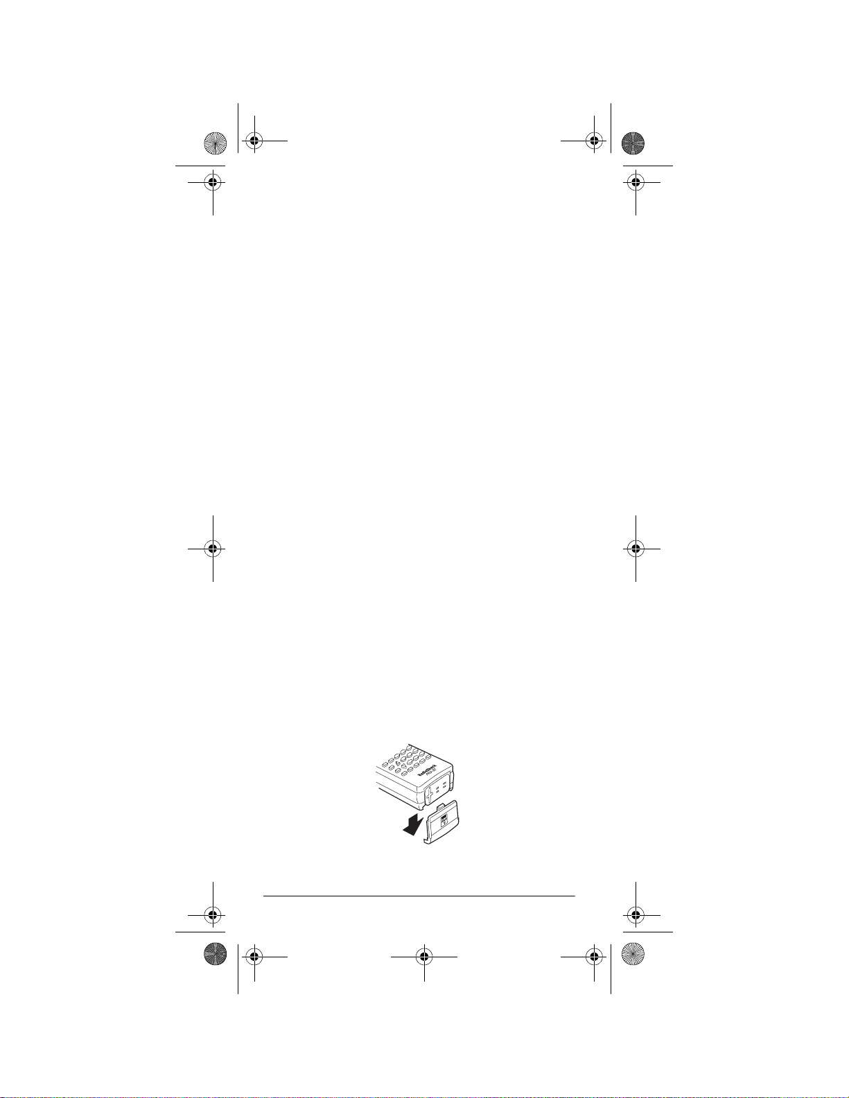
Follow these steps to install the batteries.
1. Press down on the battery compartment cover on
the bottom of the scanner and slide the cover in the
direction of the arrow to remove it.
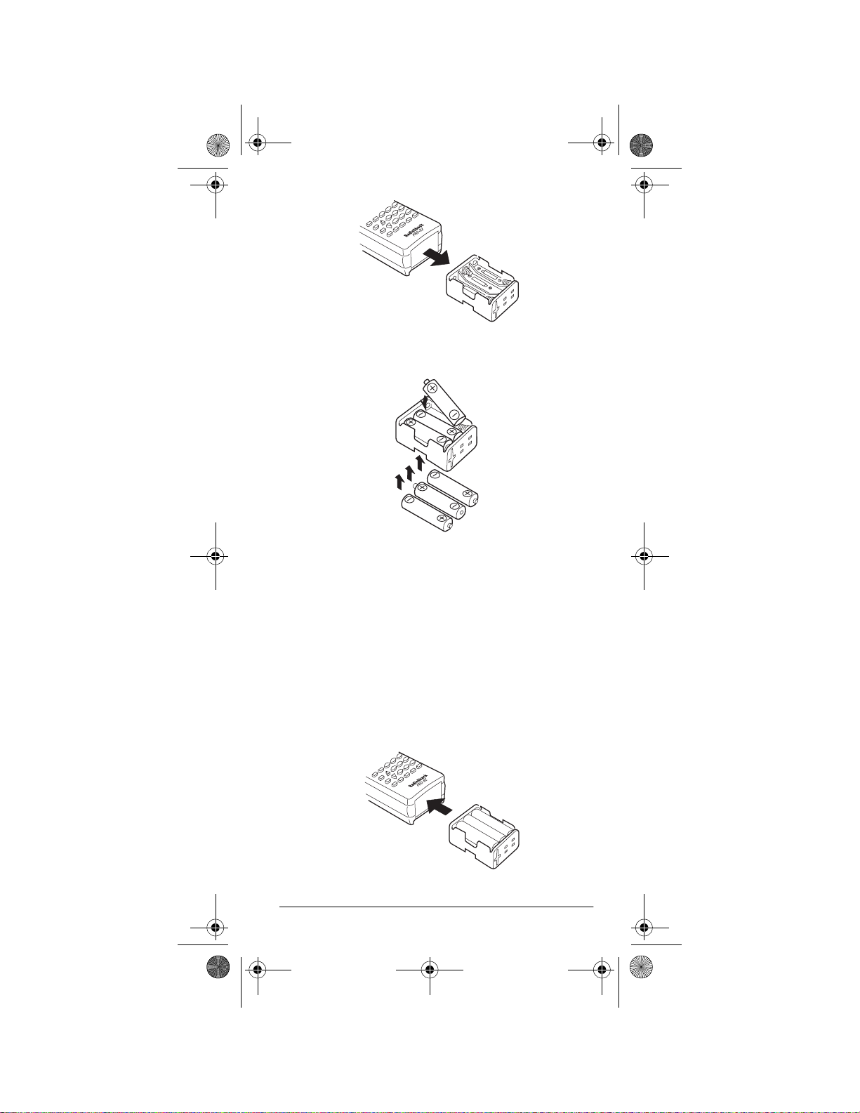
2. Pull out and slide the battery holder out of the battery compartment.
10
Preparation
Page 11
20-522b.fm Page 11 Thursday, September 7, 2000 9:41 AM
3. Insert six AA batteries in the battery holder as indicated by the polarity symbols (+ and –) marked on
the holder.
Cautions:
• Use only fresh batteries of the required size and
recommended type.
• Always remove old or weak batteries. Batteries
can leak chemicals that destroy electronic circuits.
• Do not mix old and new batteries, different types
of batteries (alkaline or rechargeable), or
rechargeable batteries of different capacities.
4. Slide the battery holder into the compartment.
Preparation
11
Page 12

20-522b.fm Page 12 Thursday, September 7, 2000 9:41 AM
Caution:
The battery holder fits only one way. Do
not force it.
5. Replace the cover.
When battery power is low,
Low Battery!
appears
and the scanner beeps continuously. When battery power is depleted, the scanner turns itself off. Replace all six
non-rechargeable batteries, or recharge the rechargeable batteries. See “Charging Rechargeable Batteries.”
Warning:
Always dispose of old batteries promptly and
properly. Do not bury or burn them.
Caution:
If you do not plan to use the scanner with batteries for a month or lon ger, remove the ba tteries . Batteries can leak chemicals that can destroy electronic parts.
Charging Rechargeable Batteries
Your scanner has a built-in charging circuit that lets you
charge rechargeabl e batt erie s (no t su ppl ied ) wh il e it is in
the scanner. To charge rechargeable batteries connect
an appropriate AC or DC adapter to the
PWR DC 9V
We recommend RadioShack rechargeable batteries.
Note:
To charge batteries with a DC adapter from a DC
power source, you must use RadioShack Cat. No. 2731825 and a size H Adaptaplug
®
(neither supplied) available at your local RadioShack store. Make sure the
adapter’s voltage is set to 10V.
jack.
It takes between 14–16 hours to recharge rechargeable
batteries that are fully discharged. You can operate the
scanner while recharging the rechargeable batteries, but
charging takes longer.
Notes:
• The scanner can charge Ni-MH batteries, however,
these batteries require more than 24 hours to
charge. We recommend using an external quick
charger for Ni-MH batteries.
• Additional charging time is required for highcapacity rechargeable batteries.
12
Preparation
Page 13

20-522b.fm Page 13 Thursday, September 7, 2000 9:41 AM
• Rechargeable batteries last longer and deliver more
power if you le t them ful ly discha rge onc e a month.
To do this, use the scanner until
appears. Then fully charge the rechargeable batteries.
Low Battery!
Important:
tery Recycling Seal on the nickel-cadmium
(Ni-Cd) battery indicates RadioShack is
voluntarily participating in an industry program to collect and recycle these batteries
at the end of their use ful life , when tak en out o f servi ce in
the United States or Canada. The RBRC program provides a convenient alternative to placing use d Ni-C d batteries into the trash or the m unici pal w aste strea m, w hich
may be illegal in your area. Please call 1-800-THESHACK (1-800-843-7422) for information on Ni-Cd battery recycling and disposal bans/restrictions in your area. RadioShack’s involvement in this program is part of
the company’s commitment to preserving our environment and conserving our natural resources.
.The EPA certified RBRC® Bat-
Using AC Power
You can power the scanner using an 9V, 300 mA AC
adapter and a size H Adaptaplug (neither supplied). We
recommend Radio S ha ck Cat. No. 273-1767 (available at
your local RadioShack store).
Cautions:
You must use a Clas s 2 po we r so urc e th at
supplies 9V DC and delivers at least 300
!
mA. Its center tip must be set to negative
and its plug must fit the scanner's
Using an adapter that does not meet these specifications could damage the scanner or the adapter.
• Always connect the AC adapter to the scanner
before you connect it to AC power. When you finish,
disconnect the adapter from AC power before you
disconnect it from the scanner.
PWR DC 9V
jack.
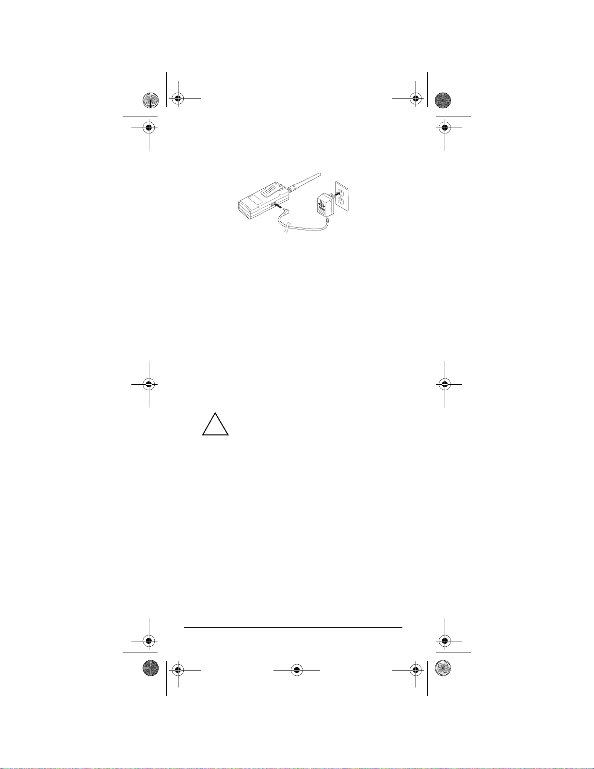
Follow these steps to connect the adapter.
1. Connect the Adaptaplug to the adapter’s cord with
the tip set to negative.
Preparation
13
Page 14
20-522b.fm Page 14 Thursday, September 7, 2000 9:41 AM
2. Plug the adapter’s barrel plug into the scanner’s
PWR DC 9V
3. Plug the adapter into a standard AC outlet.
jack.
Using Vehicle Power
You can power the scanner from a vehicle’s 12V power
source (such as a cigarette-lighter socket) using a 9V,
300 mA DC adapter and a size H Adaptaplug (neither
supplied). We recommend RadioShack Cat. No. 2731810 (available at your local RadioShack store).
Note:
For charging batter ies wit h an op tional DC a dapter
from a DC power source, use RadioShack Cat. No. 2731825 and a size H Adaptaplug (available at your local
RadioShack store). Make sure the adapter’s voltage is
set to 10V.
Cautions:
You must use a power source that supplies 9V DC and delivers at least 300 mA.
!
Its center tip must be set to negative and
its plug must fit the scanner's
ing an adapter that does not meet these specifications could damage the scanner or the adapter.
• Always connect the DC adapter to the scanner
before you connect it to the power source. When
you finish, disconnect the adapter from the power
source before you disconnect it from the scanner.
Follow these steps to connect the adapter.
1. Connect the Adaptaplug to the adapter’s cord with
the tip set to negative.
2. Plug the adapter’s barrel plug into the scanner’s
PWR DC 9V
14
jack.
Preparation
PWR DC 9V
jack. Us-
Page 15
20-522b.fm Page 15 Thursday, September 7, 2000 9:41 AM
3. Plug the adapter’s cigarette-lighter plug into your
vehicle’s cigarette-lighter socket.
Note:
If the scanner do es not operate properly w h en yo u
connect a DC adapter, unplug the DC adapter from the
cigarette-lighter socket and clean the socket to remove
ashes and other debris.
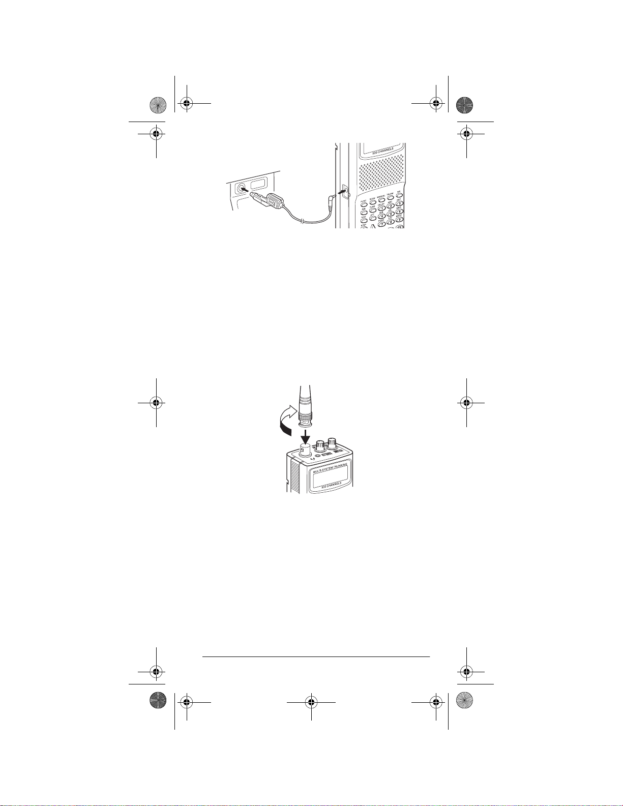
CONNECTING THE ANTENNA
Follow these steps to attach the supplied flexible anten-
ANT
na to the
jack on the top of your scanner.
1. Align the slots around the antenna’s connector with
the tabs on the
2. Press the antenna down over the jack and turn the
antenna’s base clockwise until it locks into place.
ANT
jack.
Connecting an Optional Antenna
The antenna connector on your scanner makes it easy
to use the scanner with a vari ety of a ntenna s, such a s an
external mobile antenna or outdoor base station antenna. Your local RadioShack store sells a variety of antennas.
Preparation
15
Page 16
20-522b.fm Page 16 Thursday, September 7, 2000 9:41 AM
Always use 50-ohm coaxial cable, such as RG-58 or
RG-8, to connect an outdoor antenna. For lengths over
50 feet, use RG-8 low-loss dielectric coaxial cable. If
your antenna’s cable does not have a BNC connector,
you will also need a BNC adapter (also available at your
local RadioShack store).
Follow the installat ion instr uctions sup plied wit h the antenna, route the antenna cable to the scanner, then con-
ANT
nect it to the
jack.
Warning:
moving an outdoor antenna. If the antenna starts to fall,
let it go! It could contact overhead power lines. If the antenna touches a power line, contact with the antenna,
mast, cable or guy wires can cause electrocution and
death! Call the power company to remove the antenna.
Do not attempt to do so yourself.
Use extreme caution when installing or re-
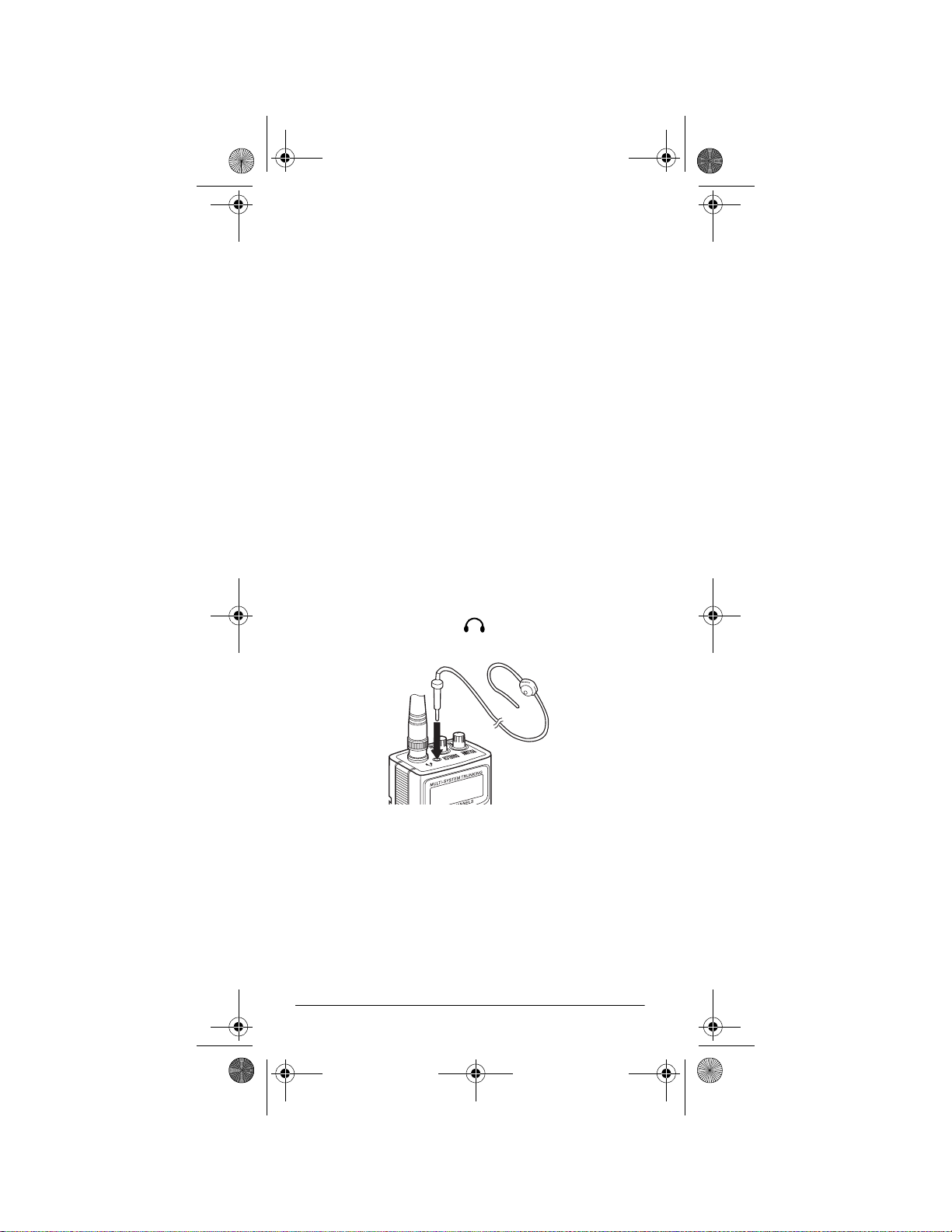
CONNECTING AN EARPHONE/
HEADPHONES
For private listening , you can plug an earph one or m on o/
stereo headphone s (not s upplied), available at y ou r l ocal
RadioShack store, into the jack on top of your scanner. This automatically disconnects the internal speaker.
Listening Safely
To protect your hearing, follow these guidelines when
you use an earphone or headphones:
• Do not listen at extremely high volume levels.
Extended high-volume listening can lead to permanent hearing loss.
16
Preparation
Page 17
20-522b.fm Page 17 Thursday, September 7, 2000 9:41 AM
• Set the volume to the lowest setting before you
begin listening. After you begin listening, adjust the
volume to a comfortable level.
• Once you set the volume, do not increase it. Over
time, your ears adapt to the volume level, so a volume level that does not caus e disco mfort might st ill
damage your hearing.
Traffic Safety
Do not wear an e arph one or headphone s whil e you drive
a vehicle or ride a bicycle. This can create a traffic hazard and can be illegal in some areas.
Even though some earphones and headphones let you
hear some outside sounds when you listen at normal
levels, they still can present a traffic hazard.
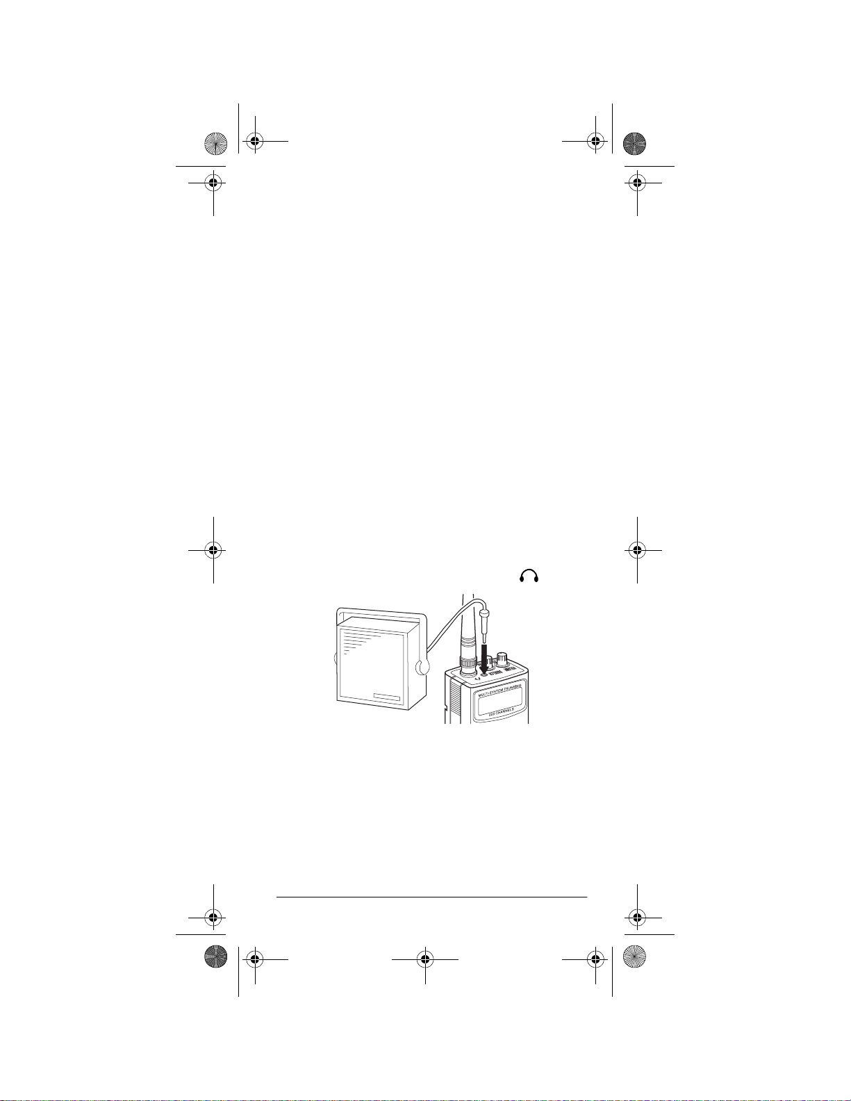
CONNECTING AN EXTENSION
SPEAKER
In a noisy area, an amplified speaker (not supplied),
available at your local RadioS hack store, might provide
more comfortable listening. Plug the speaker cable’s
inch (3.5-mm) mini-plug into your scanner’s jack.
1
/8-
Note:
You must use an am pli fied speaker with this s ca nner. Non-amplified speakers do not provide sufficient
volume for c omfortable listening.
USING THE BELT CLIP
You can use the belt clip attached to the back of the
scanner for hands-free carrying when you are on the go.
Slide the belt clip over your belt or waistband.
Preparation
17
Page 18

20-522b.fm Page 18 Thursday, September 7, 2000 9:41 AM
CONNECTING THE CLONE CABLE
You can transfer the programmed data to and from another PRO-92 or PRO-2067 using the supplied clone cable. Connect the cable between each scanner’s PC/IF
jacks. See “Cloning the Progr amm ed Da ta fro m Scann er
to Scanner” on Page 48. You can also upload or download the programmed data to or from a PC using an optional PC interface kit available by special order from
your local RadioShack store.
About Your Scanner
ˆ
Once you understand a few simple terms used in this
manual and familiarize yourself with your scanner’s features, you can put the scanner to work for you. You simply determine the type of communications you want to
receive, then set the scanner to scan them.
A
frequency
kHz or MHz). To find active frequen cies , you can use the
search function.
You can also search the SEARCH banks, which are preprogrammed frequencies in the scanner’s memory (see
“Searching a Preprogrammed Frequency Range” on
Page 34 for the frequency list). You can change the
SEARCH frequency ranges.
When you find a frequency, you can store it into a programmable memo ry location calle d a
grouped with your other channels in a
bank
see if there is activity on the frequencies stored there.
Each time the scanner finds an active frequency, it stays
on that channel until the transmission ends. See “Trunking Operation” on Page 48 for terms related to trunking
systems.
18
is the receiving si gna l locati on (ex presse d in
channel
. You can then scan the channel-storage banks to
About Your Scanner
, which is
channel-storage
Page 19
20-522b.fm Page 19 Thursday, September 7, 2000 9:41 AM
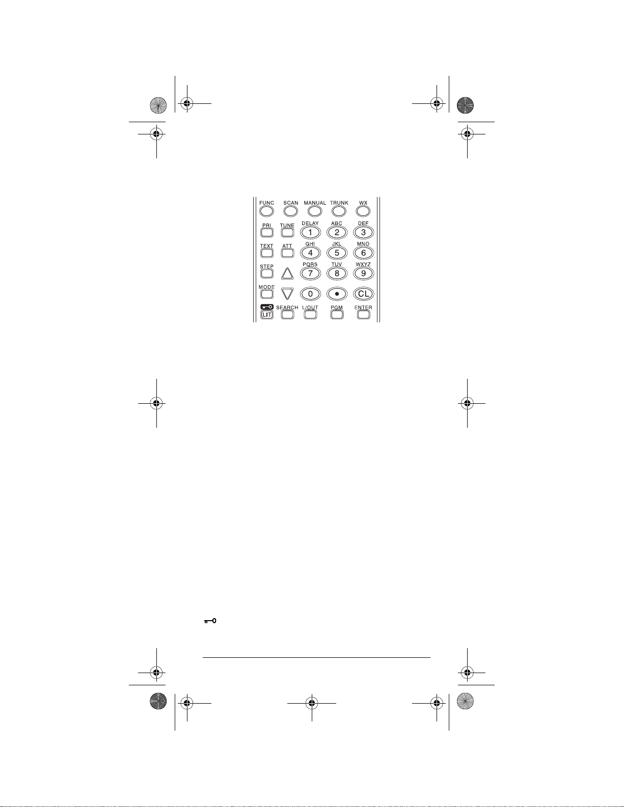
A LOOK AT THE KEYPAD
Your scanner’s keys might seem confusing at first, but
this information should help you understand each key’s
function.
FUNC
(function)
pressing this key along with other keys.
SCAN
— scans through the programmed channels.
— lets you use various functions by
MANUAL
— stops scanning and lets you directly enter a
channel number.
TRUNK
— stores the trunking ID code or holds the trunk-
ing ID while scanning.
WX
— scans through the 7 preprogrammed weather
channels.
PRI
(Priority)
— sets and turns the priority function on or
off.
TEXT
— lets you input text.
STEP
— changes the freque ncy st ep or dis play s step frequency during search, or selects PL or DPL codes when
programming.
MODE
— changes the receive mode (AM, FM, PL, DL,
LT, MO, ED). See “Changing the Receive Mode” on
Page 45.
LIT
(Light)
/
— turns on/off the display’s backlight or
locks/unlocks the keypad to prevent accidental entries.
About Your Scanner
19
Page 20

20-522b.fm Page 20 Thursday, September 7, 2000 9:41 AM
TUNE
— lets you input a frequency and allows you to
fine tune a frequency along with or .
ATT
(Attenuate)
— turns attenuation on to reduce the
scanner’s sensitivity, or turns it off to increase it.
or — selects the search direction during frequency
search or tuning.
SEARCH
L/OUT
— lets you search the ten search banks.
(Lock Out)
— lets you lock out a selected channel, skip a specified frequency during search, or lock out
a selected ID code.
PGM
— programs frequencies into channels.
ENTER
— lets you complete the entry of frequencies and
text.
1/DELAY
— enters a 1, or programs a 2-second delay for
the selected chan nel /se arc h b an k, or i np uts c hara cte rs 0
through 9.
2/ABC
— enters a 2, or inputs characters A, B, or C.
3/DEF
— enters a 3, or inputs characters D, E, or F.
4/GHI
— enters a 4, or inputs characters G, H, or I.
5/JKL
— enters a 5, or inputs characters J, K, or L.
6/MNO
— enters a 6, or inputs characters M, N, or O.
7/PQRS
— enters a 7, or inputs characters P, Q, R, or S.
8/TUV
— enters a 8, or inputs characters T, U, or V.
9/WXYZ
— enters a 9, or inputs characters W, X, Y, or Z.
0
— enters a z ero, or inputs c haracte rs., -, #, _, @, +,
*, &, /, '
— enters a decimal point (necessary when program-
•
ming frequencies), space, or hyphen (in Motorola type I
, $,%,!, ^, (,), ?, , `, and ^.
code setting).
CL
— clears an incorrect entry.
20
About Your Scanner
Page 21

20-522b.fm Page 21 Thursday, September 7, 2000 9:41 AM
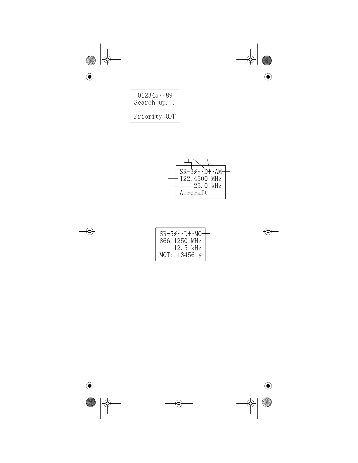
A LOOK AT THE DISPLAY
Bank 0–(9)
Manual Mode
Current Frequency
Current Bank
Bank 1
(M)anual Mode
(P)rogram
(S)can
(I)D Program
Receiving a Signal (
Priority Freq. (T)runked
Attenuate (
Delay (
Locked (
Out
Channel
00–(49)
Manual Mode (AM or FM)
Channel 00–(49)
Talk Group ID
Out
Note: If you enter the ID text
tag in an ID code, the scanner
displays it instead of the ID
code and
no signal)
•
no attenuation)
•
no delay)
Scanning Up)
•
Scanning Down)
(
Current
Mode is FM
Channel
Stored Text
(+) Open
(–) Closed
Motorola
Detecting a
Trunking or
Tone Signal
Code
.
Scan Mode
Bank Off
•
Selected for Scanning
+
in Open Mode
Selected for Scanning
–
in Closed Mode
About Your Scanner
21
Page 22
20-522b.fm Page 22 Thursday, September 7, 2000 9:41 AM
6 and 7 are turned off
Search Mode
Searching
Frequency
for Range
in Bank 3
Search Mode
Current Frequency
Stepping
Search Bank 5
Delay Scanning Up
AM
Search Mode
Motorola
UNDERSTANDING BANKS
Channel Storage Banks
To make it easier to identify and select the channels you
want to listen to, channels are divided into 10 banks (0–
9) of 50 (00 to 49) channels each. Use each channelstorage bank to group frequencies, such as those used
by the police department, fire department, ambulance
services, or aircraft (see “Typical Band Usage” on
Page 61). For example, the police department might use
four frequencies, one for each side of town. You could
program the police frequencies starting with 000 (the 1st
channel in bank 0) and program the fire department frequencies starting with 100 (the 1st channel in bank 1).
22
About Your Scanner
Page 23

20-522b.fm Page 23 Thursday, September 7, 2000 9:41 AM
The 1st digit identifies the bank (0–9). The 2nd and 3rd
digits identify the channel within the bank (00–49).
Search Banks
This scanner is abl e to search 10 sea r ch ba nk s. You can
also replace a bank wi th one o f the pre-prog rammed s ervice bands. (For the default setting, see “Searching a
Preprogrammed Frequency Range” on Page 34.)
Note:
You can increase the number of preprogrammed
frequency ranges your scanner can receive (up to 100)
using an optional PC interface kit (available at your local
RadioShack store).
UNDERSTANDING CTCSS/DCS
Continuous Tone Coded Squelch System (CTCSS) and
Digital Coded Squelch (DCS) are two methods used to
prevent interference by other radio communications.
Your scanner can receive transmissions that use these
codes.
When your scanner receive s a CTCSS tran smis sion,
(private line) appears. When your scanner receives a
DPL
DCS transmission,
it code appear.
(digital private lin e) a nd a 3-di g-
PL
PL Codes
PL codes are low-freq uen cy audio tones that are us ed to
differentiate different users on the same channel. PL
codes appear according to the EIA standard CTCSS
tones, and range from 67.0 Hz to 254.1 Hz. PL codes
are displayed directly as a frequency.
DPL Codes
DPL codes are similar to PL codes , excep t they migh t be
transmitted as either tones or digital codes. Although
there are as many as 4096 DPL codes, only about 100
are actually used.
DPL codes appear in the format
an octal code.
About Your Scanner
Dxxx
, where
xxx
is
23
Page 24

20-522b.fm Page 24 Thursday, September 7, 2000 9:41 AM
UNDERSTANDING YOUR
SCANNER’S MODES
You can program each channel with any of seven receive modes . Each mo de affect s how your scanner operates when scanning and receiving transmissions, and
also affects what transmissions you receive when you
set the scanner to the closed mode (see “Open and
Closed Modes” on Page 57). The following sections describe each mod e and how they a ffect yo ur sc ann ers o peration. See “Changing the Receive Mode” on Page 45.
PL, DPL and trunking systems all use some form of
squelch
ed
mission of a special “code” signal along with the audio of
a radio transmission. A receiver with coded squelch only
activates when the received signal has the correct
“code.” This lets many users share a single frequency,
and decreases interference caused by distant transmitters on the same channel.
In all major metropolitan areas of the United States, every available radio channel is assigned to more than one
user. Public safety radio systems on the s ame fre que nc y
are usually set up at a distance of 40 miles apart, or
more. This means that you may hear transmissions from
a distant system when your local system is not transmitting. By entering th e PL fo r a local system, and o perating
the bank in closed mode, t he scanner will not stop on
transmissions from the distant system.
With few exceptions, such as the VHF Aircraft and Marine bands, almost ev ery oth er VHF or U HF radio s ystem
uses some form of coded squ elc h. By far, PL is th e mos t
popular mode among non-trunked systems. For most
scanning use, try setting PL mode for all non-trunked
channels. If you operate the bank in open mode, the
scanner will display the appropriate code.
. Coded squelch tec hniques involve t he tran s-
cod-
Open and Closed Modes
You can set your scanner to change the way it receives
signals. These settings, called
mode
, affect how the scanner receives signals from
communications systems that use some type of closed
squelch (such as PL, DPL, LT R, MOT, and ED syste ms).
24
About Your Scanner
open mode
and
closed
Page 25

20-522b.fm Page 25 Thursday, September 7, 2000 9:41 AM
You can set each of the scanner’s channel storage
banks to open or closed mode.
In open mode, the scanner scans signals transmitted in
all systems. In closed mode, the scanner scans signals
transmitted only under the following conditions:
• When the signals are in the FM mode.
• When the signals are in the LT, MO, or ED mode
and
the signal's ID code matches the programmed
ID code.
• When the signals are in the PL or DPL mode
the signal's ID code matches the programmed ID
code.
Note:
When the signals are in the PL or DPL mode,
the scanner receives all signals on a channel when
the ID code is set to NONE.
You can also select the users or talk groups you want
the scanner to receive in closed mode.
When you set a channel storage bank to open mode,
(open) appears under the bank’s number while scanning. When you set a channel storage bank to closed
mode, – (closed) appears under the channel storage
OPEN
bank's number while scanning. Or,
appears while the scanner is in manual mode or while
the scanner is receiving a signal during scanning.
See “Changing the Open/Closed Mode” on Page 58 for
more information about setting the open and closed
modes.
or
and
CLOSED
AM Mode
This sets the scan ner to receiv e trans miss ions us ing am plitude modulation (AM). AM is used for aircraft, military,
some amateur radio, and some government transmissions. When the scanner receives a transmission on a
channel set to the AM mode, it always stops on the
transmission.
+
About Your Scanner
25
Page 26

20-522b.fm Page 26 Thursday, September 7, 2000 9:41 AM
FM Mode
This sets the scanner to receive transmissions using frequency modulation (FM). FM is used for most public
safety transmissions, as well as broadcast, business,
and amateur radio transmissions. When the scanner receives a transmission on a channel set to the FM mode,
it always stops on the transmission.
LTR (E. F. Johnson) Mode
You can set your scanner so it decodes the talk group
IDs used with LTR systems. This setting is called the
LTR mode
LTR systems are trunking systems used primarily by
business or private communications service providers,
such as taxicabs, delivery trucks, and repair services.
These systems encode all trunking information as digital
subaudible data that accompanies each transmission.
Users on an LTR system are assigned to specific talk
groups, which are identified by the radio as six-digit
numbers. These numbers are in the form
where:
.
AHHUUU
,
A
= Area code (0 or 1)
H
= Home repeater (01 through 20)
U
= User ID (000 through 254)
When the scanner receives a transmission on a channel
set to the LTR mode, it first decodes the LTR data included with the transmission. In the open mode, the
scanner stops on the transmission and displays the talk
group ID on the bottom line of the display. In the closed
mode, the scanner only stops on the transmission if the
LTR data matches a talk group ID that you have stored
in the bank’s talk group ID list and have not locked out.
LTR systems are frequently programmed so that each
radio has a unique ID code.
26
About Your Scanner
Page 27

20-522b.fm Page 27 Thursday, September 7, 2000 9:41 AM
Motorola Mod e
You can set your scanner so it decodes the talk group
IDs used with Motorola trunking systems. This setting is
called the
Motorola systems are trunking systems used primarily
by business and public safety groups to efficiently allocate a small number of frequencies (as few as 5) to
many groups of users (as many as several thousand).
To do this, each gr oup of u sers i n the s ystem is assi gned
to a specific talk group. For example, the e as t si de p atro l
officers might all be assigned to talk group 2160. One
channel in the system is continuously transmitting data
that identifies which talk groups are active on which
channel. In addition, this talk group information is also
transmitted as subaudible data on each active channel.
When the scanner receives a transmission on a channel
set to the Motorola mode, it first decodes the talk group
ID data included with the transmission. In the open
mode, the scanner stops on the transmission and displays the talk group ID on the bottom line of the display.
In the closed mode, the scanner only stops on the transmission if the talk group ID matches a talk group ID that
you have stored in the bank’s talk group ID list and have
not locked out.
Motorola mode
.
Motorola trunking systems come in three categories:
Type I, Type II
plays and uses talk group IDs in slightly different ways.
Motorola Type I IDs are in the form
FFF
= Fleet ID
SS
= Subfleet ID
Type I systems are usually organized with different user
groups assigned to different fleets. For example, a valid
fleet/subfleet ID identifying all detectives within a police
department might be
police users and
To properly map the raw Type I data to the correct
fleet-subfleet format, you must program the correct
fleet map into the scanner. Fleet map information is
Type I/II Hybrid
, and
. Each catego ry dis-
FFF-SS
000-12
12
identifies the Detective division.
About Your Scanner
, where
000
, where:
identifies all
27
Page 28

20-522b.fm Page 28 Thursday, September 7, 2000 9:41 AM
widely available on the Internet for most Type I systems
in use.
Type II system talk groups are identified by a 5-digit
number. Valid talk group IDs are divisible by 16. If you
try to enter an invalid talk group ID, the scanner rounds
the ID down to the next valid ID.
Type I/II hybrid systems use both fleet-subfleet and 5digit formats for talk group IDs.
Note:
If the scanner decodes control channel data while
receiving transmissions from a Motorola trunking system,
CNTRL
appears on the bottom line of the display.
EDACS Mode
You can set your scanner so it decodes the talk group
IDs used with EDACS (GE/Ericsson) trunking systems.
This setting is called the
EDACS systems are trunking systems used primarily by
business or private communications service providers,
as well as by some public safety organizations. EDACS
systems transmit active talk group information only on a
dedicated control channel.
EDACS mode
.
EDACS frequencies are organized in a specific order.
Each frequency is assigned a Logical Channel Number
(LCN). For the scanner to correctly switch to an active
frequency, you must program the frequencies in LCN order, starting with Memory 01. EDACS talk group IDs are
entered as a 4-digit decimal number from 0000 to 4095.
When there is activity on an EDACS system, that information is sent out on the control channel. The scanner
decodes the ID for the active talk group. In the open
mode, the scanner then goes to the transmission and
displays the talk group ID on the bottom line of the display. In the cl os ed mo de, the scanner onl y goe s to tran smissions with IDs that match talk group IDs you have
stored in the bank’s talk group ID list which are not
locked out.
Because EDACS scanning requires clear reception of
the control channel at all times, EDACS systems tend to
have a smaller usable area. An external antenna can
28
About Your Scanner
Page 29

20-522b.fm Page 29 Thursday, September 7, 2000 9:41 AM
greatly improve EDACS scanning in a fringe area. If you
are having trouble s can ni ng a n EDAC S sy ste m, try ma nually selecting the data channel. If you are getting good
reception, the scanner will indicate talk group
Try changing your location or using an outdoor antenna
to improve r eception.
Operation
ˆ
CTL-01
TURNING ON THE SCANNER AND
SETTING SQUELCH
.
1. Turn
2. To turn on the scanner, turn
SQUELCH
cator points to
fully counterclockwise until the indi-
MIN
before you turn on the scanner.
VOLUME
clockwise.
Welcome To Multi-System Trunking
pears. After about 3 seconds, you hear a hissing
sound.
3. Turn
4. To turn off the scanner when you finish, turn
SQUELCH
sound stops.
UME
countercloc kwise to
Notes:
• The scanner does not scan if there are no frequencies stored in channels. If the scanner does
not scan and you have already stored frequencies in channels, turn
wise.
clockwise, just until the hissing
OFF
.
SQUELCH
further clock-
ap-
VOL-
• If the sc anne r pic ks up u nwan ted , par ti al, or ver y
weak transmissions, turn
decrease the scanner’s sensitivity to these sig-
Operation
SQUELCH
clockwise to
29
Page 30
20-522b.fm Page 30 Thursday, September 7, 2000 9:41 AM
nals. If you want to list en to a w eak or distant station, turn
SQUELCH
counterclockwise.
•If
SQUELCH
is adjusted so you always hear a
hissing sound, the scanner will not scan properly.
• To ensure the scanner operates properly while in
the trunking mode, we suggest you set
SQUELCH
using the above steps, even if the scanner is
automatically muted.
STORING KNOWN FREQUENCIES
INTO CHANNELS
Good references for active frequencies are RadioShack’s
, and
ry
directories every year, so be sure to get a current copy.
Also see the supplied
Follow these steps to store frequencies into channels.
1. Press
Police Call, Aeronautical Frequency Directo-
Maritime Frequency Directory
Police Call Trunking Guide
MANUAL
, enter the channel number where
you want to store a frequency, then press
. We update these
.
MANUAL
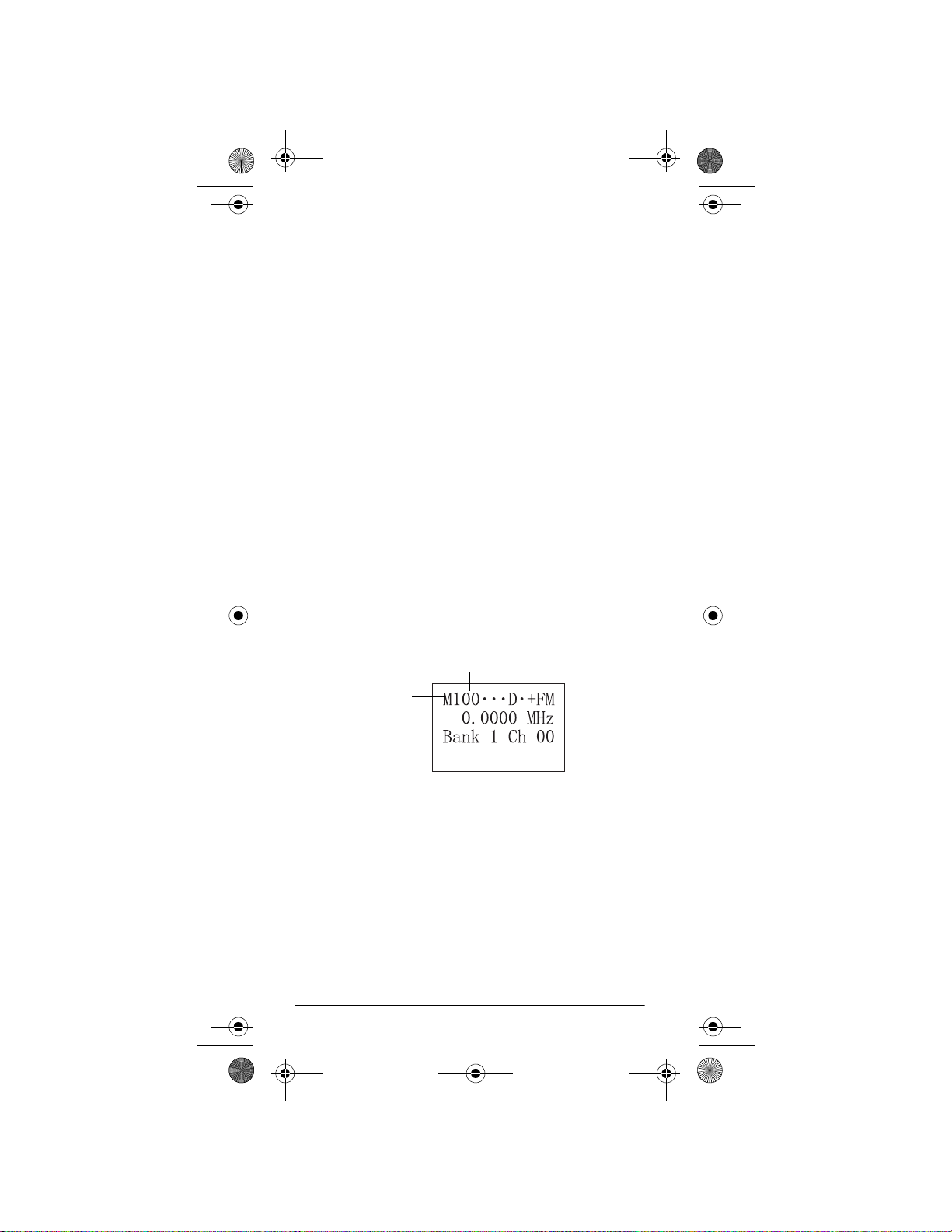
again. M and the channel number appears at the
upper left corner of the display (for example: M100).
Bank (1)
Manual
Channel (00)
2. Press
3. Use the number keys and
PGM
. M changes to P.
to enter the frequency
(including the decimal point) you want to store.
If you make a mistake, hold down
•
CL
for about 1
second to delete a single digit and about 2 seconds
to delete all digits.
ENTER
4. Press
to store the frequency into the chan-
nel. The blinking cursor disappears.
30
Operation
Page 31

20-522b.fm Page 31 Thursday, September 7, 2000 9:41 AM
Notes:
• If you made a mistake in Step 3,
Freq
briefly appears and the scanner beeps
when you press
ENTER
. Start again from Step 3.
• Your scanner automatically rounds the entered
frequency to the nearest valid frequency. For
example, if you enter a frequency of 151.473,
your scanner accepts it as 151.470.
Invalid
•Press
FUNC
then
DELAY/1
to turn the delay function on or off. To have the scanner pause for 2
seconds on this channel after a transmission
before proceeding to the next active transmission, see “Using the Delay Fu nction” on Page 40.
The scanner stores this setting in the channel.
• If you are storing frequencies for an EDACS system, you must store them in logical channel number order, with the first frequency in channel 1 for
the current bank.
FUNC
MODE
to change the receiving
P/L
then
DPL
or
STEP
, enter the PL or
(to move up through
STEP
(to move down
5. If necessary, press
mode. If you select
DPL code by pressing
the codes) or
through the codes).
6. If desired, program a text tag for the channel (see
“Assignin g a Text Tag to a Channel”).
7. The next channel in sequence is ready for programming. Press
PGM
and then repeat Steps 3 through
5.
STORING TEXT TAGS
You can custom iz e your sc an ne r by st o rin g t ex t tag s ( up
to 12 characters) for easy identification of channel transmissions, trunk IDs, or banks.
Assigning a Text Tag to a Channel
1. Press
MANUAL
, enter the channel number where
you want to enter the text, then press
again. M and the channel number appear at the
upper left corner of the displ ay (for ex ample:
Operation
MANUAL
M100
31
).
Page 32

20-522b.fm Page 32 Thursday, September 7, 2000 9:41 AM
2. Press
3. Press
PGM
. M changes to P.
TEXT
. The cursor appears at the 3rd line.
4. Enter the text using the numeral keys (see “Text
Input Chart” on Page33).
Note:
If you make a mistake, press or to move
to the character you want to change.
For example input “HAM 6m” as follows:
• “H” is the second letter associated with 4 on the
keypad. Press 4 then 2.
• “A” is the first letter associated with 2 on the key-
2
pad. Press
then 1.
• “M” is the first letter associated with 6 on the key-
pad. Press 6 then 1.
• “Space.” Press
.
•
• “6” is the s ixth number a ssociated wi th 1 on the
keypad. Press 1 then 6.
• “m” is the first letter associated with 6 on the key-
pad. Press 6 and
then press
FUNC
(for the lo wer case set) ,
1
.
ENTER
5. Press
to input the text.
Assigning a Text Tag to a Bank
1. Press
2. Select a channel within the desired bank by press-
3. Press
32
PGM
.
MANUAL
ing
bank 0 or 200 for bank 2, for example). Press
UAL
again, then press
and entering the bank number (000 for
PGM
.
FUNC
then 6. The cursor appears at the 3rd
MAN-
line of the display. Enter the text using the keypad
and press
ENTER
.
Operation
Page 33

20-522b.fm Page 33 Thursday, September 7, 2000 9:41 AM
Note:
If the channel is programmed for P/L, DPL, LTR,
MOT or ED mode, the scanner displays the mode information on the 4th line.
Text Input Chart
Notes:
FUNC
• To access t he num bers, after y ou pres s
1
, then press the desired number you want to
press
enter.
• To enter a lowercase character or a character from
the second set for key
0
, press
FUNC
after press ing
the first numeral key.
Press To Enter a Character from this Group
and 6,
1
2
FUNC 2
3
FUNC 3
4
FUNC 4
5
FUNC 5
6
FUNC 6
7
FUNC 7
8
FUNC 8
1 2 3 4 5 6 7 8 9 0
A B C
a b c
D E F
d e f
G H I
g h i
J K L
j k l
M N O
m n o
P Q R S
p q r s
T U V
t u v
Operation
33
Page 34

20-522b.fm Page 34 Thursday, September 7, 2000 9:41 AM
Press To Enter a Character from this Group
9
FUNC 9
0
FUNC 0
•
CL
W X Y Z
w x y z
. - # _ @ + * & / '
$ % ! ^ ( ) ?
Space
Back Space
` ^
FINDING AND STORING ACTIVE
FREQUENCIES
You can search for transmissions within ten ranges of
frequencies, called search banks. The search bank is divided into 10 search bands. You can change the bands
with the preprogrammed search bands in the scanner
(see “Search Banks” on Page 23). You can also change
the search bank’s search ranges manually.
Notes:
• You can use the scanner’s delay feature while
searching the service bank. See “Using the Delay
Function” on Page 40.
• The scanner does not search locked-out frequencies while searching ranges.
Searching a Preprogrammed Frequency
Range
The scanner contains these preprogrammed search
ranges, stored in search bank s (0–9).
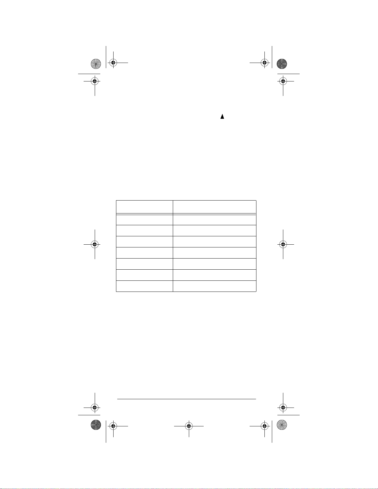
Search Bank Search Range (MHz) Description
0 460–460.625 Police
1 153.725–156.000 Police/Fire
2 462.925–463.175 Medical
34
Operation
Page 35

20-522b.fm Page 35 Thursday, September 7, 2000 9:41 AM
Search Bank Search Range (MHz) Description
3 118.000–136.00 Aircraft
4 156.250–157.425 Marine
5 866.000–868.9875 800 MHz
6 50.000–54.000 6 Meter Ham
7 144.000–148.000 2 Meter Ham
8 440.000–450.000 70 cm Ham
9 462.550–462.725 User Bank
Follow these steps to select preprogrammed search
ranges and search them for active frequencies.
1. Press
SEARCH
. The scanner searches the active
search bank.
Current
Search
Bank
Note:
To reverse a search d irection, p res s
or
2. Using the number keys, enter the search bank number for each search range you want to select or
remove.
3. When the scanner finds an active frequency, it
stops searching. To save the frequency into a channel in the channel storage bank (bank 9 only), press
FUNC
then
ENTER
Stored @ 9xx
.
appears (xx:
channel number). Press or to continue searching for additional active frequencies.
Notes:
• During search, you can manually change the band
mode or frequency step. See “Changing the
Receive Mode” on Page 45 or “Changing the Frequency Step” on Page 45.
.
Operation
35
Page 36

20-522b.fm Page 36 Thursday, September 7, 2000 9:41 AM
• If bank 9 in the channel storage banks does not
contain any empty channels,
Bank 9 full.
appears on the display’s lower line.
Storing a Frequency While Searching for a
Specified Channel
1. When the scanner stops on the frequency, press
FUNC
2. Press
a number key, then press
3. Press
4. Press
5. If desired, press
TUNE
then
MANUAL
PGM
.
FUNC
.
. Select th e specified c hannel using
then
MANUAL
TUNE
to store the frequency.
SEARCH
to resume searching.
again.
Changing a Search Range with a
Preprogrammed Range
You can replace the search range with one of the preprogrammed ranges.
1. Press
mode.
FUNC
PSR
SEARCH
then
to enter search program
and the search bank number of the cur-
rent range appear at the display’s upper left corner.
2. Press or to select the search bank you want to
replace.
3. Press
FUNC
then 5.
?SR
and the se arch bank num-
ber appear at the display’s upper left corner.
36
Operation
Page 37

20-522b.fm Page 37 Thursday, September 7, 2000 9:41 AM
Note:
After you press
FUNC
, press 5 within about 3
seconds. Otherwise, begin over at Step 1.
4. Press or to select the preprogrammed search
range.
ENTER
5. Press
press
SEARCH
to replace the search range, then
to begin searching.
Manually Changing a Search Range
mode.
FUNC
PSR
1. Press
the display’s upper left corner.
2. Press or to select the search bank number.
3. Use the number keys to enter the lower range you
want to search and store, then press
the frequency.
4. Use the number keys to enter the higher range you
want to search and store, then press
to store the frequency.
Notes:
• If you enter a higher frequency first then enter a
lower frequency, the scanner automatically
exchanges the frequencies on the display. It displays the lower frequency first and the higher frequency second.
SEARCH
then
to enter search program
and a search bank number appear at
ENTER
to store
ENTER
again
• You cannot span across frequency bands. When
manually setting search ranges, if you enter frequencies on different bands, the scanner does
not accept the entry.
5. To assign a new name to the search range, press
TEXT
twice then enter the name. If you want to edit
existing text, repeatedly press or to move the
cursor across the text. Enter the appropriate text
and press
ENTER,
then press
SEARCH
to resume
searching.
SCANNING THE CHANNELS
To begin scanning channels or to start scanning again
SCAN
after monitoring a specific channel, press
Operation
.
37
Page 38

20-522b.fm Page 38 Thursday, September 7, 2000 9:41 AM
Note:
You must store frequencies into channels before
the scanner can scan them. The scanner does not scan
empty channels.
The scanner scans through all channels (except those
you have locked out) in the active banks (see “Turning
Channel-Storage Banks Off and On” and “Locking Out
Channels or Frequencies” on Page 41).
Turning Channel-Storage Banks Off and
On
To turn off banks while scanning, press the bank’s number key until the bank’s number disappears. The scanner does not scan any of the channels within the banks
you have turned off.
Notes:
• You cannot turn o f f a ll banks. There must be at l eas t
one active bank.
• You can manually select any channel in a bank,
even if the bank is turned off.
To turn on banks while scanning, press the number key
until the bank’s number appears.
MANUALLY TUNING A FREQUENCY
1. Press
2. Use the number keys to enter the frequency.
3. Press
4. Press to move up one tuning step. Press to
When the scanner stop s on a freq uency while se archin g,
press
38
TUNE
.
ENTER
.
move down one tuning step. To move up or down in
FUNC
1 MHz increments, press
then or for
each increment.
To save the frequency into a channel (bank 9 only),
FUNC
press
xx
(
is the channel number).
FUNC
then
then
TUNE
ENTER
.
Operation
Stored @ 9xx
.
appears
Page 39

20-522b.fm Page 39 Thursday, September 7, 2000 9:41 AM
Notes:
• You cannot change the step frequency while tuning.
• You can change the receiving mode while tuning.
DELETING FREQUENCIES FROM
CHANNELS
1. Press
2. Use the number keys to enter the channel with the
3. Press
4. Press
5. Press
6. Press CL. The frequency number changes and
MANUAL
frequency you want to delete.
MANUAL
PGM
P
.
to
FUNC
0.0000 MHz
.
again.
to enter the program mode. M changes
.
appears.
LISTENING TO THE WEATHER BAND
The FCC (Federal Communications Commission) has
allocated channels for use by the National Oceanic and
Atmospheric Administration (NOAA). Regulatory agencies in other countries have also allocated channels for
use by their weather reporting authorities.
NOAA and your local weather reporting authority broadcast your local fo rec as t a nd regional weather information
on one or more of these channels.
Listening to a Weather Channel
To hear your local forecast and regional weather infor-
WX
mation, press
weather band then stops within a few seconds on the
strongest weather broadcast.
. Your scanner scans through the
Displaying Weather Messages
The weather service precedes each weather alert with a
digitally-encoded SAME signal, then a 1050 Hz tone.
You can set the scanner so, if you are monitoring a
Operation
39
Page 40

20-522b.fm Page 40 Thursday, September 7, 2000 9:41 AM
weather channel with a digitally-encoded SAME signal
when an alert is broadcast, the scanner will decode and
display the SAME message, showing the type of alert
being broadcast (or
recognize the event code).
To set the scanner to decode and display SAME messages, press
weather channel.
appear.
To set the scanner out of the SAME standby mode,
FUNC
press
Notes:
• The scanner does not display the actual location
• Your scanner can also receive weather alert tones
then WX again.
referenced by SAME messages. It uses only the
message portion of the SAME signal.
(see “Priority” on Page 43).
Unknown Message
FUNC
then WX while you listen to the
DIG WX STBY
and
DIG WX STBY
if it does not
Cancel : F+WX
disappears.
Special Features
ˆ
USING THE DELAY FUNCTION
Note:
Delay is automatically set as the default for each
channel when you turn on the scanner.
Many conversations might have a pause of several sec-
onds between a query and a reply. To avoid missing a
reply, you can program a 2-second delay into any of
your scanner’s channels. Then, when the scanner stops
D
on the chan n el ,
monitor the channel for 2 seconds after the transmission
stops before it resumes scanning or searching.
To turn delay on or off, p ress
40
appears and the scanner continues to
FUNC
Special Features
then
DELAY
.
Page 41

20-522b.fm Page 41 Thursday, September 7, 2000 9:41 AM
LOCKING OUT CHANNELS OR
FREQUENCIES
You can scan existing channels or search frequencies
faster by locking out channels or frequencies that have a
continuous transmission, such as a weather channel.
Locking Out Channels
To lock out a channel while scanning, press
the scanner stops on the channel. To lock out a channel
manually, select the channel then press
appears.
Notes:
• You can still manually select locked-out channels.
• If you lock out a channel that is set to a Motorola
trunking mode while using the subaudible decoding
mode, you can remove the lockout by removing
then reapplying power to the scanner. This makes it
easy to temporarily lock out trunking data channels.
To remove the lockout from a channel, manually select
L/OUT
the channel and press
until L disappears.
L/OUT
L/OUT
when
until
Reviewing the Lock-Out Channels
To review all channels that are locked out, press
AL
, then repeatedly press
locked-out channel. When you finish reviewing lockedout channels, press
FUNC
MANUAL
.
then
L/OUT
MANU-
to view each
Locking Out Frequencies
L
To lock out a frequency during a search, press
when the scanner stops on the frequency. The scanner
locks out the frequency, then continues searching.
Notes:
• The scanner does not store locked out frequencies
during a sea rch.
Special Features
L/OUT
41
Page 42
20-522b.fm Page 42 Thursday, September 7, 2000 9:41 AM
• You can lock out as ma ny a s 50 f requ enc ie s in each
bank. If you try to lock out more,
appears.
• If you lock out all frequencies in one search bank
and only this search bank is activated,
up...
the scanner does not search.
All ranges locked out!
Memory full!
Search
appears and
Reviewing Locked-Out Frequencies
Follow these steps to review the frequencies within a
search bank that you locked out.
1. Press
2. Press
3. Press
SEARCH
FUNC
appears. If the search bank has no locked-out frequencies,
FUNC
begin the search for locked out channels within that
bank.
Each time you press , the
scanner displays all lockedout frequencies within a
bank.
to start search.
L/OUT
then
L/O list is empty.
then to select a search bank and
. The locked-out frequency
appears.
Locked-out
Clearing a Locked-Out
Frequency
To clear a locked-out frequency, select that frequency in
order to use the locked-out frequencies review function,
then press CL.
The frequency is unlocked and
about 2 seconds. Then the next locked-out frequency
appears. If all locked out frequencies are cleared within
a bank,
L/O list is empty.
Unlocked
appears.
appears for
Clearing All Lock Out Frequencies in a
Search Bank
1. Press
2. Turn on only one search bank, the one in which you
42
SEARCH
want to clear all locked-out frequencies.
.
Special Features
Page 43

20-522b.fm Page 43 Thursday, September 7, 2000 9:41 AM
3. Turn
4. Press
SQUELCH
cator points to
FUNC
fully counterclockwise until the indi-
MIN
.
then 4.
Confirm list clear?
1=YES Press other key for NO.
appears. Press 1 to clear all lock-out frequencies
List cleared
and
Press any key other than
Note:
You cannot clear all lock-out frequencies if all
appears for about 2 seconds.
1
, to cancel clear.
frequencies in the selected bank are locked out.
5. Turn
SQUELCH
clockwise and leave it set to a point
just until the hissing sound stops.
PRIORITY
With the priority feature, you can scan through programmed channels and still not miss an important or interesting call on a specific channel. When a channel is
selected as the priority channel and priority is turned on,
the scanner checks that channel every 2 seconds, and
stays on the channel if there is activity until the activity
stops.
The scanner is preset to select Channel 00 in Bank 8 as
the priority channel. You can program a different channel as the priority channel. Also, you can program a
weather channel as the priority channel.
Notes:
• The priority feature doe s not ope rate whil e the sca n-
ner receives trunking frequencies.
• If you program a weather channel as the priority
channel, the scanner stays in the priority channel
only when the scanner detects the weather alert
tone.
Follow these steps to program a channel as the priority
channel.
1. Press
MANUAL
.
2. Use the number keys to enter the channel number
you want to program as the priority channel. Then
MANUAL
press
again.
Special Features
43
Page 44

20-522b.fm Page 44 Thursday, September 7, 2000 9:41 AM
3. Press
FUNC
then
PRI
Pri
.
appears to the right of
the frequency.
Note:
This scanner cannot set a channel as the priority
channel if the channel’s receive mode is
ED
.
LTR, MOT
, or
Follow these steps to program a weather channel as the
priority channel.
WX
1. Press
.
2. Select the weather channel you want to program as
the priority channel.
3. Press
FUNC
then
PRI
Pri
.
appears to the right of
the frequency.
PRI
To turn on the priority feature, press
Priority ON
Priority WX
(or
while scanning.
if you set the priority
to a weather channel ) ap pea rs for a bou t 3 seconds, then
P
appears. The scanner checks the priority channel every 2 seconds. It stays on the channel if there is activity
(or if it detects a wea the r al ert ton e i n Pri ori ty WX m od e),
Pri
appears and S or M changes to P.
Notes:
• Priority WX is only for receiving a weather alert.
• When the scanner detects a 1050 Hz tone, Priority
WX activates and you receive a weather alert.
PRI
To turn off the priority feature, press
OFF
appears and P disappears.
Notes:
Priority
.
• If you program a weather frequency into the priority
channel and the scanner detects a weather alert
tone on that frequen cy, the sc ann er s oun ds the al ert
tone.
44
Special Features
Page 45

20-522b.fm Page 45 Thursday, September 7, 2000 9:41 AM
• The scanner always monitors the priority channel
even if it is in a bank that is set to closed mode (see
“Changing the Open/Closed Mode” on Page 58).
CHANGING THE RECEIVE MODE
The scanner is preset to the most comm on AM or FM receive mode for each frequency range. The preset mode
is correct in m ost cases. Ho wever, some am ateur radio
transmissions and tru nke d s y ste ms do no t op era t e i n th e
preset mode. If you try to list en to a transmis sion when
the scanner is not set to the correct receive mode, the
transmission might sound weak or distorted.
If you want to listen to private line or trunking transmissions in closed mode, you might have to change the receive mode.
To change the receive mode, repeatedly press
MODE
The receive mode changes as follows:
Display Description
AM
FM
PL
DL
LT
MO
ED
AM Mode
FM Mode
FM Mode, Private Line (with
67.0–254.1 Hz PL code)
FM Mode, Digital Private Line
(with 3-digit DPL code)
FM Mode, LTR Trunking Sys-
tem (with 6-digit ID code)
FM Mode, Motorola Trunking
System (with a 4- or 5-digit ID
code)
FM Mode, EDACS Trunking
System (with 4-digit ID code)
CHANGING THE FREQUENCY STEP
The scanner searches at a preset frequency step for
each frequency range. Press
increment when moving between frequencies of a
STEP
to change the step
.
Special Features
45
Page 46
20-522b.fm Page 46 Thursday, September 7, 2000 9:41 AM
search band or follow these steps to change steps in a
specific bank.
1. Press
2. Press
SEARCH
FUNC
.
then repeatedly press to select a
bank.
3. Turn
4. Press
SQUELCH
cator points to
STEP
continuously until yo u reach the desired
fully counterclockwise until the indi-
MIN
.
step.
5. Turn
SQUELCH
clockwise and leave it set to a point
just after the hissing sound stops.
These are the change abl e freq uen cy ste ps you r sc ann er
uses for each frequency range.
Range (MHz) Search Step (kHz)
29.000-54.000 5, 10, 15, 20, 25, 30, 50, 100
108.000-136.9875 12.5, 25, 50, 100
137.000-174.000 5, 10, 15, 20, 25, 30, 50, 100
380.000-512.000 12.5, 25, 50, 100
806.000-823.9875 12.5, 25, 50, 100
849.000-868.9875 12.5, 25, 50, 100
894.000-960.000 12.5, 25, 50, 100
USING THE ATTENUATOR
To reduce interference or noise caused by strong signals, you can reduce the scanner’s sensitivity to these
signals. Pr ess
ner’s sensitivity on the current channel.
Note:
If you turn on this feature, the scanner might not
receive weak signals.
To turn off the attenuator, press
pears.
This setting is stored for each channel.
46
ATT
until A appears to reduce the scan-
ATT
again. A disap-
Special Features
Page 47

20-522b.fm Page 47 Thursday, September 7, 2000 9:41 AM
USING THE DISPLAY BACKLIGHT
You can turn on the display’s backlight for easy viewing
LIT
in dimly lit areas. Press
5 seconds. To turn off the light before it automatically
turns off, press
LIT
again.
to turn on the display light for
TURNING THE KEY TONE ON AND OFF
Each time you press any of the scanner’s keys, the
scanner sounds a tone. Follow these steps to turn the
scanner’s key tone off or on.
1. If the scanner is on, turn
clockwise until it clicks to turn the scanner off.
2. Turn
3. While
VOLUME OFF/MAX
ner on .
ing
Welcome To Multi-System Trunk-
appears.
Welcome To Multi-System Trunk-
ing
appears, press 1 to turn on the key tone or 2 to
turn it off.
VOLUME OFF/MAX
clockwise to turn the scan-
counter-
USING THE KEYLOCK
Once you program your scanner, you can protect it from
accidental program changes by turning on the keylock
feature. When the keypad is locked, the only controls
that operate are
UME
.
Note:
You cannot activate the keylock when in the mid-
dle of programming.
To turn on the ke yl oc k, pre ss
board
Locked
board Locked
locking the keypad.
To turn off the keylock, press
scanner beeps once and
pears about 1 second.
FUNC
appears for about 1 second.
appears when you pr ess a ny ke y after
/LIT, SQUELCH
,
FUNC
then /
FUNC
then /
, and
Keyboard Unlocked
LIT
.
LIT
VOL-
KeyKey-
. The
ap-
CHANGING THE DISPLAY CONTRAST
1. Press
MANUAL
.
Special Features
47
Page 48

20-522b.fm Page 48 Thursday, September 7, 2000 9:41 AM
2. Press
FUNC
then 9.
contrast.
3. Press or to select the contrast.
4. Press
ENTER
Use Up/Down keys to set
appears.
to set the display contrast.
CLONING THE PROGRAMMED DATA
FROM SCANNER TO SCANNER
You can transfer the programmed data to and from another Radio Shack Cat. No. 20-522A or Cat. No. 20 -196
scanner using the supplied clone cable. To clone the data, follow these steps.
1. Turn on both scanners.
2. Connect the supplied clone cable to each scanner’s
PC/IF
cable
3. Press .
other
4. Press 1 to send the data to the other unit or press
any other key to cancel the operation.
The scanner sends the data. To exit the clone mode, remove the cable .
CLONE MODE UP to send, remove
jack.
exit
to
appears.
Confirm send data? 1=Yes Press
key for No.
appears.
Trunking Operation
ˆ
The scanner tracks transmissions that use the Motorola
Type I and Type II (such as Smartnet and Privacy Plus)
and hybrid analog trunking systems, plus GE/Ericsson
(EDACS) and EF Johnson (LTR) type systems, which
are extensively used in many communication systems.
Trunking systems alloc ate a f ew fre quenc ies to m any d ifferent users. When the mobile unit transmits a signal,
one frequency is chosen from among the allocated frequencies in that trunking system. The user’s
group
is sent with the signal.
To receive trunking signals, you must store all the trunking group frequencies in one bank (see “Storing Known
Frequencies into Channels” on Page 30) and input ID
48
Trunking Operation
ID talk
®
Page 49

20-522b.fm Page 49 Thursday, September 7, 2000 9:41 AM
codes in the ID memory (see “Storing Talk Group IDs”
on Page 55). To listen to the transmission, the mode of
the programmed channel must be the same as that of
the trunking channel (LT, MO, or ED).
When an ID code is received, the ID list for the bank is
searched, and if found, the text name stored for the ID
appears. If not found, scanning resumes immediately
unless the bank is in open trunking mode.
Note:
There might be more than one talk g rou p transmitting at a time in some Motorola trunking systems. If you
set the scanner to manually tune in Motorola trunking
mode, you will hear the talk group on that channel, but
the display will alternate between all active IDs.
Trunking group frequencies are included in the supplied
Police Call Trunking Guide
talk group information is also widely available on the Internet, at
www.trunkscanner.com
. Frequency fleet map and
for example.
UNDERSTANDING TRUNKING
In the past, groups that transmit frequently, such as police departments, could transmit on only a few frequencies. This resulted in heavy traffic and often required 2way radio users to wait for a specific frequency to clear
before transmitting. Trunked systems allow more groups
of 2-way radio users to use few er freque ncies . Instea d of
selecting a specific frequency to transmit on, a trunked
system chooses one of several frequencies when the 2way radio user transmits. The system automatically
transmits the call on that frequency, and also sends a
code that ide ntifi es that 2- way radi o user’ s transmi ssion
on a control channel.
This scanner lets you easily hear both the call and response transmissions for that 2-way radio user and
therefore follow the conversation. For EDACS and Motorola (above 806 MHz range), the scanner monitors the
control channel between each transmission to identify talk
groups. For some Motorola (under 512 MHz range) and
LTR systems, the scanner uses the subaudible data sent
with each transmission to identify talk groups.
Trunking Operation
49
Page 50

20-522b.fm Page 50 Thursday, September 7, 2000 9:41 AM
SETTING SQUELCH FOR THE
T RUNKING MODE
Your scanner automatic all y m utes the aud io du rin g trun k
scanning when it decodes control channel data. However, we recommend you turn
leave it set to a point just after the hissing sound stops.
This lets the scanner quickly acquire the data channel.
SQUELCH
clockwise and
PROGRAMMING TRUNKING
FREQUENCIES
You program trunking frequencies just like non-trunked
frequencies, except that you must store the appropriate
mode (MO, ED, or LT) with each frequency.
Notes:
• You can store only one trunked EDACs and Motor-
ola channel in a bank. You can, however, mix LTR
and conventional channels in a bank.
• If you are scanning UHF trunking frequencies under
the 512 MHz range using subaudible data and are
not using a base frequency and offset, lock out all
data channels. See “Programming Motorola Trunking Systems (UHF-Lo)” on Page 51 and “Locking
Out Channels or Frequencies” on Page 41. Turn off
the scanner to remove the lockouts.
• If you are programming trunked frequencies for
Motorola Type I and hybrid systems, you must first
program the fleet map (see “Programming Fleet
Maps” on Page 53).
• You must store frequencies using the subaudible
trunking method in banks, mode by mode.
Follow these steps to program trunked frequencies.
PGM
1. Press
to enter the ID program mode.
2. Repeatedly press
Johnson,
(GE/Ericsson) system to scan. This sets the talk
group ID decoding method to be used for the bank.
50
and select the bank, then press
MODE
to select LT for EF
MO
for Motorola, or ED for the EDACS
Trunking Operation
TRUNK
Page 51

20-522b.fm Page 51 Thursday, September 7, 2000 9:41 AM
Notes:
--
• If you select
scanner does not scan trunked frequencies.
Instead, y ou see:
• If you programmed a Motorola Type I or Hybrid
system, see “Programming Fleet Maps” on
Page 53.
PGM
3. Press
4. Store the trunking frequencies into subsequent
channels in the same bank (see “Storing Known
Frequencies into Channels” on Page 30).
5. Repeatedly pres s
LT
—
the EDACS (GE/Ericsson) system.
6. Press
the ID mode,
frequenci es.
to enter the program mode.
for EF Johnson, MO for Motorola, or ED for
SCAN
. If the scanner’s recei ve mod e m atches
instead of LT, MO, or ED, the
MODE
to select the trunking mode
T
appears and the scanner scans the
Programming Motorola Trunking Systems
(UHF-Lo)
You can program the scanner to receive transmissions
in the UHF-Lo band (380–512 MHz) of the Motorola
trunking system. You can receive these transmissions
by:
• Checking the trunking system’s control channel.
You must program th e sy s tem ’ s bas e fre quency and
offset frequency to do this.
• Decoding the subaudible data transmitted with the
signals. When you do this, the scanner might detect
wrong IDs but you can easily receive trunking frequencies without programming the base and offset
frequenci es.
Trunking Operation
51
Page 52

20-522b.fm Page 52 Thursday, September 7, 2000 9:41 AM
Notes:
• Base and offset frequencies vary for each type of
trunking system. You can get information about
these frequencies for the trunking system you want
to scan using
www.trunkscanner.com
, other In ter -
ne t s o u r ces , o r l o c a l l y -published guidebooks.
• The scanner automatic ally decode s suba udibl e data
it receives in the VHF band.
• If you try to enter an of fset fre quenc y in th e VHF and
UHF-Hi bands (137–174 and 806–960 MHz), the
scanner will ignore the entry.
Follow these steps to program Motorola trunking frequencies in the UHF-Lo band.
PGM
1. Select the bank, then press
to enter the pro-
gram mode.
2. Store the base frequency into channel 00 of the
bank you selected, then store the trunking frequencies into subsequent channels in the same bank.
3. Press
MO
(Motorola).
4. Press
TRUNK
then repeatedly press
FUNC
then 9.
12.5 kHz
MODE
to select
(the default offset
frequency) appears.
Offset Frequency
5. Repeatedly press
frequency you want (
kHz
).
Note:
Offset frequencies above 50 kHz do not
FUNC
then 9 to select the offset
12.5 kHz, 25.0 kHz
, or
appear and are used only for subaudible decoding
mode.
6. Program the trunking frequencies (see “Programming Trunking Frequencies” on Page 50).
52
Trunking Operation
50
Page 53
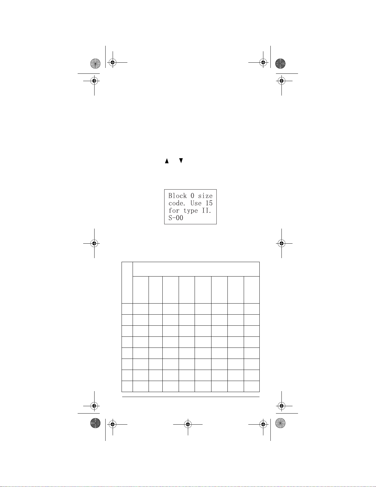
20-522b.fm Page 53 Thursday, September 7, 2000 9:41 AM
PROGRAMMING FLEET MAPS
You must set the fleet map if you want to receive a Motorola Type I system. Fleet maps are included along with
other information about Motorola Type I systems at
www.trunkscanner.com
Follow these steps to program a fleet map.
.
1. Press
PGM
then
TRUNK
.
2. For each bank you want to program, repeatedly
FUNC
press
3. Press
4. Press
, , or to select the bank.
FUNC
.
8
. The following display appears:
5. Enter the size code supplied with the Type I system
information, referring to the instruction that appears
on the display. If the information was not supplied,
try the following common fleet maps.
B
Size Code
L
O
C
123 4 5 6 7 8
K
0 S11 S4 S4 S12 S4 S3 S10 S1
1 S11 S4 S4 — S4 S10 S10 S1
2 S11 S4 S4 S4 S12 S4 S11 S2
3 S11 S4 S4 S4 — S4 S4 S2
4 S11 S4 S4 S4 S4 S12 S4 S3
5 S11 S4 S4 S4 S4 — S4 S3
6 S11 S4 S12 S4 S4 S12 S4 S4
7 S11 S4 — S4 S4 — S4 S4
Trunking Operation
53
Page 54

20-522b.fm Page 54 Thursday, September 7, 2000 9:41 AM
B
Size Code
L
9 10111213141516
O
C
K
0S4S0S4S0S3S4S4S3
1S4S0S0S0S3S3S4S10
2S0S0S0S0S11S10S4S10
3S0S0S0S0S4S4S11S11
4S0S0S0S0S4S4S11S0
5S0S0S0S0S0S4S0S0
6S0S4S0S0S0S12S12S12
7S0S4S0S4S0— — —
6. Press
ENTER
for each entry. If you make a mistake,
CL
press
Note:
and enter the correct size code.
The default setting of the bank is for Motorola
Type II. However, if you set Type I and you want to
return to Type II, enter 15 at Step 5.
7. To confirm the input, repeat Steps 1–5 and press
ENTER
. Each time you press
the size code. If you find an error, press
ENTER
, you confirm
CL
and
begin again at Step 1.
SCAN
8. Press
to start scanning.
TALK GROUP IDS
You can program up to 100 talk group IDs in each bank.
When the scanner stops on a transmission in the LTR,
Motorola, or EDACS mode, it checks to see if the ID has
been stored. In the closed mode, the scanner only stops
on the transmission and displays its text tag if you have
stored and not locked out the ID. In the open mode, the
scanner always stops on a transmission, but it displays
the ID’s text tag if you have stored the ID.
54
Trunking Operation
Page 55

20-522b.fm Page 55 Thursday, September 7, 2000 9:41 AM
Storing Talk Group IDs
To store a talk group ID when scanning, press
TRUNK
when the scanner stops on a transmission. The bottom
line changes to
ID#XXXX
, indicating that the ID is
stored.
Note:
When you try to store more than 100 talk group
IDs in a bank,
Memory full!
appears. Clear some
talk group IDs in order to store new ones (see “Clearing
Talk Group IDs” on Page56).
Follow these steps to manually store talk group IDs or to
edit a stored ID.
PGM
1. Press
2. Press
.
TRUNK
.
3. To select the bank where you want to store the ID,
FUNC
press
4. Press
5. Enter the talk group ID and press
then or .
MODE
to select LT, MO, or ED.
ENTER
. If neces-
sary, use the decimal point for a hyphen.
Note:
If you made a mistake in Step 4,
ID
. appears and the scanner beeps when you
ENTER
press
6. Press
press
. Start again at Step 3.
TEXT
and enter the text tag for the ID, then
ENTER
.
Invalid
7. To store the next ID memory in sequence, press
and repeat Steps 4 and 5 to enter more IDs.
8. Press
SCAN
to start scanning.
Talk Group ID Hold
You can set your scanner to follow a trunking signal that
.
TRUNK
for
55
you want to track durin g sc an nin g.
more than 2 seconds.
To release ID hold, press
ID hold ON.
SCAN
or
Trunking Operation
Hold down
appears.
TRUNK
Page 56

20-522b.fm Page 56 Thursday, September 7, 2000 9:41 AM
Locking Out Talk Group IDs
Note:
You can only lock out talk group IDs when the
scanner is in the closed mode (see “Open and Closed
Modes” on Page 57).
PGM
1. Press
2. Press
3. Press
.
TRUNK
FUNC,
.
or to move the desired bank.
4. Press or to select the ID memory.
L/OUT
5. Press
to lock out the ID. L appears.
6. To remove the lockout from a trunking ID, manually
select the ID memory, and press
L/OUT
until L dis-
appears.
Reviewing Locked-Out Talk Group IDs
Note:
You cannot clear all lockouts from a talk group at
the same time.
1. Press
2. Press
PGM
FUNC
then
then
TRUNK
.
L/OUT
. The locked out ID app ears .
If the ID memory bank has no locked out ID, you
hear the low beep tone.
3. Press
Or, just press
FUNC
or
then
or
to select a search b ank.
to search for any locked
out IDs in a bank.
Clearing Talk Group IDs
1. Press
2. Press
3. Press
PGM
FUNC
FUNC
TRUNK
then
.
, or to select ID memory.
then CL.
Clearing All Talk Group IDs in One Bank
You can clear all talk group IDs within a bank. This lets
you quickly delete all talk group IDs from a bank (for example, if you want to us e t he b an k t o s tore a d ifferent set
of talk group IDs).
56
Trunking Operation
Page 57

20-522b.fm Page 57 Thursday, September 7, 2000 9:41 AM
1. Press
2. Press
PGM
TRUNK
.
to enter a talk group ID memory
mode.
FUNC
3. Select a talk group ID bank using
FUNC
4. Press
?1=YES
5. Press
Please Wait
Note:
To cancel the deletion, press any key except
then 3.
Press other key for NO.
1
to clear the all talk group IDs within a bank.
then
Confirm list clear
List Cleared
, or .
appears.
appears.
The scanner returns to the talk group ID memory mode.
OPEN AND CLOSED MODES
When set to the open mode, the scanner only uses the
ID list to look up ID text tags and stops on any ID code.
When set to the closed mode, the scanner stops only on
signals that have an ID code which is found in the ID list
for the bank.
Note:
When you select a channel manually, any trans-
mission opens squelch, regardless of the current mode.
Closed Mode
1
.
The open or closed mode is set in each channel storage
+
bank.
or – appears under the channel storage bank’s
number while scanning. Or, the status display shows the
OPEN/CLOSED mode at the top line while the scanner
is in manual mode or receiving a signal during scanning.
Trunking Operation
57
Page 58

20-522b.fm Page 58 Thursday, September 7, 2000 9:41 AM
When no ID code is programmed into the scanner, it receives the signal in PL, DPL, LTR, MOT, or ED mode.
Mode Open Closed
PL
and
DPL
MOT/
ED/
LTR
Accepts any PL and
DPL.
Stops on any transmission. If the ID i s stored ,
displays the text tag.
Otherwise, displays
the talk group ID.
Accepts only the PL
or DPL stored in the
channel.
Only stops on a
transmission if the
ID is stored. Displays the text tag.
Changing the Open/Closed Mode
1. Press
2. Press
3. Press
4. Repeat Steps 2–3 for each bank.
ˆ
MANUAL
FUNC
storage bank.
CLOSED
the 10th digit on the top line of the display changes
from + to – or vice versa.
.
then or to select the channel
FUNC
then 2.
appears. After that message disappears,
Bank OPEN
or
A General Guide to
Scanning
Bank
Reception of the frequencies covered by your scanner is
mainly “line-of-sight.” That means you usually cannot
hear stations that are beyond the horizon.
58
A General Guide to Scanning
Page 59

20-522b.fm Page 59 Thursday, September 7, 2000 9:41 AM
GUIDE T O FREQUENCIES
US Weather Frequencies
162.400 162.425 162.450 162.475
162.500 162.525 162.550
Ham Radio Frequencies
Ham radio operators often transmit emergency information when other means of communication break down.
The chart below shows the frequencies the scanner receives that ham radio operators normally use:
Wavelength Frequencies (MHz)
10-Meter 29.000–29.700
6-Meter 50.000–54.000
2-Meter 144.000–148.000
70-cm 420.000–450.000
33-cm 902.000–928.000
Birdie Frequencies
Every scanner has birdie frequencies. Birdies are signals created inside the scanner’s receiver. These operating frequencies might interfere with transmissions on
the same frequencies. If you program one of these frequencies, you hear only noise on that frequency. If the
interference is not severe, you might be able to turn
SQUELCH
This scanner’s birdie frequencies (in MHz) are:
29.0000 147.7650 415.3375 475.2375
31.9500 150.1500 419.3375 479.2375
32.1000 151.7600 423.3250 483.2250
35.9400 155.7500 427.3125 487.2250
38.4000 159.7450 429.0500 491.2125
clockwise to cut out the birdie.
A General Guide to Scanning
59
Page 60
20-522b.fm Page 60 Thursday, September 7, 2000 9:41 AM
42.9750 163.7400 431.3125 495.2125
43.9300 167.7300 435.3000 499.2000
47.9250 171.5500 439.3000 503.2000
49.9200 383.3875 443.2875 507.1875
51.9150 387.3750 447.2875 511.1875
54.0000 391.3750 451.2750 814.7000
108.0000 395.3750 455.2750 818.0125
115.8125 399.3625 459.2625 820.1125
123.8000 403.3625 463.2625 823.2625
131.7875 407.3500 467.2500 944.0500
139.7750 411.3500 471.2500 960.0000
143.7700
To find the birdies in your scanner, begin by disconnecting the antenna and moving it away from the scanner.
Make sure that no other nearby radio or TV sets are
turned on near the scanner. Use the search function and
scan every frequency range from its lowest frequency to
the highest. Occasionally, the searching will stop as if it
had found a signal, often without any sound. This is a
birdie. Make a list of al l the bird ies in you r scanner for future reference.
60
A General Guide to Scanning
Page 61

20-522b.fm Page 61 Thursday, September 7, 2000 9:41 AM
GUIDE TO THE ACTION BANDS
Typical Band Usage
VHF Band
Low Range 29.00–50.00 MHz
6-Meter Amateur 50.00–54.00 MHz
U.S. Government 137.00–144.00 MHz
2-Meter Amateur 144.000–148.00 MHz
High Range 148.00–174.00 MHz
UHF Band
Military Aircraft 380.00–384.00 MHz
U.S. Government 406.00–420.00 MHz
70-cm Amateur 420.00–450.00 MHz
Low Range 450.00–470.00 MHz
FM-TV Audio Broadcast, Wide
Band
800 Band Law Enforcement 806.00–824.00 MHz
Conventional Systems 851.00–856.00 MHz
Conventional/Trunked Systems 85 6.00–861.00MHz
Public Safety 866.00–869.00 MHz
Trunked Private/General 894.00–960.00 MHz
Primary Usage
470.000–512.00 MHz
As a general rule, most of th e radio acti vit y is conc entrated on the following frequencies:
VHF Band
Activities Frequencies
Government, Police, and Fire 153.785–155.980 MHz
Emergency Services 158.730–159.460 MHz
Railroad 160.000–161.900 MHz
UHF Band
Activities Frequencies
Land-Mobile “Paired” Frequencies 450.000–470.000 MHz
Base Stations 451.025–454.950 MHz
Mobile Units 456.025–459.950 MHz
Repeater Units 460.025–464.975 MHz
Control Stations 465.025–469.975 MHz
A General Guide to Scanning
61
Page 62

20-522b.fm Page 62 Thursday, September 7, 2000 9:41 AM
Note:
Remote control stations and mobile units operate
at 5 MHz higher than their associated base stations and
relay repeater units.
BAND ALLOCATION
To help decide which frequency ranges to scan, use the
following listing of the typical services that use the frequencies your scanner receives. These frequencies are
subject to change, and might vary from area to area. For
a more complete listing, refer to
including Fire and Emergency Services
your local RadioShack store.
Abbreviations Services
AIR . . . . . . . . . . . . . . . . . . . . . . . . . . . . . . . . . . . . . . . . Aircr a ft
BIFC . . . . . . . . . . . . . . . . . . Boise (ID) Interagency Fire Cache
BUS. . . . . . . . . . . . . . . . . . . . . . . . . . . . . . . . . . . . . . . Business
CAP. . . . . . . . . . . . . . . . . . . . . . . . . . . . . . . . . . . Civil Air Patrol
CCA. . . . . . . . . . . . . . . . . . . . . . . . . . . . . . . . . Common Carrier
CSB. . . . . . . . . . . . . . . . . . . . . . . . . . . . Conventional Systems
CTSB. . . . . . . . . . . . . . . . . . . . Conventional/Trunked Systems
FIRE . . . . . . . . . . . . . . . . . . . . . . . . . . . . . . . . Fire Department
HAM . . . . . . . . . . . . . . . . . . . . . . . . . . . . Amateur (Ham) Radio
GOVT . . . . . . . . . . . . . . . . . . . . . . . . . . . . Federal Government
GMR . . . . . . . . . . . . . . . . . . . . . . . . . . . . General Mobile Radio
GTR. . . . . . . . . . . . . . . . . . . . . . . . . . . . . . . . . General Trunked
IND . . . . . . . . . . . . . . . . . . . . . . . . . . . . . . . Industrial Services
(Manufacturing, Construction, Farming and Forest Products)
MAR . . . . . . . . . . . . . . . . . . . . . . . . . . . Military Amateur Radio
MARI . . . . . . . . . . . . . . . . . . . . . . . . . . . Maritime Limited Coast
MARS . . . . . . . . . . . . . . . . . . . . .Military Affiliate Radio System
MED . . . . . . . . . . . . . . . . . . . . . . Emergency/Medical Services
MIL . . . . . . . . . . . . . . . . . . . . . . . . . . . . . . . . . . . . . U.S. Military
MOV . . . . . . . . . . . . . . . . . . . . . . Motion Picture/Video Industry
NEW . . . . . . . . . . . . . . . . . . . . . . . . . . . . . New Mobile Narrow
NEWS . . . . . . . . . . . . . . . Relay Press (Newspaper Reporters)
OIL. . . . . . . . . . . . . . . . . . . . . . . . . . . . . .Oil/Petroleum Industry
POL. . . . . . . . . . . . . . . . . . . . . . . . . . . . . . . .Police Department
PUB. . . . . . . . . . . . . . . . . . . . . . . . . . . . . . . . . . Public Services
(Public Safety, Local Government and Forestry Conservation)
PSB. . . . . . . . . . . . . . . . . . . . . . . . . . . . . . . . . . . . Public Safety
PTR. . . . . . . . . . . . . . . . . . . . . . . . . . . . . . . . . .Private Trunked
ROAD . . . . . . . . . . . . . . . . . . . . Road & Highway Maintenance
RTV. . . . . . . . . . . . . . . . . Rad io/TV Remote Broadca st Pickup
TAXI. . . . . . . . . . . . . . . . . . . . . . . . . . . . . . . . . . . .Taxi Services
TELB . . . . . . . . . . . . . . . . . . . . . . . . . . . . . . . Mobile Telephone
TELM. . . . . . . . . . . . . . . . . . . . . . . . . . Telephone Maintenance
TOW . . . . . . . . . . . . . . . . . . . . . . . . . . . . . . . . . . . . Tow Trucks
TRAN. . . . . . . . . . . . . . . . . . . . . . . . . . Transportation Services
TSB . . . . . . . . . . . . . . . . . . . . . . . . . . . . . . . . Trunked Systems
TVn . . . . . . . . . . . . . . . . . . . . . . . . . . . FM-TV Audio Broadcast
USXX. . . . . . . . . . . . . . . . . . . . . . . . . . . Government Classified
UTIL. . . . . . . . . . . . . . . . . . . . . . . . . . . . Power & Water Utilities
Shipboard Radio and Private Stations)
(Trucks, Tow Trucks, Buses, Railroad, Other)
Police Call R adi o Gu i de
, available at
(Coast Guard, Marine Telephone,)
62
A General Guide to Scanning
Page 63

20-522b.fm Page 63 Thursday, September 7, 2000 9:41 AM
WTHR . . . . . . . . . . . . . . . . . . . . . . . . . . . . . . . . . . . . . Weather
HIGH FREQUENCY (HF)
10-Meter Amateur Band
29.000–29.700 . . . . . . . . . . . . . . . . . . . . . . . . . . . . . . . . . HAM
VERY HIGH FREQUENCY (VHF)
VHF Low Band—(29–50 MHz—in 5 kHz steps)
29.900–30.550 . . . . . . . . . . . . . . . . . . . . . . . . . . . . .GOVT, MIL
30.580–31.980 . . . . . . . . . . . . . . . . . . . . . . . . . . . . . .IND, PUB
32.000–32.990 . . . . . . . . . . . . . . . . . . . . . . . . . . . . .GOVT, MIL
33.020–33.980 . . . . . . . . . . . . . . . . . . . . . . . . . BUS, IND, PUB
34.010–34.990 . . . . . . . . . . . . . . . . . . . . . . . . . . . . .GOVT, MIL
35.020–35.980 . . . . . . . . . . . . . . . . . . . BUS, PUB, IND, TELM
36.000–36.230 . . . . . . . . . . . . . . . . . . . . . . . . . . . . .GOVT, MIL
36.250 . . . . . . . . . . . . . . . . . . . . . . . . . . . . . . . O il Spill Cleanup
36.270–36.990 . . . . . . . . . . . . . . . . . . . . . . . . . . . . .GOVT, MIL
37.020–37.980 . . . . . . . . . . . . . . . . . . . . . . . . . . . . . . PU B, IND
38.000–39.000 . . . . . . . . . . . . . . . . . . . . . . . . . . . . .GOVT, MIL
39.020–39.980 . . . . . . . . . . . . . . . . . . . . . . . . . . . . . . . . . .PUB
40.000–42.000 . . . . . . . . . . . . . . . . . . . . . . . GOVT, MIL, MARI
42.020–42.940 . . . . . . . . . . . . . . . . . . . . . . . . . . . . . . . . . .POL
42.960–43.180 . . . . . . . . . . . . . . . . . . . . . . . . . . . . . . . . . . IND
43.220–43.680 . . . . . . . . . . . . . . . . . . . . . . . .TELM , IND, PUB
43.700–44.600 . . . . . . . . . . . . . . . . . . . . . . . . . . . . . . . . .TRAN
44.620–46.580 . . . . . . . . . . . . . . . . . . . . . . . . . . . . . POL, PUB
46.600–46.990 . . . . . . . . . . . . . . . . . . . . . . . . . . . . . . . . G OVT
47.020–47.400 . . . . . . . . . . . . . . . . . . . . . . . . . . . . . . . . . .PUB
47.420 . . . . . . . . . . . . . . . . . . . . . . . . . . . .American Red Cross
47.440–49.580 . . . . . . . . . . . . . . . . . . . . . . . . . . . . . .IND, PUB
49.610–49.990 . . . . . . . . . . . . . . . . . . . . . . . . . . . . . . . . . . .MIL
6-Meter Amateur Band—(50–54 MHz)
50.000–54.000 . . . . . . . . . . . . . . . . . . . . . . . . . . . . . . . . . .HAM
Aircraft Band—(108–137 MHz)
108.00–121.490 . . . . . . . . . . . . . . . . . . . . . . . . . . . . . . . . . .AIR
121.500 . . . . . . . . . . . . . . . . . . . . . . . . . . . . . . .AIR Emergency
121.510–136.975 . . . . . . . . . . . . . . . . . . . . . . . . . . . . . . . . AIR
U.S. Government Band (137–144 MHz)
137.000–144.000 . . . . . . . . . . . . . . . . . . . . . . . . . . .GO VT, MIL
2-Meter Amateur Band (144–148 MHz)
144.000–148.000 . . . . . . . . . . . . . . . . . . . . . . . . . . . . . . . .HAM
VHF High Band (148–174 MHz)
148.050–150.345 . . . . . . . . . . . . . . . . . . . . . . . CAP, MAR, MIL
150.775–150.790 . . . . . . . . . . . . . . . . . . . . . . . . . . . . . . . .MED
150.815–150.980 . . . . . . . . . . . . . . . . . TOW, Oil Spill Cleanup
150.995–151.475 . . . . . . . . . . . . . . . . . . . . . . . . . .ROAD, POL
151.490–151.955 . . . . . . . . . . . . . . . . . . . . . . . . . . . .IND, BUS
151.985 . . . . . . . . . . . . . . . . . . . . . . . . . . . . . . . . . . . . . . .TELM
152.0075 . . . . . . . . . . . . . . . . . . . . . . . . . . . . . . . . . . . . . . .MED
A General Guide to Scanning
63
Page 64

20-522b.fm Page 64 Thursday, September 7, 2000 9:41 AM
152.030–152.240 . . . . . . . . . . . . . . . . . . . . . . . . . . . . . . . TELB
152.270–152.480 . . . . . . . . . . . . . . . . . . . . . . .IND, TAXI, BUS
152.510–152.840 . . . . . . . . . . . . . . . . . . . . . . . . . . . . . . . TELB
152.870–153.020 . . . . . . . . . . . . . . . . . . . . . . . . . . . IND, MOV
153.035–153.725 . . . . . . . . . . . . . . . . . . . . . . . .IND, OIL, UTIL
153.740–154.445 . . . . . . . . . . . . . . . . . . . . . . . . . . .PUB, FIRE
154.490–154.570 . . . . . . . . . . . . . . . . . . . . . . . . . . . .IND, BUS
154.585 . . . . . . . . . . . . . . . . . . . . . . . . . . . . . . Oil Spill Cleanup
154.600–154.625 . . . . . . . . . . . . . . . . . . . . . . . . . . . . . . . .BUS
154.655–156.240 . . . . . . . . . . . . . . . . MED, ROAD, POL, PUB
156.255–157.425 . . . . . . . . . . . . . . . . . . . . . . . . . . . OIL, MARI
157.450 . . . . . . . . . . . . . . . . . . . . . . . . . . . . . . . . . . . . . . . .MED
157.470–157.515 . . . . . . . . . . . . . . . . . . . . . . . . . . . . . . . TOW
157.530–157.725 . . . . . . . . . . . . . . . . . . . . . . . . . . . .IND, TAXI
157.740 . . . . . . . . . . . . . . . . . . . . . . . . . . . . . . . . . . . . . . . .BUS
157.770–158.100 . . . . . . . . . . . . . . . . . . . . . . . . . . . . . . . TELB
158.130–158.460 . . . . . . . . . . . . . BUS, IND, OIL, TELM, UTIL
158.490–158.700 . . . . . . . . . . . . . . . . . . . . . . . . . . . . . . . TELB
158.730–159.465 . . . . . . . . . . . . . . . . . . . . . POL, PUB, ROAD
159.480 . . . . . . . . . . . . . . . . . . . . . . . . . . . . . . . . . . . . . . . . .OIL
159.495–161.565 . . . . . . . . . . . . . . . . . . . . . . . . . . . . . . .TRAN
161.580–162.000 . . . . . . . . . . . . . . . . . . . . . . .OIL, MARI, RTV
162.0125–162.350 . . . . . . . . . . . . . . . . . . . .GOVT, MIL, USXX
162.400–162.550 . . . . . . . . . . . . . . . . . . . . . . . . . . . . . . WTHR
162.5625–162.6375 . . . . . . . . . . . . . . . . . . .GOVT , MIL, USXX
162.6625 . . . . . . . . . . . . . . . . . . . . . . . . . . . . . . . . . . . . . . .MED
162.6875–163.225 . . . . . . . . . . . . . . . . . . . .GOVT, MIL, USXX
163.250 . . . . . . . . . . . . . . . . . . . . . . . . . . . . . . . . . . . . . . . .MED
163.275–166.225 . . . . . . . . . . . . . . . . . . . . .GOVT, MIL, USXX
166.250 . . . . . . . . . . . . . . . . . . . . . . . . . . . . . GOVT, RTV, FIRE
166.275–169.400 . . . . . . . . . . . . . . . . . . . . . . . . . .GOVT, BIFC
169.445–169.505 . . . . . . . . . . . . . . . . . Wireless Mikes, GOVT
169.550–169.9875 . . . . . . . . . . . . . . . . . . . .GOVT, MIL, USXX
170.000–170.150 . . . . . . . . . . . . . . . . BIFC, GOVT, RTV, FIRE
170.175–170.225 . . . . . . . . . . . . . . . . . . . . . . . . . . . . . . GOVT
170.245–170.305 . . . . . . . . . . . . . . . . . . . . . . . Wireless Mikes
170.350–170.400 . . . . . . . . . . . . . . . . . . . . . . . . . . .GOVT, MIL
170.425–170.450 . . . . . . . . . . . . . . . . . . . . . . . . . . . . . . . BIFC
170.475 . . . . . . . . . . . . . . . . . . . . . . . . . . . . . . . . . . . . . . . .PUB
170.4875–173.175 . . . . . . . . . . . .GOV T, PUB, Wireless Mikes
173.225–173.5375 . . . . . . . . . . . . . . . MOV, NEWS, UTIL, MIL
173.5625–173.5875 . . . . . . . . . . . . MIL, Medical/Crash Crews
173.600–173.9875 . . . . . . . . . . . . . . . . . . . . . . . . . . . . . GOVT
ULTRA HIGH FREQUENCY (UHF)
U. S. Government Band (406–420 MHz)
406.125–419.975 . . . . . . . . . . . . . . . . . . . . . . . . .GOVT, USXX
70-cm Amateur Band (420–450 MHz)
420.000–450.000 . . . . . . . . . . . . . . . . . . . . . . . . . . . . . . . .HAM
Low Band (450–470 MHz)
450.050–450.925 . . . . . . . . . . . . . . . . . . . . . . . . . . . . . . . .RTV
451.025–452.025 . . . . . . . . . . . . . . . . . . IND, OIL, TELM, UTIL
452.0375–453.00 . . . . . . . . . . .IND, TAXI, TRAN TOW, NEWS
453.0125–454.000 . . . . . . . . . . . . . . . . . . . . . . . . . . .PUB, OIL
454.025–454.975 . . . . . . . . . . . . . . . . . . . . . . . . . . . . . . . TELB
455.050–455.925 . . . . . . . . . . . . . . . . . . . . . . . . . . . . . . . .RTV
457.525–457.600 . . . . . . . . . . . . . . . . . . . . . . . . . . . . . . . .BUS
458.025–458.175 . . . . . . . . . . . . . . . . . . . . . . . . . . . . . . . .MED
64
A General Guide to Scanning
Page 65

20-522b.fm Page 65 Thursday, September 7, 2000 9:41 AM
460.0125–460.6375 . . . . . . . . . . . . . . . . . . . . FIRE, POL, PUB
460.650–462.175 . . . . . . . . . . . . . . . . . . . . . . . . . . . . . . . .BUS
462.1875–462.450 . . . . . . . . . . . . . . . . . . . . . . . . . . .BUS, IND
462.4625–462.525 . . . . . . . . . . . . . . . . . IND, OIL, TELM, UTIL
462.550–462.925 . . . . . . . . . . . . . . . . . . . . . . . . . . . GM R, BUS
462.9375–463.1875 . . . . . . . . . . . . . . . . . . . . . . . . . . . . . .MED
463.200–467.925 . . . . . . . . . . . . . . . . . . . . . . . . . . . . . . . .BUS
FM-TV Audio Broadcast, UHF Wide Band (470–512 MHz)
(Channels 14 through 69 in 6 MHz steps)
475.750 . . . . . . . . . . . . . . . . . . . . . . . . . . . . . . . . . . Channel 14
481.750 . . . . . . . . . . . . . . . . . . . . . . . . . . . . . . . . . . Channel 15
487.750 . . . . . . . . . . . . . . . . . . . . . . . . . . . . . . . . . . Channel 16
493.750 . . . . . . . . . . . . . . . . . . . . . . . . . . . . . . . . . ..Channel 17
499.750 . . . . . . . . . . . . . . . . . . . . . . . . . . . . . . . . . ..Channel 18
505.750 . . . . . . . . . . . . . . . . . . . . . . . . . . . . . . . . . . Channel 19
511.750 . . . . . . . . . . . . . . . . . . . . . . . . . . . . . . . . . . Channel 20
Note:
Some cities use the 470–512 MHz band for land/mobile
service.
Conventional Systems Band – Locally Assigned
851.0125–855.9875 . . . . . . . . . . . . . . . . . . . . . . . . . . . . . .CSB
Conventional/Trunked Systems Band – Locally Assigned
856.0125–860.9875 . . . . . . . . . . . . . . . . . . . . . . . . . . . . .CTSB
Trunked Systems Band – Locally Assigned
861.0125–865.9875 . . . . . . . . . . . . . . . . . . . . . . . . . . . . . . TSB
Public Safety Band – Locally Assigned
866.0125–868.9875 . . . . . . . . . . . . . . . . . . . . . . . . . . . . . . PSB
33-Centimeter Amateur Band (902–928 MHz)
902.000–928.000 . . . . . . . . . . . . . . . . . . . . . . . . . . . . . . . .HAM
Private Trunked Band
935.0125–939.9875 . . . . . . . . . . . . . . . . . . . . . . . . . . . . . . PTR
General Trunked Band
940.0125–940.9875 . . . . . . . . . . . . . . . . . . . . . . . . . . . . . . G TR
FREQUENCY CONVERSION
The tuning l oca tio n of a st ati on c an be exp res sed in f requency (kHz or MHz) or in wavelength (meters). The following information can help you make the necessary
conversions.
1 MHz (million) = 1,000 kHz (thousand)
A General Guide to Scanning
65
Page 66

20-522b.fm Page 66 Thursday, September 7, 2000 9:41 AM
To convert MHz to kHz, multiply the number of megahertz by 1,000:
30.62 (MHz ) × 1000 = 30,620 kHz
To convert from kHz to MHz, divide the number of kilo-
hertz by 1,000:
127,800 (kHz) ÷ 1000 = 127.8 MHz
To convert MHz to meters, divide 300 by the number of
megahertz:
300 ÷ 50 MHz = 6 meters
Troubleshooting
ˆ
If you have problems with your scanner, here are some
suggestions that might help you eliminate the problem. If
they do not, take your scanner to your local RadioShack store for assistance.
Problem Possible Cause Remedy
Scanner is on
but will not
scan.
Poor or no
reception.
In the scan
mode, the
scanner locks
on frequencies that have
an unclear
transmission.
66
SQUELCH
adjusted correctly.
An antenna is
not connected or
connected incorrectly.
Programmed frequencies are the
same as birdie
frequencies.
Stored frequencies are the
same as “birdie”
frequencies.
is not
Troubleshooting
SQUELCH
Turn
wise. See “Turning on
the Scanner and Setting
Squelch” on Page 29.
Make sure an antenna
is connected to the
scanner.
Avoid programming
birdie frequencies or
only select them manually. See “Birdie Frequencies” on Page 59.
Avoid storing birdie frequencies or only select
them manually. See
“Birdie Frequencies” on
Page 59.
clock-
Page 67

20-522b.fm Page 67 Thursday, September 7, 2000 9:41 AM
Problem Possible Cause Remedy
Scanner is
totally inoperative.
Keypad does
not work.
Keys do not
work or display changes.
No power. Check the batteries or
The AC adapter
or DC adapter is
not connected.
The batteries
may be improperly installed.
Keylock is turned
on.
Undetermined
error.
make sure the AC
adapter or DC adapter
is connected properly.
Recharge the rechargeable batteries or replace
the non-rechargeable
batteries.
Be sure the adapter’s
barrel plug is fully
plugged into the
DC 9V
jack.
Make sure the batteries
are properly installed
according to polarity
markings on the battery
holder.
Turn off keylock.
Turn the scanner off
then on again, or reset
the scanner. See
“Resetting/Initializing
the Scanner.”
PWR
RESETTING/INITIALIZING THE
SCANNER
If the scanner’s display locks up or does not work properly after you connect a power source, you might need to
reset or initialize it.
Important:
try to reset it to retain all memory. If that does not work,
you can initialize the sca nn er; ho w eve r, in itia lizing clears
all information stored in the scanner’s memory.
Resetting the Scanner
1. Turn off the scanner, then turn it on again.
If you have problems with the scanner, first
Troubleshooting
67
Page 68

20-522b.fm Page 68 Thursday, September 7, 2000 9:41 AM
2. Insert a pointed object, such as a straightened
paper clip, into the reset opening on the side of the
scanner. Then gently press and release the reset
button inside the opening and the backlight lights.
Reset
Note:
Pressing
memory.
RESET
does not clear the scanner’s
Initializing the Scanner
Important:
stored in the scanner’s memory. Initialize the scanner
only when yo u are su re t he sc an n er is no t wor ki n g pr op erly.
1. Turn off the scanner, then turn it on again.
2. Press 0 then 1 while
ˆ
To enjoy your RadioShack Handheld Scanner for a long
time:
This procedure clears all information you
come
Multi-System Trunking
To
Welcome To MultiSystem
Please
Note:
tion is complete and
System
Trunking
Wait.
Do not turn off the scanner until the initializa-
appears.
appears for about 25 seconds.
Initializing
Welcome To Multi-
Trunking
appears again.
Care
Wel-
appears.
• Keep the scanner dry. If it gets wet, wipe it dry
immediately.
• Use and store the scanner only in normal temperature environments.
68
Care
Page 69

20-522b.fm Page 69 Thursday, September 7, 2000 9:41 AM
• Handle the scanner gently and carefully. Do not
drop it.
• Keep the scanner away from dust and dirt.
• Wipe the scanner with a damp cloth occasionally to
keep it looking new.
Modifying or tampering with the scanner’s internal components can cause a m al f un cti on and m igh t i nvalidate its
warranty and void your FCC au thoriz ation to op erate it. If
your scanner is not performing as it should, take it to
your local Ra dioShack store for assistance.
Specifications
ˆ
Frequency Coverag e:
Ham ................................... 29–30 MHz (in 5 kHz steps)
VHF Lo .............................. 30–50 MHz (in 5 kHz steps)
Ham ................................... 50–54 MHz (in 5 kHz steps)
Aircraft ..............108–136.9875 MHz (in 12.5 kHz steps)
Government ....................137–144 MHz (in 5 kHz steps)
Ham ............................... 144–148 MHz (in 5 kHz steps)
VHF Hi ........................... 148–174 MHz (in 5 kHz steps)
Ham/Government ..... 380–450 MHz (in 12.5 kHz steps)
UHF Lo ..................... 450–470 MHz (in 12.5 kHz steps)
UHF T ........................470–512 MHz (in 12.5 kHz steps)
UHF Hi ............. 806–823.9875 MHz (in 12.5 kHz steps)
849–868.9875 MHz (in 12.5 kHz steps)
894–960 MHz (in 12.5 kHz steps)
Channels of Operation ............................................. 500
(50 Channels x 10 Banks,1 00 0 Trunking ID Me mo rie s)
Number of Banks ....................................................... 10
Sensitivity (20dB S/N) :
FM:
29–54 MHz ................................................... 0.3 µV
108–136.9875 MHz ...................................... 0.3 µV
137–174 MHz ............................................... 0.5 µV
380–512 MHz ............................................... 0.5 µV
Specifications
69
Page 70

20-522b.fm Page 70 Thursday, September 7, 2000 9:41 AM
806–960 MHz ............................................... 0.7 µV
AM:
29–54 MHz ...................................................... 1 µV
108–136.9875 MHz ......................................... 1 µV
137–174 MHz ............................................... 1.5 µV
380–512 MHz .................................................. 2 µV
806–960 MHz .................................................. 2 µV
Selectivity:
–6 dB ......................................................... ±10 kHz
–50 dB ....................................................... ±18 kHz
Spurious Rejection (at 154 MHz FM) ................... 40 dB
Scanning Rate .............. Up to 25 Channels per Second
Search Rate ........................ Up to 50 Steps per second
Delay Time .................................................... 2 seconds
Intermediate Frequencies (IF):
1st.......................................................... 257.5 MHz
2nd .......................................................... 21.4 MHz
3rd ............................................................. 455 kHz
Priority Sampling ........................................... 2 seconds
Operating Temperatu r e ............................. ... 14°–140°F
(–10°–60°C)
IF Rejection:
257.5 MHz at 154 MHz ......................................... 60 dB
21.4 MHz at 154 MHz ..........................................100 dB
Squelch Sensitivity:
Threshold (FM and AM) ...................................... 0.5 µV
Tight (FM) ............................................................. 25 dB
Tight (AM) ............................................................. 20 dB
Antenna Impedance ........................................ 50 Ohms
Audio Output Power (10% THD) ...................... 240 mW
3
Built-in Speaker .............................. ............... 1
/8 Inches
(36 mm)
(8-Ohm, Dynamic Type)
Power Requirements:
9V DC
6 AA Alkaline Batteries
or 6 AA Rechargeable Ni-Cd Batteries
Current Drain (Squelched) .................................. 90 mA
70
Specifications
Page 71

20-522b.fm Page 71 Thursday, September 7, 2000 9:41 AM
Dimensions (HWD) .................... 61/4 × 23/8 × 13/4 Inches
(160 × 61 × 45 mm)
Weight (without antenna and batteries) ............... 9.9 oz
(280 g)
Specifications are typical; individual units might vary.
Specifications are subject to change and improvement
without notice.
Specifications
71
Page 72

20-522b.fm Page 72 Thursday, September 7, 2000 9:41 AM
Limited One-Year Warranty
This product is wa rrante d by Ra dioSh ack aga inst ma nufactu ring defects in material and workma nsh i p und er no rm al use fo r one (1) year
from the date of pu rchase fro m RadioSh ack company -owned stor es
and authorized Radio Shack franchisees and dealers. EXCEPT AS
PROVIDED HEREIN, RadioShack MAKES NO EXPRESS WARRANTIES AND ANY IMPLIED WARRANTIES, INCLUDING THOSE
OF MERCHANTABILITY AND FITNESS FOR A PARTICULAR PURPOSE, ARE LIMITED IN DURATION TO THE DURATION OF THE
WRITTEN LIMITED WARRANTIES CONTAINED HEREIN. EXCEPT
AS PROVIDED HEREIN, RadioShack SHALL HAVE NO LIABILITY
OR RESPONSIBILITY TO CUSTOMER OR ANY OTHER PERSON
OR ENTITY WITH RESPECT TO ANY LIABILITY, LOSS OR DAMAGE CAUSED DIRECTLY OR INDIRECTLY BY USE OR PERFORMANCE OF THE PRODUCT OR ARISING OUT OF ANY BREACH
OF THIS WARRANTY, INCLUDING, BUT NOT LIMITED TO, ANY
DAMAGES RESULTING FROM INCONVENIENCE, LOSS OF
TIME, DATA, PROPERTY, REVENUE, O R PROFIT OR ANY INDIRECT, SPECIAL, INCIDENTAL, OR CONSEQUENTIAL DAMAGES,
EVEN IF RadioShack HAS BEEN ADVISED OF THE POSSIBILITY
OF SUCH DAMAGES.
Some states do not allow limitations on how long an implied warranty
lasts or the exclusion or limitation of incidental or consequential damages, so the above limitations or exclusions may not apply to you.
In the event of a product defect during the warranty period, take the
product and the RadioSha ck sales receip t as proof of pu rchase da te
to any RadioShack store. RadioShack will, at its option, unless otherwise provided by law: (a) corr ect th e de fec t by pr oduct repair without
charge for parts and labor; (b) replace the product with one of the
same or similar design; or (c) refu nd th e pur cha se pri c e. All re pl ac ed
parts and products, and pr oducts on which a refund is made, become the property of RadioShack. New or recon ditioned parts and
products may be u sed in the perform ance of warranty s ervice. Repaired or replac ed parts a nd produ cts are warr anted for the re mainder of the origin al warranty period. You will be charged fo r repair or
replacement of the product made afte r the e x pir ation of the warranty
period.
This warranty does not cover: (a) dam age o r f ai lur e ca use d b y o r a ttributable to ac ts of God, abuse, a ccident, misuse, improp er or abnormal usage, failu re to follow instructions, impr oper installation or
maintenance, alteratio n, lightning or other incide nce of excess voltage or current; ( b) any repairs other than those provided by a RadioShack Authorized Service Facility; (c) consumables such as fuses
or batteries; (d) co smetic da mage; (e ) transpor tation, shipping or insurance costs; or (f) costs of product removal, installation, set-up service adjustment or reinstallation.
This warranty gives you specific l egal rig hts, and yo u may also ha ve
other rights which vary from state to state.
RadioShack Customer Relations, 200 Taylor Street,
6th Floor, Fort Worth, TX 76102
We Service Wh at We Sell
12/99
RadioShack
A Division of
Tandy Corporation
Fort Worth, Texas 76102
20-522
GE-99D-3314B
Printed in China
06A00
B
 Loading...