

Page 1
20-520 .fm Page 1 Wednesday, A ugust 4, 1999 3:06 PM
Owner’s Manual
Cat. No. 20-520
PRO-90 300-Channel
TrunkTracker Scanner
Please read before using this equipment.
Page 2

20-520 .fm Page 2 Wednesday, A ugust 4, 1999 3:06 PM
FEATURES
Your new RadioShack PRO-90 300-Channel TrunkTracker Scanner is the first of a new generation of scanners designed to track Motorola Type I and Type II
(such as Smartnet, and Privacy Plus) and hybrid analog trunking systems, which are extensively used in
many 800 MHz communication systems.
Trunking communications systems let a large group of 2way rad io user s (or e ven dif ferent g roups of 2-way radio
users ) e ffi ci e ntl y us e a l arg e rang e of fr eq ue nci e s. I nst e ad
of selecting a specific frequency for a transmission, the 2way radio u ser simply se lects a talk group. The tru nking
system automatica lly transmits the call o n the first available frequency, and also sends a code that uniquely identifies that 2-way radio user’s transmission on a different
frequency called a data channel.
Since the tr unkin g system might send individual 2-way radio user’ s calls and re sponse trans missions on d ifferent
frequencies, it is difficult to lis ten to trunk ed commun ications using a regular scanner. The PRO-90 lets you select
and monitor the data channel frequency sent with a 2-way
radio user’s transmission, so you can hear the call and response for that 2-wa y radio user and easily “ follow” the
conversa tion.
The scanner also lets you scan conventional transmissions, and is preprogrammed with service-search banks
for convenience. By pressing a single button, you can
quickly search those frequencies most commonly used
by public service and other agencies without tedious and
complicated pr ogramming.
This scanner gives you direct access to over 31,000 exciting frequencies, including police and fire departments,
ambul ance services, and amateur radio s ervic es, and you
can change your selection at any time.
Your scanner also has these special features:
Triple-Conversion Circuitry
— virtually eliminates any
interference from IF (intermedi ate frequency) images, so
you hear only the sel ected frequency.
©
1997 Tandy Corporation.
RadioShack is a registered trademark used by Tandy Corporation.
HyperSearch and HyperScan are trademarks used by
Motorola, Smartnet, and Privacy Plus are trademarks of
All Rights Reserved.
Tandy Corporation.
Motorola, Inc.
2
Page 3

20-520 .fm Page 3 Wednesday, A ugust 4, 1999 3:06 PM
Ten Channel-Storage Banks — let you store 30 channels in each bank to group channels so you can more
easily identify calls.
Five Scan Lists — let you store up to 50 IDs in each
tracking bank (up to a total of 500).
Two-Second Scan Delay — delays scanning for about
2 seconds before moving to another channel , so you can
hear more replies that are made on the same channel.
Lock-Out Function — lets you set your scanner to skip
over specified channels or frequencies when scanning
or searching, and skip over IDs when tracking trunked
systems.
Priority Channels — lets you program one channel in
each bank (10 in all) and then have the scanner check it
every 2 seconds so you don't miss transmissions on
those channels.
Five Service-Search Banks — lets you search preset
frequencies in separate police, fire/emergency, aircraft,
marine, and weather banks, to make it easy to locate
specific typ es of calls.
HyperSearch and HyperScan — lets you set the
scanner to search at up to 300 steps per second and
scan at up to 100 frequencies per second in frequency
bands with 5 kHz steps, to help you quickly find interesting broadcasts. The normal search speed is 100 steps
per second.
Data Signal Skip — lets you set the scanner to skip
non-modulated or data signals during searches. This lets
the scanner avoid non-voice signals, making a search
faster.
Key Lock — lets you lock the scanner's keys to help
prevent accidental changes to the scanner's programming.
Manual Access — lets you directly access any channel.
Liquid-Crystal Display — makes it easy to view and
change programming information.
Display Backlight — makes the scanner easy to read in
low-light situations.
3
Page 4

20-520 .fm Page 4 Wednesday, A ugust 4, 1999 3:06 PM
Flexible Antenna wit h BNC Connector — provides excellent reception and is designed to help prevent antenna breakage. Or, you can connect an external antenna.
Memory Backup — keeps the frequencies stored in
memory for an extended time.
Three Power Options — let you power the scanner using the built-in rechargeable battery pack, external AC
power using the supplied AC adapter/charger, or DC
power using an optional DC cigarette-lighter power cable.
Key Confirmation Tones — the scanner sounds a tone
when you perform an operation correctly, and an error
tone if you make an error.
Battery Low Alert — warns you when battery power
gets low.
Battery Save — saves battery power when the scanner
does not detect any transmissions for more than 1
minute when a channel is manually selected.
Your scanner can receive these bands:
Frequency Range Step Transmission
29–29.7 MHz 5 kHz 10-Meter Ham
Band
29.7–50 MHz 5 kHz VHF Lo
50–54 MHz 5 kHz 6-Meter Ham Band
108–136.9875 MHz 12.5 kHz Aircraft
137–144 MHz 5 kHz Military Land
Mobile
144–148 MHz 5 kHz 2-Meter Ham Band
148–174 MHz 5 kHz VHF Hi
406–420 MHz 12.5 kHz Federal Govern-
ment
420–450 MHz 12.5 kHz 70-cm Ham Band
450–470 MHz 12.5 kHz UHF Standard
Band
470–512 MHz 12.5 kHz UHF “T” Band
806–956 MHz 12.5 kHz Public Service
“800” Band, except
cellular band
4
Page 5

20-520 .fm Page 5 Wednesday, A ugust 4, 1999 3:06 PM
We recommend you record your scanner’s serial number here. The number is on the bottom panel.
Serial Number: _____ ______________________
FCC NOTICE
Your scanner might cause radio or TV interference even
when it is op erating pro perly . To determ ine whet her your
scanner is causing the interference, turn off your scanner.
If the i nter feren ce goes awa y, y our s can ner i s ca usin g it .
Try the following methods to eliminate the interference:
• Move your scanner away from the receiver
• Connect your scanner to an outlet that is on a different electrical circuit from the receiver
• Contact your local RadioShack store for hel p
Note:
Mobile use of this scanner is unlawful or requires
a permit in some areas. Chec k the l aws in your area.
SCANNING LEGALLY
Your scanner covers frequencies used by many different
groups including poli ce and fire departmen ts, ambu lance
services, government agencies, private companies, amateur radio services, military operations, pager services,
and wireline (te lephone a nd te legrap h) servi ce prov id ers.
It is legal to l isten to al most every t ransmis sion your scan ner can receive. However, there are some transmissions
you should never intentionally l isten to. These inclu de:
• Telephone conversations (either cellular, cordless,
or other private means of t elephone signal transmission)
• Pager transmissions
• Any scrambled or encrypted transmis sions
According to the Electronic Communications Privacy Act
(ECPA), you are subject to fines and possible imprisonment for intentionally listening to, using, or divulging the
contents of such a transmission unless you have the
consent of a party to the conversation (unless such activity is otherwise illegal). We encourage responsible, legal scanner use.
5
Page 6

20-520 .fm Page 6 Wednesday, A ugust 4, 1999 3:06 PM
CONTENTS
Preparation ................................................................ 8
Power Sources ..................................................... 8
Using the Rechargeable Battery Pack .......... 8
Using Standard AC Power ............................ 9
Using Vehicle Battery Power ....................... 10
Connecting the Ant enna .......... ........... .......... ...... 11
Connecting an Optional Ant enna ................ 12
Connecting an Earphone/Headphones . ............. 13
Listening Safely .......................................... 13
Traffic Safety ............................................... 13
Connecting an Extension Speaker ..................... 14
Attaching the Belt Clip ........................................ 14
Understanding Your Scanner ................................. 15
A Look at the Keypad ......................................... 15
A Look at t he Display ......................................... 17
Understandi ng Ban k s ... ... .. ........ .. ............... .. ... ... 19
Channel Storage Banks .............................. 19
Service Banks ............................................. 19
Understandi ng Trunk in g ....... .. ... ....... .. ... ....... ... .. . 19
Operation . .. ....... ... .. ........ .. .. ........ .. ... ....... .. ............... . 20
Turn ing On the Scanner and Setting Squelch .... 20
Storing Known Frequencies into Channels ........ 21
Limit Search ....................................................... 22
Scanning Service Banks .................................... 23
Scanning the Stor ed Channels .......................... 25
Manually Select ing a Channel ........ .......... .......... 25
Deleting a Stored Frequency ............................. 25
Special Features ...................................................... 26
Delay .. ............ ............ .......... ............ ............ ...... 26
Turn ing Channel-Storage Banks On and Off ..... 27
Locking Out Channels and Frequencies ............ 27
Locking Out Channels ................. .......... ..... 27
Locking Out Frequencies ........... .......... ....... 28
Priorit y ........................ .. ... ....... ... .. ....... ... .. ........ .. . 28
Using the Keylock .............................................. 30
Using the Display Backlight ................................ 30
Changing Search Speeds ..... .......... .......... ......... 30
Batter y S a ve ..................... ... .. ....... ... ............... .. . 31
Skipping Data Signals ........................................ 31
6
Page 7

20-520 .fm Page 7 Wednesday, A ugust 4, 1999 3:06 PM
Trunk Tracking ......................................................... 32
Types of Trunked Systems ................................. 32
Setting the Scanner to th e Trunk Tr acking Mode 33
Setting Squelch for t he Trunk Tr acking Mode .... 34
Programming Trunked Frequenci es .......... ......... 34
Scanning a Trunked Bank .................................. 36
Monitoring an Active ID ............................... 37
Locking Out IDs ........................................... 38
Unlocking a Single ID .................................. 38
Unlocking All IDs ......................................... 38
Using Trunk Tracking Scan Delay ............... 39
Monitoring IDs ............................................. 39
Channel Activity In dicators ......................... ........ 40
Scan Lists ........................................................... 41
Manually Storing IDs into Scan Lists ........... 41
Storing IDs Into Scan Lists
While Searching .......................................... 42
Automatically Storing an ID
in a Scan List Location ................................ 42
Deleting a Stored ID .................................... 43
Scanning the Scan Lists ..................................... 43
Scanning Type I and Hybrid Tru nked Systems ...44
Selecting a Preset Fleet Map ..................... 48
Programming a Fleet Map .......................... 49
Programming a Hybrid System .................. 50
A General Guide to Scanning ................................. 51
Guide to Frequencies ................................ ......... 51
National Weather Frequencies .................... 51
Canadian Weather Frequencies .................. 51
Birdie Frequencies .......... .. .......... .......... ...... 51
Guide to the Action Bands ................................. 52
Typical Band Usage .................. .......... ........ 52
Primary Usage ....... ................................ ...... 52
Band Allocation ................................................. 53
Frequency Conversion ...................................... 57
Trou bleshooting ................... ............ ...................... .. 58
Care and Maintenance ............................................. 61
Specifications .......................................................... 62
7
Page 8

20-520 .fm Page 8 Wednesday, A ugust 4, 1999 3:06 PM
PREPARATION
POWER SOURCES
You can power your scanner from any of three sources:
• Built-in rechargeable battery pack
• Standard AC power using the supplied AC adapter/
charger
• Vehicle battery power using an optional DC cigarette-lighter power cable
Using the Rechargeable Battery Pack
You must charge your scanner’s built-in rechargeable
battery pack befo re you can use it to power the scanner.
Your scanner has a built-in charging circuit that lets you
charge the rechargeable battery pack while it is in the
scanner.
To charge the battery pack, simply connect the supplied
AC adapter/charger or an optional DC cigarette-lighter
power cable to the scanner’s
Standard AC Power” on Page 9 or “Using Vehicle Battery Power” on Page 10.
EXT. PWR
jack. See “Using
It takes about 14–16 hours to recharge a battery pack
that is fully discharged. (You can operate the scanner
while recharging the battery pack, but charging takes
longer).
Notes:
• The scanner automatically stops charging the battery pack when it is fully charged, even if the supplied AC adapter/charger or a DC cigarette-lighter
power cable is stil l connected to the scanner.
• A rechargeable bat tery pack lasts longer and delivers more power if you occasionally let it fully discharge. To do this, simply use the scanner until the
low battery indicator appears. Then fully charge the
battery pack.
If the battery pack doesn’t power the scanner even after
you charge it, you must replace it. You can order a replacement battery pack from your local RadioShack
store.
8
Page 9
20-520 .fm Page 9 Wednesday, A ugust 4, 1999 3:06 PM
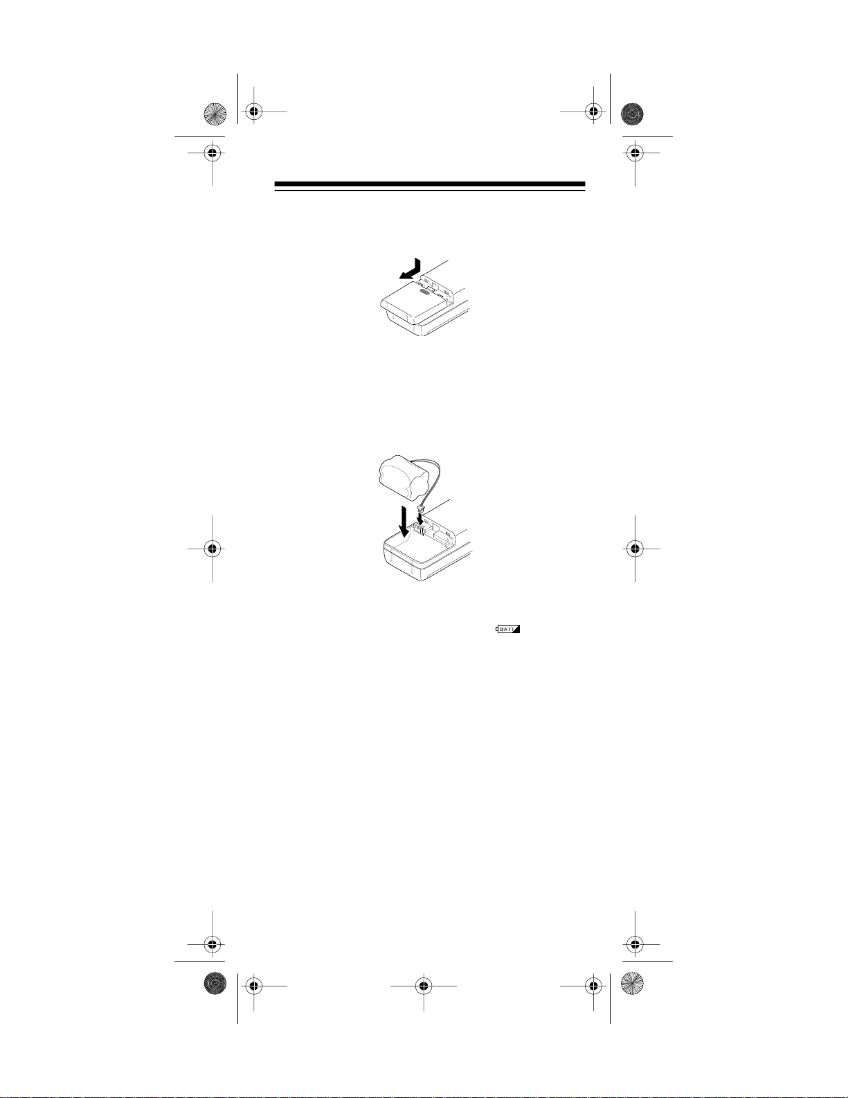
1. Press down on the battery compartment cover and
slide the cover in the direction of the arrow to
remove it.
2. Disconnect the battery pack’s connector from the
scanner’s connector. Then remove the battery pack
from the battery comp artment.
3. Attach the new battery pack's connector to the battery socket inside the battery compartment. Then
put the battery pack int o the compartment.
4. Replace the cover.
When the scanner’s battery gets low, blinks and
the scanner beeps about every 15 seconds.
Important: At the end of a rechargeable battery pack's
useful life, it must be recycled or disposed of properly.
Contact your local, county, or state hazardous waste
management authorities for information on recycling or
disposal prog rams in your area. Some options t hat might
be available are: municipal curb-side collection, drop-off
boxes at retailers such as your local RadioShack store,
recycling collection centers, and mailback programs.
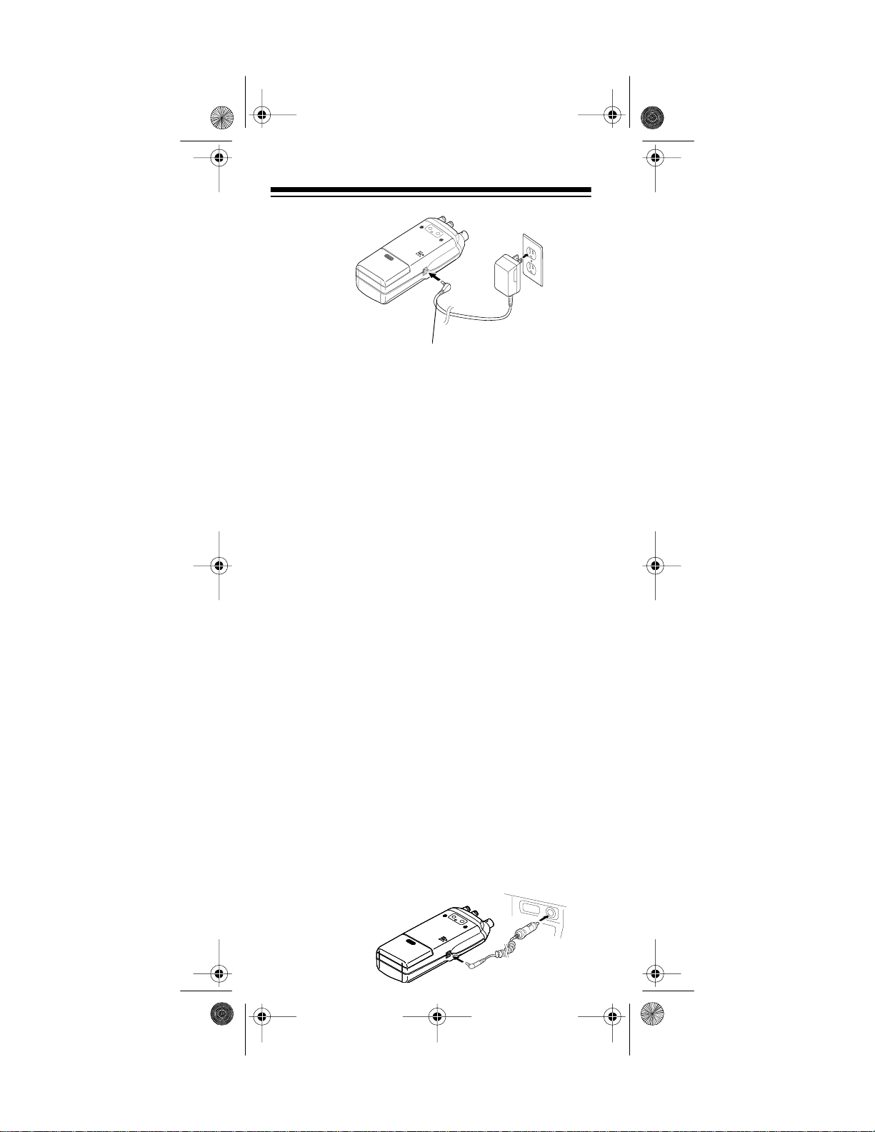
Using Standard AC Power
To power the scanner from AC power, use the supplied
AC adapter/charger. Plug the adapter/charger's barrel
plug into the scanner's
EXT. PWR
adapter/charger's power module into a standard AC outlet.
jack. Then plug the AC
9
Page 10
20-520 .fm Page 10 We dnesday, August 4, 19 99 3:06 PM
EXT. PWR Jack
Warning: Do not use t he AC adapter/charger's polarized
plug with an extension cord, receptacle, or other outlet
unless the blades can be fully inserted to prevent blade
exposure.
Caution: Use only the supplied AC adapt er/charger. It is
specifica ll y designed for this scan ner.
Using Vehicle Battery Power
To power the scanner from your vehicle's cigarette-lighter socket, you need a DC cigarette-lighter power cable,
such as Cat. No. 270-031 .
Cautions:
• The DC cigarette-lighter power cable must be capable of delivering 12 volts, its center tip must be set to
positive, and its barrel plug must correctly fit the
scanner's
EXT. PWR
jack. The recommended power
cable meets these specifications. Using a power
cable that does not meet these specifications could
damage the scanner or the power cable.
• To protect your vehicle's electrical system, always
plug the power cable into the scanner before you
plug it into your vehicle's cigarette-lighter socket.
Always unplug the power cable from the vehicle's
cigarette -l ighter socket before you un plug it from the
scanner.
• Insert the DC cigarette-lighter power cable's barrel
plug into the
EXT. PWR
jack, then plug the power
cable's othe r end into your vehicle' s cigarette-li ghter
socket.
.
10
Page 11
20-520 .fm Page 11 We dnesday, August 4, 19 99 3:06 PM
When you finish usi ng the DC cigarette-lighter power cable, disconnect it from the cigarette-lighter socket, then
disconnect it from your scanner.
Note: If the scanner does not operate properly when you
connect a DC cigarette-lighter power cable, unplug the
power cable from the cigarette-lighter socket and clean
the socket to remove ashes and other debris.
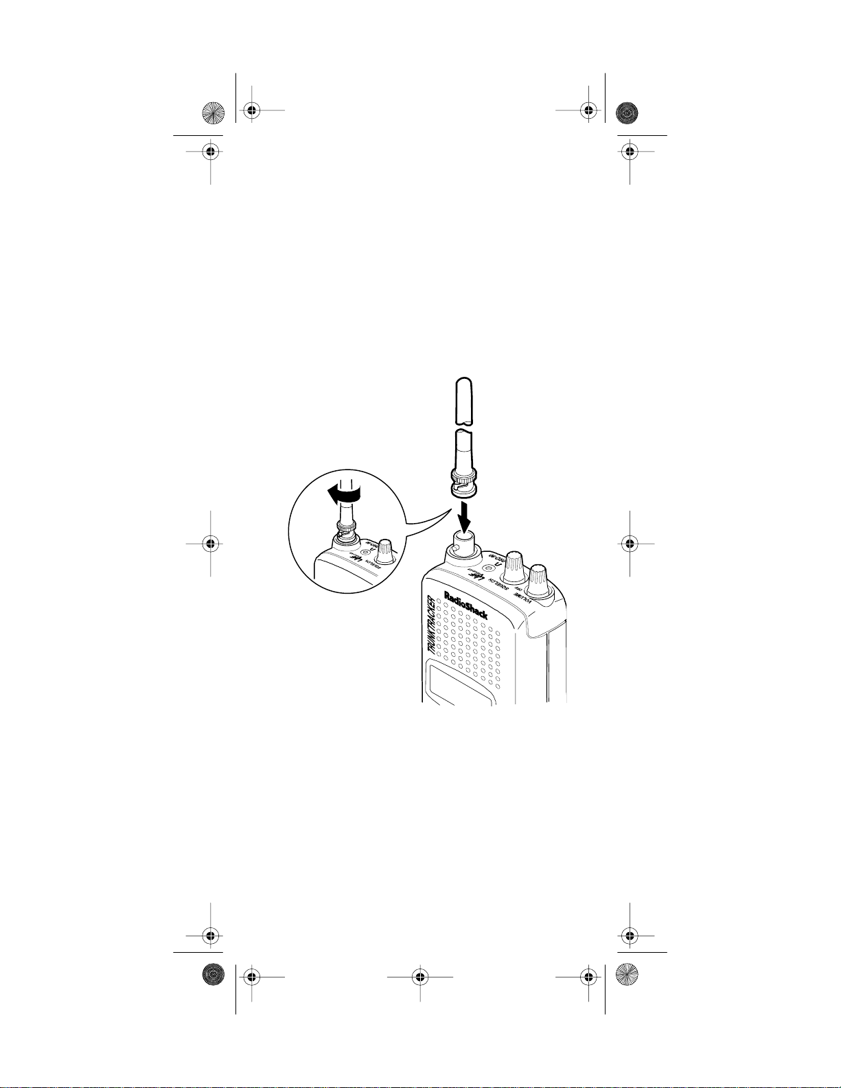
CONNECTING THE ANTENNA
Follow these steps to attach the supplied flexible antenna to the connector on the top of your scanner.
1. Align the slots around the antenna’s connector with
the tabs on the scanner’s BNC connector.
2. Slide the antenna’s connector down over the scanner’s connector and rotate the antenna connector’s
outer ring clockwise until it locks into place.
11
Page 12

20-520 .fm Page 12 We dnesday, August 4, 19 99 3:06 PM
Connecting an Optional Antenna
The scanner’s antenna jack makes it easy to use the
scanner with a variety of antennas. Instead of the supplied ante nna, you can att ach a different one, such as an
external mobile antenna or outdoor base station antenna. Your local RadioShack store sells a variety of antennas.
Always use 50-ohm coaxial cable, such as RG-58 or
RG-8, to connect an outdoor antenna. For lengths over
50 feet, use RG-8 low-loss dielectric coaxial cable. If
your antenna’s cable does not have a BNC connector,
use a BNC adapter available at your local RadioShack
store.
Follow the installation instructions supplied with the antenna, route the antenna cable to the scanner, then connect it to the antenna
jack.
Warning:
Use extreme caution when installing or removing an outdoor antenna. If the antenna starts to fall,
let it go! It could contact overhead power lines. If the antenna touches a power line, contact with the antenna,
mast, cable or guy wires can cause electrocution and
death! Call the power company to remove the antenna.
Do not attempt to do so yourself.
Cautions
:
• Do not run the cable over sharp edges or moving
parts.
• Do not run the cable next to power cables or other
antenna cables.
• Do not run the cable through a vehicle’s engine
compartment or other areas that produce extreme
heat.
• Follow all cautions and warnings included with the
antenna.
12
Page 13
20-520 .fm Page 13 We dnesday, August 4, 19 99 3:06 PM
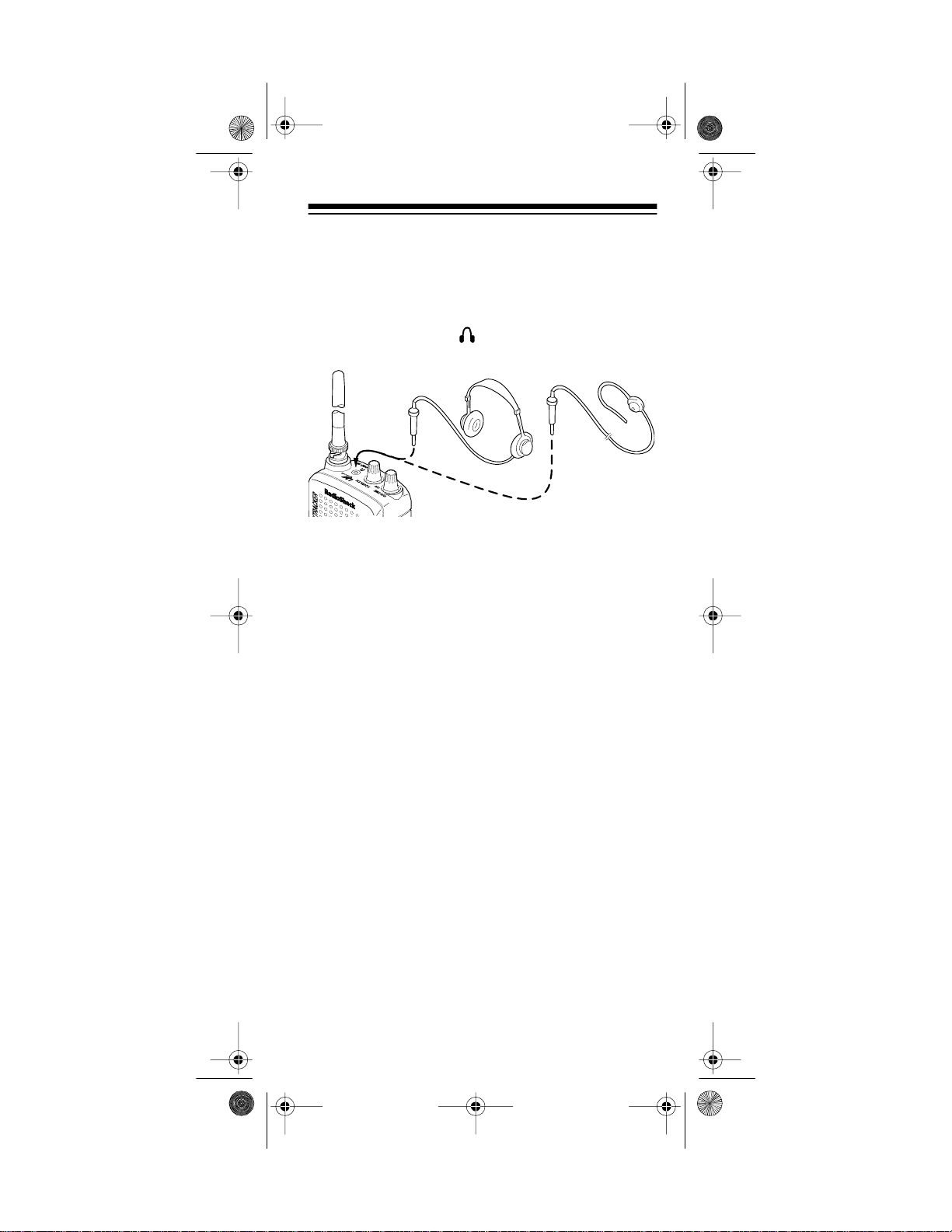
CONNECTING AN EARPHONE/
HEADPHONES
For private listening, you can plug an earphone or headphones with a
175 or 20-210) into the jack on top of your scanner.
This automatically disconnects the i nternal speaker.
1
/8-inch mini-plug (such as Cat. No. 33-
Listening Safely
To protect you r hearing, follow these guide lines when you
use an earphone or headphones.
• Do not listen at extremely high volume levels.
Exten ded hig h-volume listening can l ead to permanent hearing loss.
• Set the volume to the lowest setting before you
begin listening. After you begin listening, adjust the
volume to a comfortabl e level.
• Once you set the volume, do not increase it. Over
time, your ears adapt to the volume level, so a volume level that does not cause discomfort might still
damage your hearing.
Traffic Safety
Do not use an earphone/headphones with your scanner
when operating a motor vehicle or riding a bicycle in or
near traffic. Doing so can create a traffic hazard and
could be illegal in some areas.
If you use an earphone/headphones with your scanner,
be very careful. Do not listen to a continuous broadcast.
Even though some earphones/headphones let you hear
some outside sounds when listening at normal volume
levels, they still can present a tra ffic hazard.
13
Page 14
20-520 .fm Page 14 We dnesday, August 4, 19 99 3:06 PM
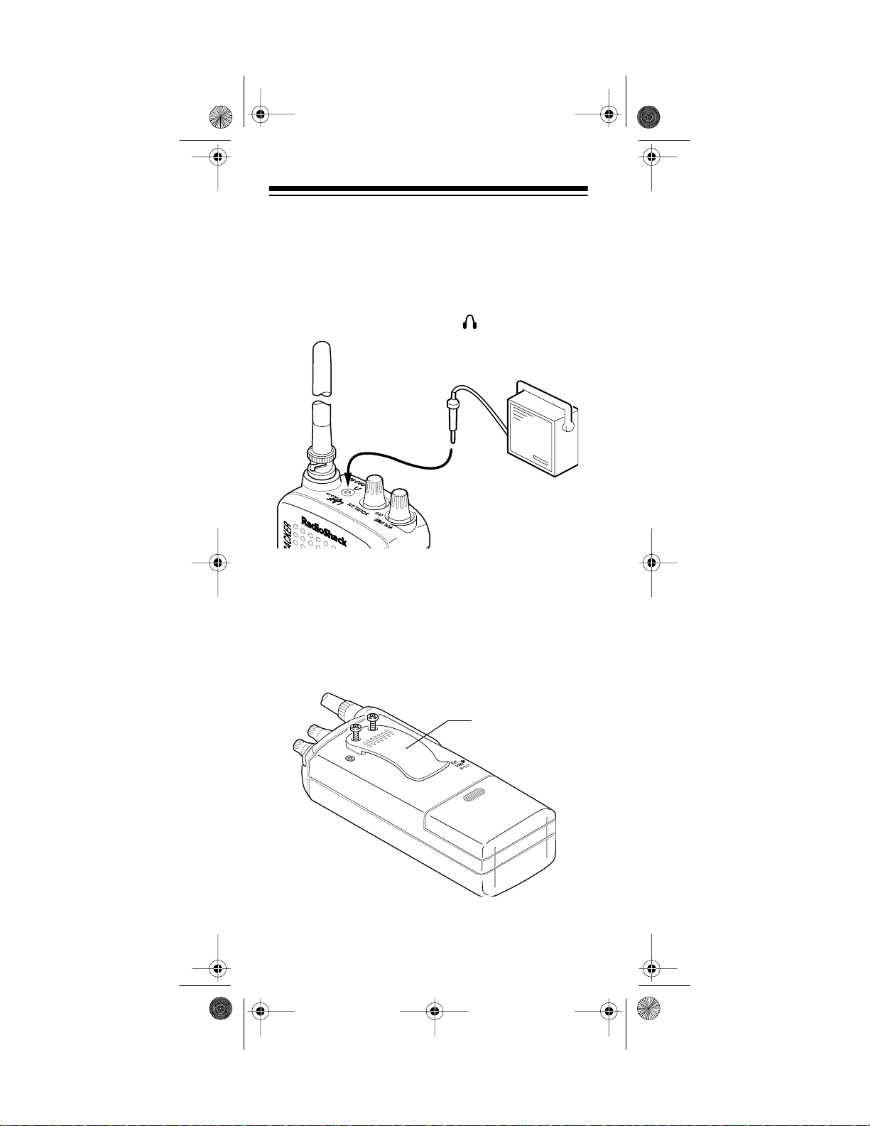
CONNECTING AN EXTENSION
SPEAKER
In a noisy area, an extension speaker (such as Cat. No.
21-549), positioned in the right place, might provide
more comfortable listening. Plug the speaker cable’s
inch mini-pl ug into your scanner ’s jack.
1
/8-
ATTACHING THE BELT CLIP
You can attach the supplied belt clip to make your scanner easier to carry when you are on the go. Use a Phillips screwdriver and the two supplied screws to attach
the belt clip to the scanner. Then slide the belt clip over
your belt or waistband.
Belt Clip
14
Page 15
20-520 .fm Page 15 We dnesday, August 4, 19 99 3:06 PM
UNDERSTANDING YOUR SCANNER
Once you understand a few simple terms we use in this
manual and familiarize yourself with your scanner’s
features, you c an put th e scanner to work for you. Yo u
simply find the communications you want to receive,
then set the scanner to scan them .
frequency
A
pressed in kHz or MHz). To find active frequencies, you
can use the
You can also search the service-search banks, w hich
are preset groups of frequencies catego rized by type of
service.
When you find a frequency, you can store it into a programmable memory location called a
with your other channels in a
can then
activity on the frequencies stored there. Each time the
scanner finds an active frequency, it stays on that channel
until the transmission ends.
is the tuning location of a station (ex-
search
function.
channel
channel-storage bank
scan
the channel-storage banks to see if there is
, which is grouped
. You
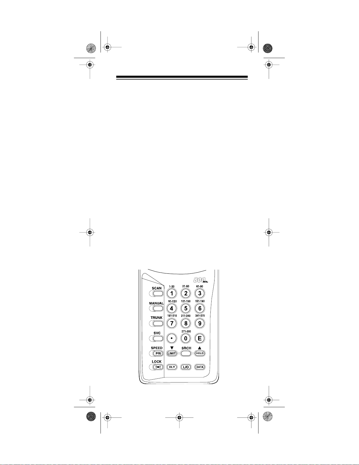
A LOOK AT THE KEYPAD
Your scanner’s keys might seem confusing at first, but
this information should help you understand each key’s
function.
15
Page 16

20-520 .fm Page 16 We dnesday, August 4, 19 99 3:06 PM
SCAN
— scans through the stored channels.
MANUAL
— stops scanning and lets you directly enter a
channel number or fr equency.
TRUNK —
switches between conventional and trunk
tracking modes.
SVC (service)
SPEED/PRI (speed/priority) —
— selects a service bank.
turns on and off the Hypersearch mode; sets and turns on and off the priority feature.
LOCK/
— locks the keypad to prevent acc idental program changes. Also turns on the display light for 15 seconds.
Number Keys — each key has a single-digit label and a
range of numbers. The single digits are used to enter a
channel, frequency, or ID number. The range of numbers (31–60, for example) indicates the channels that
make up a memory bank.
— enters a decimal point or clears an incorrect entry.
•
E (enter)
t
— enters frequencies into channels.
/LIMIT
— sets th e search direction and hol ds the frequen-
cy search; sets t he frequency range.
DLY (delay)
— programs a 2-second del ay for the selected
channel, a limit search, or each service scan. Also programs a 5–second delay in the trunk tracking mode.
SRCH
— searches a specified frequency range to find frequencies; searches for another active ID in the trunk
tracking mode.
L/O (lock out) —
lets you lock out selected channels or frequencies; lets you lock out a selected ID in the trunk
tracking mode.
s
/HOLD
— sets the search direction and holds the frequency sea rch; holds o n the current ID in th e trunk tra cking mode.
DATA
— turns on or off the data signal skip feature or
checks the current trunking bank in the trunk tracking
mode.
16
Page 17

20-520 .fm Page 17 We dnesday, August 4, 19 99 3:06 PM
A LOOK AT THE DISPLAY
The display has indicators that show the scanner’s current operating status. A good look at the display will help
you understand how your scanner operates.
— appears with numbers (1–10). Numbers with a
BANK
bar under them show which channel-storage banks are
turned on for scanning.
— appears when the scanner is in the trunk
TRUNK
tracking mode.
(channel activity indicators) — each represents a received trunking frequency or a data frequency in the
trunk trac king mode (see “Channel Acti vity Indicators” on
Page 40).
— appears when a priority channel is selected.
P
— blinks when the scanner’s battery is low.
— appears when the data skip function is act ive.
DATA
POLICE
bank.
FIRE/EMG
gency service bank.
AIR
MRN
bank.
WX
bank.
SCAN
— appears when you sear ch the police servi ce
— appears when you search the fire/emer-
— appears when you search the air ser vice bank.
— appears when you search the marine service
— appears when you search the weather service
— appears when you scan channels.
17
Page 18

20-520 .fm Page 18 We dnesday, August 4, 19 99 3:06 PM
— lights steadily during a limit search and ID
SRCH
search, and blinks while HyperSearch is active and
when you monitor IDs (see “Monitoring IDs” on
Page 39).
— appears when the priority feature is turned on.
PRI
— appears when you manually select a channel
HOLD
or when the scanner is in the hold mode during a search
or service bank scan or during a limit se arch.
— appears when you program a delay.
DLY
— appears when you manually select a channel or
L/O
frequency you loc ked out.
— appears when you lock the keypad.
— appears when you make an entry error.
Error
18
Page 19

20-520 .fm Page 19 We dnesday, August 4, 19 99 3:06 PM
UNDERSTANDING BANKS
Channel Storage Banks
To make it easier to identify and select the channels you
want to listen to, channels are divided into 10 banks of
30 channels each. Use each channel-storage bank to
group frequencies, such as the police department, fire
department, ambulance services, or aircraft (see “Guide
to the Action Bands” on Page52). For example, the police department might use four frequencies, one for each
side of town. You could program the police frequencies
starting with Channel 1 (the first channel in bank 1) and
program the fire department frequencies starting with
Channel 31 (the first channel in bank 2).
Service Banks
The scanner is preprogrammed with the frequencies allocated by police, fire/emergency, aircraft, marine, and
weather services. This is handy for quickly finding active
frequencies instead of searching through an entire band
(see “Scanning Service Banks” on Page 23).
UNDERSTANDING TRUNKING
In the past, groups that broadcast frequentl y, such as police departments, were restricted to transmitting on just a
few frequencies. This resul ted in heavy traffic and often
required 2-way radio users to wait for a specific frequency to clear befor e transmit ting.
Trunke d systems al low more gr oup s of 2-way ra di o u ser s
to use few er frequencies. Instead of selecti ng a specific
frequency to transmit on, a trunked system chooses one
of several frequencies when the 2-way radio user presses
PTT (push to talk). The system automatically transmits
the call on that frequency, and also sends a code that
identi fies that 2-way radio us er’s transmissio n on a data
channe l.
This scanner lets you select the data channel frequency
that you want it to monitor, so you can hear both the call
and response transmissions for that 2-way radio user
and therefore follow the conversation. (You cannot listen
to the data channel itself).
19
Page 20
20-520 .fm Page 20 We dnesday, August 4, 19 99 3:06 PM
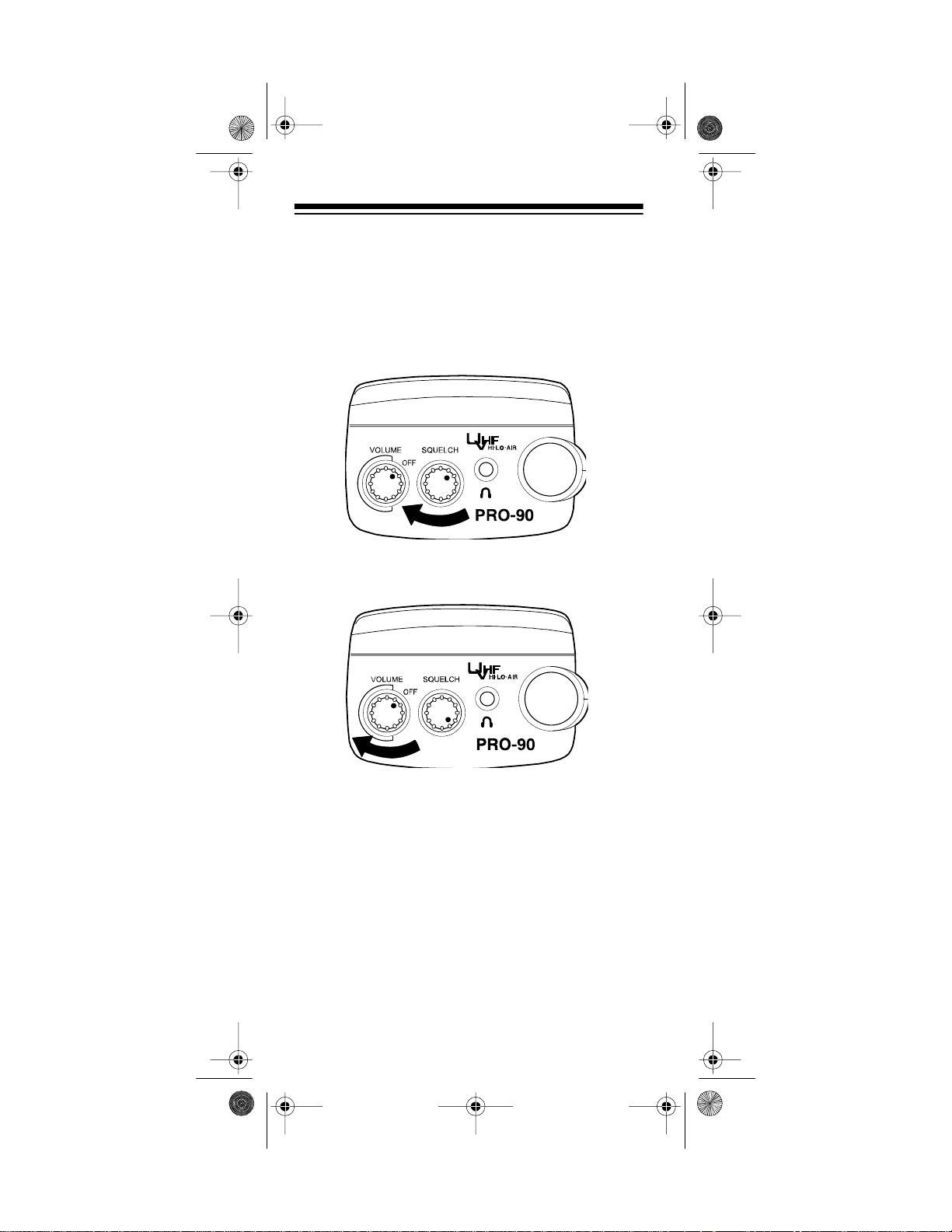
OPERATION
TURNING ON THE SCANNER
AND SETTING SQUELCH
Note:
Make sure the scanner's antenna is connected
before you turn it on.
1. Turn
2. Turn
3. Press
SQUELCH
VOLUME/OFF
hear a hissing sound.
then leave it set to a point just after the hissing
sound stops.
MANUAL
fully clock wise.
clockwise until it clicks and you
and turn
SQUELCH
counterclockwise,
20
Page 21

20-520 .fm Page 21 We dnesday, August 4, 19 99 3:06 PM
Notes:
• If you have not stored frequencies into any channels, the scanner does not scan.
• If the scanner picks up unwanted, partial, or very
weak transmissions, turn
to decrease the scanner's sensitivity to these signals. If you want to listen to a weak or distant station, turn
•If
sound, the scanner does not scan properly.
SQUELCH
SQUELC H
is adjusted so you always hear a hissing
SQUELCH
clockwise.
counterclo ckwise
STORING KNOWN FREQUENCIES
INTO CHANNELS
Good references for active frequencies are the RadioShack “Police Call Guide including Fire and Emergency Services,” “Official Aeronautical Frequency
Directory,” and “Maritime Frequency Directory.” We update these directories every year, so be sure to get a
current copy.
Note: To store trunking system frequencies, see “Programming Trunked Frequencies” on Page 34.
Follow these steps to store frequencies into channels.
1. Press
2. Use the number keys and
MANUAL
want to store a frequency, then press
The channel number appears.
(including the decimal point) you want to store.
, enter the c hannel number where you
MANUAL
to enter the frequency
•
again.
21
Page 22

20-520 .fm Page 22 We dnesday, August 4, 19 99 3:06 PM
3. Press E to store the frequency into the channel.
Notes:
• If you made a mistake in Step 2,
and the scanner beeps when you press
Error
appears
E
. Simply
start again from Step 2.
• Your scanner automatically rounds the entered
frequency to the nearest valid frequency. For
example, if you enter a frequency of 151.473,
your scanner accepts it as 151.475.
•Press
DELAY
if you want the scanner to pause 2
seconds on this channel after a transmission
ends before it proceeds to the next channel (see
“Delay” on Page 26). The scanner also stores
this setting in the channel.
4. If you want to program the next channel in
sequence, press
MANUAL
and repeat Steps 2 and 3.
LIMIT SEARCH
If you do not know a frequency to store, you can search
for transmissions within a range of frequencies you select, called the
any interesting frequencies you find into channels.
1. Press
want to store a frequency, then press
The channel number appears.
2. Use the number keys and
that is the lower limit of the range you want to
search.
3. Press
22
limit search range
MANUAL
, enter th e channel number where you
LIMIT
.
. Then you can store
to enter the frequency
•
MANUAL
again.
Page 23

20-520 .fm Page 23 We dnesday, August 4, 19 99 3:06 PM
4. Use the number keys and • to enter the frequency
that is the upper limit of the range you want to
search.
5. Press
LIMIT
, then press
SRCH
. The scanner begins to
search from the lower li mit to the upper limit.
6. When the scanner stops on a transmission, quickly
press either:
•E to store the displayed frequency into the chan-
nel. The scanner stores the frequency and continues searching.
• s or t to stop searching so you can listen to the
transmission.
HOLD
appears.
To release hold and continue searching, press
SRCH
.
Notes:
• To step through the frequencies while
HOLD
appears, press s or t.
• If you tune to a search skip frequency,
L/O
appears. See “Locking Out Channels and Frequencies” on Page 27.
• To skip data signals (such as modem signals), pre ss
DAT A
. See “Skipping Data Signa ls” on Page 31.
SCANNING SERVICE BANKS
You can scan for police, fire/emergency, aircraft, mar ine,
and weather transmissions even if you do not know the
specific frequencies that are used in you r are a. And, you
can store any of the fr equencies you find into channels.
23
Page 24

20-520 .fm Page 24 We dnesday, August 4, 19 99 3:06 PM
Your scanner has the following preprogrammed service
banks.
• POLICE — contains 1,079 polic e frequencies.
• FIRE/EMG — contains 280 fire and emergency service frequencies.
• AIR — contains 2,319 aircraft and air service frequencies.
• MRN contains 65 marine freque ncies.
• WX — contains 7 weather frequenci es.
To select a service bank, press
name
(POLICE, FIRE/EMG, AIR, MRN
SVC
. A service bank’s
, or
WX)
and
one of the preset police frequencies appear. After a 2second delay, scanning begins. To select another service bank, repeatedly press
SVC
until the scanner dis-
plays the name of the bank you want to use.
Notes:
• In the marine band, the active frequency and its
marine channel number alternately appear.
• To skip data signals ( such as modem signals), press
DATA
. See “Skipping Data Signal s” on Page 31.
• Because frequencies are not always assigned to the
same services everywhere, you might hear transmissions from one service in another service group.
If necessary, press SCAN
to start scanning immediately
or to continue sca nning if you want to skip a frequency.
During service-scan, you can press
scanning.
down one step, or press
appears. Press s or t to move up or
HOLD
SCAN
to resume sc anning.
HOLD
to pause the
Follow these steps to store frequencie s into channels.
MANUAL
.
1. Press
HOLD
appears.
2. Use the number keys t o enter the channel number
(1–300) where you want to store the frequency, then
MANUAL
press
3. Press
SVC
.
to select a s ervi ce bank an d beg in scanni ng .
4. When the scanner stops on a transmission, press
HOLD
. The frequency appear s.
5. Press
E
to store the frequency into the channel.
24
Page 25

20-520 .fm Page 25 We dnesday, August 4, 19 99 3:06 PM
SCANNING THE STORED CHANNELS
To begin scanning channels, press
SCAN
. The scanner
scans through all non-locked channels in the activated
banks. When the scanner finds a transmission, it stops
on it. When the transmission ends, the scanner res um es
scanning.
Note:
To scan in the trunk tracking mode, see “Scanning
a Trunked Bank” on Page 36.
MANUALLY SELECTING A CHANNEL
You can continuously monitor a single channel without
scanning. Thi s is useful if you hear an emergency broadcast on a channel and do not want to miss any details —
even though there might be periods of silence — or if
you want to monitor a specific channel.
Follow these steps to manually select a channel.
1. Press
2. Enter the channel number.
3. Press
Or, if your scanner is scanning and stops at the desired
channel, press
ditional times causes your scanner to step through the
channels.)
MANUAL
MANUAL
MANUAL
.
again.
one time. (Pressing
MANUAL
ad-
To resume scanning, pre ss
SCAN
.
DELETING A STORED FREQUENCY
1. Press
2. Use the number keys to enter the channel number
3. Press
Note:
locked out during scanning.
MANUAL
.
containing the frequency you want to delete. Then
MANUAL
press
again.
0
, then press E. The frequency is deleted.
Channels with no frequencies are automatically
25
Page 26

20-520 .fm Page 26 We dnesday, August 4, 19 99 3:06 PM
SPECIAL FEATURES
DELAY
Many agencies use a two-way radio system that might
have a period of 2 or more seconds between a query
and a reply. To keep from missing a reply, you can program a 2-second delay into any channel or frequency.
The scanner continues to monitor the frequency for 2
seconds after the transmission stops before resuming
scanning or searc hing.
To program a 2-second delay:
• If the scanner is scanning channel-storage banks
and stops on an active channel where you want to
.
DLY
DLY
before it continues
store a delay, quickly press
scanning again.
• If the desired channel is not
selected, manually select the
channel, then press
appears.
DLY
appears.
DL Y
• If the scanner is scanning service banks, press
while the scanner is scanning.
the scanner automati cally adds a 2-second delay
to every transmission it stops on in that band.
To turn off the 2-second delay, press
ner is monitoring the channel or scanning the service
banks.
disappears from the display.
DLY
appears and
DLY
DLY
while the scan-
DL Y
26
Page 27

20-520 .fm Page 27 We dnesday, August 4, 19 99 3:06 PM
TURNING CHANNEL-STORAGE
BANKS ON AND OFF
You can turn each channel-storage bank on and off.
When you turn off a bank, the scanner does not scan
any of the 30 channels in that bank.
While scanning, press the number key that corresponds
to the bank you want to turn on or off. If the bar under the
bank number is on, the bank is turned on and the scanner scans all channels within that bank that are not
locked out. If the bar is off, the scanner does not scan
any of the channels within that bank.
Notes:
• You can manually select any channel within a bank,
even if that bank is turn ed off.
• You cannot turn off all banks. One bank is always
active.
LOCKING OUT CHANNELS AND
FREQUENCIES
You can scan existing channels or search frequencies
faster by locking out channels or frequencies that have a
continuous tra nsm ission, such as a weather cha nnel.
Note:
If you jus t want to skip over a lengthy transmission
(such as a modem signal), see “Skipping Data Signals”
on Page 31.
Locking Out Channels
To lock out a channel while
scanning, press
scanner stops on the channel. To lock out a channel
manually, manually select
the channel and hold down
L/O
until
L/O
L/O
when the
appears.
L/O
27
Page 28

20-520 .fm Page 28 We dnesday, August 4, 19 99 3:06 PM
Note: You can still manually select locked-out channels.
To remove the lockout from a channel, manually select
the channel and hold down
L/O
until
disappears
L/O
from the display.
To unlock all channels in the banks that are turned on,
press
MANUAL
to stop scanning, then hold down
L/O
until
the scanner beeps twi ce.
Locking Out Frequencies
To lock out a frequency during a limit search or service
bank scan, press
quency. The scanner locks out the frequency, then continues searching. To lock out a frequency manually,
manually select the frequency and hold down
appears.
L/O
Notes:
• The scanner does not display locked-out frequen-
cies during a search.
• You can lock out as many as 20 frequencies during
a search. If you try to l ock out more than 20 freq uencies, the first locked-out frequency is automatically
unlocked.
when the scanner stops on the fre-
L/O
L/O
until
Follow these steps to remove the lockout from a frequency.
1. During a search, select the frequency you want to
remove the lockout from.
2. Press
L/O
.
disappears from the display.
L/O
To remove the lockout from all frequencies, while
searching, hold down
until the scanner beeps twice
L/O
(about 2 seconds).
PRIORITY
The priority feature lets you scan through channels and
still not miss important or interesting calls on specific
channels. You can program one stored channel in each
bank as a priority channel (for up to a total of 10 stored
channels). As the scanner scans the bank, if the priority
feature is turned on, the scanner checks the priority
channels for act ivity every 2 seconds.
28
Page 29

20-520 .fm Page 29 We dnesday, August 4, 19 99 3:06 PM
The scanner automatically designates each bank's first
channel as its priority channel. Follow these steps to select a dif fer ent channel as the priority channel for a bank.
1. Press
MANUAL
.
2. Enter the channel number you want to select as the
priority channel, then press
PRI
3. Hold down
until the scanner beeps twice.
MANUAL
again.
appears to the left of th e channel number .
4. Repeat Steps 2–3 for the channel in each bank you
want to program as a priorit y channel.
P
To turn on the priority feature, press
appears. Every 2 seconds the scanner checks the
PRI
PRI
during scanning.
priority channel in each bank that is turned on, starting
from the lowest to the highest-numbered priority channel.
To turn off the priority feature, press
PRI
.
PRI
disap-
pears.
Notes:
• The priority feature must be turned off to use the
data skip feature (see “Skipping Data Signals” on
Page 31).
• You can lock out priority channels. If you lock out all
priority channels,
P ch Loc Out
appears when
you turn on the priorit y feature.
29
Page 30

20-520 .fm Page 30 We dnesday, August 4, 19 99 3:06 PM
USING THE KEYLOCK
Once you program your scanner, you can protect it from
accidental program changes by turning on the keylock
feature. When locked, the only controls that operate are
SCAN, MANUAL, LOCK/
Note:
The keylock does not prevent the scanner from
scanning channels.
VOLUME/OFF
,
, and
SQUELCH
.
To turn on the keylock, hold down
appears. To turn it off, hold down
LOCK/
LOCK/
until
until
disappears.
USING THE DISPLAY BACKLIGHT
You can turn on the display backlight for easy vi ewing at
night. Press
LOCK/
to turn on the display backlight
for 15 seconds. To turn off the backlight before 15 seconds elapse, press the button again.
CHANGING SEARCH SPEEDS
The PRO-90 has two search speeds for a limit search.
Normal Search HyperSearch
100 steps/second 300 steps/second
30
Page 31

20-520 .fm Page 31 We dnesday, August 4, 19 99 3:06 PM
To switch between normal and HyperSearch speeds,
during a li m it search, press
ing hypersearch.
Note:
You can use HyperSearch only in the 5 kHz step
bands (29–54 MHz and 137–174 MHz).
SPEED/PRI
.
SRCH
flashes dur-
BATTERY SAVE
To save battery power when a channel is manually selected, the scanner’s battery save function automatically
sets the scanner to a standby mode if the scanner does
not receive any signals for more than 1 minute. During
the standby mode, the scanner repeatedly turns off the
internal power for 1 second then turns on the internal
power for about
sion.
1
/3 of a second to check for a transmis-
Note:
The scanne r’ s battery save function does not work
if the priority function is on, even if a channel is manua ll y
selected.
SKIPPING DATA SIGNALS
You can set the scanner so it skips nonmodulated or
data signals (such as modem transmissions) during a
search.
Note:
Since data signals are not generally found in the
air band, this featu re does not work in the air band.
To turn on the data skip feature, be sure the priority feature is turned off (see “Priority” on Page 28), then press
DATA
.
again.
appears. To turn off the feature, press
DATA
disappears.
DATA
DATA
31
Page 32

20-520 .fm Page 32 We dnesday, August 4, 19 99 3:06 PM
TRUNK TRACKING
Your scanner is designed to track transmissions on Motorola Type I, Type II, and hybrid analog trunking systems, which are extensively used in 800 MHz
communications. Remember these important points
when tracking transmissions:
• Your scanner monitors Type II systems by default.
However, you can change this if the system in your
area is different (see “Types of Trunking Systems”
below and “Scanning Type I and Hybrid Trunked
Systems” on Page 44 for more information).
• Your scanner cannot track transmissions on non-
Motorola trunking systems.
• Your scanner cannot track an 800 MHz trunked sys-
tem and scan frequencies in conventional mode at
the same time.
• The frequencies for many of the 800 MHz public
safety systems are listed in the separate “National
Public Safety Trunked System Frequency Guide”
included with your PRO-90.
TYPES OF TRUNKING SYSTEMS
Your trunk tracking scanner can monitor two basic types
of syste ms —
specific frequency to transmit on, a trunked system
chooses one of several frequencies in a 2-way radio user’s talk group when that use r presse s PTT (push to talk).
Thus, trunking systems allocate a few frequencies
among many different users, but the way Type I and
Type I I systems do this is slightly dif ferent. One important
distinction between these systems is the amount of data
transmitted by each radio when its push-to-talk button
(PTT) is pressed. In a Type I system, the radio’s ID and
its cur rent af filiati on (the trunk sy stem it belon gs to) are
both tran smitte d. In a Ty pe II syste m, on ly the rad io’s ID
is transmitted.
Why the differen ce? In Type I systems, each radio in the
trunk group i ndividually transm its its own affiliation, while
the trunk system maintains a database that determines
each radio's affiliation(s) in Type II systems.
Another difference between the systems is that Type I
systems are arranged in a fleet-subfleet hierarchy. For
example, it is possible for a city using a Type I system to
designate 4 fleets, each with 8 subfleets.
32
Type I
and
Type II
. Instead of selecting a
Page 33

20-520 .fm Page 33 We dnesday, August 4, 19 99 3:06 PM
The fleets might be the police department, the fire department, utilities, and city administration. The police
might decide to further divide its fleet into subfleets such
as dispatch, tactical operations, detectives, north, south,
east and west side patro ls, and supervi sors. All the avai lable police radios would then be assigned to one of the
police subfleets, letting the police centralize their communications and control the type of users on a single
system. Determining the exact fleet-subfleet hierarchy
for a particular area is referred to as fleet map programming.
The disadvantage of a Type I system is that the brief
burst of data sent when a user transmits must contain
the radio’s ID and its fleet and subfleet. This is three
times the amount of data a Type II system radio sends.
Since the data capacity of Type I systems is limited and
the amount of data increases wit h each user, Type I systems usually accommodate fewer users than Type II
systems. Nevertheless, Type I systems are still in use.
There are also
of both Type I and Type II. Your scanner defaults to
monitor Type II systems, but you can change to Type I or
a hybrid of Type I and Type II systems by selecting a
preprogrammed fleet map or creating a custom fleet
map for your area (see “Scanning Type I and Hybrid
Trunked Systems” on Page44).
You do not need to determine the fleet-subfleet hierarchy for Type II systems unless you are tracking hybrid
systems that contain both Type I and Type II systems.
hybrid
systems which are a combination
SETTING THE SCANNER TO THE
TRUNK TRACKING MODE
Repeatedly press
ner’s conventi onal and trunk tracking modes.
TRUNK
to switch between the scan-
33
Page 34

20-520 .fm Page 34 We dnesday, August 4, 19 99 3:06 PM
SETTING SQUELCH FOR THE
TRUNK TRACKING MODE
Your scanner’s squelch setting is automatically adjusted
in the trunking mode, which means it is not necessary to
manually adjust squelch while tracking trunked transmissions. However, the squelch setting can affect how fast
your scanner acquires the data c hannel, and, i n some instances, can prevent your scanner from acquiring the
data channel at al l.
We recommend you set
selecting a trunked bank.
Note:
You can change this setting, if necessary, to pro-
vide better performance in your area.
SQUELCH
to this position before
PROGRAMMING TRUNKED
FREQUENCIES
Before you progr am your scanner to track a trunked system, consider t he fol lowing:
• Valid trunked system frequencies range from
851.0125–868.9875 in 12.5 kHz steps.
• You can use a ny of your sc anner’ s banks as either a
trunk tracking bank or conventional scanning bank,
but you cannot mix the t wo.
• The scanner only scans one trunked system at a
time. Although you can store frequencies for more
than one trunked system in one of your scanner’s
banks, the scanner only scans the frequencies
associated with the first data channe l it finds.
Before scanning a trunked system’s transmissions, you
must store the trunked system’s frequencies in one of
the banks in your scanner by following these st eps.
34
Page 35

20-520 .fm Page 35 We dnesday, August 4, 19 99 3:06 PM
1. Hold down
BANK, TRUNK,
TRUNK
until the scanner beeps twice.
and the bank numbers flash.
2. Select the bank you want to store the trunked system’s frequencies in by pressing a number key. The
scanner automatically sel ects the first channel in the
bank when you select the bank.
3. Use the number keys to enter the trunked system’s
frequencies, then press
Note:
If you entered an invalid frequency in Step 3,
E
.
the scanner beeps, the channel num ber f lashes and
Error
appears. If this happens, press • to clear
the frequency, then repeat Step 3.
4. Press either
in the bank.
MANUAL
or s to select the next channel
35
Page 36

20-520 .fm Page 36 We dnesday, August 4, 19 99 3:06 PM
5. Repeat Steps 3 and 4 until all frequencies have
been entered.
6. Press
SRCH
to begin searching
for the trunk’s data channel (the
channel that controls the trunk).
flashes as the scanner
SRCH
searches for th e data channel.
While the scanner looks through
the frequencies, you see them
on the display. When the scanner finds the data channel, it
begins trunk tracking.
SCANNING A TRUNKED BANK
You can scan one trunked bank at a time. Once you
have stored frequencies for a trunked system in one or
more of the 10 available banks and you are scanning
non-trunked frequencies, follow these steps to begin
trunk scanning.
1. Press
TRUNK
. The indicator s for all banks flash.
2. Use the number keys to enter the number for the
trunked bank you want to scan, then press
SRCH
The scanner searches for a data channel. When the
scanner finds it, it begins trunk tracki ng.
If you entered all of the trunk’s frequencies, you
should be able to follow conversations between
broadcasters even when they change frequencies. IDs, which represent different service
groups , a pp ear.
ID
36
.
Page 37

20-520 .fm Page 37 We dnesday, August 4, 19 99 3:06 PM
Note: To review the bank currently in use, press
while in the trunk tracking mode. The bar for
DATA
the selected bank flashes at the top of the display
for about 5 seconds.
3. To return to non-trunked scanning, press
TRUNK
again.
Hint: While scanning, you will not know exactly who the
ID's are assigned to until you listen awhile or until you locate ID lists in frequency guides or on internet sit es such
as
www.trunkscanner.com
. Within a few minutes, you
can usually figure out if what you are listening to is a police, fire, or emergency medical 2-way radio user. Other
IDs might take some time, but determining who each ID
represents is half the fun of trunk trackin g!
Monitoring an Active ID
When the scanner stops on a transmission, you can hold
the scanner on that transmission.
1. Press
HOLD
.
HOLD
appears, the scanner stays on
the current ID, and the channel number changes.
2. If you want t o listen to a different ID, use the number
keys to enter the ID you want to hol d.
3. Press
HOLD
again.
flashes and the scanner
HOLD
monitors that ID.
4. When you want to stop t he hold and r esume searching for a data channel so you can continue trunk
tracking, pr ess
SRCH
.
Note: You can also follow these steps to hold on an ID
while scanning a scan list. See “Scan Lists” on Page 41.
37
Page 38

20-520 .fm Page 38 We dnesday, August 4, 19 99 3:06 PM
Locking Out IDs
As with conventional scanning, it is possible to lock out
unwanted traffic. This is particularly important in trunked
systems because signals you cannot listen to (such as
water meters, door alarms, traffic signals, and encrypted
signals) are assigned IDs just like other users. You can
have up to 100 IDs locked out at one tim e.
Note:
If you lock out an ID while searching, it is also
locked out of the scan list(s). See “Scan Lists” on
Page 41.
To lock out an ID, press
when the ID appears.
L/O
The ID is locked out, and the next active ID appears.
Unlocking a Single ID
1. Hold down
2. Repeatedly press t or s to select the ID you want to
unlock.
3. Press
L/O
The ID is unlocked and the next locked ID or
– –––
4. Press
SRCH
tion.
until you hear two short beeps.
L/O
.
(if there are no other locked IDs) appears.
to continue th e scanner’s previous f unc-
Unlocking All IDs
Hold down
press
to unlock all the IDs at once.- The scanne r beeps
E
twice.
until you hear two short beeps. Then
L/O
–
Note:
When you unlock all the IDs, the scan list mode
appears. Press
lists or press
to scan the IDs stored in your scan
SCAN
to continue the scanner’s previous
SRCH
function. For more information about scan lists, see
“Scan Lists” on Page 41.
38
Page 39

20-520 .fm Page 39 We dnesday, August 4, 19 99 3:06 PM
Using Trunk Tracking Scan Delay
Many trunked systems have a period of 2 or more seconds between a query and a reply. You can program a
5-second delay to hold on an ID for 5 seconds to wait for
a reply. The scanner continues to monitor the frequency
for 5 seconds aft er the transmissio n stops before resum ing scanning.
Press
DLY
Note:
to turn trunk tracking scan delay on or off.
DLY
appears when trunk tracking scan delay is set.
If you consistently miss responses even with trunk
tracking scan delay set, you might need to change the
default system type or the fleet map you are using. See
“Scanning Type I and Hybrid Trunked Systems” on
Page 44.
Monitoring IDs
You can use your scanner’s display to monitor the frequencies in a trunked system for activity. You cannot
hear conversations in this mode, but this is an excellent
way to determine which talk groups are the most active.
To set the scanner to monitor IDs, hold down
the scanner beeps twice.
flashes, and all active
SRCH
talk group IDs appear in succession. To stop monitoring
IDs, press
SRCH
again.
SRCH
until
Note:
When you monitor IDs, locked-out IDs also ap-
pear.
39
Page 40

20-520 .fm Page 40 We dnesday, August 4, 19 99 3:06 PM
CHANNEL ACTIVITY INDICATORS
Your scanner has 20 channel activity indicators (bars)
which show the activity taking place on a trunked system. You can see how many frequencies are being used
and generally monitor how much communication traffic
is occurrin g.
Each frequency you store in a trunking bank has a corresponding activity indicator. However, since there are
only 20 indicators, but you can store up to 30 frequencies, some indicators might indicate more than one frequency if th e trunked syste m you are scanning ha s m ore
than 20 channels.
• The indicator that remains on steadily even when
there are no current transmissions represents the
frequency being used as the data channel.
• The indicator that flashes when an ID appears rep-
resents the frequency being used by the radio you
are currently hearing.
• If an indicator turns on but you do not hear a conver-
sation, the cha nnel is probabl y being used f or a telephone interconnect call or a private call, or the
indicator might be a locked-out ID. Your scanner
does not monitor t hese types of calls.
• If the scanner is holding on an ID which is not
active, t he other activity indicators tu rn on and off as
other groups use the system.
40
Page 41

20-520 .fm Page 41 We dnesday, August 4, 19 99 3:06 PM
SCAN LISTS
When you program trunked frequencies into a bank ( see
“Programming Trunked Frequencies” on Page 34), your
scanner sets up 5 scan lists into which you can store
your favorite IDs. Each list can contain up to 10 IDs, so
you can store a total of 50 IDs for each trunk tracking
bank (500 IDs if you use all banks as trunking banks!).
Scan lists help you organize trunking system users into
categories. For example, you might use List 1 for police
IDs, List 2 for fire department IDs, List 3 for emergency
medical service IDs, and so on. Once IDs are stored in
lists, you can scan them like you scan conventional
channels. You can program IDs into scan lists manually,
during a search, or automatically.
Manually Storing IDs into Scan Lists
1. Select the trunking bank you want (see “Scanning a
Trunked Bank” on Page36).
2. After the scanner begins trunk tracking, press
UAL
. A bar appears at the top of the display, showing
the current scan list.
MAN-
3. Repeatedly press s or t to select the scan list location (shown at the top of the display) you want to
program.
41
Page 42

20-520 .fm Page 42 We dnesday, August 4, 19 99 3:06 PM
4. Enter the Type II ID you want to store, then press E.
Or, to enter a Type I ID:
a. Use the number keys to enter the block number
and the fleet number, then press
b. Enter the subfleet number, then press
Note:
To clear a mistake while ent eri ng an ID, press
twice, then start over at Step 1.
•
5. Repeatedly press
scan list location you want to program. Then repeat
Step 4 to enter another ID.
MANUAL
.
•
E
.
or s to select the next
Storing IDs Into Scan Lists While Searching
Follow thes e steps to select a scan list location and store
an ID during a search.
1. When your scanner stops on an ID you want to
store, press
memory location flashes.
2. Press E to store the ID in the selected scan list
memory location. Or, repeatedly press s or t to
select the scan l ist memory location you want, then
press
3. Press
PRI
. The currently selected scan list
E
.
SRCH
to resume searching.
Automatically Storing an ID in a Scan List
Location
Follow these steps to store an ID in the first empty scan
list location during a search.
1. When your scanner stops on an ID you want to
store, press
played scan lis t l ocation.
42
E
. The scanner stores the ID in the dis-
Page 43

20-520 .fm Page 43 We dnesday, August 4, 19 99 3:06 PM
2. Press
SRCH
to resume searching.
Deleting a Stored ID
1. Repeatedly press s or t to select the scan list location (shown at the top of the display) you want to
delete.
2. Press
0
then E.
SCANNING THE SCAN LISTS
SCAN
Press
gram med.
Note:
on the display but your scanner does not stop on an active conversation.
to begin scanning the lists you have pro-
If you haven't programmed any IDs,
SCAN
scrol ls
To remove a scan list from active scanning, use the
number keys to enter the scan list’s number. The scan
43
Page 44

20-520 .fm Page 44 We dnesday, August 4, 19 99 3:06 PM
list indicator turns off, and the IDs in that list are not
scanned.
Note: One scan list must always be active. If you try to remove all the scan lists, the first scan list will stay active.
To restore a scan list to active scanning, use the number
keys to enter its number again.
Press
To alternate the display between the channel activity in-
dicators and the scan list indicators, press
to return to the scanner’ s previous function.
SRCH
PRI
.
SCANNING TYPE I AND HYBRID
TRUNKED SYSTEMS
Your PRO-90 is set to scan Type II user IDs by default.
When you scan trunked frequencies, each Type II user
ID you see appears as an even number without a dash
(such as 2160). Your PRO-90 can also scan Type I
trunked systems. Each Type I ID appears as a three- or
four-digit number, followed by a hyphen, followed by a
one- or two-digit number (such as 200-14). If you notice
a mix of odd- and even-user IDs (such as 6477, 2160,
6481, 6144, and 1167), then you are probably monitoring either a Type I or hybrid (a combination of Type I and
Type 2 user IDs) system (see “Types of Trunked Systems” on Page 32).
You might also notice that you are missing responses
when you hold on an active ID. Unlike Type II systems,
Type I and hybr id systems require a fleet map that sets
specific fleet-subfleet parameters. It is easy to select a
fleet map to s can; what is not alway s easy is selecting or
programming a map that is being used in your particular
area.
When a Type I system is designed, the address information for all i ts user IDs is divided into 8 equal-size blocks,
numbered 0–7, and each block is assigned a size code.
44
Page 45

20-520 .fm Page 45 We dnesday, August 4, 19 99 3:06 PM
When you set up your scanner to track a Type I system,
you must choose a size code for each block. When you
have chosen a size code for all 8 blocks, you will have
duplicated the
fleet map
for the system you are tracking.
If you have chosen correctly, you will be able to track
transmissions in that system.
Each size code defines the number of fleets, subfleets,
and IDs each block has. For example, you can see in the
following table that a size code of S-4 has one fleet,
which is divided into 16 separate subfleets, and it has a
total of 512 indivi dual IDs.
Size Fleets Subfleets IDs Block
Used
S-0 Reserved block for Type II IDs
S-1 128 4 16 1
S-2 16 8 64 1
S-3 8 8 128 1
S-4 1 16 512 1
S-5 64 4 32 1
S-6 32 8 32 1
S-7 32 4 64 1
S-8 16 4 128 1
S-9 8 4 256 1
S-10 4 8 256 1
S-11 2 16 256 1
S-12 1 16 1024 2
S-13 1 16 2048 4
S-14 1 16 4096 8
Each ID in the block is unique. The left-most digit is the
block number in the ID. The next two digits identify which
fleet is active, and the last digit(s) (after the hyphen)
identifies t he subfleet.
The size codes select ed by a Type I syst em desi gner de pend on the specific needs of the system's users. Some
organizations might want many subfleets with only a few
radios each, while another organization might want only
a few subfleets, with many radios each. To scan Type I
45
Page 46

20-520 .fm Page 46 We dnesday, August 4, 19 99 3:06 PM
systems, you must select or program a fleet map with
the same size code assignments as the trunked system.
If you d o this ac curatel y, you w ill track a ll the flee t and
subfleet combinations used by the system. In other
words, you will hear complete communications while
monitoring a trunked system.
Note: Preset fleet maps might be available at
www.trunkscanner.com
.
If you do not already know the size codes used, you will
have to guess them. But since you do not have to figure
out all the blocks at once, this is not as hard as it seems.
Select a size code for a block, then press
SRCH
. Now listen to the communications. If you decide you are receiving most of the replies to the conversations with IDs
assigned to the block you just programmed, then you
have probably selected the right size code and can work
on the next block of the ma p.
There are 16 preset fleet maps to choose from, and it is
best to start with these when setting up a Type I or hybrid trunk tracking bank. If none of the following preset
fleet maps allow you t o follow complete conversations,
then you probably need to program your own fleet map
(see “Programming a Fleet Map” on Page 49).
E1P1 E1P2 E1P3
Block Size
Code
Block Size
Code
Block Size
Code
0S110S40S4
1S111S41S4
2S112S42S4
3S113S43S4
4S114S44S4
5S115S45S4
6S116S46S12
7S117S47---
E1P4 E1P5 E1P6
Block Size
Code
Block Size
Code
Block Size
Code
0S120S40S3
46
Page 47

20-520 .fm Page 47 We dnesday, August 4, 19 99 3:06 PM
1---1S41S10
2 S4 2 S12 2 S4
3S43---3S4
4S44S44S12
E1P4 E1P5 E1P6
Block Size
Code
Block Size
Code
Block Size
Code
5S45S45--6S46S46S12
7S47S47---
E1P7 E1P8 E1P9
Block Size
Code
Block Size
Code
Block Size
Code
0S100S10S4
1S101S11S4
2S112S22S0
3S43S23S0
4S44S34S0
5S45S35S0
6S46S46S0
7S47S47S0
E1P10 E1P11 E1P12
Block Size
Code
Block Size
Code
Block Size
Code
0S00S40S0
1S01S01S0
2S02S02S0
3S03S03S0
4S04S04S0
47
Page 48

20-520 .fm Page 48 We dnesday, August 4, 19 99 3:06 PM
5S05S05S0
6S46S06S0
7S47S07S4
E1P13 E1P14 E1P15
Block Size
Code
Block Size
Code
Block Size
Code
0S30S40S4
1S31S31S4
2S112S102S4
3S43S43S11
4S44S44S11
5S05S45S0
6 S0 6 S12 6 S12
7 S0 7 --- 7 ---
E1P16
Block Size
Code
0S3
1S10
2S10
3S11
4S0
5S0
6S12
7---
Selecting a Preset Fl eet Map
1. Select the bank where you want to store the preset
fleet map by pressi ng a num ber key.
48
Page 49

20-520 .fm Page 49 We dnesday, August 4, 19 99 3:06 PM
DATA
DATA
again.-
.
, then press
E1
2. Press
3. Repeatedly press s or t to select
4. Repeatedly press s or t to select the name of the
map you want (such as
), then press E.
P7
The scanner then searches for transmissions using the
preset map you chose.
Note:
When the scanner searches for transmissions,
you see Type I fleet and subfleet IDs such as
100-9, 000-12
, or
400-8
.
100-12
How do you know if the preset map you selected is correct? Listen to see if you are following complete conversations. If not, try another preset map.
,
Programming a Fleet Map
1. Select the bank where you want to program the fleet
map by pressing a number key.
DAT A
.-
DATA
DATA
.
appears, then press
E1
appears.
USr
.
2. Press
3. Repeatedly press s or t until
4. Repeatedly press s or t until
5. Press
49
Page 50

20-520 .fm Page 50 We dnesday, August 4, 19 99 3:06 PM
6. Repeatedly press s or t to select the size code for
the first block, then press
E
.- The next available
block appears.
7. Repeat Step 6 until you have selected a size code
for each block you want to work with.
8. Press
SRCH
. The scanner exits the trunking programming mode, tunes the data channel, then
begins to search us ing the map you programmed.
Note:
If you select size code S-12, S-13, or S-14, these re-
strictions apply:
• S-12 can only be assigned to Blocks 0, 2, 4, or 6.
• S-13 can only be assigned to Blocks 0 and 4.
• S-14 can only be assigned to Block 0.
Since these size codes require multiple blocks, you will
be prompted for the next available block when programming a fleet map. For example, if you assign Block 0 as
an S-12, the scanner prompts you for
, the next block
b2
available, instead of b1. And if you assign Block 0 as an
S-14, you would not see another prompt because it uses
all available blocks.
Programming a Hybrid System
A hybrid system is simply a Type I system with some of
its blocks designated as Type II blocks. To program a
hybrid system, follow the steps listed in “Programming a
Fleet Map” on Page 49. However, if you want a block to
be Type II, select size code
S-0
in Step 6.
50
Page 51

20-520 .fm Page 51 We dnesday, August 4, 19 99 3:06 PM
A GENERAL GUIDE TO SCANNING
Reception of the frequencies covered by your scanner is
mainly “line-of-sight.” That means you usually cannot
hear stations that are beyond the horizon.
GUIDE TO FREQUENCIES
National Weather Frequencies
162.400 162.475 162.525
162.425 162.500 162.550
162.450
Canadian Weather Frequencies
161.650 161.775 163.275
Note:
These frequencies are not pre-programmed in the
weather service bank but can be manually pr ogrammed
into a channel.
Birdie Frequencies
Every scanner has birdie frequencies. Birdies are signals created inside the scanner’s receiver. These operating frequencies might interfere with broadcasts on the
same frequencies. If you program one of these frequencies, you hear only noise on that frequency. If the interference is not severe, you might be able to turn
clockwise to cut out the birdie. This scanner’s birdie frequencies (in MHz) are:
41.6000 406.2000 438.4000 489.2500
118.8875 413.1750 445.8250 495.3625
138.7000 413.2250 445.8375 496.3750
138.7050 416.1125 455.7375 813.4000
158.5150 426.0125 465.6500 852.0375
158.5200 426.0250 475.5500 899.2375
168.4250 435.9250 485.4625 926.7000
SQUELCH
51
Page 52

20-520 .fm Page 52 We dnesday, August 4, 19 99 3:06 PM
GUIDE TO THE ACTION BANDS
Ty pical Band Usage
VHF Band
Low Range 29.00–50.00 MHz
6-Meter Amateur 50.00 –54.00 MHz
U.S. Government 137.00–144.00 MHz
2-Meter Amateur 144.00– 148.00 MHz
High Range 148.00–174. 00 MHz
UHF Band
U.S. Government 406.00–420.00 MHz
70-cm Amateur 420.00–450.00 MHz
Low Range 450.00–470.00 MHz
FM-TV Audio Broadcast, Wide
Band
Public Service 806.00–823.93 MHz
Conventional Systems 851.00–856.00 MHz
Conventional/Trunked Systems
Trunked Systems 861.00–866.00 MHz
Public Safety 866.00–868.93 MHz
High Range 896.11–902.00 MHz
33-Centimeter Amateur 902.00–928.00 MHz
Private Trunked 935.00–940.00 MHz
General Trunked 940.0 0–941.00 MHz
Fixed Services 941.00–944.00 MHz
Studio-to-Transmitter Broadcast Links
Private Fixed Services, Paging 952.00–960.00 MHz
Aeronautical Navigation 960.00–1000.00 MHz
470.00 –512.0 0 MH z
856.00 –861.0 0 MH z
944.00 –952.0 0 MH z
Primary U sage
As a general rule, most of the radio activit y is concentrated on the f ollowing frequencies:
VHF Band
Activities Frequencies
Government, Police, and Fire 153.785–155.980 MHz
Emergency Services 158.730–159.460 MHz
Railro ad 160.00 0– 161.90 0 MH z
52
Page 53

20-520 .fm Page 53 We dnesday, August 4, 19 99 3:06 PM
UHF Band
Activities Frequencies
Land-M obile “Paired” Frequenci es
Base Stations 451.025–454.950 MHz
Mobile Units 456.025–459.950 MHz
Repeater Units 460.025–464.975 MHz
Contro l Stations 465.025–469.975 MHz
450.000–470.000 MHz
Note: Remote control stations and mobile units operate
at 5 MHz higher than their associated base stations and
relay repeater units.
BAND ALLOCATION
To help decide which frequency ranges to scan, use the
following listing of the typical services that use the frequencies your scanner receives. These frequencies are
subject to change, and might vary from area to area. For
a more complete listing, refer to the “Police Call Radio
Guide including Fire and Emergency Services,” available
at your local RadioShack store.
Abbreviations Services
BIFC . . . . . . . . . . . . . . . . . . Boise (ID) Interagency Fire Cache
BUS. . . . . . . . . . . . . . . . . . . . . . . . . . . . . . . . . . . . . . . Business
CAP. . . . . . . . . . . . . . . . . . . . . . . . . . . . . . . . . . . Civil Air Patrol
CB . . . . . . . . . . . . . . . . . . . . . . . . . . . . . . . . . . . . Citizens Band
CCA. . . . . . . . . . . . . . . . . . . . . . . . . . . . . . . . . Common Carrier
CSB. . . . . . . . . . . . . . . . . . . . . . . . . . . . .Conventional Systems
CTSB. . . . . . . . . . . . . . . . . . . . .Conventional/Trunked Systems
FIRE . . . . . . . . . . . . . . . . . . . . . . . . . . . . . . . . .Fire Department
HAM . . . . . . . . . . . . . . . . . . . . . . . . . . . . Amateur (Ham) Radio
GOVT . . . . . . . . . . . . . . . . . . . . . . . . . . . . Federal Government
GMR . . . . . . . . . . . . . . . . . . . . . . . . . . . . General Mobile Radio
GTR. . . . . . . . . . . . . . . . . . . . . . . . . . . . . . . . . General Trunked
IND . . . . . . . . . . . . . . . . . . . . . . . . . . . . . . . . Industrial Services
(Manufacturing, Construction, Farming, Forest Products)
MAR . . . . . . . . . . . . . . . . . . . . . . . . . . . Military Amateur Radio
MARI . . . . . . . . . . . . . . . . . . . . . . . . . . . Maritime Limited Coast
MARS . . . . . . . . . . . . . . . . . . . . .Military Affiliate Radio System
MED . . . . . . . . . . . . . . . . . . . . . . Emergency/Medical Services
MIL . . . . . . . . . . . . . . . . . . . . . . . . . . . . . . . . . . . . .U.S. Military
MOV . . . . . . . . . . . . . . . . . . . . . . Motion Picture/Video Industry
NEW . . . . . . . . . . . . . . . . . . . . . . . . . . . . . . New Mobile Narrow
NEWS . . . . . . . . . . . . . . . .Relay Press (Newspaper Reporters)
OIL. . . . . . . . . . . . . . . . . . . . . . . . . . . . . .Oil/Petroleum Industry
POL . . . . . . . . . . . . . . . . . . . . . . . . . . . . . . . .Police Department
PUB. . . . . . . . . . . . . . . . . . . . . . . . . . . . . . . . . . Public Services
(Public Safety, Local Government, Forestry Conservation)
PSB . . . . . . . . . . . . . . . . . . . . . . . . . . . . . . . . . . . . Public Safety
(Coast Guard, Mar ine Telephone,
Shipboard Radio, Private Stations)
53
Page 54

20-520 .fm Page 54 We dnesday, August 4, 19 99 3:06 PM
PTR . . . . . . . . . . . . . . . . . . . . . . . . . . . . . . . . . . Private Trunked
ROAD . . . . . . . . . . . . . . . . . . . . Road & Highway Maintenance
RTV . . . . . . . . . . . . . . . . . .Radio/TV Remote Broadcast Pickup
TAXI. . . . . . . . . . . . . . . . . . . . . . . . . . . . . . . . . . . . Taxi Services
TELB . . . . . . . . . . . . . . . . . . . . . . . . . . . . . . . Mobile Telephone
. . (Aircraft, Radio Common Carrier, Landline Companies)
TELC . . . . . . . . . . . . . . . . . . . . . . . . . . . . . . . . Cordless Phones
TELM. . . . . . . . . . . . . . . . . . . . . . . . . . Telephone Maintenance
TOW . . . . . . . . . . . . . . . . . . . . . . . . . . . . . . . . . . . . Tow Trucks
TRAN. . . . . . . . . . . . . . . . . . . . . . . . . . .Transportation Services
. . . . . . . . . . (Trucks, Tow Trucks, Buses, Railroad, Other)
TSB . . . . . . . . . . . . . . . . . . . . . . . . . . . . . . . . .Trunked Systems
TVn . . . . . . . . . . . . . . . . . . . . . . . . . . . FM-TV Audio Broadcast
USXX. . . . . . . . . . . . . . . . . . . . . . . . . . . Government Classified
UTIL. . . . . . . . . . . . . . . . . . . . . . . . . . . . Power & Water Utilities
WTHR . . . . . . . . . . . . . . . . . . . . . . . . . . . . . . . . . . . . . .Weather
VERY HIGH FREQUENCY (VHF)
VHF Low Band—(29–50 MHz—in 5 kHz steps)
29.000–29.700 . . . . . . . . . . . . . . . . . . . . . . . . . . . . . . . . . .HAM
29.900–30.550 . . . . . . . . . . . . . . . . . . . . . . . . . . . . .GOVT, MIL
30.580–31.980 . . . . . . . . . . . . . . . . . . . . . . . . . . . . . .IND, PUB
32.000–32.990 . . . . . . . . . . . . . . . . . . . . . . . . . . . . .GOVT, MIL
33.020–33.980 . . . . . . . . . . . . . . . . . . . . . . . . . BUS, IND, PUB
34.010–34.990 . . . . . . . . . . . . . . . . . . . . . . . . . . . . .GOVT, MIL
35.020–35.980 . . . . . . . . . . . . . . . . . . . BUS, PUB, IND, TELM
36.000–36.230 . . . . . . . . . . . . . . . . . . . . . . . . . . . . .GOVT, MIL
36.250 . . . . . . . . . . . . . . . . . . . . . . . . . . . . . . . Oil Spill Cleanup
36.270–36.990 . . . . . . . . . . . . . . . . . . . . . . . . . . . . .GOVT, MIL
37.020–37.980 . . . . . . . . . . . . . . . . . . . . . . . . . . . . . .PUB, IND
38.000–39.000 . . . . . . . . . . . . . . . . . . . . . . . . . . . . .GOVT, MIL
39.020–39.980 . . . . . . . . . . . . . . . . . . . . . . . . . . . . . . . . . .PUB
40.000–42.000 . . . . . . . . . . . . . . . . . . . . . . . GOVT, MIL, MARI
42.020–42.940 . . . . . . . . . . . . . . . . . . . . . . . . . . . . . . . . . . POL
42.960–43.180 . . . . . . . . . . . . . . . . . . . . . . . . . . . . . . . . . . IND
43.220–43.680 . . . . . . . . . . . . . . . . . . . . . . . . TELM, IND, PUB
43.700–44.600 . . . . . . . . . . . . . . . . . . . . . . . . . . . . . . . . .TRAN
44.620–46.580 . . . . . . . . . . . . . . . . . . . . . . . . . . . . . POL, PUB
46.600–46.990 . . . . . . . . . . . . . . . . . . . . . . . . . . . GOVT , TELC
47.020–47.400 . . . . . . . . . . . . . . . . . . . . . . . . . . . . . . . . . .PUB
47.420 . . . . . . . . . . . . . . . . . . . . . . . . . . . . American Red Cross
47.440–49.580 . . . . . . . . . . . . . . . . . . . . . . . . . . . . . .IND, PUB
49.610–49.990 . . . . . . . . . . . . . . . . . . . . . . . . . . . . . MIL, TELC
6-Meter Amate ur Band—(50–54 MHz)
50.00–54.00 . . . . . . . . . . . . . . . . . . . . . . . . . . . . . . . . . . . .HAM
Aircraft Band—(108–137 MHz)
108.00–121.490 . . . . . . . . . . . . . . . . . . . . . . . . . . . . . . . . . .AIR
121.500 . . . . . . . . . . . . . . . . . . . . . . . . . . . . . . . AIR Emergency
121.510–136.000 . . . . . . . . . . . . . . . . . . . . . . . . . . . . . . . . AIR
U.S. Government Band (137–144 MHz)
137.000–144.000 . . . . . . . . . . . . . . . . . . . . . . . . . . .GOVT, MIL
2-Meter Amateur Band (144–148 MH z)
144.000–148.000 . . . . . . . . . . . . . . . . . . . . . . . . . . . . . . . .HAM
VHF High Band (148–174 MHz)
148.050–150.345 . . . . . . . . . . . . . . . . . . . . . . . CAP, MAR, MIL
150.775–150.790 . . . . . . . . . . . . . . . . . . . . . . . . . . . . . . . .MED
150.815–150.980 . . . . . . . . . . . . . . . . . TOW, Oil Spill Cleanup
54
Page 55

20-520 .fm Page 55 We dnesday, August 4, 19 99 3:06 PM
150.995–151.475 . . . . . . . . . . . . . . . . . . . . . . . . . .ROAD, POL
151.490–151.955 . . . . . . . . . . . . . . . . . . . . . . . . . . . .IND, BUS
151.985 . . . . . . . . . . . . . . . . . . . . . . . . . . . . . . . . . . . . . . .TELM
152.0075 . . . . . . . . . . . . . . . . . . . . . . . . . . . . . . . . . . . . . . .MED
152.030–152.240 . . . . . . . . . . . . . . . . . . . . . . . . . . . . . . . TELB
152.270–152.480 . . . . . . . . . . . . . . . . . . . . . . . IND, TAXI, BUS
152.510–152.840 . . . . . . . . . . . . . . . . . . . . . . . . . . . . . . . TELB
152.870–153.020 . . . . . . . . . . . . . . . . . . . . . . . . . . . IND, MOV
153.035–153.725 . . . . . . . . . . . . . . . . . . . . . . . .IND, OIL, UTIL
153.740–154.445 . . . . . . . . . . . . . . . . . . . . . . . . . . .PUB, FIRE
154.490–154.570 . . . . . . . . . . . . . . . . . . . . . . . . . . . .IND, BUS
154.585 . . . . . . . . . . . . . . . . . . . . . . . . . . . . . . Oil Spill Cleanup
154.600–154.625 . . . . . . . . . . . . . . . . . . . . . . . . . . . . . . . . BUS
154.655–156.240 . . . . . . . . . . . . . . . . MED, ROAD, POL, PUB
156.255–157.425 . . . . . . . . . . . . . . . . . . . . . . . . . . . OIL, MARI
157.450 . . . . . . . . . . . . . . . . . . . . . . . . . . . . . . . . . . . . . . . .MED
157.470–157.515 . . . . . . . . . . . . . . . . . . . . . . . . . . . . . . . TOW
157.530–157.725 . . . . . . . . . . . . . . . . . . . . . . . . . . . .IND, TAXI
157.740 . . . . . . . . . . . . . . . . . . . . . . . . . . . . . . . . . . . . . . . . BUS
157.770–158.100 . . . . . . . . . . . . . . . . . . . . . . . . . . . . . . . TELB
158.130–158.460 . . . . . . . . . . . . . BUS, IND, OIL, TELM, UTIL
158.490–158.700 . . . . . . . . . . . . . . . . . . . . . . . . . . . . . . . TELB
158.730–159.465 . . . . . . . . . . . . . . . . . . . . . POL, PUB, ROAD
159.480 . . . . . . . . . . . . . . . . . . . . . . . . . . . . . . . . . . . . . . . . .OIL
159.495–161.565 . . . . . . . . . . . . . . . . . . . . . . . . . . . . . . .TRAN
161.580–162.000 . . . . . . . . . . . . . . . . . . . . . . .OIL, MARI, RTV
162.0125–162.35 . . . . . . . . . . . . . . . . . . . . .GOVT, MIL, USXX
162.400–162.550 . . . . . . . . . . . . . . . . . . . . . . . . . . . . . . WTHR
162.5625–162.6375 . . . . . . . . . . . . . . . . . . . GOVT , MIL, USXX
162.6625 . . . . . . . . . . . . . . . . . . . . . . . . . . . . . . . . . . . . . . .MED
162.6875–163.225 . . . . . . . . . . . . . . . . . . . .GOVT, MIL, USXX
163.250 . . . . . . . . . . . . . . . . . . . . . . . . . . . . . . . . . . . . . . . .MED
163.275–166.225 . . . . . . . . . . . . . . . . . . . . .GOVT, MIL, USXX
166.250 . . . . . . . . . . . . . . . . . . . . . . . . . . . . . GOVT, RTV, FIRE
166.275–169.400 . . . . . . . . . . . . . . . . . . . . . . . . . .GOVT, BIFC
169.445–169.505 . . . . . . . . . . . . . . . . . Wireless Mikes, GOVT
169.55–169.9875 . . . . . . . . . . . . . . . . . . . . .GOVT, MIL, USXX
170.000–170.150 . . . . . . . . . . . . . . . . BIFC, GOVT, RTV , FIRE
170.175–170.225 . . . . . . . . . . . . . . . . . . . . . . . . . . . . . . GOVT
170.245–170.305 . . . . . . . . . . . . . . . . . . . . . . . Wireless Mikes
170.350–170.400 . . . . . . . . . . . . . . . . . . . . . . . . . . .GOVT, MIL
170.425–170.450 . . . . . . . . . . . . . . . . . . . . . . . . . . . . . . . BIFC
170.475 . . . . . . . . . . . . . . . . . . . . . . . . . . . . . . . . . . . . . . . . PUB
170.4875–173.175 . . . . . . . . . . . . GOVT, PUB, Wireless Mikes
173.225–173.5375 . . . . . . . . . . . . . . . MOV, NEWS, UTIL, MIL
173.5625–173.5875 . . . . . . . . . . . . . MIL Medical/Crash Crews
173.60–173.9875 . . . . . . . . . . . . . . . . . . . . . . . . . . . . . . GOVT
ULTRA HIGH FREQUENCY (UHF)
U. S. Government Band (406–420 MHz)
406.125–419.975 . . . . . . . . . . . . . . . . . . . . . . . . .GOVT, USXX
70-cm Amateur Band (420–450 MHz)
420.000–450.000 . . . . . . . . . . . . . . . . . . . . . . . . . . . . . . . .HAM
Low Band (450–470 MHz)
450.050–450.925 . . . . . . . . . . . . . . . . . . . . . . . . . . . . . . . . RTV
451.025–452.025 . . . . . . . . . . . . . . . . . .IND, OIL, TELM, UTIL
452.0375–453.00 . . . . . . . . . . .IND, TAXI, TRAN TOW, NEWS
453.0125–454.000 . . . . . . . . . . . . . . . . . . . . . . . . . . . PUB, OIL
454.025–454.975 . . . . . . . . . . . . . . . . . . . . . . . . . . . . . . . TELB
455.050–455.925 . . . . . . . . . . . . . . . . . . . . . . . . . . . . . . . . RTV
457.525–457.600 . . . . . . . . . . . . . . . . . . . . . . . . . . . . . . . . BUS
55
Page 56

20-520 .fm Page 56 We dnesday, August 4, 19 99 3:06 PM
458.025–458.175 . . . . . . . . . . . . . . . . . . . . . . . . . . . . . . . .MED
460.0125–460.6375 . . . . . . . . . . . . . . . . . . . . FIRE, POL, PUB
460.650–462.175 . . . . . . . . . . . . . . . . . . . . . . . . . . . . . . . . BUS
462.1875–462.450 . . . . . . . . . . . . . . . . . . . . . . . . . . .BUS, IND
462.4625–462.525 . . . . . . . . . . . . . . . . .IND, OIL, TELM, UTIL
462.550–462.925 . . . . . . . . . . . . . . . . . . . . . . . . . . .GMR, BUS
462.9375–463.1875 . . . . . . . . . . . . . . . . . . . . . . . . . . . . . .MED
463.200–467.925 . . . . . . . . . . . . . . . . . . . . . . . . . . . . . . . . BUS
FM-TV Audio Broadcast, UHF Wide Band (470–512 MHz)
(Channels 14 through 69 in 6 MHz steps)
475.750 . . . . . . . . . . . . . . . . . . . . . . . . . . . . . . . . . . Channel 14
481.750 . . . . . . . . . . . . . . . . . . . . . . . . . . . . . . . . . . Channel 15
487.750 . . . . . . . . . . . . . . . . . . . . . . . . . . . . . . . . . . Channel 16
. . . . . . . . . . . . . . . . . . . . . . . . . . . . . . . . . . . . . . . . . . . . . . . . . . .
. . . . . . . . . . . . . . . . . . . . . . . . . . . . . . . . . . . . . . . . . . . . . . . . . . .
511.750 . . . . . . . . . . . . . . . . . . . . . . . . . . . . . . . . . . Channel 20
Note:
Some cities use the 470–512 MHz band for land/
mobile servic e.
Conventional Systems Band – Locally Assigned
851.0125–855.9875 . . . . . . . . . . . . . . . . . . . . . . . . . . . . . .CSB
Conventional/Trunked Systems Band – Locally Assigned
856.0125–860.9875 . . . . . . . . . . . . . . . . . . . . . . . . . . . . .CTSB
Trunked Systems Band – Locally Assigned
861.0125–865.9875 . . . . . . . . . . . . . . . . . . . . . . . . . . . . . . TSB
Public Safety Band – Locally Assigned
866.0125–868.9875 . . . . . . . . . . . . . . . . . . . . . . . . . . . . . . PSB
33-Centimeter Amateur Band (902–928 MHz)
902.0000–928.0000 . . . . . . . . . . . . . . . . . . . . . . . . . . . . . .HAM
Private Trunked
935.0125–939.9875 . . . . . . . . . . . . . . . . . . . . . . . . . . . . . . PTR
General Trunked
940.0125–940.9875 . . . . . . . . . . . . . . . . . . . . . . . . . . . . . .GTR
56
Page 57

20-520 .fm Page 57 We dnesday, August 4, 19 99 3:06 PM
FREQUENCY CONVERSION
The tuning location of a station can be expressed in frequency (kHz or MHz) or in wavelength (meter s). The following information can help you make the necessary
conversions.
1 MHz (m illi on) = 1,000 kHz (thousand)
To convert MHz to kHz, multiply the number of megahertz by 1,000:
9.62 (MHz) x 1000 = 9620 kHz
To convert from kHz to MHz, divide the number of kilohertz by 1,000:
2780 (kHz) ÷ 1000 = 2.780 MHz
To convert MHz to meters, divide 300 by the number of
megahertz:
300 ÷ 7.1 MHz = 42.25 meters
57
Page 58

20-520 .fm Page 58 We dnesday, August 4, 19 99 3:06 PM
TROUBLESHOOTING
If you have problems, here are some suggestions that
might help. If they do not, ta ke your scan ner to y our
local RadioShack store for assistanc e.
PROBLEM
Scann er is on
but will not scan.
Scann er is tot ally
inoperative.
The scanner’s
displa y dim s or
the sc anner
sounds a tone
every 15
seconds.
30
–
POSSIBLE
CAUSE
SQUELCH
correctly
adjusted.
Only one ch annel or no channels are stored.
No power. Check the battery
The AC adapter/
charger or DC
adapter is not
connected.
The battery pack
is not correctly
installed.
The battery pack
is weak.
is not
REMEDY
Adjust
SQUELCH
counterclockwise.
Store f requencies
into mo re than one
channe l.
pack or make sure
the scanner is
plugged into a working AC or DC outlet.
Recharge the battery pack.
Be sure the
adapter’s barr el
plug is fully plugged
into the
EXT. PWR
jack.
Make sure t he bat-
tery pack is ins tal led
properly.
Recharge the battery pack.
Keypad does not
work.
appears. The battery pack
Poor or no
reception.
58
The keyl ock
function is activated.
is weak.
Battery pack is
weak or completely discharged.
To turn off the keylock, press
appears from the
display.
Recharge the battery pack.
Check the battery
pack, ma ke s ure t he
scanner is plugged
into a working AC or
DC outlet.
LOCK/
until dis-
Page 59

20-520 .fm Page 59 We dnesday, August 4, 19 99 3:06 PM
PROBLEM
Poor or no
reception (continued)
Error
appears.
In the scan
mode, the scanner locks on frequencies that
have an unc le ar
transmission.
Scanner will not
track a t runked
system.
Scanner will not
stop whi le scanning a scan list.
POSSIBLE
CAUSE
An ante nna is
not connected or
connected incorrectly.
Programming
error.
Programmed frequencies are the
same as “birdie”
frequencies.
The tra nsmission
might not use a
system that can
be tracked by
your scanner .
The data frequency i s missing.
The syst em you
are trying to
track is a Type I
system, and the
scanner is set to
scan Type II systems.
No IDs have
been stored.
The IDs yo u
have stored are
not active.
REMEDY
Make sure an
antenna is connected to the scanner.
Reprogram the frequency correctly,
including the decimal poin t.
Avoid progr a m mi ng
frequencies listed
under “Birdie Frequencies” on
Page 51 or only listen to them manually.
Scan another transmission.
Find the data frequency (see “Programming Trunked
Frequencies” on
Page 34).
Set the sc an ne r to
receive Type I
trunked frequencies. See “Scanning Type I and
Hybrid Trunked Systems” on Page 44.
Store one or more
IDs (see “Scan
Lists” on Page 41).
Scan another transmission.
59
Page 60

20-520 .fm Page 60 We dnesday, August 4, 19 99 3:06 PM
PROBLEM
Scann er will not
acquire a data
channel.
Missin g replies
to conversations.
Channel activity
indi cators are
flashing but no
sound is heard.
POSSIBLE
CAUSE
SQUELCH
is not
correctly
adjusted for
trunk tracking.
The freq ue n cy
used for the data
channel is missing.
The system you
are trying to
track is a Type I
system, and the
scanner is set to
scan Type II systems.
The sele cted
fleet map is
incorrect.
Not all of the
trunk’s frequencies have been
entered.
The tr ansmission
might be a private or telephone
interc onne ct cal l.
The scan ne r
does not scan
these ty pe s of
transmissions.
The ID shown is
not active.
REMEDY
Adjust squelch for
trunk tracking. See
“Setting Squelch for
the Trunk Tracking
Mode” on Page 33.
Add the f req ue nc y
used for the data
channel to the fr equency l ist. (see
“Programming
Trunked Frequencies” on Page 34).
Set the scanner to
receive Type I
trunked frequencies. See “Scanning Type I and
Hybrid Trunked Sy stems” on Page 44.
Try another preset
fleet map or program your own fleet
map (see “Scanning Type I and
Hybrid Trunked Sy stems” on Page 44).
Enter all of the
trunk’s frequencies.
Scan for another
transmission.
Wait for the ID to
become active, or
scan another transmission.
60
Page 61

20-520 .fm Page 61 We dnesday, August 4, 19 99 3:06 PM
CARE AND MAINTENANCE
Your RadioShack PRO-90 300-Channel TrunkTracker
Scanner is an example of superior design and craftsmanship. The following suggestions will help you care
for your scanner so you can enjoy it for years .
Keep the scanner dry. If it gets wet, wipe it
dry immediately. Liquids can contain minerals that can corrode the electronic circuits.
Use only recharg eable bat teri es of the recommended size and type. Always remove
old and weak batteries. They can leak
chemicals that dest roy electronic circuits.
Handle the scanner gently and carefully.
Dropping it can damage circui t boards and
cases and can cause the scanner to work
improperly.
Use and store the scanner only in normal
temperature environments. Temperature
extremes can shorten the life of electronic
devices, damage batteries, and distort or
melt plastic parts.
Keep the scanner away from dust and dirt,
which can cause premature wear of parts.
Wipe the scanner with a damp cloth occasionally to keep it looking new. Do not use
harsh chemicals, cleaning solvents, or
strong detergent s to clean the scanner.
Modifying or tampering with the scanner’s internal components can cause a malfunction, invalidate your scanner’s warranty and void your FCC authorization to
operate it. If your scanner is not operating as it should,
take it to your local RadioShack store for assistance.
61
Page 62

20-520 .fm Page 62 We dnesday, August 4, 19 99 3:06 PM
SPECIFICATIONS
Frequency Coverage: ........ 29–54 MHz (in 5 kHz steps)
108–136.9875 MHz (in 12.5 kHz steps)
137–174 MHz (in 5 kHz st eps)
406–512 MHz (in 12. 5 kHz steps)
806.0000–823.9875 MHz (in 12.5 kHz steps)
849.0125–868.9875 MHz (in 12.5 kHz steps)
894.0125–956.0000 MHz (in 12.5 kHz steps)
Channels ................................................................. 300
Number of Banks ....................................................... 10
Sensitivity (AM/ F M ):
NFM: 20 dB S/N at 3 kHz deviation):
29–54 MHz ............. .......... .. .......... .......... ...... 0.5 µV
137–174 MHz ........................................... .... 0.4 µV
406–512 MHz ........................................... .... 0.4 µV
806–956 MHz ........................................... .... 0.6 µV
AM: 20 dB S/N at 60% mo dulat i o n):
108–136.9875 MHz ...................................... 1.5 µV
Spurious Rejection (at 40.84 MHz) ...................... 50 dB
Selectivity:
10 kHz ........................................................... –6 dB
15 kHz ............ .. ... ....... .. ... ....... ... .............. ... . –50 dB
IF Rejection (at 162.4 MHz) ......... .......... .......... .... 80 dB
Operating Temperature .. –4
Scan Speed:
Normal ................................. 100 Channels/Second
Service ........................... 100 Frequencies/Second
Search Speed:
Normal ......................... .......... .... 100 Steps/Second
Hypersearch ............................ .. 300 Ste ps/Second
Priority Sampling .......................................... 2 Seconds
Delay Time ................................................... 2 Seconds
IF Frequencies ... 380.7 MHz, 10.85 MHz, and 450 kHz
Antenna Impedance ..................... .......... ......... 50 Ohms
Audio Output .................... 180 mW nominal into 8 Ohm
38 mW nominal into 32 Ohm Stereo Headphones
9 mW nominal into 64 Ohm Earphone
Built-in Speaker Size .......................... 1
to 140° F (–20° to 60° C)
°
Internal speaker
1
/2-inch (36 mm)
62
Page 63

20-520 .fm Page 63 We dnesday, August 4, 19 99 3:06 PM
Power Requirements ......... Rechargeable Battery Pack
(4.8 VDC), or
AC Adapter/Charger or
Optional DC Adapter (12 VDC 200 mA)
Current Drain:
Squelched .................................................... 70 mA
Full Output .................................................. 180 mA
1
Dimensions (HWD) ..................... 6
× 2
/3 × 111/16 Inches
(153 × 63.5 × 43 mm)
Weight .................................................................... 11 oz
(310 g)
Specifications are typical; individual units might vary.
Specifications are subject to change and improvement
without notice.
63
Page 64

y
y
g
y
y
g
y
y
g
g
y
y
g
y
y
y
g
g
y
y
g
j
y g
g
20-520 .fm Page 64 We dnesday, August 4, 19 99 3:06 PM
Limited One-Year Warranty
This product is warr anted by RadioShack against manufacturing defects in material and workma nship under norma l use for one (1)
from the date of purchase f rom RadioShac k compan
and authorized RadioShack franchisees and dealers. EXCE PT AS
PROVID ED HE REI N, Radi o Sh ack M AKE S NO EX PR E SS WARR ANTIES AND ANY IMPLIED WARRANTIES, INCLUDI NG THOSE OF
MERCHANTABILITY AND FITNESS FOR A PARTICULAR PURPOSE, ARE LIMITED IN DURATION TO THE DURATION OF THE
WRITTEN LIMITED WARRANTIES CONTAINED HEREIN. EXCEPT
AS PROVIDED H EREIN, RadioShack SHA LL HAVE NO LIABILITY
OR RESPONSIBILITY TO CUSTOMER OR ANY OTHER PERSON
OR ENTIT Y WITH RESP ECT TO ANY LIABI LITY, LOSS O R DAMAGE CAUSED DIRECTLY OR INDIRECTLY B Y USE OR PERFORMANCE OF THE PRODUCT OR ARISING OUT OF ANY BREACH
OF THIS WARRANTY, INCLUDING, BUT NOT LIMITED TO, ANY
DAMAGES RESULTING FROM INCONVENIENCE, LOSS OF TIME ,
DATA, PROPERTY, REVENUE, OR PROFIT OR ANY INDIRECT,
SPECIAL, INCIDENTAL, OR CONSEQUENTIAL DAMAGES, EVEN
IF RadioShack HAS BEEN ADVISED OF THE POSSIBILITY OF
SUCH DAMAGES.
Some states do not allow th e l im itations o n ho w lon
rant
lasts or the exclusion of incidental or consequential damages, so
the above limitations or exclusions ma
In the event of a product defect durin
product and the RadioShack sales rec eipt as proof of pu rchase date
to an
RadioShack store. Radio Shack will, at its option, unle ss othe rwise provided b
char
e for parts and labor; ( b) replace the product with one of t he
same or similar desi
parts and products, and products on which a refund is made, become
the propert
ma
be used in the performance of warra nty service. Repaired or replaced parts and products are warranted for the remainder of the ori
inal warrant
the product made after the expiration of the warrant
This warrant
tributable to acts of God, abuse, accident, misuse, improper or abnormal usa
maintenance, alteration, li
or current; (b) an
Authorized Service Facil it
ies; (d) cosmetic dama
costs; or (f) costs of pro duct removal, installation, s et-up service ad-
ustment or reinstallation.
This warrant
other ri
100 Throckmorton St., Suite 600, Fort Worth, TX 76102
law: (a) correct the defect by product repair without
n; or (c) refund the purchase price. All replaced
of RadioShack. New or recondit ione d part s and produ cts
period. You will be charged for repair or replaceme nt of
does not cover: (a) damage or fail ure cau sed by or at-
e, failure to follow instructions, improper installation or
ives you specific legal rights, and you may also have
hts which vary from state to state.
RadioShack Customer Relations, Dept. W,
htning or other incidence of excess voltage
repairs other than those provided by a RadioShack
; (c) consumables such as fuses or batte r-
e; (e) transportation, shipping or insuranc e
not apply to you.
the warran ty period, take the
-owned stores
an implied war-
period.
We Service What We Sell
ear
3/97
-
A Division of Tandy Corporation
RadioShack
Fort Worth, Texas 76102
8A7 Printed in the Philippines
UBZZ01271ZZ
 Loading...