


. . . . . . . . . . . . . . . . . . . . . . . . . . . . . . . . . . . . . .
DAT 72 and DDS-4 Tape Drives
. . . . . . . . . . . . . . . . . . . . . . . . . . . . . . . . . . . . . .
CD72LWH
. . . . . . . . . . . . . . . . . . . . . . . . . . . . . . . . . . . . . .
CD72LWE
. . . . . . . . . . . . . . . . . . . . . . . . . . . . . . . . . . . . . .
STD1401LW
. . . . . . . . . . . . . . . . . . . . . . . . . . . . . . . . . . . . . .
STD2401LW
. . . . . . . . . . . . . . . . . . . . . . . . . . . . . . . . . . . . . .
STD6401LW
. . . . . . . . . . . . . . . . . . . . . . . . . . . . . . . . . . . . . .
Product Manual
. . . . . . . . . . . . . . . . . . . . . . . . . . . . . . . . . . . . . .
Copyright © 2003 by Certance LLC. All Rights Reserved..
Part Number: 50000712, June 2003
Certance and the Certance logo are trademarks of Certance LLC. Seagate is a trademark of Seagate Technology LLC. Other product names are trademarks or registered trademarks of their respective owners.
Certance reserves the right to change, without notice, product offerings or specifications. No part of this publication may be reproduced in any form without written permission from Certance LLC.
Certance provides this manual “as is,” without warranty of any kind, either expressed or implied, including, but not limited to, the implied warranties of merchantability and fitness for a particular purpose. Certance reserves the right to change, without notification, the specifications contained in this manual.
Certance assumes no responsibility for the accuracy, completeness, sufficiency, or usefulness of this manual, nor for any problem that might arise from the use of the information in this manual.

FCC Notice
This equipment generates and uses radio frequency energy and, if not installed and used properly— that is, in strict accordance with the manufacturer’s instructions— may cause interference to radio communications or radio and television reception. It has been tested and found to comply with the limits for a Class B computing device in accordance with the specifications in Part 15 of FCC Rules, which are designed to provide reasonable protection against such interference in a residential installation. However, there is no guarantee that interference will not occur in a particular installation. If this equipment does cause interference to radio or television reception, which can be determined by turning the equipment on and off, you are encouraged to try to correct the interference by one or more of the following measures:
∙Reorient the receiving antenna.
∙Relocate the computer with respect to the receiver.
∙Move the computer into a different outlet so that the computer and receiver are on different branch circuits.
If necessary, you should consult the dealer or an experienced radio/television technician for additional suggestions. You may find the booklet, How to Identify and Resolve Radio-TV Interference Problems, prepared by the Federal Communications Commission, helpful. This booklet (Stock No. 004-000-00345-4) is available from the U.S. Government Printing Office, Washington, DC 20402.
Warning. Changes or modifications made to this equipment which have not been expressly approved by Seagate may cause radio and television interference problems that could void the user’s authority to operate the equipment.
Further, this equipment complies with the limits for a Class B digital apparatus in accordance with Canadian Radio Interference Regulations.
Cet appareil numérique de la classe B est conforme au Règlement sur brouillage radioélectrique, C. R. C., ch. 1374.
The external device drive described in this manual requires shielded interface cables to comply with FCC emission limits.
Additional Warnings:
∙To prevent fire or electrical shock hazard, do not expose the unit to rain or moisture.
∙To avoid electrical shock, do not open the cabinet.
∙Refer servicing to qualified personnel.
About This Manual
This is the product manual for DAT 72 and DDS-4 internal and external tape drives. It describes how to use the DAT 72 and DDS-4 drives.
Following are brief descriptions of the sections in this manual.
Chapter 1, “Introduction” provides general specifications, features and an overview on DDS technology.
Chapter 2, “Specifications” contains physical, performance, environmental, reliability, and power specifications.
Chapter 3, “Installation” provides cautions, unpacking tips, inspection information and installation/connection steps.
Chapter 4, “Drive Operation and Maintenance” explains the operation of the drive and describes necessary maintenance procedures.
Chapter 5, “Theory of Operations” details the functional operation of various assemblies of the drive.
Chapter 6, “Data Compression” describes the data compression algorithm and explains pertinent information for effective use of data compression.

iii |
Contents |
Contents
Introduction |
1 |
Overview...................................................................................................................... |
1 |
DDS Format Standard Compatibility ..................................................................... |
1 |
DAT 72 and DDS-4 Capacity and Transfer Rates ................................................ |
2 |
Features ...................................................................................................................... |
3 |
DAT 72 and DDS-4 Drive Models................................................................................ |
4 |
Specifications |
7 |
Overview...................................................................................................................... |
7 |
Physical Specifications ................................................................................................ |
7 |
Power Specifications ................................................................................................... |
9 |
Drive Performance Specifications ............................................................................. |
10 |
Environmental Requirements .................................................................................... |
12 |
Reliability ................................................................................................................... |
12 |
Mean Time Between Failures ............................................................................. |
13 |
Mean Time to Repair........................................................................................... |
13 |
DDS Cartridge Specifications .................................................................................... |
13 |
Regulatory Compliance ............................................................................................. |
14 |
Installation |
15 |
Introduction................................................................................................................ |
15 |
Unpacking and Inspection ......................................................................................... |
15 |
Installing an Internal Drive ......................................................................................... |
15 |
Guidelines and Cautions ..................................................................................... |
16 |
Configuring an Internal Drive .............................................................................. |
16 |
DIP Switch Settings............................................................................................. |
18 |
Mounting an Internal Drive .................................................................................. |
20 |
Installing an External Drive........................................................................................ |
24 |
Configuring the External Drive ............................................................................ |
24 |
Connecting the SCSI Interface Cable ................................................................. |
25 |
Connecting the Power Cord ................................................................................ |
25 |
Drive Operation and Maintenance |
27 |
Loading a Cartridge ................................................................................................... |
27 |

iv |
DAT 72/DDS Product Manual |
|
|
Unloading a Cartridge ................................................................................................ |
27 |
|
Initializing a Blank Cartridge ...................................................................................... |
28 |
|
DDS Cartridge Compatibility ...................................................................................... |
28 |
|
Write-Protecting a Cartridge ...................................................................................... |
28 |
|
LED Codes................................................................................................................. |
29 |
|
Clean LED ........................................................................................................... |
30 |
|
Media LED........................................................................................................... |
30 |
|
Drive LED ............................................................................................................ |
30 |
|
LED Code Summary ........................................................................................... |
31 |
|
Cleaning the Tape Heads .......................................................................................... |
31 |
|
When to Clean the Tape Heads .......................................................................... |
31 |
|
How to Clean the Tape Heads ............................................................................ |
32 |
|
Automatic Drive Spin-Down and Write....................................................................... |
32 |
|
Operating the Drive in High-Temperature or Humidity Conditions ............................ |
32 |
|
Data Compression ..................................................................................................... |
33 |
|
Loading Revised Firmware from Seagate Firmware Cartridges................................ |
33 |
|
Flash Memory...................................................................................................... |
33 |
|
Firmware Download Process via Tape ............................................................... |
33 |
Theory of Operations |
35 |
|
|
Overview.................................................................................................................... |
35 |
|
Drive Mechanism................................................................................................. |
35 |
|
Motors and Control Circuits ....................................................................................... |
38 |
|
Timing Tracking Circuitry..................................................................................... |
38 |
|
Signal-Processing Electronics............................................................................. |
38 |
|
Flash Memory ............................................................................................................ |
38 |
|
Sensors...................................................................................................................... |
39 |
|
Read-After-Write........................................................................................................ |
39 |
|
Media Recognition System (MRS)............................................................................. |
40 |
|
About the DDS Data Cartridge................................................................................... |
40 |
Data Compression |
43 |
|
|
Introduction ................................................................................................................ |
43 |
|
Overview ............................................................................................................. |
43 |
|
Data Compression Considerations...................................................................... |
44 |
|
Hardware Compression....................................................................................... |
45 |
|
Data Integrity ....................................................................................................... |
45 |
|
DCLZ Algorithm ......................................................................................................... |
46 |
|
Simplified Compression Operation...................................................................... |
46 |
|
Dictionary ............................................................................................................ |
47 |

v |
Contents |
Simplified Decompression Operation |
.................................................................. 48 |

vi |
DAT 72/DDS Product Manual |
|
Figures |
|
|
Figure 1. |
3.5-Inch Internal Drive ........................................................................................................................ |
4 |
Figure 2. |
Internal Drive with Drive Rails for Mounting in a 5.25-inch Drive Bay ................................................ |
4 |
Figure 3. |
External Drive ..................................................................................................................................... |
5 |
Figure 4. |
Internal Drive— Dimensions ................................................................................................................ |
8 |
Figure 5. |
Internal DDS Drive with Rails— Dimensions ....................................................................................... |
8 |
Figure 6. |
Jumper Settings for an Internal Drive ............................................................................................... |
17 |
Figure 7. |
DIP Switch Settings for an Internal Drive.......................................................................................... |
18 |
Figure 8. |
Mounting an Internal Drive................................................................................................................ |
20 |
Figure 9. |
Mounting Holes for an Internal Drive in a 3.5-inch Configuration (without mounting brackets) ....... |
20 |
Figure 10. |
Mounting Holes for an Internal Drive in a 5.25-inch Configuration (with mounting brackets) ........ |
21 |
Figure 11. |
Interface Connector on an Internal Drive........................................................................................ |
22 |
Figure 12. |
Two SCSI Termination Examples for Internal Drives ..................................................................... |
22 |
Figure 13. |
Power Connector on the internal Drives ......................................................................................... |
23 |
Figure 14. |
Rear Panel of External Drives ........................................................................................................ |
24 |
Figure 15. |
SCSI Termination Examples for External Drives ............................................................................ |
25 |
Figure 16. |
Loading a Tape Cartridge ............................................................................................................... |
27 |
Figure 17. |
Location of the Eject Button and LEDs on internal Drives (external drive is similar) ...................... |
28 |
Figure 18. |
Write-Protect Tab on a DDS Cartridge ........................................................................................... |
29 |
Figure 19. |
Front Panel of an Internal Drive (external drive is similar).............................................................. |
29 |
Figure 20. |
Four-Head Cylinder Design ............................................................................................................ |
37 |
Figure 21. |
Alternating Azimuth Angles on Tape Tracks................................................................................... |
37 |
Figure 22. |
DDS Drive Cartridge Design Features............................................................................................ |
41 |
Figure 23. |
Write-Protect Tab on the DDS Cartridge ........................................................................................ |
41 |

Introduction |
1 |
Introduction |
1 |
|
|
|
|
|
|
Overview
The Seagate® DDS-4 (digital data storage) and DAT 72 (digital audio tape) drives are designed for computer environments that require high-performance, high-capacity data storage. Based on a 3.5-inch mechanism, the internal and external models provide the following data storage capacities and native transfer rates:
|
DDS-4 |
DAT 72 |
|
|
|
Data Storage Capacity: |
20 Gbytes |
36 Gbytes |
|
(40 Gbytes compressed) |
(72 Gbytes compressed) |
|
|
|
Native Transfer Rate: |
2.75 Mbytes per second |
3.5 Mbytes per second |
|
(5.5 Mbytes per second |
(7.0 Mbytes per second |
|
compressed) |
compressed) |
|
|
|
The DAT 72 and DDS-4 drives combine established DAT technology, high-density recording and hardware data-compression capability along with Seagate’s proven computer-grade design to provide unmatched reliability and performance characteristics among DDS products. The DAT 72 and DDS-4 drives are ideal for workstation, server, and network/enterprise applications such as:
∙Backup of high-capacity fixed discs
∙Data interchange between systems
∙Network servers
∙Loader products
∙Online data collection
∙Near-line secondary storage for text, graphics or multimedia information of all types
∙Archival storage
DDS Format Standard Compatibility
The DDS drive supports the DDS-4, DDS-3, and DDS-2 recording formats. The DAT 72 drive supports the DDS 5th Generation, DDS-4, and DDS-3 recording formats. Compatibility with each of these standards ensures complete write and read interchange of recorded digital data between all compliant drive and media vendors.

2 |
DAT 72/DDS-4 Product Manual |
The DAT 72 and DDS-4 drives support DDS data compression. Compression doubles a drive’s uncompressed capacity. For example, a 20 GB uncompressed drive will be 40 GB with compression.
The DDS-4 drive complies with the following guidelines and specifications:
∙The DDS-2 recording format standard, ANSI/ECMA-198, 3,81mm Wide Magnetic Tape Cartridge for Information Interchange - Helical Scan Recording - DDS-2 Format using 120 m Length Tapes
∙The DDS-3 recording format standard, ANSI/ECMA-236, 3,81mm Wide Magnetic Tape Cartridge for Information Interchange - Helical Scan Recording - DDS-3 Format using 125 m Length Tapes
∙The DDS-4 recording format specification from ECMA-288: 3,81 mm Wide Magnetic Tape Cartridge for Information Interchange - Helical Scan Recording: DDS-4 Format
The DAT 72 drive complies with the following guidelines and specifications:
∙The DDS-3 recording format standard, ANSI/ECMA-236, 3,81mm Wide Magnetic Tape Cartridge for Information Interchange - Helical Scan Recording - DDS-3 Format using 125 m Length Tapes
∙The DDS-4 recording format specification from ECMA-288: 3,81 mm Wide Magnetic Tape Cartridge for Information Interchange - Helical Scan Recording: DDS-4 Format
∙The DDS 5th Generation recording format specification from the HP DAT 72 Format Standard A5969-3050-1:3,81 mm Wide Magnetic Tape Cartridge for Information Interchange - Helical Scan Recording - DAT 72 Format Using 170 m Length Tapes.
Note: For the latest ECMA standards, see the ECMA web site at
http://www.ecma.ch
DAT 72 and DDS-4 Capacity and Transfer Rates
The DAT 72 and DDS-4 drives provide the following capacities and transfer rates, depending on the recording mode and the tape length:
|
|
Recording Mode |
|
|
|
|
|
|
|
|
DDS-2* |
DDS-3 |
DDS-4 |
DDS 5th Generation |
Tape length |
120 meters |
125 meters |
150 meters |
170 meters |
Capacity |
4.0 Gbytes |
12.0 |
20.0 Gbytes |
36.0 Gbytes |
(native) |
|
Gbytes |
|
|
Capacity |
8 Gbytes |
24 Gbytes |
40 Gbytes |
72 Gbytes |
(compressed) |
|
|
|
|
Transfer rate |
1.375 |
2.75 |
2.75 |
3.54 Mbytes/sec |
(native) |
Mbytes/sec |
Mbytes/sec |
Mbytes/sec |
|
|
|
|
|
|
* Applies to the DDS-4 drive only.
Introduction |
3 |
In data-compression mode, the Seagate DAT 72 and DDS-4 drives typically double the storage capacity and transfer rate of the native uncompressed operation. Tape capacity and the sustained data-transfer rate are dependent upon the characteristics of the files being compressed, the application software used, and system parameters such as the speed of the host and the operating system. The DAT 72 and DDS–4 drives also offer synchronous or asynchronous SCSI transfers with a high-speed burst data-transfer rates.
The DAT 72 and DDS-4 drives provide superb reliability through three levels of errorcorrection code (ECC) and the four-head design, which provides for read-after-write (RAW) error detection and correction. The DAT 72 and DDS-4 drives also include a “flying” preamplifier for greater signal-to-noise ratio.
Features
The DAT 72 and DDS-4 drives represent Seagate’s commitment to reliable engineering and durable tape drive products that implement leading-edge technology. Key features of the drives include:
∙A platform based on state-of-the-art sealed drive mechanism and tape-handling components for improved immunity to airborne contaminants and extended media life
∙Three available form factors: 3.5-inch internal for installation in a 3.5-inch halfheight space; 3.5-inch drive with factory-installed 5.25-inch mounting rails and bezel for installation in a 5.25-inch half-height space; and external subsystem with built-in, auto-sensing, worldwide power supply
∙ANSI/ECMA compliance and capability to write and read DDS 5th Generation (DAT 72 only) DDS-4, DDS-3, and DDS-2 (DDS-4 only) cartridges
∙Advanced onboard DDS-DC hardware using Data Compression Lempel-Ziv (DCLZ) data-compression algorithm
∙High-speed transfer rates for fast backups DDS-4:
–2.75 Mbytes per second typical— uncompressed data
–5.5 Kbytes per second typical— compressed data
DAT 72:
–3.5 Mbytes per second typical— uncompressed data
–7.0 Kbytes per second typical— compressed data
∙High-performance SCSI burst transfer rate of 10 Mbytes per second asynchronous and 80 Mbytes per second synchronous
∙Flash memory to store setup parameters and enable field firmware upgrades
∙Four-head design with RAW error detection and rewrites
∙Three levels of ECC to ensure data integrity
∙Uncorrectable error rate of less than 1 in 1015 bits
∙LVD / Ultra Wide SCSI connection
∙Automatic power-on self-test
∙Support for TapeAlert™ Certified Solutions
4 |
DAT 72/DDS-4 Product Manual |
DAT 72 and DDS-4 Drive Models
The DAT 72 and DDS-4 3.5-inch and 5.25-inch internal drives are tailored for easy installation in today’s computers, and the full-featured embedded SCSI controller facilitates easy integration into a variety of systems. DAT 72 and DDS-4 models include:
∙A 3.5-inch, half-height drive that mounts internally (see Figure 1)
Figure 1. 3.5-Inch Internal Drive
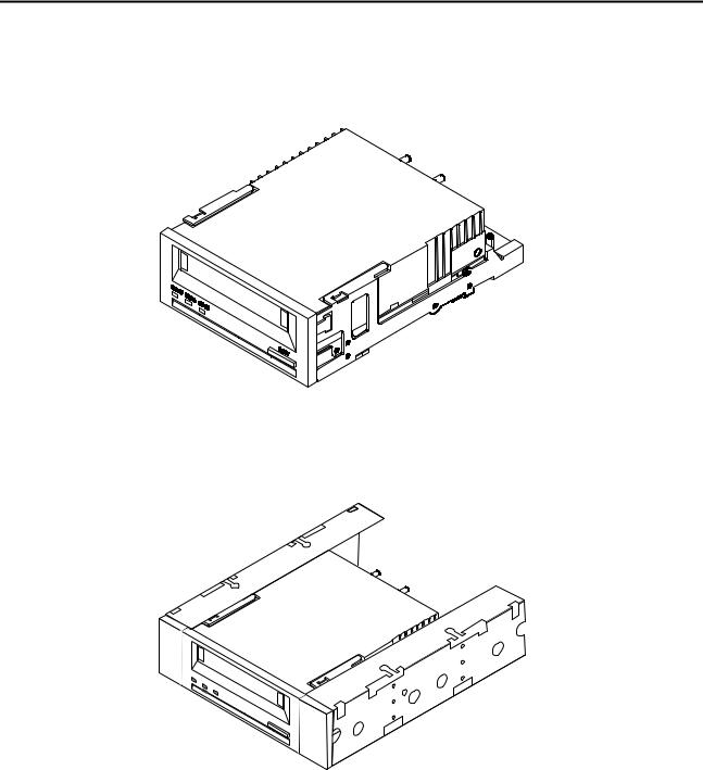
∙A 5.25-inch, half-height drive that consists of a 3.5-inch drive with 5.25-inch mounting rails and bezel that mounts internally in a 5.25-inch, half-height space (see Figure 2)
Figure 2. Internal Drive with Drive Rails for Mounting in a 5.25-inch Drive Bay
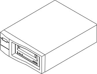
∙A complete external subsystem that contains the 3.5-inch drive and built-in worldwide power supply (see Figure 3)
Introduction |
5 |
Figure 3. External Drive
6 |
DAT 72/DDS-4 Product Manual |

Specifications |
7 |
Specifications |
2 |
|
|
|
|
|
|
Overview
This chapter includes technical specifications for the internal and external SCSI drives. This information covers the following specifications and requirements:
∙Physical specifications
∙Power specifications
∙Drive performance specifications
∙Environmental requirements
∙Reliability
∙DDS cartridge specifications
∙Regulatory compliance
Physical Specifications
The physical specifications of the internal and external DAT 72 and DDS-4 models are listed in the following table:
Specification |
Internal |
Internal with rails |
External |
Height |
1.6 in/41.2 mm |
1.6 in/41.2 mm |
2.7 in/69 mm |
Width |
4.0 in/101.6 mm |
5.74 in/146.0 mm |
6.1 in/152.0 mm |
Length |
5.7 in/146.0 mm |
6.9 in/175.0 mm |
9.3 in/235.0 mm |
Weight |
1.4 lb/0.62 kg |
1.8 lb/0.87 kg |
4.1 lb/1.8 kg |
Figures 4 and 5 on the following pages show the dimensions of the internal 3.5-inch and 5.25-inch drives.

8 |
DAT 72/DDS-4 Product Manual |
41.3 mm |
101.6 mm |
(1.63 in) |
(4.00 in) |
13.0 mm (0.51 in) |
|
2 places |
3.8 mm (0.15 in) |
5.0 mm (0.196 in) |
94.0 mm |
2 places |
(3.70 in) |
|
|
M3.0 x 4 deep min. |
|
(10 places) |
|
|
M3.0 x 4 deep min. |
90.0 mm |
(4 places) |
|
|
(3.54 in) |
|
2 places |
|
60.0 mm |
|
(2.36 in) |
|
2 places |
|
21.0 mm (0.83 in) |
|
2 places |
|
146.0 mm
(5.75 in)
70.0 mm
(2.75 in)
31.0 mm
(1.22 in)
41.2 mm |
6.0 mm |
|
|
|
|
101.6 mm |
||||
|
|
|
|
|||||||
|
|
|
||||||||
|
(1.62 in) |
|
|
(0.24 in) |
|
|
(4.00 in) |
|
||
Side View |
|
|
|
|
Bottom View |
|||||
Note: Tolerance for all dimensions is 0.25mm (0.01 in)
Figure 4. Internal Drive— Dimensions
|
|
|
|
41.3 mm |
|
|
|
|
|
|
|||||||||
|
|
|
|
(1.63 in) |
|
|
|
|
|
31.5 mm (1.24 in) |
|
|
|
||||||
|
|
|
|
|
|
|
|
|
|
|
|
|
|
|
|
|
|
||
|
|
|
|
|
|
|
|
|
|
|
|
|
|
|
|
|
|
||
|
|
|
|
|
|
|
|
|
|
|
|
|
|
|
21.8 mm (0.86 in) |
|
|
146 mm |
|
|
|
|
|
|
|
|
|
|
|
|
|
|
|
|
|
|
|||
|
|
|
|
|
|
|
|
|
|
|
|
|
|
|
9.9 mm (0.39 in) |
|
|
||
|
|
|
|
|
|
|
|
|
|
|
|
|
|
|
|
|
|
|
(5.75 in) |
|
|
|
|
|
|
|
|
|
|
|
|
|
|
|
|
|
|
|
|
16-M3 |
|
|
174.6 mm |
79.4 mm |
|
(6.87 in) |
(3.13 in) |
|
|
47.6 mm |
|
|
(1.87 in) |
|
41.2 mm |
139.7 mm (5.50 in) |
|
(1.62 in) |
||
|
||
|
149.1 mm (5.87 in) |
Side View |
Note: Tolerance for all dimensions is 0.25mm (0.01 in) |
|
Bottom View
Figure 5. Internal DDS Drive with Rails— Dimensions

Specifications |
9 |
Power Specifications
The following table lists the power specifications for the internal DAT 72 and DDS-4 drives.
Specification |
+12 VDC supply |
+5 VDC supply |
Voltage Tolerance |
+ or – 10% operating |
Operational Current |
250 milliamps max |
Standby Current |
15 milliamps max |
Surge (peak) |
600 milliamps max |
Ripple (peak-to-peak) |
≤ 100 mV (peak to peak) |
+ or – 7% operating 1.35 Amps max 1.2 Amps max
1.5 Amps max
≤ 100 mV (peak to peak)
Total power consumption for the DAT 72 is as follows:
Standby Power |
6.5 watts max |
Operating Power |
8.7 watts typical, 10.0 watts max |
Surge (start up) |
20.0 watts max (instantaneous peak) |
Note: When measured over a 20-msec period, the maximum surge power is 14.0 watts.
Total power consumption for the DDS-4 (including both the +5V and +12V power supplies) is as follows:
Standby Power |
6.0 watts max |
Operating Power |
9.0 watts typical, 10.0 watts max |
Surge (start up) |
14.0 watts max |
Note: Surge power and current are measured over a 20-msec period.
The following table lists pin assignments of the power connector for the internal DDS.
Pin |
Assignment |
1 |
+12 VDC |
2 |
+12 return |
3 |
+5 return |
4 |
+5 VDC |
The external drives have a built-in power supply that senses the incoming voltage and automatically adapts to voltages within the range of 100 to 240 volts, 50 to 60 Hz. The following table lists the power specifications of the power supply.
Specification |
|
AC Input Voltage |
|
|
|
|
|
|
100 (Japan) |
120 (US) |
240 (European) |
AC Input Current |
100 milliamps |
85 milliamps |
170 milliamps |
AC Input Power |
10.0 watts |
10.0 watts |
10.0 watts |
|
|
|
|
Note: The drive employs a power-sensing circuit that automatically detects a loss of supply voltage from the host. Temporary loss of supply voltage, or voltage spikes, might result in the drive electronics being reset to their initialized state, but shall under no circumstances result in a loss of recorded data.

10 |
DAT 72/DDS-4 Product Manual |
Drive Performance Specifications
The following table lists the specifications for the DAT 72 drive.
Specification
Capacity
125 m MP++
150 m MP+++
170 m MP++++
Error recovery
Track density (DAT 72)
Recording unrecoverable errors
Tape drive type
Head configuration
Recording format
Recording method
Cartridge
Transfer rate (sustained)
Synchronous transfer rate (burst)
Asynchronous transfer rate (burst)
Search speed (max)
Average access time 125 m cartridge 150 m cartridge 170 m cartridge
Drum rotation speed
Tape speed
Head-to-tape speed
Value
24.0 Gbytes
40.0 Gbytes
72.0 Gbytes Read-after-write (RAW)
Reed Solomon ECC (C3 - 3 levels) 4704 tracks per inch (TPI)
<1 in 1015 data bits
Computer-grade 4DD mechanism
2 read heads, 2 write heads
DDS 5th Generation
Helical scan
73.66 mm × 53.34 mm × 10.16 mm
7.700 Kbytes per sec (DC ON)
80 Mbytes per sec max
10 Mbytes per sec max
200x normal (3260 mm per sec)
<30 seconds
<30 seconds
<40 seconds
10,000 Revolutions per Minute (RPMs)
2 meters per second
15.75 mm/second
 Loading...