


|
|
×óÀº³?³ |
|
|
|
Hi-bit Legato Link Conversion |
|
|
POWER |
|
|
|
|
ë |
|
|
|
Ñ OFF _ ON |
|
|
|
|
|
|
|
|
|
|
|
|
|
0 OPEN/CLOSE |
|
|
|
PHONES LEVEL |
|
|
|
|
|
|
|
|
|
|
|
|
|
|
|
4 |
¢ |
MIN MAX |
|
Ö COMPU |
|
OFF |
' |
1 |
Á |
|
|
Ö AUTOÖ |
|
|
|
|
|
||
PHONES |
|
|
DIGITAL |
|
8 |
7 |
|
|
|
REPEAT |
EDIT |
OUTPUT |
DISPLAY |
3 |
|
||
ë
|
|
– |
+ |
OUTPUT LEVEL |
|
|
|
1 |
2 |
3 |
4 |
5 |
6 |
7 |
8 |
9 |
10 |
11 |
12 |
13 |
14 |
15 |
16 |
17 |
18 |
19 |
20 |
HI-LITE |
|
PROGRAM |
> 20 |
RANDOM |
7 |
8 |
3 |
1 |
Á |
4 |
¢ |
COMPACT DISC PLAYER
REMOTE CONTROL UNIT ' CU-P0092
ORDER NO.
RRV1981
COMPACT DISC PLAYER
PD-S707
THIS MANUAL IS APPLICABLE TO THE FOLLOWING MODEL(S) AND TYPE(S).
Type |
Model |
Power Requirement |
The voltage can be converted by the following method. |
||||
|
|||||||
PD-S707 |
|||||||
|
|
|
|
|
|
||
|
|
|
|
|
|
|
|
MY |
à |
AC220–230V |
|
|
|
|
|
|
|
|
|
||||
|
|
|
|
|
|
|
|
MV |
à |
AC220–230V |
|
|
|
|
|
|
|
|
|
||||
|
|
|
|
|
|
|
|
SD |
à |
AC110V/120-127V/220-230V/240V |
With the voltage selector |
||||
|
|
|
|
|
|
|
|
HPW |
à |
AC230– 240V |
|
|
|
|
|
|
|
|
|
||||
|
|
|
|
|
|
|
|
CONTENTS
1. SAFETY INFORMATION .................................... |
2 |
7. GENERAL INFORMATION .............................. |
38 |
|
2. EXPLODED VIEWS AND PARTS LIST ............. |
3 |
7.1 |
IC ................................................................ |
38 |
3. SCHEMATIC DIAGRAM ................................... |
12 |
7.2 |
DISPLAY .................................................... |
39 |
4. PCB CONNECTION DIAGRAM ....................... |
19 |
7.3 |
BLOCK DIAGRAM ..................................... |
40 |
5. PCB PARTS LIST ............................................. |
26 |
8. PANEL FACILITIES AND SPECIFICATIONS |
|
|
6. ADJUSTMENT .................................................. |
30 |
|
................................................................... |
41 |
PIONEER ELECTRONIC CORPORATION 4-1, Meguro 1-Chome, Meguro-ku, Tokyo 153-8654, Japan PIONEER ELECTRONICS SERVICE, INC. P.O. Box 1760, Long Beach, CA 90801-1760, U.S.A.
PIONEER ELECTRONIC (EUROPE) N.V. Haven 1087, Keetberglaan 1, 9120 Melsele, Belgium
PIONEER ELECTRONICS ASIACENTRE PTE. LTD. 501 Orchard Road, #10-00 Wheelock Place, Singapore 238880
 PIONEER ELECTRONIC CORPORATION 1998
T–ZZR JULY 1998 Printed in Japan
PD-S707
1. SAFETY INFORMATION
IMPORTANT
THIS PIONEER APPARATUS CONTAINS
LASER OF CLASS 1.
SERVICING OPERATION OF THE APPARATUS
S H O U L D B E D O N E B Y A S P E C I A L L Y
INSTRUTED PERSON.
LASER DIODE CHARACTERISTICS
MAXIMUM OUTPUT POWER: 5 mw
WAVELENGTH: 780 – 785 nm
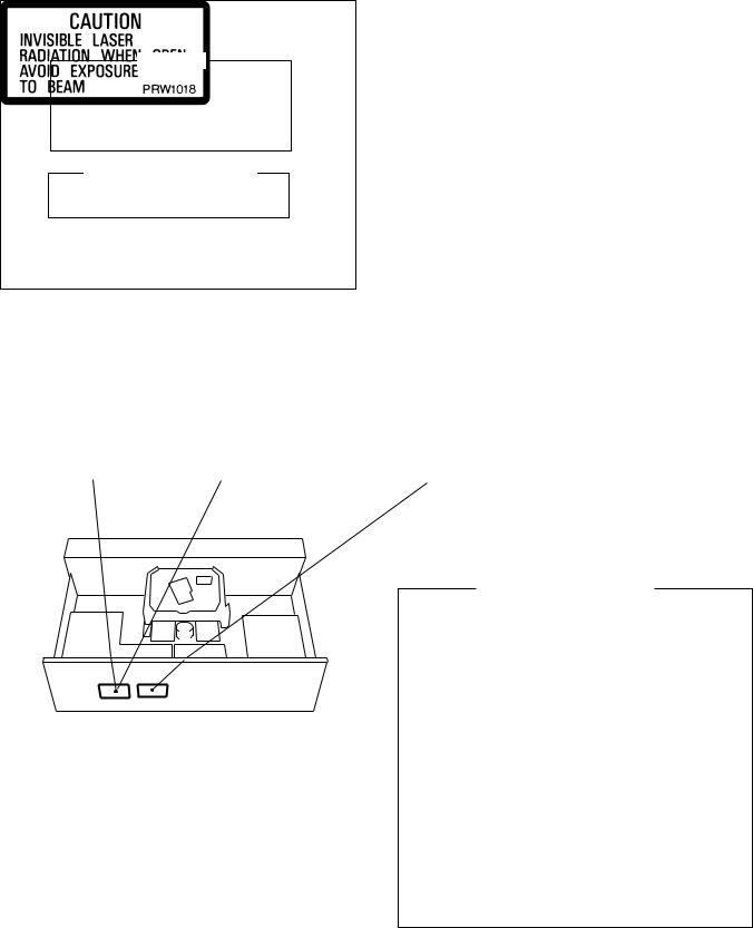
LABEL CHECK
MV and HPW types
MY type
REAR
MY type
Additional Laser Caution
1.Laser Interlock Mechanism
The position of the switch (S601) for detecting loading state is detected by the system microprocessor, and the design prevents laser diode oscillation when the switch (S601) is not on CLMP terminal side (CLMP signal is OFF or high level.). Thus, the interlock will no longer function if the switch (S601) is deliberately set to CLMP terminal
side (low level).
The interlock also does not function in the test mode . Laser diode oscillation will continue, if pin 33 of CXA1782CQ (IC151) on the MAIN BOARD ASSY is connected to GND, or pin 22 of IC301(LDON) is connected to low level (ON), or else the terminals of Q151 are shorted to each other (fault condition).
2.When the cover is opened with the servo mechanism block removed and turned over, close viewing of the objective lens with the naked eye will cause exposure to a Class 1 laser beam.
Refer to page 31 .
2
PD-S707
2. EXPLODED VIEWS AND PARTS LIST
NOTES : Ö Parts marked by “ NSP ” are generally unavailable because they are not in our Master Spare Parts List.
ÖThe  mark found on some component parts indicates the importance of the safety factor of the part. Therefore, when replacing, be sure to use parts of identical designation.
ÖScrew adjacent to °mark on the product are used for disassembly.
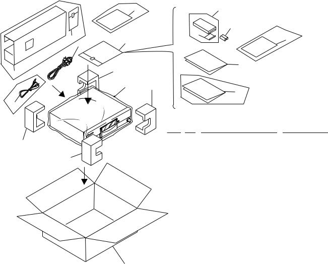
2.1PACKING
|
type |
Only |
MV |
|
|
|
|
16
5
13 |
6 |
SD type Only |
9 |
|
7 |
10
11
|
|
|
|
|
Except SD type |
|
2 (2/2) |
|
|
15 |
|
12 |
|
|
|
|
|
|
|
|
|
|
|
HPW type Only |
4 |
1 (2/2) |
|
MY and SD types Only |
|
|
8 |
|
|||
|
|
|
|
|
|
14 |
|
|
|
|
|
|
|
(1)PACKING PARTS LIST |
|
||
|
|
Mark |
No. |
Description |
Parts No. |
2 (1/2) |
|
|
1 |
Styrol Protector (F) |
PHA1319 |
|
|
2 |
Styrol Protector (R) |
PHA1320 |
|
|
|
|
|||
|
|
|
3 |
Packing Case |
See Contrast table(2) |
|
1 (1/2) |
|
4 |
Seat (750 × 600 × 0.5) |
Z23–007 |
|
|
|
5 |
Output Cable (L=1.2 m) |
PDE1248 |
|
|
|
6 |
Remote Control Unit |
PWW1143 |
|
|
|
|
(CU-PD097) |
|
|
|
|
7 |
Battery Cover |
PZN1103 |
|
|
|
8 |
Operating Instructions |
See Contrast table(2) |
|
|
NSP |
9 |
Dry Cell Battery (R03, AAA) |
VEM–022 |
|
|
|
10 |
Polyethylene Bag |
Z21–038 |
|
|
|
|
(0.03 × 230 × 340) |
|
(2) CONTRAST TABLE
NSP |
11 |
Warranty Card |
See Contrast table(2) |
|
|
12 |
V Spacer |
See Contrast table(2) |
|
NSP |
13 |
Caution 220V Card |
See Contrast table(2) |
|
|
14 |
Control Cable (for SR) (L=1m) |
See Contrast table(2) |
|
|
15 |
Operating Instructions |
PRE1268 |
|
3 |
|
(English/ French/ German/Spanish) |
||
16 |
Polyethylene Bag |
See Contrast table(2) |
||
|
||||
PD-S707/MY, MV, SD and HPW are constructed the same except for the following:
Mark |
No. |
Symbol and Description |
|
Part No. |
|
|
Remarks |
|
|
|
|
|
|
||||
MY type |
MV type |
|
SD type |
HPW type |
||||
|
|
|
|
|
||||
|
|
|
|
|
|
|
|
|
|
3 |
Packing Case S707 |
PHG2321 |
PHG2328 |
|
PHG2327 |
PHG2327 |
|
|
8 |
Operating Instructions |
PRD1032 |
Not used |
|
Not used |
Not used |
|
|
|
(Italian/Dutch/ Swedish/ Portouguese) |
|
|
|
|
|
|
|
8 |
Operating Instructions (Chinese) |
Not used |
Not used |
|
PRD1030 |
Not used |
|
NSP |
11 |
Warranty Card |
ARY7022 |
ARY7008 |
|
Not used |
ARY7022 |
|
|
12 |
V Spacer |
Not used |
PHC1089 |
|
Not used |
Not used |
|
NSP |
13 |
Caution 220V Card |
Not used |
Not used |
|
ARR7003 |
Not used |
|
|
14 |
Control Cable |
Not used |
Not used |
|
Not used |
PDE1247 |
|
|
16 |
Polyethylene Bag |
Not used |
Z21013 |
|
Not used |
Not used |
|
3

PD-S707
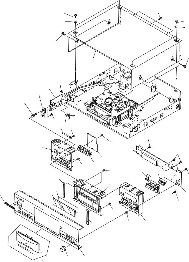
2.2 EXTERIOR (1/2)
18
13
23
18
12
Refer to " 2.4 LOADING
MECHANISM ASSY TT96".
20
18
24
20 |
18 |
10
24 
 Refer to " 2.3 EXTERIOR (2/2)".
20
20
 2
2 
11
1
22 
22
|
SD type Only |
|
26 |
|
|
||
|
|
19 |
Fuse Holder 5 |
||||
|
25 |
|
|||||
18 |
18 |
|
MV type Only |
|
|
||
|
|
MV and HPW types Only |
|||||
18 |
24 |
|
|
|
|
|
|
|
|
5 |
14 |
|
|
|
|
|
|
Except MV |
|
|
|
|
|
|
4 |
type |
MY |
type |
|
||
|
|
15 |
|
Only |
|||
|
|
|
|
|
|
||
2 |
|
17 |
|
|
|
|
|
18 |
|
|
|
|
|
||
|
|
|
|
|
|
||
|
|
|
|
|
16 |
||
|
6 |
|
|
|
|
||
|
17 |
|
|
|
|
|
|
17 |
18 |
|
|
|
|
|
|
18 |
17 |
|
|
|
|
19 |
|
18 |
|
|
|
|
|||
|
|
|
|
|
|
|
|
18 |
18 |
|
|
|
|
|
|
|
|
|
|
|
|
|
|
|
18 |
17 |
|
|
|
|
|
3 |
|
|
|
|
|
|
|
18
18
18
24
18
 24
24


18
7
18
18
8
 18
18
1
10
20
9
11
22 |
22 |
4

PD-S707
(1) EXTERIOR (1/2) PARTS LIST
Mark |
No. |
|
Description |
Parts No. |
|||
|
|
|
|
|
|
|
|
|
|
|
|
|
|
|
|
|
|
1 |
|
MAIN BOARD ASSY |
See Contrast table(2) |
||
NSP |
2 |
|
PRIMARY SWITCH ASSY |
See Contrast table(2) |
|||
|
|
3 |
|
POWER BOARD ASSY |
See Contrast table(2) |
||
|
|
4 |
|
Strain Relief |
CM-22B |
||
|
|
5 |
|
AC Power Cord |
See Contrast table(2) |
||
|
|
6 |
|
Power Transformer |
See Contrast table(2) |
||
NSP |
7 |
|
Under Base |
PNA2446 |
|||
|
|
8 |
|
Rear Base S707 |
See Contrast table(2) |
||
NSP |
9 |
|
Bottom Plate |
PNA2376 |
|||
NSP |
10 |
|
Side Angle |
PNB1583 |
|||
|
|
11 |
|
Insulator Assy |
VXA2356 |
||
NSP |
12 |
|
Loading Mechanism Assy TT96 |
PXA1611 |
|||
|
|
13 |
|
Power Knob |
PAC1897 |
||
|
|
14 |
|
Caution Label |
See Contrast table(2) |
||
|
|
15 |
|
Caution Label |
See Contrast table(2) |
||
NSP |
16 |
|
Caution Label (HE) |
See Contrast table(2) |
|||
|
|
17 |
|
Screw (3×6) |
ABA1207 |
||
|
|
18 |
|
Screw |
ABA1011 |
||
|
|
19 |
|
Screw |
BBZ30P080FZK |
||
|
|
20 |
|
Screw |
BBT30P080FCC |
||
|
|
21 ............. |
|
|
|
||
|
|
22 |
|
Screw |
IBZ30P100FCC |
||
|
|
23 |
|
Binder |
ZCA-SKB90BK |
||
|
|
24 |
|
Cord Clamper |
RNH–184 |
||
|
|
25 |
|
Voltage Selector |
See Contrast table(2) |
||
|
|
26 |
|
Fuse (T5A) |
See Contrast table(2) |
||
(2) CONTRAST TABLE
PD-S707/MY, MV, SD and HPW are constructed the same except for the following:
Mark |
No. |
Symbol and Description |
|
Part No. |
|
Remarks |
||
|
|
|
|
|||||
MY type |
MV type |
SD type |
HPW type |
|||||
|
|
|
|
|||||
|
|
|
|
|
|
|
|
|
|
1 |
MAIN BOARD ASSY |
PWZ3793 |
PWZ3794 |
PWZ3795 |
PWZ3796 |
|
|
NSP |
2 |
PRIMARY SWITCH ASSY |
PWZ3869 |
PWZ3869 |
PWZ3870 |
PWZ3869 |
|
|
|
3 |
POWER BOARD ASSY |
PWZ3800 |
PWZ3801 |
PWZ3802 |
PWZ3803 |
|
|
|
5 |
AC Power Cord |
PDG1003 |
PDG1055 |
PDG1013 |
ADG1123 |
|
|
|
6 |
Power Transformer |
PTT1301 |
PTT1301 |
PTT1302 |
PTT1301 |
|
|
|
8 |
Rear Base S707 |
PNA2433 |
PNA2447 |
PNA2448 |
PNA2449 |
|
|
|
14 |
Caution Label |
Not used |
PRW1018 |
Not used |
PRW1018 |
|
|
|
15 |
Caution Label |
VRW1094 |
Not used |
Not used |
Not used |
|
|
NSP |
16 |
Caution Label (HE) |
VRW1297 |
Not used |
Not used |
Not used |
|
|
|
25 |
Voltage Selector |
Not used |
Not used |
AKX7001 |
Not used |
|
|
|
26 |
Fuse (T5A)(For AC Power Cord) |
Not used |
PEK1003 |
Not used |
Not used |
|
|
|
|
|
|
|
|
|
|
|
5
PD-S707
2.3 EXTERIOR (2/2)
28 |
34 |
|
|
20 |
28 |
|
20 |
28
28
27
31
3
4
9
30
36 32
|
30 |
|
|
|
30 |
|
30 |
|
|
16 |
|
|
|
30 |
|
2 |
|
|
5 |
|
|
14 |
|
|
35 |
6 |
|
|
7 |
|
13 |
30 |
|
|
|
|
15 |
|
|
11 |
|
18 |
10 |
1 |
|
|
30 |
|
35 |
|
13 |
29 |
17 |
|
||
|
|
26 25
8 12
24
6
PD-S707
(1) EXTERIOR (2/2) PARTS LIST
Mark |
No. |
|
Description |
|
Parts No. |
Mark No. |
|
Description |
|
Parts No. |
||||
|
|
|
|
|
|
|
|
|
|
|
|
|
|
|
|
|
|
|
|
|
|
|
|
|
|
|
|
|
|
|
|
1 |
|
DISPLAY BOARD ASSY |
|
See Contrast table(2) |
31 |
|
Screw |
|
IBZ30P060FMC |
|||
NSP |
2 |
|
FUNCTION BOARD ASSY |
|
PWZ3812 |
32 |
|
Connector Assy 4P |
|
PDE1294 |
||||
NSP |
3 |
|
PHONE BOARD ASSY |
|
See Contrast table(2) |
33 |
|
……………… |
|
|
||||
|
|
4 |
|
H.P. Angle |
|
PNB1582 |
34 |
|
Screw |
|
BBZ30P080FZK |
|||
|
|
5 |
|
Mode Button S707 |
|
PAC1895 |
35 |
|
Screw |
|
BPZ20P060FMC |
|||
|
|
6 |
|
Play Button |
|
RAC2204 |
36 |
|
Cord Clamper |
|
RNH–184 |
|||
|
|
7 |
|
Manual Button |
|
PAC1894 |
|
|
|
|
|
|
|
|
|
|
8 |
|
Track Knob S707 |
|
PAC1898 |
|
|
|
|
|
|
|
|
|
|
9 |
|
Headphone Knob |
|
PAC1707 |
|
|
|
|
|
|
|
|
|
|
10 |
|
Display Window |
|
PAM1766 |
|
|
|
|
|
|
|
|
|
|
11 |
|
FL Sheet |
|
See Contrast table(2) |
|
|
|
|
|
|
|
|
|
|
12 |
|
Front Panel S707 |
|
PAN1370 |
|
|
|
|
|
|
|
|
|
|
13 |
|
Side Sash |
|
PAP1004 |
|
|
|
|
|
|
|
|
|
|
14 |
|
LED Lens |
|
PNW2745 |
|
|
|
|
|
|
|
|
|
|
15 |
|
Panel CDB |
|
PNW2810 |
|
|
|
|
|
|
|
|
|
|
16 |
|
Panel LB |
|
PNW2811 |
|
|
|
|
|
|
|
|
|
|
17 |
|
Panel RB |
|
PNW2812 |
|
|
|
|
|
|
|
|
|
|
18 |
|
Name Plate |
|
PAN1376 |
|
|
|
|
|
|
|
|
|
|
19 |
|
……………… |
|
|
|
|
|
|
|
|
|
|
|
|
20 |
|
Washer |
|
ABE1009 |
|
|
|
|
|
|
|
|
21………………
22………………
23.....................
|
24 |
Tray Plate Assy S707 |
PEA1348 |
NSP |
25 |
Tray Panel B |
PNW2814 |
NSP |
26 |
Tray Badge |
PAN1358 |
|
27 |
Bonnet Case |
PYY1257 |
|
28 |
Screw |
BBZ40P080FZK |
|
29 |
Nut |
NK90FUC |
|
30 |
Screw |
PPZ30P080FMC |
(2) CONTRAST TABLE
PD-S707/MY, MV, SD and HPW are constructed the same except for the following:
Mark |
No. |
Symbol and Description |
|
Part No. |
|
Remarks |
||
|
|
|
|
|||||
MY type |
MV type |
SD type |
HPW type |
|||||
|
|
|
|
|||||
|
|
|
|
|
|
|
|
|
|
1 |
DISPLAY BOARD ASSY |
PWZ3807 |
PWZ3807 |
PWZ3807 |
PWZ3808 |
|
|
NSP |
3 |
PHONE BOARD ASSY |
PWZ3815 |
PWZ3815 |
PWZ3816 |
PWZ3816 |
|
|
|
11 |
FL Sheet S707 |
PAM1737 |
PAM1737 |
PAM1763 |
PAM1763 |
|
|
|
|
|
|
|
|
|
|
|
7
PD-S707
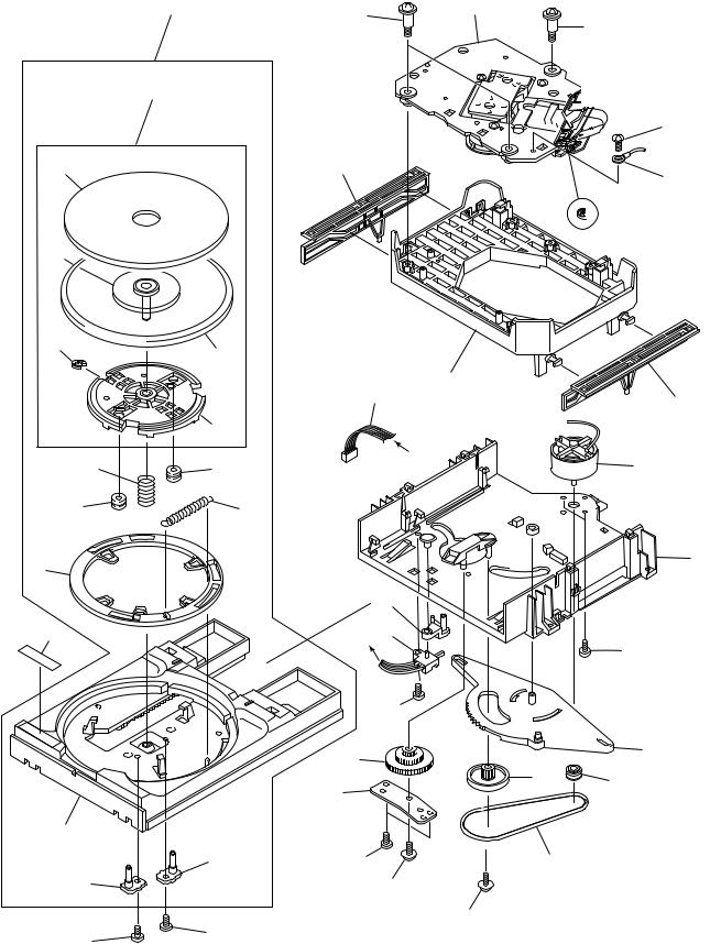
2.4 LOADING MECHANISM ASSY TT96
15
35
28
12
14
18
33
16
17
21
36
23
26
25
14
13
17
21
 27 2
27 2
2
Refer to " 2.5 SERVO
MECHANISM ASSY T96".
31
10
32
Spacer
9
34
11
A 

A
19
24
8
A 1
20
30

 6 5
6 5 

7 |
4 |
|
29
30 |
3 |
22
22
8
PD-S707
LOADING MECHANISM ASSY TT96 PARTS LIST
Mark No. |
|
Description |
|
Parts No. |
|
Mark |
No. |
|
Description |
|
Parts No. |
|||
|
|
|
|
|
|
|
|
|
|
|
|
|
|
|
|
|
|
|
|
|
|
|
|
|
|
|
|
|
|
1 |
|
Lever Switch (S601) |
|
DSK1003 |
|
|
|
26 |
|
Turn Table |
|
PNR1035 |
||
2 |
|
Float Screw |
|
PBA1027 |
|
NSP |
27 |
|
Servo Mechanism Assy T96 |
|
PXA1606 |
|||
3 |
|
Rubber Belt |
|
PEB1186 |
|
|
|
28 |
|
E Ring |
|
YE20FUC |
||
4 |
|
Motor Pulley |
|
PNW1634 |
|
|
|
29 |
|
Shaft Holder |
|
PNB1382 |
||
5 |
|
Drive Gear |
|
PNW1996 |
|
|
|
30 |
|
Screw |
|
BPZ26P060FMC |
||
6 |
|
Synchronized Lever |
|
PNW2168 |
|
|
|
31 |
|
Screw |
|
BBZ26P060FMC |
||
7 |
|
Gear Pulley |
|
PNW1998 |
|
NSP |
32 |
|
Earth Lead |
|
DE010VF0 |
|||
8 |
|
SW Head |
|
PNW1999 |
|
|
|
33 |
|
Caution Label |
|
PRW1244 |
||
9 |
|
Float Base |
|
PNW2767 |
|
|
|
34 |
|
Connector Assy 5P |
|
PDE1243 |
||
10 |
|
Left Cam |
|
PNW2001 |
|
NSP |
35 |
|
Table Base |
|
PXA1382 |
|||
11 |
|
Right Cam |
|
PNW2002 |
|
NSP |
36 |
|
Tray Assy TT |
|
PXA1397 |
|||
12 |
|
Float Spring |
|
PBH1120 |
|
|
|
|
|
|
|
|
||
13 |
|
Lock Spring |
|
PBH1121 |
|
|
|
|
|
|
|
|
||
14 |
|
Float Rubber |
|
PEB1014 |
|
|
|
|
|
|
|
|
||
15 |
|
Table Rubber Sheet |
|
PEB1181 |
|
|
|
|
|
|
|
|
||
16 |
|
Tray |
|
PNW2760 |
|
|
|
|
|
|
|
|
||
17 |
|
Table Guide |
|
PNW2004 |
|
|
|
|
|
|
|
|
||
18 |
|
Lock Plate |
|
PNW2005 |
|
|
|
|
|
|
|
|
||
19 |
|
D.C. Motor (0.75W, LOADING) |
|
PXM1010 |
|
|
|
|
|
|
|
|
||
20 |
|
Screw |
|
BMZ26P040FMC |
|
|
|
|
|
|
|
|
||
21 |
|
Screw |
|
IPZ26P060FCU |
|
|
|
|
|
|
|
|
||
22 |
|
Screw |
|
IPZ20P080FMC |
|
|
|
|
|
|
|
|
||
23 |
|
Turn Table Assy |
|
PEA1165 |
|
|
|
|
|
|
|
|
||
24 |
|
Loading Base |
|
PNW2761 |
|
|
|
|
|
|
|
|
||
25 |
|
Table Shaft Holder Assy |
|
PXA1383 |
|
|
|
|
|
|
|
|
||
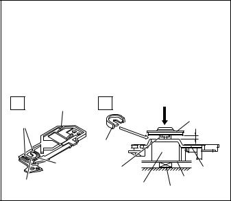
¦ How to Install the Disc Table
1 Use nipper or other tool to cut the three sections marked A in figure 1. Then remove the spacer
2 While supporting the spindle motor shaft with the stopper, put spacer on top of the carriage base, and stick the disc table on top (takes about 9kg pressure). Take off the spacer.
1 |
FFC Holder |
2 |
(Pressure of about 9kg) |
|
|
|
|||
|
|
|
|
Disc table |
A |
|
|
|
|
|
|
Spacer |
|
2.1mm |
|
|
|
|
|
|
A |
Spacer setting |
|
|
|
|
Carriage |
||
Spacer |
|
Position |
|
PCB Base |
Spindle motor Stopper
9
PD-S707
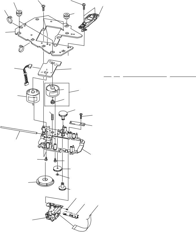
2.5 SERVO MECHANISM ASSY T96
21 |
18 |
18 |
|
23
20
22
17
20 
24 |
19 |
SERVO MECHANISM PARTS LIST |
|
|
|
Mark No. Description |
Parts No. |
|
|
|
1 |
Carriage D.C. Motor (0.3W) |
PXM1027 |
|
|
|
2 |
Pinion Gear |
PNW2055 |
|
1 |
25 |
3 |
Spindle Motor Assy |
PEA1236 |
|
|
|
(SPINDLE, with Oil) |
|
|
3 |
|
|
|
|
|
2 |
|
4 |
Carriage Base |
PNW2699 |
|
|
|
||||
|
|
5 |
Disc Table |
PNW1067 |
|
|
|
|
|||
16 |
|
13 |
6 |
Screw |
JFZ20P030FNI |
|
|
7 |
Screw |
JFZ17P025FZK |
|
|
|
15 |
|||
|
|
8 |
Gear 3 |
PNW2054 |
|
|
|
|
9 |
Gear 2 |
PNW2053 |
|
|
14 |
10 |
Washer |
WT12D032D025 |
|
|
|
|
|
|
|
|
|
11 |
Pickup Assy |
PEA1335 |
|
|
|
12 |
Guide Bar |
PLA1094 |
12 |
|
|
13 |
Gear 1 |
PNW2052 |
|
|
14 |
Gear Stopper |
PNB1303 |
|
|
|
|
|||
|
|
|
15 |
Screw |
BPZ20P060FMC |
|
|
4 |
16 |
Earth Spring |
PBH1132 |
6 |
7 |
NSP |
17 |
Mechanism Base T.T.96 |
PNB1592 |
|
18 |
Screw |
BPZ26P100FMC |
||
|
|
||||
|
|
|
|||
|
8 |
|
19 |
Mechanism Board Assy |
PWX1192 |
|
|
20 |
Binder |
PEC–107 |
|
|
10 |
|
21 |
Float Rubber |
PEB1031 |
|
|
22 |
Float Rubber |
PEB1170 |
|
5 |
|
|
|||
|
|
23 |
FFC Holder |
PNW2734 |
|
|
|
|
|||
|
9 |
|
24 |
Connector Assy 4P |
PDE1238 |
|
26 |
|
25 |
Carriage Motor Assy |
PEA1246 |
|
|
|
(CARRIAGE) |
|
|
|
27 |
28 |
26 |
Rack Spring |
PBH1128 |
|
|
||||
|
|
|
27 |
Rack Holder |
PNW2056 |
|
|
|
28 |
F.F.C.(16P) |
PDD1185 |
11 |
|
|
|
|
|
10
PD-S707
11
|
1 |
|
2 |
|
3 |
|
|
|
|
|
PD-S707
|
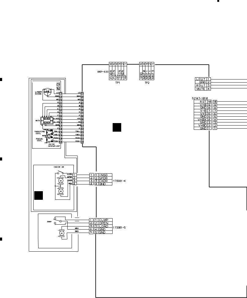
3. SCHEMATIC DIAGRAM |
|
A |
Note: When ordering service parts, be sure to refer to "EXPLODED VIEWS |
|
|
|
|
|
AND PARTS LIST" or "PCB PARTS LIST". |
|
|
3.1 OVERALL SCHEMATIC DIAGRAM |
|
|
LOADING MECHANISM |
CN201 |
|
ASSY TT 96 (PXA1611) |
|
PICK UP ASSY
PEA1335
CN131
SLW16S-IC7
B
A MAIN BOARD ASSY
(PWZ3793: MY)
(PWZ3794: MV)
(PWZ3795: SD) (PWZ3796: HPW)
SERVO MECHANISM
ASSY T96 (PXA1606)
DSG1016
SPINDLE
MOTOR
ASSY CN202
PEA1236
|
CARRIAGE |
CN610 |
|
|
MOTOR |
|
|
|
ASSY |
|
|
C |
G PEA1246 |
|
|
|
MECHANISM BOARD |
|
|
|
ASSY (PWX1192) |
|
|
|
S601:DSK1003 |
|
|
|
CLAMP SW |
|
CLMP |
OPEN |
CN204 |
LOAD |
PXM1010
LOADING MOTOR
D
12
4
CN403
KM250NA4L
CN11 
|
1 |
|
2 |
|
3 |
|
4 |
|
|
|
|
|
|
||||
|
|
|
|
|

|
5 |
|
6 |
|
7 |
|
|
|
CN404 |
|
WHT |
WHT |
KP250NA4L |
|
YEL |
YEL |
B |
POWER BOARD |
|
F |
ASSY (PWZ3800: MY) |
|
||
|
|
||
|
(PWZ3801: MV) |
|
PRIMARY SWITCH |
J11 |
(PWZ3802: SD) |
|
|
|
ASSY (PWZ3869:MY |
||
(PWZ3803: HPW) |
|
||
D20PDY1006G |
|
/MV/HPW) |
|
|
|
||
|
Power Transformer |
CN30 |
(PWZ3870:SD) |
|
52147-0410 |
|
|
|
(PTT1301: MY/MV/HPW) |
|
|
|
|
|
|
|
(PTT1302: SD) |
|
|
|
D20PDY0435G |
CN402 |
J501 |
B4B-PH-K-S |
|
PDE1294 |
CN501 |
CN22 |
B4B-PH-K-S |
|
E
PHONE BOARD
ASSY (PWZ3815:MY/MV) (PWZ3816:SD/HPW)
J703
D20PDY0640G
|
|
DISPLAY BOARD |
|
CN352 |
J702 |
C ASSY (PWZ3807:MY/MV/SD) |
|
(PWZ3808:HPW) |
|||
|
D20PDY0620B |
||
|
|
CN701
52151-0510
8
PD-S707
A
AC Power cord PDG1003: MY AC220-230V 50/60Hz PDG1055: MV AC220-230V 50Hz ADG1123: HPW AC230-240V 50/60Hz PDG1013: SD AC110V/120-127V/220- 230V/240V 50/60Hz
B
C
CN351 |
J701(:HPW) |
J704 (:MY/MV/SD) |
(:HPW) |
D20PDY1425G |
D20PDY1225G |
|
HPW |
|
CN351 |
|
ONLY |
|
J751 |
|
|
|
|
D20PDY0510E
(:MY/MV/SD)
D
D FUNCTION BOARD
ASSY (PWZ3812)
(:HPW)
(:MY/MV/SD)
13
|
5 |
|
6 |
|
7 |
|
8 |
|
|
|
|
|
|
||||
|
|
|
|
|
 Loading...