


MJ-D707
ORDER NO.
PIONEER ELECTRONIC CORPORATION 4-1, Meguro 1-Chome, Meguro-ku, Tokyo 153-8654, Japan
PIONEER ELECTRONICS SERVICE, INC. P.O. Box 1760, Long Beach, CA 90801-1760, U.S.A.
PIONEER ELECTRONIC (EUROPE) N.V . Haven 1087, Keetberglaan 1, 9120 Melsele, Belgium
PIONEER ELECTRONICS ASIACENTRE PTE. LTD. 501 Orchard Road, #10-00 Wheelock Place, Singapore 238880
PIONEER ELECTRONIC CORPORATION 1998
7. GENERAL INFORMATION .............................. 49
7.1 PARTS .......................................................49
7.1.1 IC .......................................................49
7.1.2 DISPLAY ...........................................60
7.2 DIAGNOSIS................................................61
7.2.1 DISASSEMBLY .................................61
7.2.2 DETAILS OF ERROR DISPLAY .......63
7.3 BLOCK DIAGRAM......................................65
8. PANEL FACILITIES AND SPECIFICATIONS
.......................................................66
MINIDISC RECORDER
RRV1963
MJ-D707
MJ-17D
1. SAFETY INFORMATION....................................2
2. EXPLODED VIEWS AND PARTS LIST .............4
3. SCHEMATIC DIAGRAM...................................12
4. PCB CONNECTION DIAGRAM ....................... 28
5. PCB PARTS LIST.............................................37
6. ADJUSTMENT..................................................41
CONTENTS
T–DZE JUNE 1998 Printed in Japan
KU AC120V
MY –– AC220–230V
MY/GR/FR –– AC220–230V
THIS MANUAL IS APPLICABLE TO THE FOLLOWING MODEL(S) AND TYPE(S).
Model
MJ-D707 MJ-17D
Type
Power Requirement
Remarks
MINIDISC RECORDER
MJ-D707
TIMER
REC
OFF
PLAY
DISC LOADING MECHANISM
PUSH ENTER
EDIT
/
NO
NAME
ANALOG
COAX
OPT
0
1
2
3
4
5
6
7
8
9
10
INPUT SELECTOR REC LEVEL
DIGITAL
NR
REPEAT
A B
TIME SKIP
PLAY
MODE
REC
MODE
NAME
CLIP
DISPLAY
/ CHARA
STANDBY
POWER
— OFF _ ON
SYNCHRO
REC
MIN
MAX
PHONES
LEVEL
)
EJECT
$
$
!
!
#
*
&
Î
Legato Link Conversion
MJ-D707, MJ-17D
2
1. SAFETY INFORMATION
1. SAFETY PRECAUTIONS
The following check should be performed for the
continued protection of the customer and service
technician.
ANY MEASUREMENTS NOT WITHIN THE LIMITS
OUTLINED ABOVE ARE INDICATIVE OF A PO-
TENTIAL SHOCK HAZARD AND MUST BE COR-
RECTED BEFORE RETURNING THE APPLIANCE
TO THE CUSTOMER.
2. PRODUCT SAFETY NOTICE
Many electrical and mechanical parts in the appli-
ance have special safety related characteristics. These
are often not evident from visual inspection nor the
protection afforded by them necessarily can be ob-
tained by using replacement components rated for
voltage, wattage , etc. Replacement parts which have
these special safety characteristics are identified in
this Service Manual.
Electrical components having such features are
identified by marking with a
on the schematics and
on the parts list in this Service Manual.
The use of a substitute replacement component which
does not have the same safety characteristics as the
PIONEER recommended replacement one, shown in
the parts list in this Service Manual, may create shock,
fire, or other hazards.
Product Safety is continuously under review and
new instructions are issued from time to time. For
the latest information, always consult the current
PIONEER Service Manual. A subscription to, or ad-
ditional copies of, PIONEER Service Manual may be
obtained at a nominal charge from PIONEER.
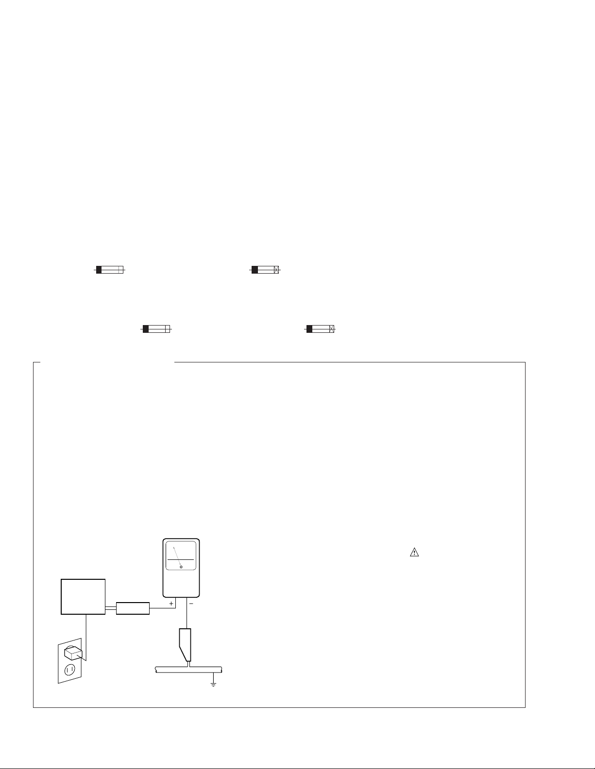
LEAKAGE CURRENT CHECK
Measure leakage current to a known earth ground
(water pipe, conduit, etc.) by connecting a leakage
current tester such as Simpson Model 229-2 or
equivalent between the earth ground and all exposed
metal parts of the appliance (input/output terminals,
screwheads, metal overlays, control shaft, etc.). Plug
the AC line cord of the appliance directly into a 120V
AC 60 Hz outlet and turn the AC power switch on. Any
current measured must not exceed 0.5 mA.
(FOR USA MODEL ONLY)
Also test with plug
reversed
(Using AC adapter
plug as required)
Device
under
test
Test all exposed
metal surfaces
Earth ground
Leakage
current
tester
Reading should
not be above
0.5 mA
AC Leakage Test
REMARQUE
(POUR MODÈLE CANADIEN SEULEMENT)
Les symboles de fusible (fusible de type rapide) et/ou (fusible de type lent) sur CCI indiquent que les
pièces de remplacement doivent avoir la même désignation.
NOTICE
(FOR CANADIAN MODEL ONLY)
Fuse symbols (fast operating fuse) and/or (slow operating fuse) on PCB indicate that replacement parts
must be of identical designation.
This service manual is intended for qualified service technicians; it is not meant for the casual
do-it-yourselfer. Qualified technicians have the necessary test equipment and tools, and have been
trained to properly and safely repair complex products such as those covered by this manual.
Improperly performed repairs can adversely affect the safety and reliability of the product and may
void the warranty. If you are not qualified to perform the repair of this product properly and safely, you
should not risk trying to do so and refer the repair to a qualified service technician.
WARNING
This product contains lead in solder and certain electrical parts contain chemicals which are known to the state of California to
cause cancer, birth defects or other reproductive harm.
Health & Safety Code Section 25249.6 – Proposition 65
MJ-D707, MJ-17D
3
IMPORTANT
THIS PIONEER APPARATUS CONTAINS
LASER OF CLASS 1.
SERVICING OPERATION OF THE APPARATUS
SHOULD BE DONE BY A SPECIALLY
INSTRUTED PERSON.
LASER DIODE CHARACTERISTICS
MAXIMUM OUTPUT POWER: 32 mw
WAVELENGTH: 785 nm
Laser pick-up assembly
The output power at the objective lens of this assembly is 0.73 mW.
Control method of the current through a laser diode.
The resistor R105 on the CORD MAIN UNIT ASSY (For MD
mechanism assembly) are for the limiting of current through a laser
diode.
Control method of the laser output power
The laser pick-up assembly provide the photo-diodes and APC
(Auto Power Control) circuit.
The photo-diode detect output of the laser diode then IC104 control
the APC circuit according to the signal voltage of the photo-diode via
IC101.
The Variable resistancer on the FPC in the Laser pick-up assembly
can be adjusted the output level of Laser diode to fix the rated output
level.
Laser Interlock Switch
The loading position detect switch S101 is set to “ LOAD ON ” (ON:
low level, OFF: high level) position, IC104 get the “ LOAD ” signal,
and hand the laser “ LDON ” signal to No. 9 terminal (LDON) of the
Laser pick-up assembly.
Then a laser diode can be lighted exept when the level of signal
“LOAD ” is low.
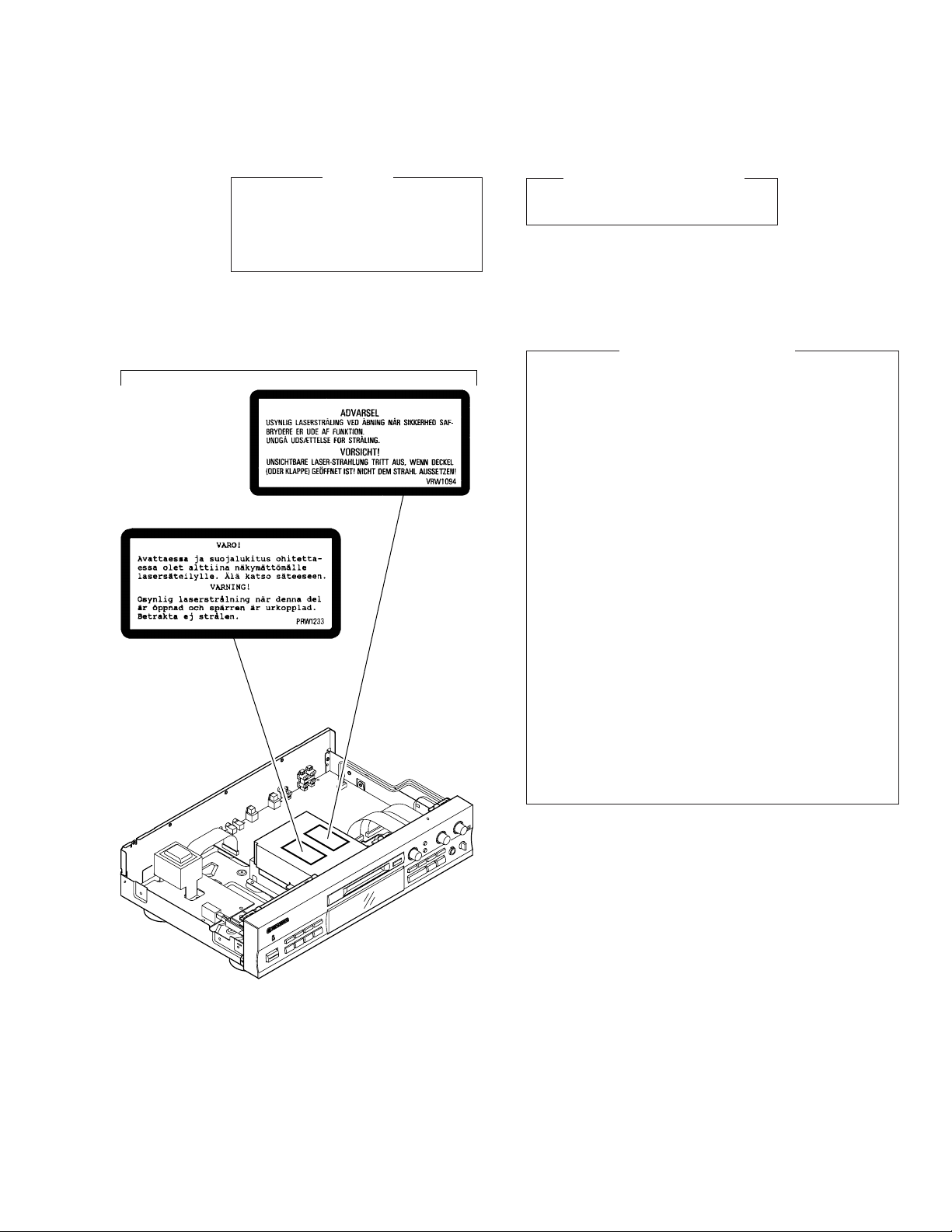
Additional Laser Caution
LABEL CHECK
MY and MY/GR/FR types
∗ Refer to page 42.
MJ-D707, MJ-17D
4
RANDOMHI-LITE MEDLEY FADER
REPEAT PGM CHECK CLEAR
DISP
/
CHARA
EDIT
/
NO
NAME
NAME
CLIP
TIME
SKIP
ENTERA B
SYNCHRO
REC
REC
CURSOR
1 2 3
4 5 6
7 8 9
10/0
>
10
&
*
#
!
!
$
$
Î
MINIDISC
RECORDER
REMOTE CONTROL UNIT
STANDBY/ ON
MARK
ABC DEF
GHI JKL MNO
PQRS TUV WXYZ
3
8
11 (MJ-D707/KU, MY only)
10
7
6
9
5
4
1 (1/2)
2 (1/2)
2 (2/2)
1 (2/2)
12 (MJ-D707/MY, MY/GR/FR only)
13 (MJ-D707/MY only)
14 (MJ-17D/KU only)
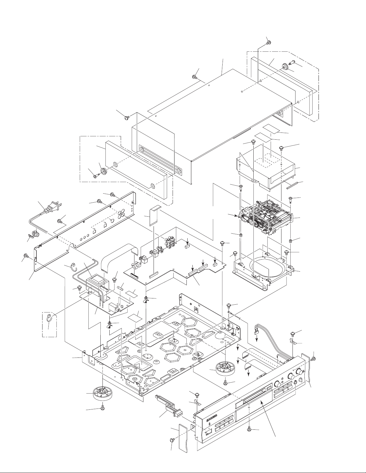
2. EXPLODED VIEWS AND PARTS LIST
NOTES : Parts marked by “ NSP ” are generally unavailable because they are not in our Master Spare Parts List.
The mark found on some component parts indicates the importance of the safety factor of the part.
Therefore, when replacing, be sure to use parts of identical designation.
Screw adjacent to mark on the product are used for disassembly.
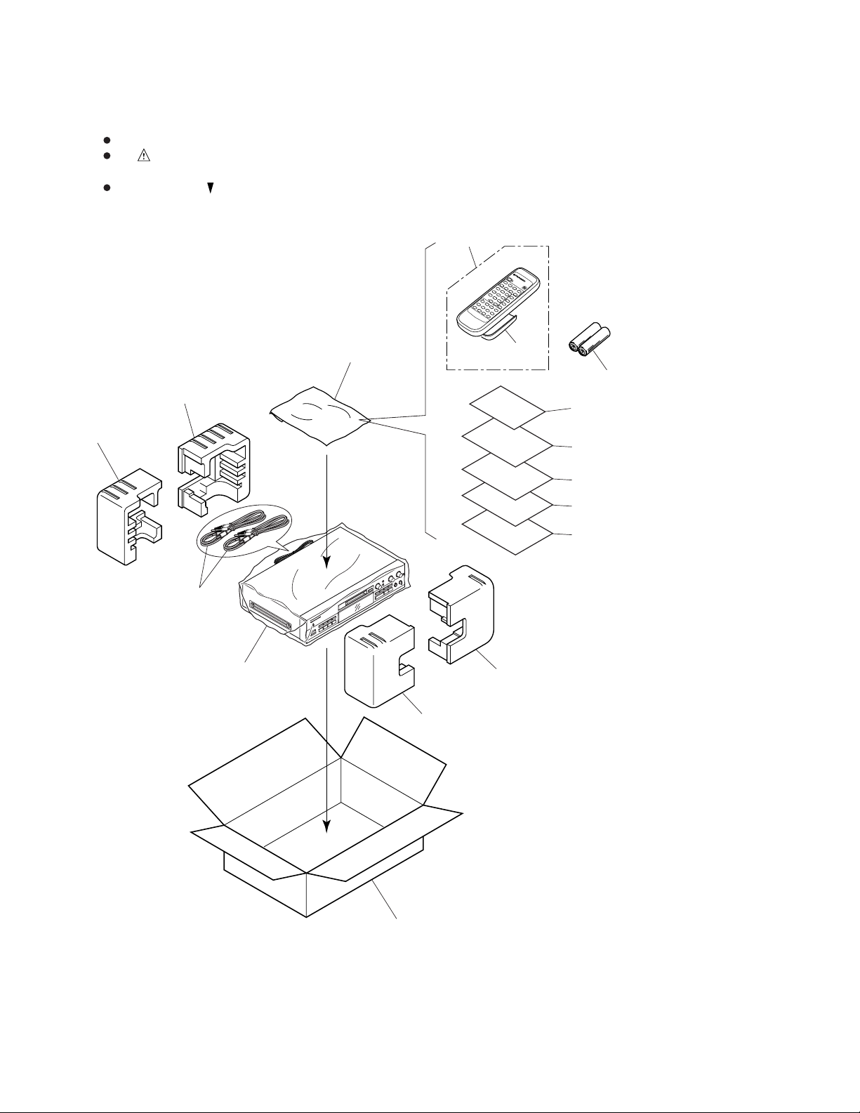
2.1 PACKING
MJ-D707, MJ-17D
5
3 Packing Case RHG1876 RHG1874 RHG1874 RHG1877
NSP 10 Warranty Card ARY1044 ARY7008 ARY7008 ARY1026
11 Operating Instructions (English/Spanish) RRE1162 RRE1162 Not used Not used
12 Operating Instructions (French/German) Not used RRD1198 RRD1198 Not used
13 Operating Instructions Not used RRD1199 Not used Not used
(Portuguese/Italian/Dutch/Swedish)
14 Operating Instructions (English) Not used Not used Not used RRB1185
Mark No. Description Part No.
(1) PACKING PARTS LIST
(2) CONTRAST TABLE
1 Protector (F) RHA1238
2 Protector (R) RHA1239
3 Packing Case
See Contrast table (2)
4 Sheet (750 × 600 × 0.5) Z23–007
5 Audio Cord (L= 1m) PDE1248
6 Remote Control Unit RPX1131
(CU-MJ011)
7 Battery Cover RZN1156
NSP 8 Batteries (AA/R6P) VEM–013
9 Polyethylene Bag Z21–038
(0.03 × 230 × 340)
NSP 10 Warranty Card
See Contrast table (2)
11 Operating Instructions
See Contrast table (2)
12 Operating Instructions
See Contrast table (2)
13 Operating Instructions
See Contrast table (2)
14 Operating Instructions
See Contrast table (2)
MJ-D707/KU, MY, MY/GR/FR and MJ-17D/KU are constructed the same except for the following:
KU MY MY/GR/FR KU
Part No.
Mark
Remarks
Symbol and Description
No.
MJ-D707 MJ-17D
MJ-D707, MJ-17D
6
A
B
D
B
C
A
D
C
21
27
21
22
36
32
21
26
19
21
18
18
13
8
7
21
2
21
6
21
3
4
21
21
24
25
28
25
24
29
21
17
11
15
37
12
33
33
1
5
21
10
9
14
21
31
30
21
9
10
21
16
21
23
MY and MY/GR/FR
types only
23
22
36
CN402
CN403
CN601
CN602
CN401
Refer to “2.3 FRONT PANEL SECTION”.
Refer to “2.4 MD
MECHANISM ASSY”.
34
35
20 (Except MJ-17D/KU)
MJ-17D/KU only
MJ-17D/KU only
20 (Except MJ-17D/KU)
2.2 EXTERIOR
MJ-D707, MJ-17D
7
1 MAIN UNIT ASSY RWZ4309 RWZ4293 RWZ4293 RWZ4288
2 TRANS UNIT ASSY RWZ4313 RWZ4297 RWZ4297 RWZ4292
3 Strain Relief CM–22C CM–22B CM–22B CM–22C
4 AC Power Cord PDG1015 PDG1003 PDG1003 PDG1015
6 Fuse (1A/125V) REK1075 Not used Not used REK1075
6 Fuse (500mAL250V) Not used REK1019 REK1019 Not used
11 Rear Panel RNA2204 RNA2204 RNA2204 RNA2205
20 Screw
FBT40P080FZK FBT40P080FZK FBT40P080FZK
Not used
24 Screw Not used Not used Not used PBA1103
25 Wood Collar Not used Not used Not used PNW1238
26 Gold Mole (L) Not used Not used Not used RAH2865
27 Gold Mole (R) Not used Not used Not used RAH2866
28 Side Wood (L) Not used Not used Not used RMS1019
29 Side Wood (R) Not used Not used Not used RMS1020
30 Caution Label Not used RRW1233 RRW1233 Not used
31 Caution Label Not used VRW1094 VRW1094 Not used
34 Fuse Label RRW1294 Not used Not used RRW1294
37 Fuse Caution Label RRW–111 Not used Not used RRW–111
Mark No. Description Part No.
(1) EXTERIOR PARTS LIST
(2) CONTRAST TABLE
1 MAIN UNIT ASSY
See Contrast table (2)
2 TRANS UNIT ASSY
See Contrast table (2)
3 Strain Relief
See Contrast table (2)
4 AC Power Cord
See Contrast table (2)
5 Lead Card 30P RDD1402
6 Fuse
See Contrast table (2)
7 Power Transformer RTT1316
NSP 8 PCB Holder PNW2100
9 Float Screw RBA1133
10 Float Rubber REB1328
11 Rear Panel
See Contrast table (2)
12 Mecha Angle RNB1133
13 Under Base RNB1134
14 Shield Case RNB1139
NSP 15 PC Support VEC1549
NSP 16 MD Mechanism Assy RXA1773
17 Bonnet PYY1147
18 Insulator PNW2766
19 POWER Button B RAC2207
20 Screw
See Contrast table (2)
MJ-D707/KU, MY, MY/GR/FR and MJ-17D/KU are constructed the same except for the following:
KU MY MY/GR/FR KU
Part No.
Mark
Remarks
Symbol and Description
No.
MJ-D707 MJ-17D
21 Screw IBZ30P060FCC
22 Screw IBZ30P080FCC
23 Binder ZCA–SKB90BK
24 Screw
See Contrast table (2)
25 Wood Collar
See Contrast table (2)
26 Gold Mole (L)
See Contrast table (2)
27 Gold Mole (R)
See Contrast table (2)
28 Side Wood (L)
See Contrast table (2)
29 Side Wood (R)
See Contrast table (2)
30 Caution Label
See Contrast table (2)
31 Caution Label
See Contrast table (2)
32 Screw BBT30P080FCC
33 Screw RBA1132
34 Fuse Label
See Contrast table (2)
35 Case Spacer REB1330
36 Plate VNE1164
37 Fuse Caution Label
See Contrast table (2)
Mark No. Description Part No.
MJ-D707, MJ-17D
8
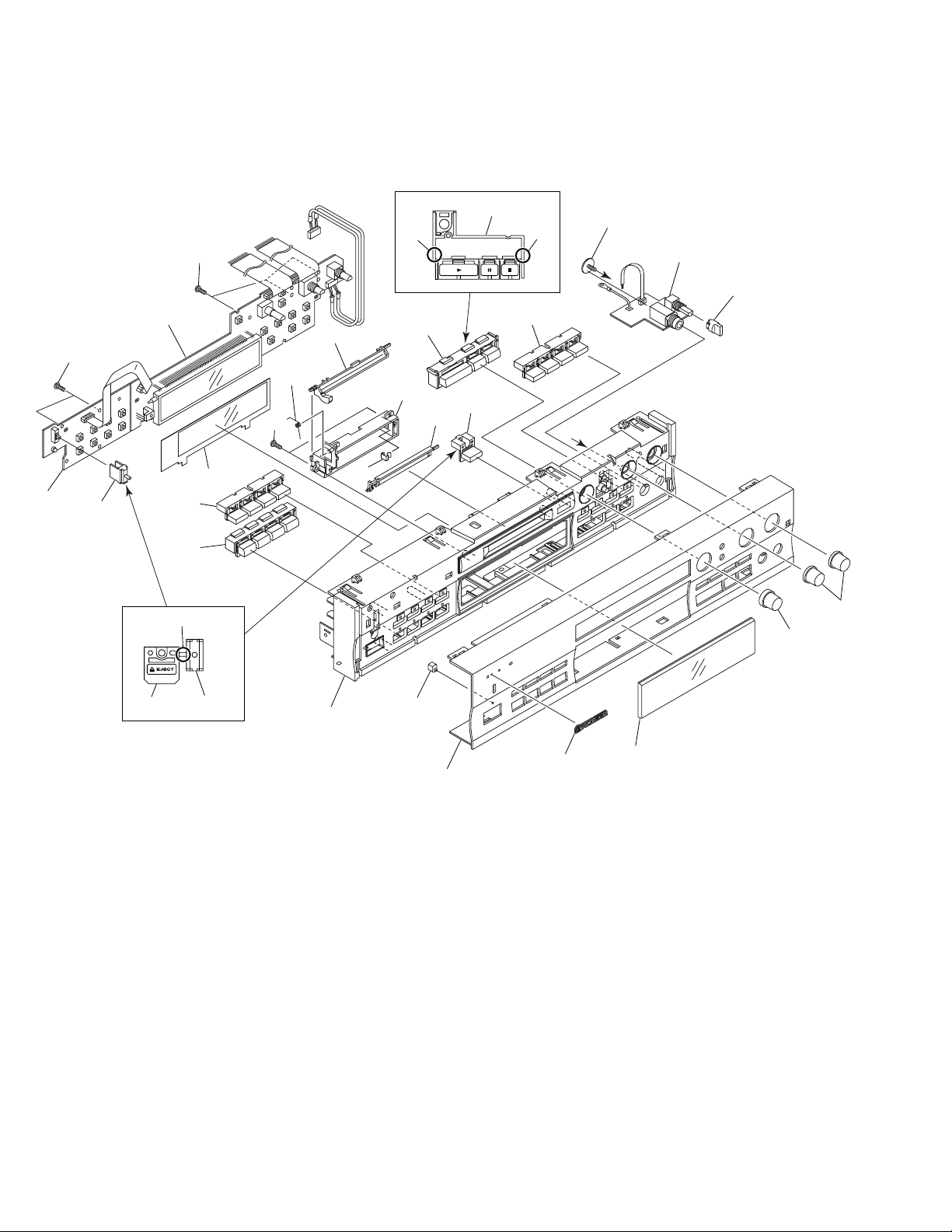
2.3 FRONT PANEL SECTION
A
A
1
2
14
15
21
9
17
7
19
13
10
20
18
23
23
12 (1/2)
12 (2/2)
11
16
22
3
8
12 (1/2)12 (2/2)
Cut
Cut
Cut
Not used
23
6
5
4
24

MJ-D707, MJ-17D
9
Mark No. Description Part No.
(1) FRONT PANEL SECTION PARTS LIST
1 DISPLAY UNIT ASSY
See Contrast table (2)
2 CONTROL UNIT ASSY
See Contrast table (2)
3 HEADPHONE UNIT ASSY
See Contrast table (2)
4 Door Holder RAH2852
5 Door Cam RAH2853
6 Door Spring RBH1459
7 Name Plate AAM7004
8 HEADPHONE Knob PAC1707
9 LED Lens PNW2019
10 VOL Knob RAC2197
11 PLAY Button B RAC2204
12 Slide Knob B RAC2208
13 JOG Knob B RAC2210
14 PLAY MODE Button B RAC2212
15 REC MODE Button B RAC2214
16 SEARCH Button B RAC2216
17 Front Panel
See Contrast table (2)
18 Door
See Contrast table (2)
19 Display Window RAH2862
20 FL Sheet
See Contrast table (2)
21 Panel Stay B RNT1250
22 Screw ABA7009
23 Screw PPZ30P100FMC
24 Edge Guard RBK1078
1 DISPLAY UNIT ASSY RWZ4310 RWZ4294 RWZ4294 RWZ4289
2 CONTROL UNIT ASSY RWZ4311 RWZ4295 RWZ4295 RWZ4290
3 HEADPHONE UNIT ASSY RWZ4312 RWZ4296 RWZ4296 RWZ4291
17 Front Panel RAH2870 RAH2859 RAH2859 RAH2860
18 Door RAH2861 RAH2861 RAH2861 RAH2851
20 FL Sheet RAH2863 RAH2855 RAH2855 RAH2863
(2) CONTRAST TABLE
MJ-D707/KU, MY, MY/GR/FR and MJ-17D/KU are constructed the same except for the following:
KU MY MY/GR/FR KU
Part No.
Mark
Remarks
Symbol and Description
No.
MJ-D707 MJ-17D
MJ-D707, MJ-17D
10
49
48
40
22
42
38
43
40
33
44
31
28
32
34
40
11
5
10
17
7
6
4
9
37
19
21
20
18
37
16
26
15
13
14
37
12
53
52
51
A
E
E
F
F
G
G
H
A
B
B
C
C
D
D
37
8
40
24
25
39
27
41
35
36
29
3946
23
30
45
2
3
50 47
37
CN103
CN101
CN102
CN105
1
H
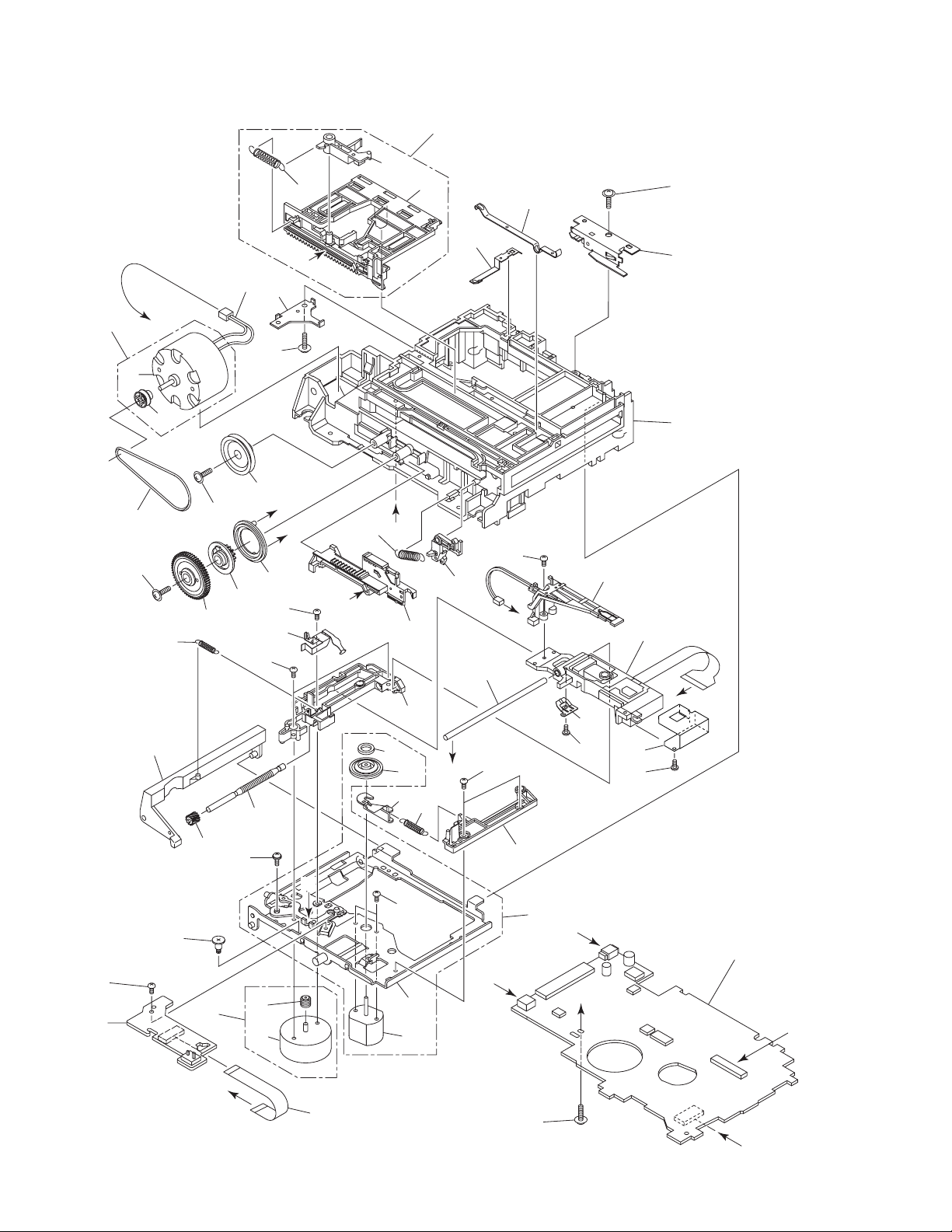
2.4 MD MECHANISM ASSY

MJ-D707, MJ-17D
11
Mark No. Description Part No.
MD MECHANISM ASSY PARTS LIST
1 CORE MAIN UNIT ASSY RWZ4271
2 CORE SW UNIT ASSY RWZ4272
3 Lead Card 7P RDD1399
4 Lead Wire RKP1814
5 Lever Spring RBH1463
6 Clamp Spring 1 RBK1074
7 Clamp Spring 2 RBK1075
8 Loading Belt REB1329
9 Lock Plate RNE1949
10 Loading Base RNK2312
11 Under Slider RNK2314
12 Gear Pulley RNK2316
13 Drive Gear RNK2317
14 Clutch Gear RNK2318
15 Flip Disk RNK2319
16 SW Lever RNK2320
17 Shutter Assy RXA1774
NSP 18 Upper Slider Assy RXA1775
19 Eject Spring RBH1461
20 Upper Slider RNK2313
21 Carrier RNK2315
22 Screw RBA1129
23 Spindle Spring RBH1460
24 Lifter SP RBH1462
25 Screw Guide RBK1072
26 S. H. Spring RBK1073
27 Guide Shaft RLA1310
28 Lead Screw RLA1311
29 Shield Case RNE1950
30 Reference Plate RNK2306
31 S. Holder RNK2307
32 Worm Wheel RNK2309
33 Hook RNK2310
34 Head Lifter RNK2311
35 MD Head RPB1062
36 MD Pick-up RWY1018
37 Screw IPZ20P080FMC
38 Screw JFZ17P020FZK
39 Screw JGZ14P020FMC
40 Screw JGZ17P030FMC
Mark No. Description Part No.
41 Screw JGZ17P040FZK
42 Screw PMB20P040FMC
43 Servo Base Assy REA1283
NSP 44 Clamp Magnet RMF1002
NSP 45 Servo Base RNE1946
NSP 46 Disc Table RNK2305
NSP 47 Spindle Motor RXM1091
48 Carriage Motor Assy REA1284
49 Worm RNK2308
NSP 50 Carriage Motor RXM1090
51 Loading Motor Assy REA1285
52 DC Motor /0.75W PXM1010
53 CA Pulley (1) VNL1197
MJ-D707, MJ-17D
12
A
B
C
D
1
23
4
1234
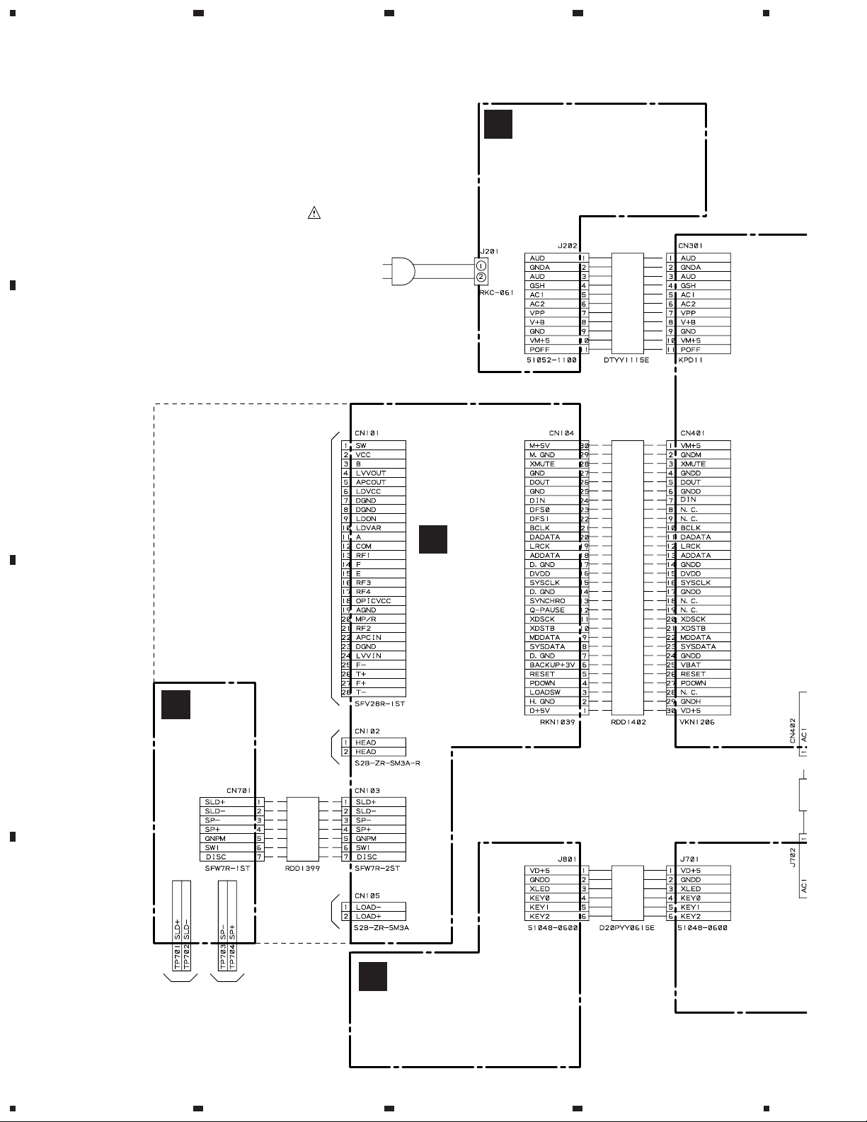
3. SCHEMATIC DIAGRAM
3.1 OVERALL CONNECTIONS
(MJ-D707/KU : RWZ4313)
(MJ-D707/MY : RWZ4297)
(MJ-D707/MY/GR/FR : RWZ4297)
(MJ-17D/KU : RWZ4292)
TRANS UNIT ASSY
D
(MJ-D707/KU : RWZ4311)
(MJ-D707/MY : RWZ4295)
(MJ-D707/MY/GR/FR : RWZ4295)
(MJ-17D/KU : RWZ4290)
CONTROL UNIT ASSY
F
CORE MAIN
UNIT ASSY
(RWZ4271)
MD MECHANISM
ASSY
(RXA1773)
A
CORE SW
UNIT ASSY
(RWZ4272)
B
PARALLEL JUMPER
PARALLEL
JUMPER
LEAD CARD
LEAD CARD
To
LOADING
MOTOR
To
SPINDLE
MOTOR
To
SLED
MOTOR
To
REC HEAD
To
PICKUP
(ORANGE)
(BLUE)
(BLACK)
(RED)
AC POWER CORD
KU type : PDG1015
(AC120V/60Hz)
MY, MY/GR/FR type : PDG1003
(AC220–230V, 50/60Hz)
MJ-D707, MJ-17D
13
A
B
C
D
5
678
5
6
7
8
Note : When ordering service parts, be sure to refer to "EXPLODED VIEWS and P AR TS LIST" or "PCB PAR TS LIST".
(MJ-D707/KU : RWZ4309)
(MJ-D707/MY : RWZ4293)
(MJ-D707/MY/GR/FR : RWZ4293)
(MJ-17D/KU : RWZ4288)
MAIN UNIT ASSY
C
(MJ-D707/KU : RWZ4312)
(MJ-D707/MY : RWZ4296)
(MJ-D707/MY/GR/FR : RWZ4296)
(MJ-17D/KU : RWZ4291)
HEADPHONE UNIT ASSY
G
(MJ-D707/KU : RWZ4310)
(MJ-D707/MY : RWZ4294)
(MJ-D707/MY/GR/FR : RWZ4294)
(MJ-17D/KU : RWZ4289)
DISPLAY UNIT ASSY
E
PARALLEL JUMPER PARALLEL JUMPER
PARALLEL
JUMPER
C
1/2,
C
2/2
( )
MJ-D707, MJ-17D
14
A
B
C
D
1
23
4
1234
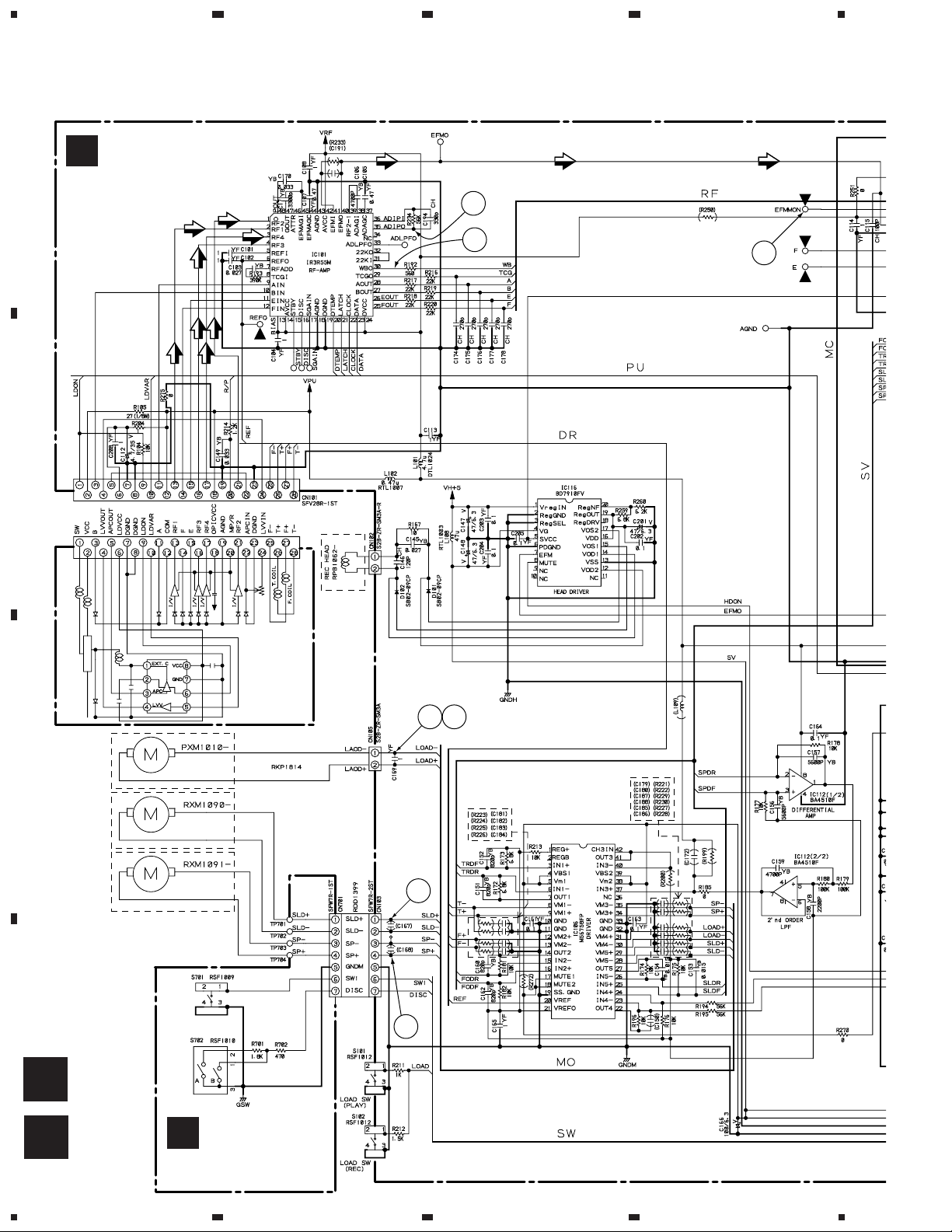
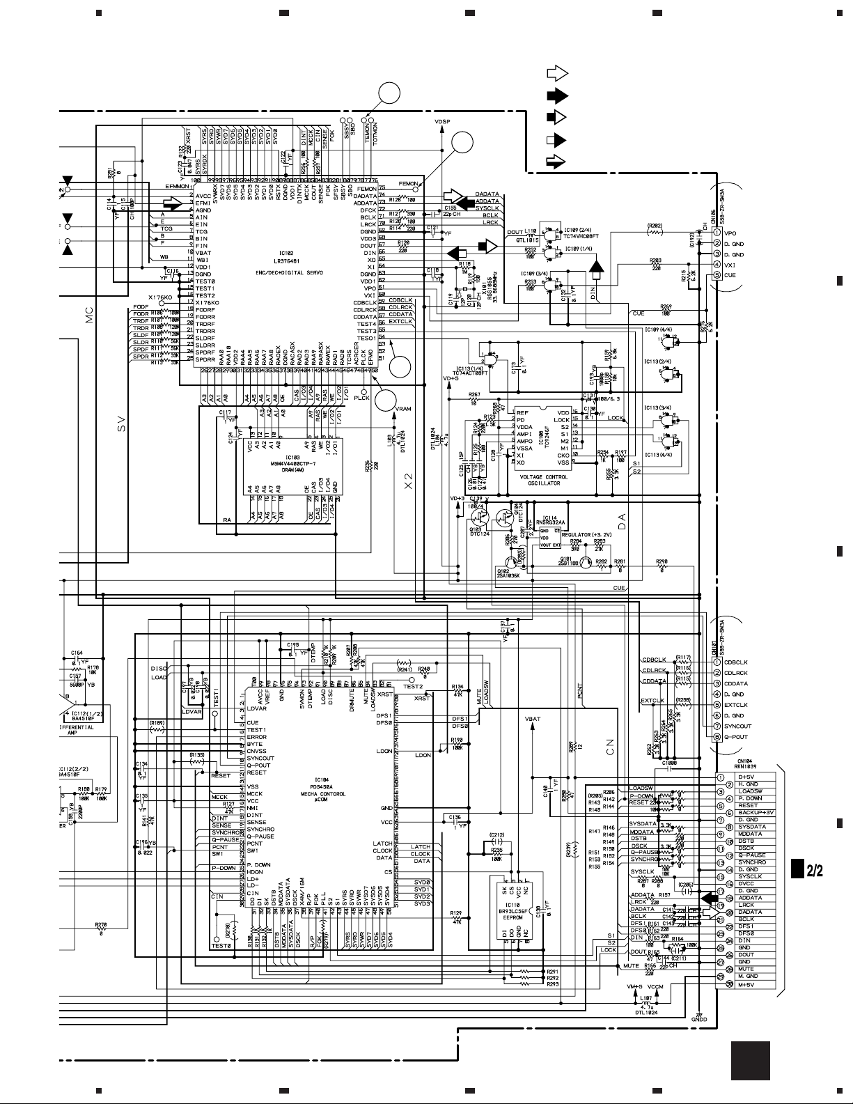
3.2 CORE MAIN UNIT and CORE SW UNIT ASSEMBLIES
B
A
CORE MAIN
UNIT ASSY
(RWZ4271)
A
CORE SW
UNIT ASSY
(RWZ4272)
B
LOADING MOTOR
SLED MOTOR
SPINDLE MOTOR
YELLOW
BLACK
ORANGE
BLUE
BLACK
RED
INSIDE SW
A : DISC PROTECT
B : DISC MEDIA DETECT
PICKUP
1
2
3
1011
8
9
MJ-D707, MJ-17D
15
A
B
C
D
5
678
5
6
7
8
A
(INSIDE)
C
CN401
YB
0.01
R291–R293 : 47k
: PLAYBACK SIGNAL
: REC SIGNAL
: OUTPUT DIGITAL AUDIO SIGNAL
: INPUT DIGITAL AUDIO SIGNAL
: RF SIGNAL
SIGNAL ROUTE
6
5
7
4
¶ 1 – - are waveform Nos. on pages 26 and 27.
MJ-D707, MJ-17D
16
1.53V
3.18V
1.65V
0V
1.42V
0V
1.59V
1.41V
1.97V
1.39V
1.64V
3.18V
0V
0V
0V
0V
1.69V
1.52V
1.70V
1.47V
1.47V
1.65V
1.54V
1.69V
1.51V
0.82V
2.0V
2.0V
1.81V
1.4V
0.82V
1.67V
1.67V
1.67V
2.86V
1.32V
2.23V
0V
2.4V
1.2V
1.5V
0V
2.0V
3.0V
1.2V
1.2V
0.02V
3.04V
1.57V
0.05V
9
8
7
6
5
4
3
2
1
30
29
28
27
26
25
24
23
22
21
20
19
18
17
16
15
14
13
12
11
10
49
48
47
46
45
44
43
42
41
40
39
38
37
36
35
34
33
32
31
PIN
NO.
VOLTAGE
50
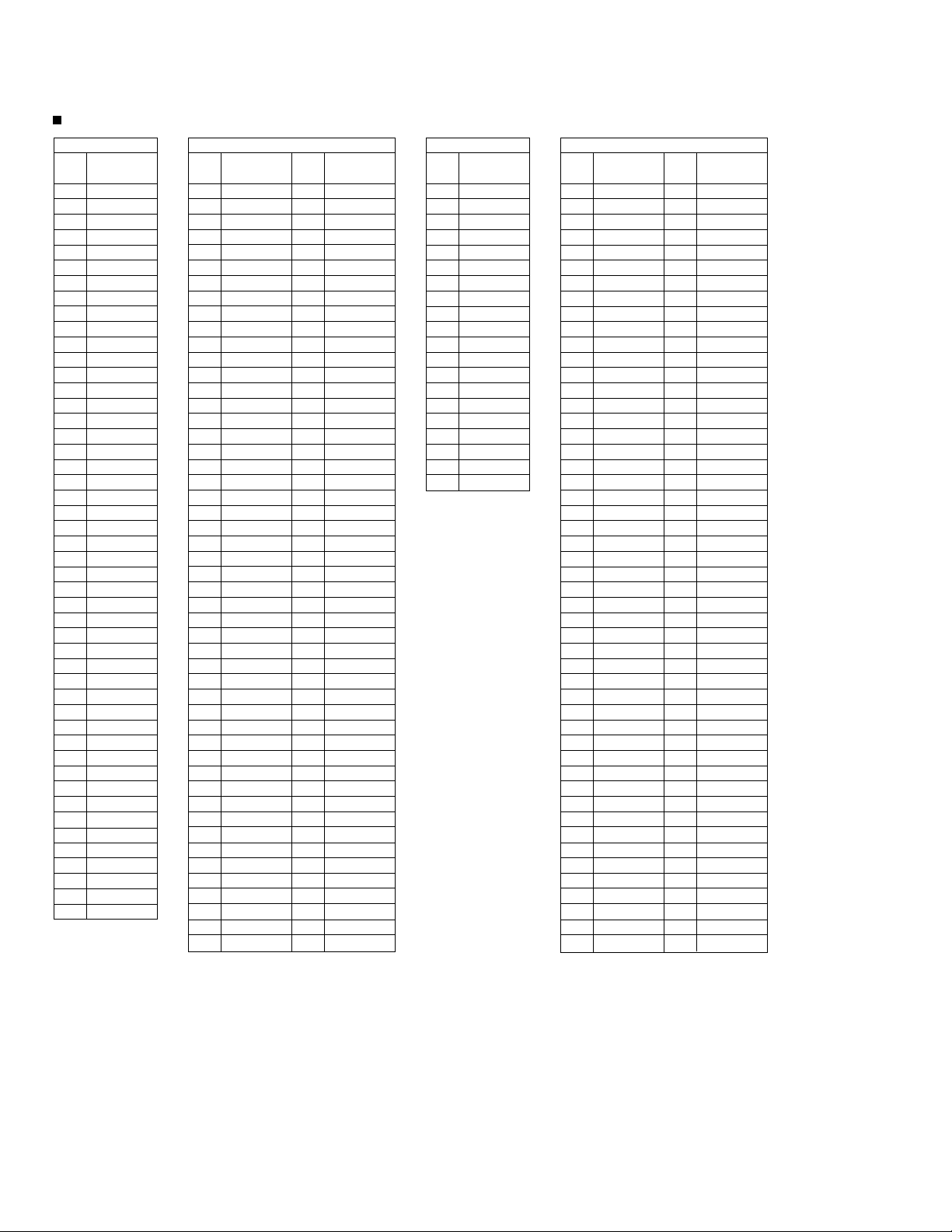
IC102
1.59V
0V
0V
1.59V
1.8V
0V
0V
0V
0V
0V
0.56V
3.18V
0V
1.5V
1.5V
3.2V
1.6V
3.2V
0V
1.6V
1.6V
1.48V
0V
0V
1.68V
1.82V
1.59V
0.35V
0.02V
3.2V
3.2V
0.02V
0.03V
1.9V
1.56V
3.1V
3.2V
0V
3.19V
0.5V
0.5V
0.5V
0.5V
0.9V
0.5V
0.5V
0.5V
0.8V
3.18V
0.06V
59
58
57
56
55
54
53
52
51
79
78
77
76
75
74
73
72
71
70
69
68
67
66
65
64
63
62
61
60
98
97
96
95
94
93
92
91
90
89
88
87
86
85
84
83
82
81
80
PIN
NO.
VOLTAGE
99
100
0V
0V
0.22V
0.03V
1.29V
2.21V
3.13V
0V
0V
0V
0V
3.03V
1.43V
0V
1.57V
3.2V
3.19V
3.1V
0.03V
0V
0V
3.18V
3.2V
0V
2.67V
3.19V
0V
0V
2.4V
0.24V
0V
0.3V
3.2V
1.56V
1.0V
0V
2.77V
0V
3.18V
0.02V
3.19V
3.2V
0V
0.05V
3.18V
3.19V
0.51V
0.4V
0.3V
0.55V
9
8
7
6
5
4
3
2
1
30
29
28
27
26
25
24
23
22
21
20
19
18
17
16
15
14
13
12
11
10
49
48
47
46
45
44
43
42
41
40
39
38
37
36
35
34
33
32
31
PIN
NO.
VOLTAGE
50
IC104
0.54V
0.6V
0.6V
0.6V
0V
0V
0V
0V
3.2V
0V
0V
3.2V
0V
0V
3.2V
0V
0V
0V
0V
0V
0V
3.1V
3.2V
0V
0V
3.2V
0V
0V
0V
3.2V
0V
3.19V
0V
3.19V
0V
3.18V
3.2V
0V
1.03V
1.6V
0.56V
1.49V
1.49V
0.68V
0.61V
0V
0.53V
3.2V
3.2V
0V
59
58
57
56
55
54
53
52
51
79
78
77
76
75
74
73
72
71
70
69
68
67
66
65
64
63
62
61
60
98
97
96
95
94
93
92
91
90
89
88
87
86
85
84
83
82
81
80
PIN
NO.
VOLTAGE
99
100
0.78V
0.73V
0.77V
0.75V
1.61V
1.61V
0.75V
1.61V
1.61V
1.61V
1.61V
1.61V
3.19V
3.19V
0V
0V
3.19V
0V
0V
1.5V
3.2V
0V
0V
3.19V
2.0V
0V
1.40V
1.42V
1.40V
1.63V
1.61V
1.61V
0V
0V
0V
1.62V
0.59V
1.61V
1.61V
1.61V
1.61V
3.19V
0V
1.08V
1.61V
1.61V
0V
0.74V
9
8
7
6
5
4
3
2
1
30
29
28
27
26
25
24
23
22
21
20
19
18
17
16
15
14
13
12
11
10
42
43
44
45
46
47
48
41
40
39
38
37
36
35
34
33
32
31
VOLTAGE
IC101
PIN
NO.
1.2V
1.2V
3.0V
2.0V
0V
2.23V
1.32V
2.86V
1.67V
3.18V
1.67V
1.67V
1.67V
2.86V
1.32V
2.23V
2.4V
1.2V
1.5V
0V
9
5
4
3
2
1
26
25
24
23
22
18
17
16
15
14
13
12
11
10
PIN
NO.
VOLTAGE
IC103
Voltages of CORE MAIN UNIT ASSY
MJ-D707, MJ-17D
17
9
8
7
6
5
4
3
2
1
16
15
14
13
12
11
10
PIN
NO.
VOLTAGE
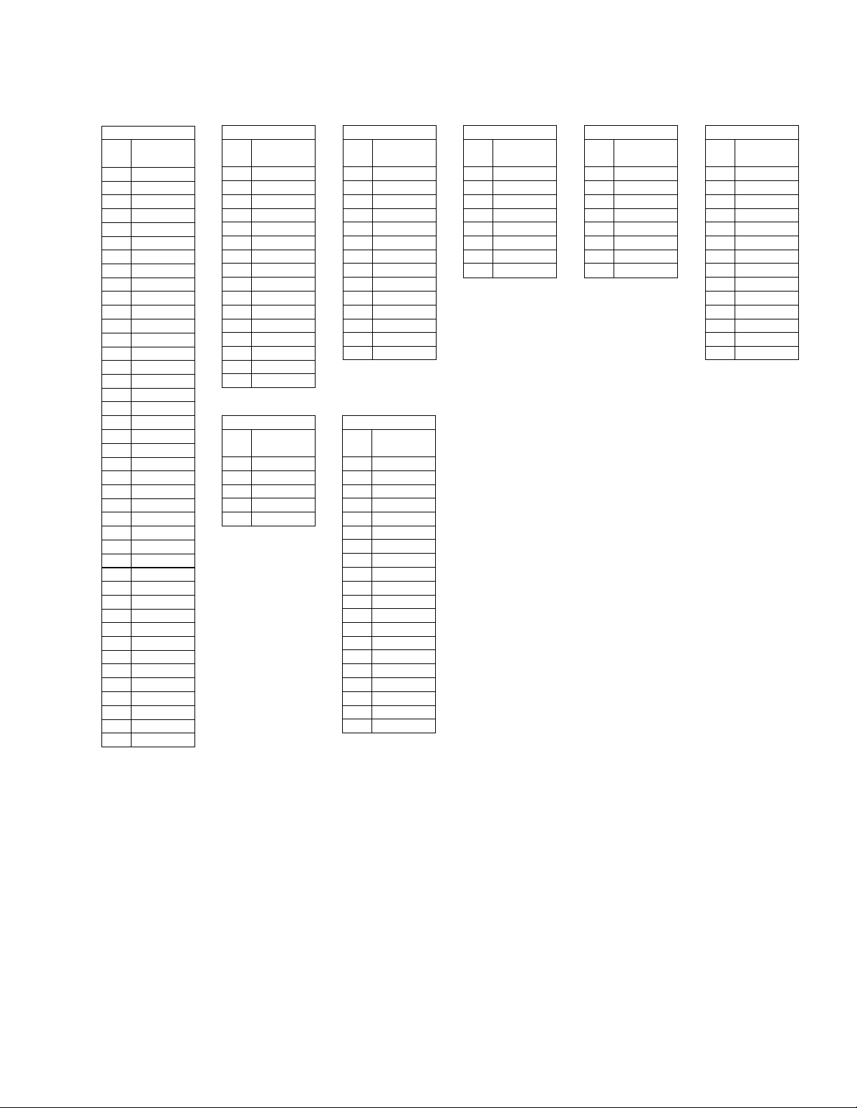
IC108
2.47V
2.63V
4.87V
2.63V
1.59V
0V
0V
4.87V
0V
2.25V
4.94V
4.94V
4.94V
4.94V
3.12V
4.94V
9
8
7
6
5
4
3
2
1
14
13
12
11
10
PIN
NO.
VOLTAGE
IC109
2.77V
2.77V
3.2V
1.58V
1.58V
1.56V
0V
0V
0V
0V
0V
0V
0V
3.2V
9
8
7
6
5
4
3
2
1
20
19
18
17
16
15
14
13
12
11
10
PIN
NO.
VOLTAGE
IC116
4.98V
0V
0V
4.99V
3.2V
0V
0.03V
3.18V
0V
0V
0V
0.22V
0V
0.25V
0.25V
2.82V
0.16V
4.94V
2.82V
1.33V
1.6V
0.49V
1.61V
4.99V
4.99V
1.61V
1.62V
2.46V
2.51V
0V
0V
2.54V
2.45V
1.62V
1.62V
1.61V
3.17V
0V
1.61V
1.61V
1.61V
1.61V
1.36V
1.36V
1.61V
1.61V
1.63V
2.41V
2.55V
2.47V
2.48V
0V
0V
2.79V
2.18V
0V
1.69V
5.0V
4.99V
1.67V
1.69V
1.69V
9
8
7
6
5
4
3
2
1
30
29
28
27
26
25
24
23
22
21
20
19
18
17
16
15
14
13
12
11
10
42
41
40
39
38
37
36
35
34
33
32
31
VOLTAGE
IC106
PIN
NO.
1.66V
1.62V
1.62V
0V
1.67V
1.67V
1.67V
3.19V
8
7
6
5
4
3
2
1
PIN
NO.
VOLTAGE
IC112
0V
3.2V
0V
3.2V
0V
0.11V
0V
0V
8
7
6
5
4
3
2
1
PIN
NO.
VOLTAGE
IC110
9
8
7
6
5
4
3
2
1
14
13
12
11
10
PIN
NO.
VOLTAGE
IC113
4.95V
3.96V
0V
0V
0V
0V
0V
0V
4.94V
4.12V
3.19V
0V
0V
4.94V
0V
4.19V
3.21V
2.81V
0V
5
4
3
2
1
PIN
NO.
VOLTAGE
IC114
MJ-D707, MJ-17D
18
A
B
C
D
1
23
4
1234
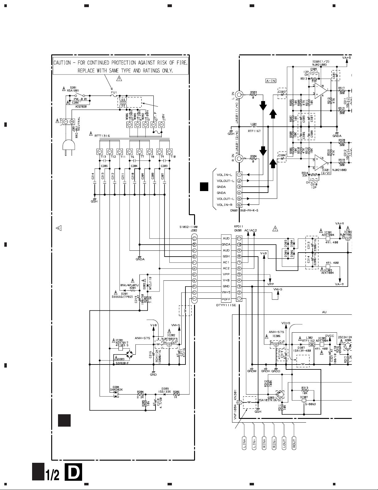
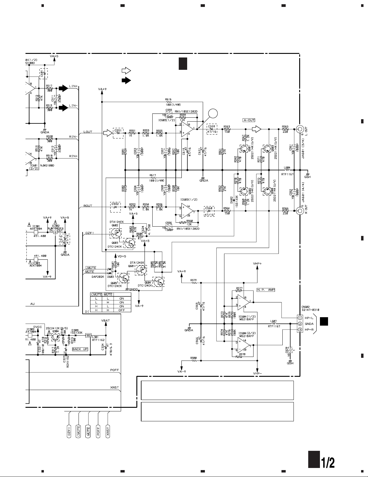
3.3 MAIN UNIT ASSY (1/2) and TRANS UNIT ASSY
E
J704
POWER TRANSFORMER
HEAT SINK
L203 : RTF1167
MY and MY/GR/FR
types only
L202 : RTF1167
MY and MY/GR/FR
types only
HEAT SINK
BA05T
(MJ-D707/KU : RWZ4313)
(MJ-D707/MY : RWZ4297)
(MJ-D707/MY/GR/FR : RWZ4297)
(MJ-17D/KU : RWZ4292)
TRANS UNIT ASSY
D
AC POWER CORD
KU type : PDG1015
(AC120V/60Hz)
MY, MY/GR/FR type : PDG1003
(AC220–230V, 50/60Hz)
FU1 FUSE
KU type : REK1075 (1A/125V)
MY, MY/GR/FR type : REK1019 (500mA/250V)
JUMPER
KU type : W305
MY, MY/GR/FR type : W306
C203–C205, C207–C214 : CFTLA, 0.1
JA601 : RKB1032
D303–D306 : S5566G(TPB2)
C315, C319
MJ-D707/KU : CEAT470M16
other models : PCH1123
C503, C504
MJ-D707/KU : CEAT470M16
other models : CEBA220M25
C50
MJ-
D
oth
e
C313, C314
MJ-D707/KU : CEAT
other models : PCH1120 (C313)
: PCH1121 (C314)
S201 : POWER
H201, H202
: AKR1004
L201
VTL-262
MY and MY/GR/FR
types only
MY and MY/GR/FR
types only
L305
RTF1167
L304
RTF1167
MY and MY/GR/FR
types only
C
MJ-D707, MJ-17D
19
A
B
C
D
5
678
5
6
7
8
G
J901
C
1/2
LINE MUTE
(MJ-D707/KU : RWZ4309)
(MJ-D707/MY : RWZ4293)
(MJ-D707/MY/GR/FR : RWZ4293)
(MJ-17D/KU : RWZ4288)
MAIN UNIT ASSY (1/2)
T470M16
1123
C551, C552, C559, C560
MJ-D707/KU : CEAT
other models : CEBA
C505 – C508, C601
MJ-D707/KU : CEAT470M16
other models : RCH1133
120 (C313)
121 (C314)
IC603 : NJM4580D
CAUTION : FOR CONTINUED PROTECTION AGAINST RISK OF FIRE.
REPLACE ONLY WITH SAME TYPE NO. 491.400 MFD, BY
LITTELFUSE INK. FOR IC301, IC303, IC305(AEK7004).
CAUTION : FOR CONTINUED PROTECTION AGAINST RISK OF FIRE.
REPLACE ONLY WITH SAME TYPE NO. 49103.5 MFD, BY
LITTELFUSE INK. FOR IC201(AEK7017).
Y/GR/FR
2.2/50
2.2/50
470k470k
100 (1/4W)
100 (1/4W)
68k
68k
18
: PLAYBACK SIGNAL
: REC SIGNAL
SIGNAL ROUTE
C
¶ % is waveform Nos. on page 27.
MJ-D707, MJ-17D
20
A
B
C
D
1
23
4
1234
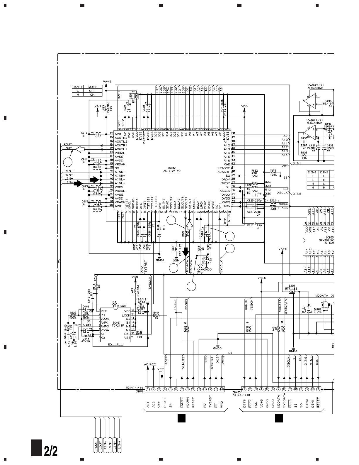
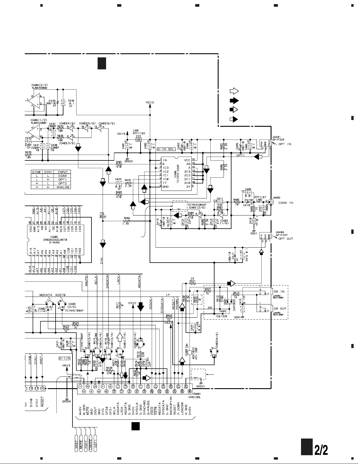
3.4 MAIN UNIT ASSY (2/2)
E
J702
E
J703
DSP (built-in 20 bit ADC/DAC)
C604, C612, C616
MJ-D707/KU : CEAT470M16
other models : VCH1081
C614
MJ-D707/KU : CEAT221M6R3
other models : VCH1081
L306 : RT
F
MY and M
types only
12
16
14
15
13
17
C
MJ-D707, MJ-17D
21
A
B
C
D
5
678
5
6
7
8
A
CN104
C
2/2
(MJ-D707/KU : RWZ4309)
(MJ-D707/MY : RWZ4293)
(MJ-D707/MY/GR/FR : RWZ4293)
(MJ-17D/KU : RWZ4288)
MAIN UNIT ASSY (2/2)
RKB1021
R455 : MY, MY/GR/FR types only
KU type only
L406
RTF1167
L307
RTF1167
MY and MY/GR/FR
types only
MY and MY/GR/FR
types only
L306 : RTF1167
MY and MY/GR/FR
types only
: PLAYBACK SIGNAL
: REC SIGNAL
: OUTPUT DIGITAL AUDIO SIGNAL
: INPUT DIGITAL AUDIO SIGNAL
SIGNAL ROUTE
C
¶ = – # are waveform Nos. on pages 26 and 27.
 Loading...