


MEV-51
STANDBY/ON
SURROUND
POWER AMPLIFIER EV51DVD
STANDBY
ADVANCED
SURROUND
PHONES
STEREO POWER AMPLIFIER
M-EV51
THIS MANUAL IS APPLICABLE TO THE FOLLOWING MODEL(S) AND TYPE(S).
Type
DLXJ/NC AC110-127V/220-230V/240V With the voltage selector
Model
M-EV51 the following method.
Power Requirement
¶ This product is a system(s) component.
This product does not function properly independently ; to avoid malfunctions, be
sure to connect it to the prescribed system component(s), otherwise damage may
result.
¶ Please connect it to the
Component Model Service manual Remarks
STEREO DVD TUNER DECK
XV-EV51 for operation inspection.
The voltage can be converted by
ORDER NO.
RRV2663
STEREO DVD TUNER DECK XV-EV51 RRV2636
STEREO POWER AMPLIFIER M-EV51 RRV2663 This manual
SPEAKER SYSTEM S-EV51 RRV2640
For details, refer to "Important symbols for good services" on the next page.
PIONEER CORPORATION 4-1, Meguro 1-chome, Meguro-ku, Tokyo 153-8654, Japan
PIONEER ELECTRONICS (USA) INC. P.O. Box 1760, Long Beach, CA 90801-1760, U.S.A.
PIONEER EUROPE NV Haven 1087, Keetberglaan 1, 9120 Melsele, Belgium
PIONEER ELECTRONICS ASIACENTRE PTE. LTD. 253 Alexandra Road, #04-01, Singapore 159936
PIONEER CORPORATION 2002
T – ZZV JULY 2002 Printed in Japan
1
23
4
SAFETY INFORMATION
A
This service manual is intended for qualified service technicians; it is not meant for the casual
do-it-yourselfer. Qualified technicians have the necessary test equipment and tools, and have been
trained to properly and safely repair complex products such as those covered by this manual.
Improperly performed repairs can adversely affect the safety and reliability of the product and may
void the warranty . If you are not qualified to perform the repair of this product properly and safely, you
should not risk trying to do so and refer the repair to a qualified service technician.
WARNING
This product contains lead in solder and certain electrical parts contain chemicals which are known to the state of California to
B
cause cancer, birth defects or other reproductive harm.
Health & Safety Code Section 25249.6 – Proposition 65
NOTICE
(FOR CANADIAN MODEL ONLY)
Fuse symbols (fast operating fuse) and/or (slow operating fuse) on PCB indicate that replacement
parts must be of identical designation.
REMARQUE
(POUR MODÈLE CANADIEN SEULEMENT)
Les symboles de fusible (fusible de type rapide) et/ou (fusible de type lent) sur CCI indiquent que
C
les pièces de remplacement doivent avoir la même désignation.
(FOR USA MODEL ONLY)
1. SAFETY PRECAUTIONS
The following check should be performed for the
continued protection of the customer and service
technician.
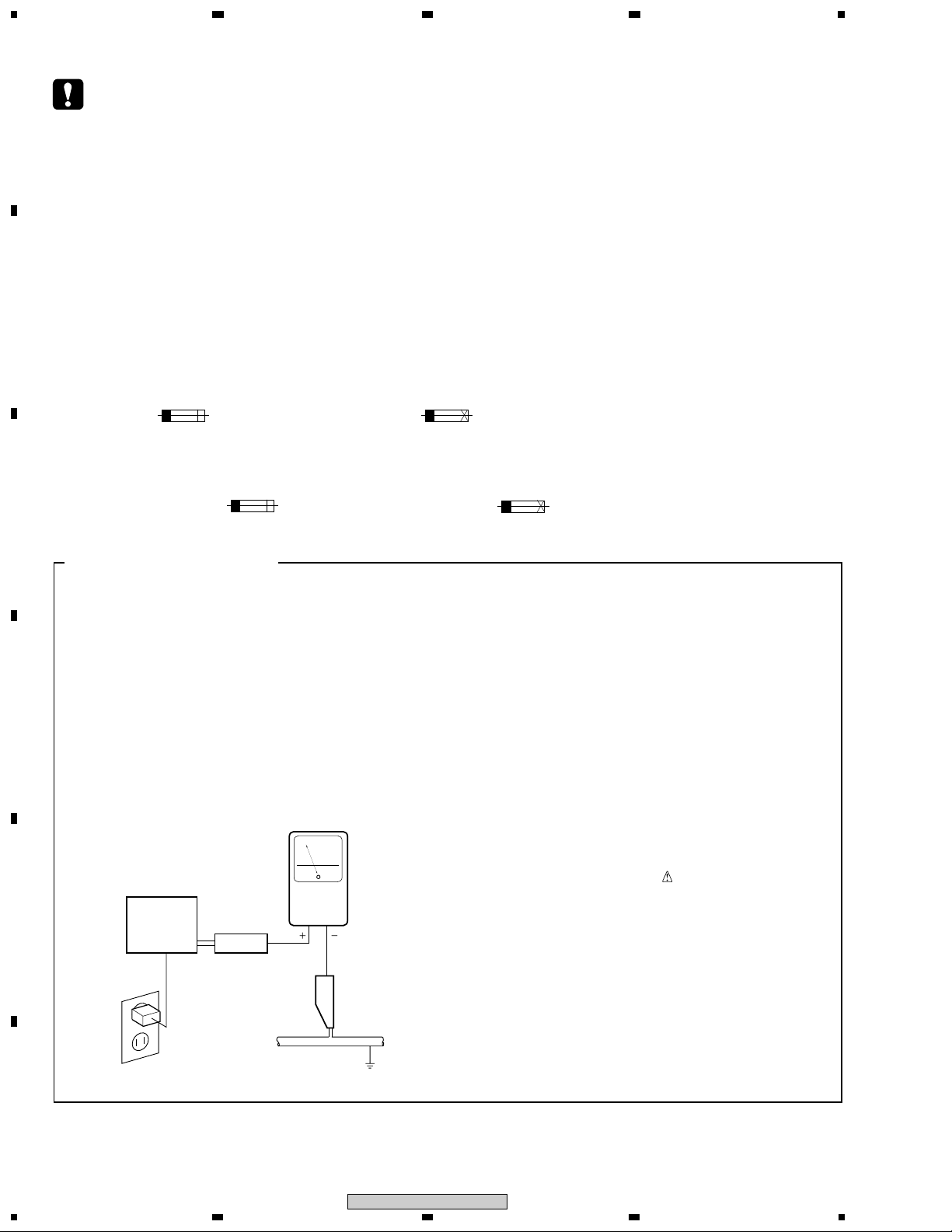
LEAKAGE CURRENT CHECK
Measure leakage current to a known earth ground
(water pipe, conduit, etc.) by connecting a leakage
D
E
current tester such as Simpson Model 229-2 or
equivalent between the earth ground and all exposed
metal parts of the appliance (input/output terminals,
screwheads, metal overlays, control shaft, etc.). Plug
the AC line cord of the appliance directly into a 120V
AC 60 Hz outlet and turn the AC power switch on. Any
current measured must not exceed 0.5 mA.
Reading should
not be above
0.5 mA
Earth
ground
Device
under
test
Also test with
plug reversed
(Using AC adapter
plug as required)
Test all
exposed metal
surfaces
Leakage
current
tester
AC Leakage Test
ANY MEASUREMENTS NOT WITHIN THE
LIMITS OUTLINED ABOVE ARE INDICATIVE
OF A POTENTIAL SHOCK HAZARD AND
MUST BE CORRECTED BEFORE RETURNING THE APPLIANCE TO THE CUSTOMER.
2. PRODUCT SAFETY NOTICE
Many electrical and mechanical parts in the appliance
have special safety related characteristics. These are
often not evident from visual inspection nor the
protection afforded by them necessarily can be obtained
by using replacement components rated for voltage,
wattage, etc. Replacement parts which have these
special safety characteristics are identified in this
Service Manual.
Electrical components having such features are
identified by marking with a
on the parts list in this Service Manual.
The use of a substitute replacement component which
does not have the same safety characteristics as the
PIONEER recommended replacement one, shown in the
parts list in this Service Manual, may create shock, fire,
or other hazards.
Product Safety is continuously under review and new
instructions are issued from time to time. For the latest
information, always consult the current PIONEER
Service Manual. A subscription to, or additional copies
of, PIONEER Service Manual may be obtained at a
nominal charge from PIONEER.
on the schematics and
F
2
1234
M-EV51
1
234
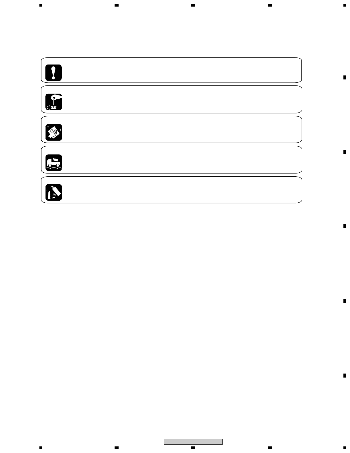
[ Important symbols for good services ]
In this manual, the symbols shown-below indicate that adjustments, settings or cleaning should be made securely.
When you find the procedures bearing any of the symbols, be sure to fulfill them:
1. Product safety
You should conform to the regulations governing the product (safety, radio and noise, and other regulations), and
should keep the safety during servicing by following the safety instructions described in this manual.
2. Adjustments
To keep the original performances of the product, optimum adjustments or specification confirmation is indispensable.
In accordance with the procedures or instructions described in this manual, adjustments should be performed.
3. Cleaning
For optical pickups, tape-deck heads, lenses and mirrors used in projection monitors, and other parts requiring cleaning,
proper cleaning should be performed to restore their performances.
4. Shipping mode and shipping screws
To protect the product from damages or failures that may be caused during transit, the shipping mode should be set or
the shipping screws should be installed before shipping out in accordance with this manual, if necessary.
5. Lubricants, glues, and replacement parts
Appropriately applying grease or glue can maintain the product performances. But improper lubrication or applying
glue may lead to failures or troubles in the product. By following the instructions in this manual, be sure to apply the
prescribed grease or glue to proper portions by the appropriate amount.For replacement parts or tools, the prescribed
ones should be used.
A
B
C
D
E
F
M-EV51
1
2
3
4
3

CONTENTS
SAFETY INFORMATION ......................................................................................................................................2
A
B
C
D
1. SPECIFICATIONS ............................................................................................................................................5
2. EXPLODED VIEWS AND PARTS LIST .......................................................................................................... 6
2.1 PACKING....................................................................................................................................................6
2.2 EXTERIOR .................................................................................................................................................8
3. SCHEMATIC DIAGRAM ................................................................................................................................ 10
3.1 OVERALL WIRING DIAGRAM................................................................................................................ 10
3.2 E-VOL ASSY 1/2 ..................................................................................................................................... 12
3.3 E-VOL ASSY 2/2 ..................................................................................................................................... 14
3.4 VHVL AMP ASSY.................................................................................................................................... 16
3.5 AMP REG FAN ASSY ............................................................................................................................. 18
3.6 SP-TERMINAL, HP, and DISPLAY ASSYS............................................................................................ 20
3.7 PRIMARY ASSY...................................................................................................................................... 22
3.8 SECONDARY ASSY ............................................................................................................................... 24
4. PCB CONNECTION DIAGRAM..................................................................................................................... 26
4.1 VHVL AMP ASSY.................................................................................................................................... 27
4.2 E-VOL and AMP DISPLAY ASSYS ........................................................................................................ 28
4.3 SP-TERMINAL and HP ASSYS .............................................................................................................. 32
4.4 PRIMARY ASSY...................................................................................................................................... 34
4.5 SECONDARY ASSY ............................................................................................................................... 36
4.6 AMP REG FAN ASSY ............................................................................................................................. 38
5. PCB PARTS LIST .......................................................................................................................................... 39
6. ADJUSTMENT ............................................................................................................................................... 41
7. GENERAL INFORMATION............................................................................................................................ 42
7.1 DIAGNOSIS............................................................................................................................................. 42
7.1.1 PROTECTION CIRCUIT.................................................................................................................. 42
7.1.2 OPERATING CONDITION FOR FAN ............................................................................................. 44
7.1.3 SINGLE OPERATION METHOD..................................................................................................... 46
7.1.4 DISASSEMBLY................................................................................................................................ 48
8. PANEL FACILITIES ....................................................................................................................................... 49
1
23
4
E
F
4
1234
M-EV51

1
1. SPECIFICATIONS
234
Amplifier section
Continuous Power Output:
Front..........................................80 W per channel
(1 kHz, 10%, 8 Ω)
Center .............................33 W (1 kHz, 10%, 8 Ω)
Surround ...................................33 W per channel
(1 kHz, 10%, 8 Ω)
Miscellaneous
Power Requirements
.............................. AC 110-127V/220-230V/240V
(switchable), 50/60 Hz
Power Consumption
Singapore, Malaysia
Hong Kong models ................................ 175 W
All other models ..................................... 465 W
Power Consumption in standby mode ........... 1 W
Dimensions:
Power Amplifier ....
170 (W) x 190 (H) x 254 (D) mm
Weight:
Power Amplifier ........................................... 5.3 kg
Accessories
Power cord..........................................................1
Video cord...........................................................1
System cable ...................................................... 2
FM antenna.........................................................1
AM loop antenna.................................................1
Dry cell batteries (AA/R6) ...................................2
Remote Control...................................................1
A
B
C
Note
Specifications and design subject to possible
modification without notice, due to improvements.
ACCESSORIES
System cable(8P)
(XDE3054)
Remote Control
(XXD3049)
STANDBY/ON
DVD/CD TAPE FM/AM LINE
AUDIO
SUBTITLE
DSP
ADVANCED
SURROUND
KEYCON
—
—
I
KARAOKE
ECHO
VOLUME
SYSTEM SETUP
TUNE +
DVD SETUP
ENTER
SOUND
MODE
TUNE –
/e
1
4
8
PROGRAM
REPEAT
123
TEST TONE
CH LEVEL
456
7890
TV CONTROL
INPUT
SHIFT
SELECT
ANGLE ZOOM
MONO
i
TIMER
CLOCK ADJ.
3
3
3
RANDOM
SLEEP
CHANNELVOLUME
DVD DISP
SYSTEM DISP
MUTE
TOP MENU
DVD MENU
RETURN
E/
¡
FOLDER +FOLDER –
¢
7
CLEAR
ENTER
System cable(20P)
(XDE3053)
Dry cell Batteries
(R6P,AA)
FM antenna
(ADH7004)
Video cable(L=1.5m)
(VDE1034)
yellow
Power cord
(XDG3001)
D
AM Loop antenna
(ATB7009)
E
F
M-EV51
1
2
3
4
5
1
23
2. EXPLODED VIEWS AND PARTS LIST
4
NOTES:
A
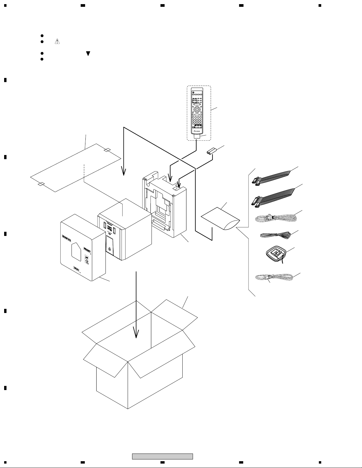
2.1 PACKING
B
C
Parts marked by "NSP" are generally unavailable because they are not in our Master Spare Parts List.
The mark found on some component parts indicates the importance of the safety factor of the part.
Therefore, when replacing, be sure to use parts of identical designation.
Screws adjacent to mark on product are used for disassembly.
For the applying amount of lubricants or glue, follow the instructions in this manual.
(In the case of no amount instructions, apply as you think it appropriate.)
STANDBY/ON
DVD/CD TAPE FM/AM LINE
SUBTITLE
ANGLE ZOOM
AUDIO
DVD DISP
DSP
ADVANCED
MONO
SYSTEM DISP
SURROUND
—
KEYCON —
I
i
KARAOKE
ECHO
TIMER
MUTE
CLOCK ADJ.
VOLUME
SYSTEM SETUP
TOP MENU
TUNE +
DVD MENU
10
DVD SETUP
SOUND
MODE
/e
1
4
PROGRAM
123
TEST TONE
456
7890
SHIFT
ENTER
RETURN
TUNE –
3
3
3
FOLDER +FOLDER –
7
8
REPEAT
RANDOM
CLEAR
CH LEVEL
SLEEP
ENTER
TV CONTROL
INPUT
CHANNELVOLUME
SELECT
2
E/
¡
¢
3
4
14
9
8
1
5
12
D
11
Yellow
6
7
13
E
F
6
M-EV51
1234

1
PACKING PARTS LIST
•
Mark No. Description Part No.
> 1 Power Cord XDG3001
2 Remote Control XXD3049
3 Battery Cover AZA7424
NSP 4 Battery (R6P,AA) VEM1031
5 FM Antenna ADH7004
6 AM Loop Antenna ATB7009
7 Video Cord (L=1.5m) VDE1034
8 System Cable 20P XDE3053
9 System Cable 8P XDE3054
10 Packing Sheet AHG7053
234
A
11 Front Pad A XHA3132
12 Rear Pad A XHA3133
13 Packing Case XHD3312
NSP 14 Literature Bag AHG1180
B
C
D
E
F
M-EV51
1
2
3
4
7
1
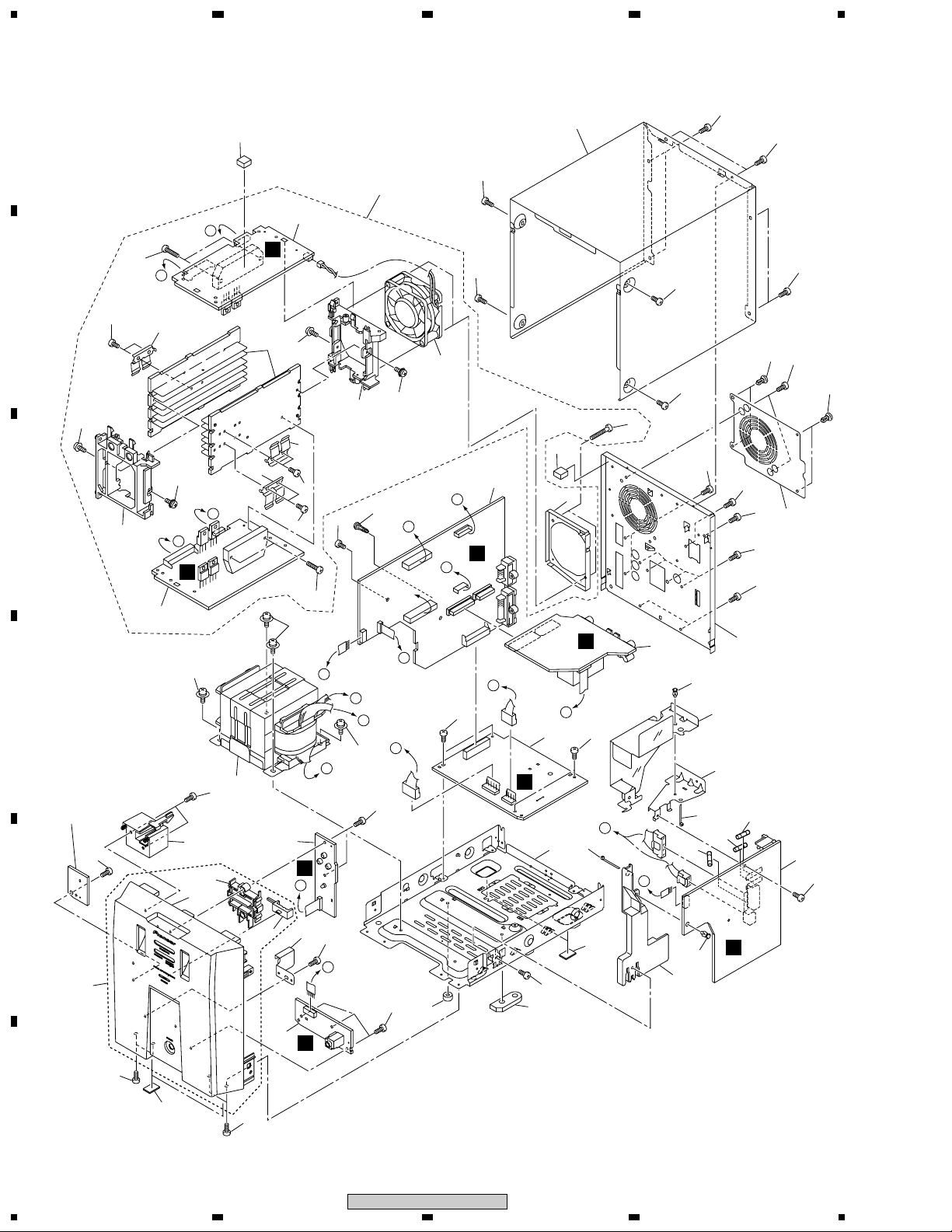
2.2 EXTERIOR
23
4
A
B
C
D
E
36
46
45
PCB abandoned
part (NSP)
38
27
47
42
2
50
31
37
49
3
I
36
36
C
36
23
36
23
36
21
38
36
9
7
34
40
35
50
1
I
A
G
41
D
E
34
A
34
8
48
37
35
38
38
4
14
23
22
15
H
25
10
18
26
10
G
20
36
13
D
26
J
19
H
43
46
46
44
42
46
F
42
36
G
36
38
51
H
B
47
33
33
24
30
28
38
11
29
B
E
33
C
6
F
B
16
38
A
5
E
J
D
C
38
38
17
36
19
F
8
1234
36
M-EV51

1
EXTERIOR PARTS LIST
•
Mark No. Description Part No.
1 E-VOL ASSY XWZ3629
2 VHVL AMP ASSY AWU8024
3 AMP REG FAN ASSY AWU8025
4 SP-TERMINAL ASSY XWZ3632
5 HP ASSY XWZ3633
234
Mark No. Description Part No.
31 Bonnet Case XZN3125
32 • • • • • • • •
33 Screw ASZ40P060FMC
34 Screw BBZ30P080FMC
35 Screw BBZ30P080FNI
A
6 AMP DISPLAY ASSY XWZ3634
7 PRIMARY ASSY XWZ3630
8 SECONDARY ASSY XWZ3631
> 9 Fuse (FU1 : T5A) AEK1061
> 10 Fuse (FU2, FU3 : T2.5A) AEK1058
> 11 Power Transformer (T1) XTS3064
12 • • • • • • • •
NSP 13 Chassis XNA3011
14 Rear Panel XNC3163
15 Pri GND Holder XNG3086
16 Jack GND XNG3088
17 Spacer AEB7092
18 Push Rivet AEC7068
19 Leg Cushion XEB3032
20 Spacer A XEB3030
21 FAN Barrier XEC3032
22 Pri Barrier XEC3033
23 Push Rivet XEC3034
24 Module Holder XMR3054
25 Pri Holder XMR3057
26 Binder ZCA-SKB90BK
27 Front Panel Assy A XXG3128
28 Standby Button XAD3156
29 Standby Lens XAK3336
30 Front Panel A XMB3085
36 Screw BBZ30P080FZK
37 Screw VPZ30P080FNI
38 Screw VPZ30P080FZK
39 • • • • • • • •
40 DC FAN Motor AXM7025
41 FAN Holder ANG7417
42 FET Bracket A ANG7418
43 Heat Sink ANH7159
44 FAN Mold AMR7420
45 Front Mold AMR7439
46 Screw ABA1021
47 Screw BBZ30P160FMC
48 Screw BPZ30P350FZK
NSP 49 AMP Module H-5ch AXQ7239
50 Spacer Assy XEB3033
51 LSR Supports AEC7055
B
C
D
E
F
M-EV51
1
2
3
4
9
1
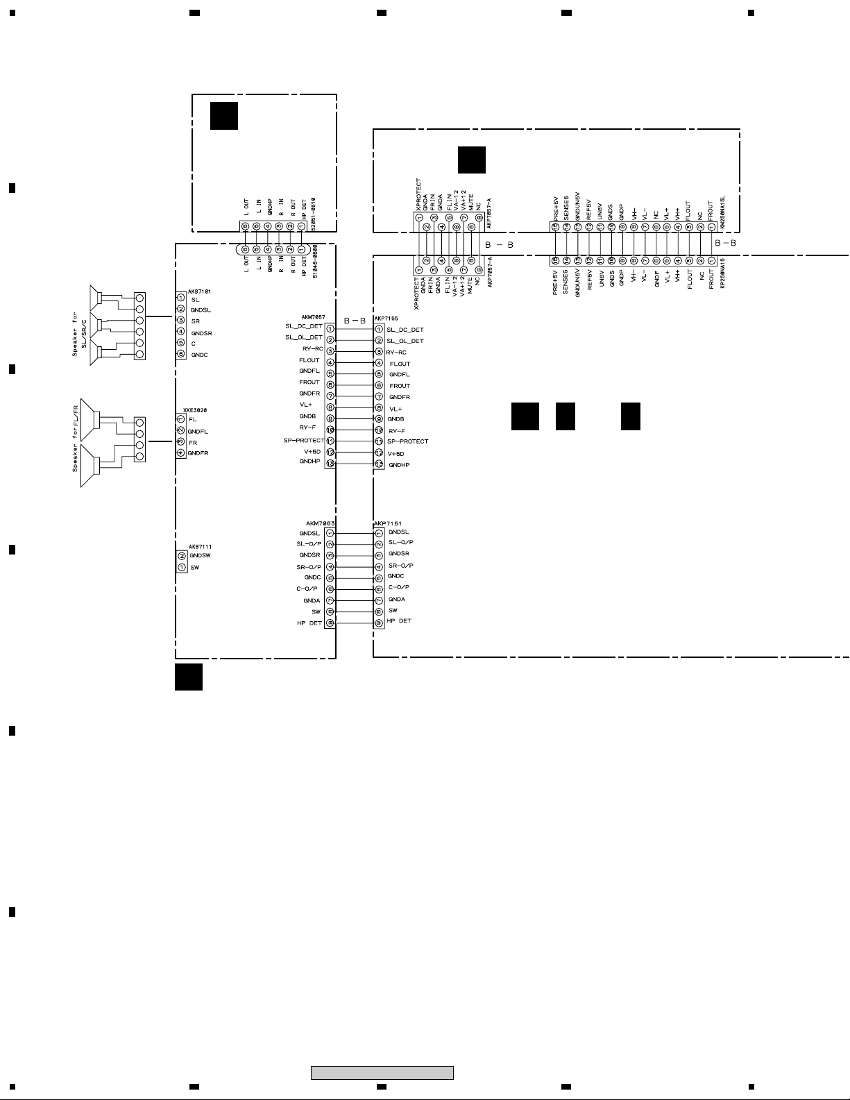
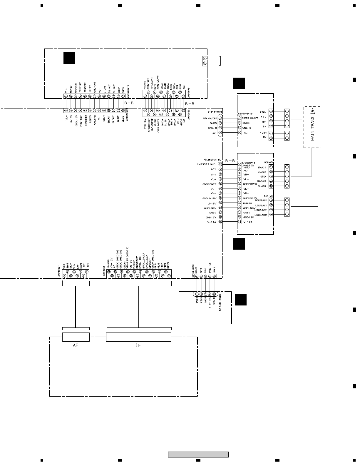
3. SCHEMATIC DIAGRAM
3.1 OVERALL WIRING DIAGRAM
A
E
HP ASSY
(XWZ3633)
23
VHVL AMP ASSY (AWU8024)
B
4
CN3004
J3309
B
JA3401
CN3305 CN3903
JA3303
CN3301
CN3101
CN3302
CN3102
()
A
A1/2 - A 2/2
E-VOL ASSY (XWZ3629)
C
CN3307 CN3902
JA3603
D
D
SP-TERMINAL ASSY
(XWZ3632)
Note : The connectors between E-VOL ASSY, SECONDARY ASSY, VHVL AMP ASSY and AMP REG FAN ASSY
E
F
(CN3003-CN3, CN3101-CN3301, CN3102-CN3302, CN3104-CN3502, CN3103-CN3501)
are board to board connectors. It is difficult to connect them.
Be sure to confirm the complete connections.
It may become the factor of trouble.
10
1234
M-EV51
5
Note : When ordering service parts, be sure to refer to "EXPLODED VIEWS and PARTS LIST" or "PCB PARTS LIST"
AMP REG FAN ASSY (AWU8025)
C
CN3502
CN3104
678
CN3651
FAN+B
FAN
MOTOR
FAN-B
PRIMARY ASSY
G
(XWZ3630)
CN3501
CN3103
CN2
T1
POWER
TRANSFORMER
XTS3064
A
B
SYSTEM
CABLE
CN3002CN3001
SYSTEM
CABLE
CN3901
J3651
J3906
CN3003
CN7
CN1
CN3
H
CN4
CN5
SECONDARY ASSY
(XWZ3631)
F
AMP DISPLAY ASSY
(XWZ3634)
C
D
E
XV-EV51
F
M-EV51
5
6
7
8
11
1
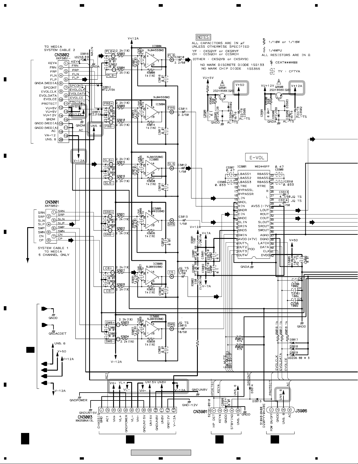
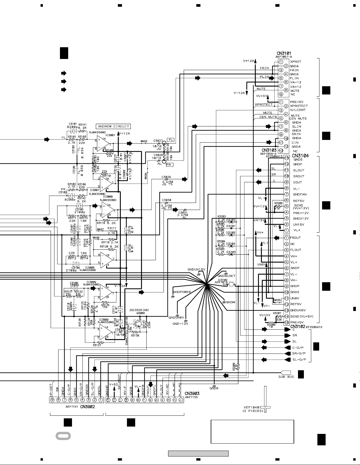
3.2 E-VOL ASSY (1/2)
A
23
4
(FL)
(FL)
B
(FL)
R3208
10
(FL)
To XV-EV51 IF (SYSTEM CABLE)
(SL)
C
(SL)
(SL)
(FL)
(SL)
(C)
(FL)
(C)
(SL)
(C)
D
To XV-EV51 AF
(C)
(SYSTEM CABLE)
(C)
0
E
A 2/2
R3099
F
A 1/2
12
H
CN3
F
J3651
M-EV51
1234
G
CN7
5
678
A
(FL)
(C)
A 1/2
(FL)
(SL)
(C)
E-VOL ASSY (XWZ3629)
: FL AUDIO SIGNAL ROUTE
: SL AUDIO SIGNAL ROUTE
: C AUDIO SIGNAL ROUTE
(SL)
(FL)
(SL)
(C)
(SL)
(SL)
(FL)
(FL)
(SL)
(C)
(SL)
(C)
CN3301
B
CN3501
C
CN3502
C
B
C
(SL)
(C)
2.2k
(C)
(SL)
2.7k
2.2k
(C)
(FL)
(FL)
(C)
(SL)
(C)
(SL)
(FL)
A 2/2
A 2/2
D
CN3302
B
E
CN3307
D
D
CN3305
: The power supply is shown with the marked box.
5
6
M-EV51
CAUTION : FOR CONTINUED PROTECTION
AGAINST RISK OF FIRE.
REPLACE ONLY WITH SAME TYPE
NO. 491005 FOR IC3102 MFD, BY
LITTELFUSE INC.
7
F
A 1/2
13
8
1
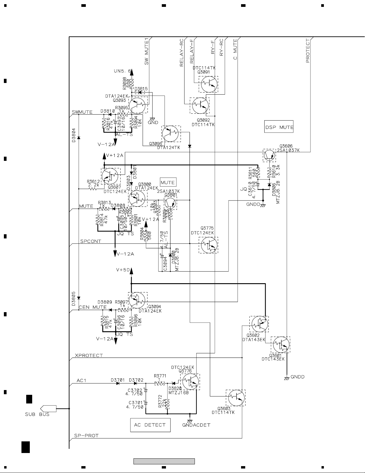
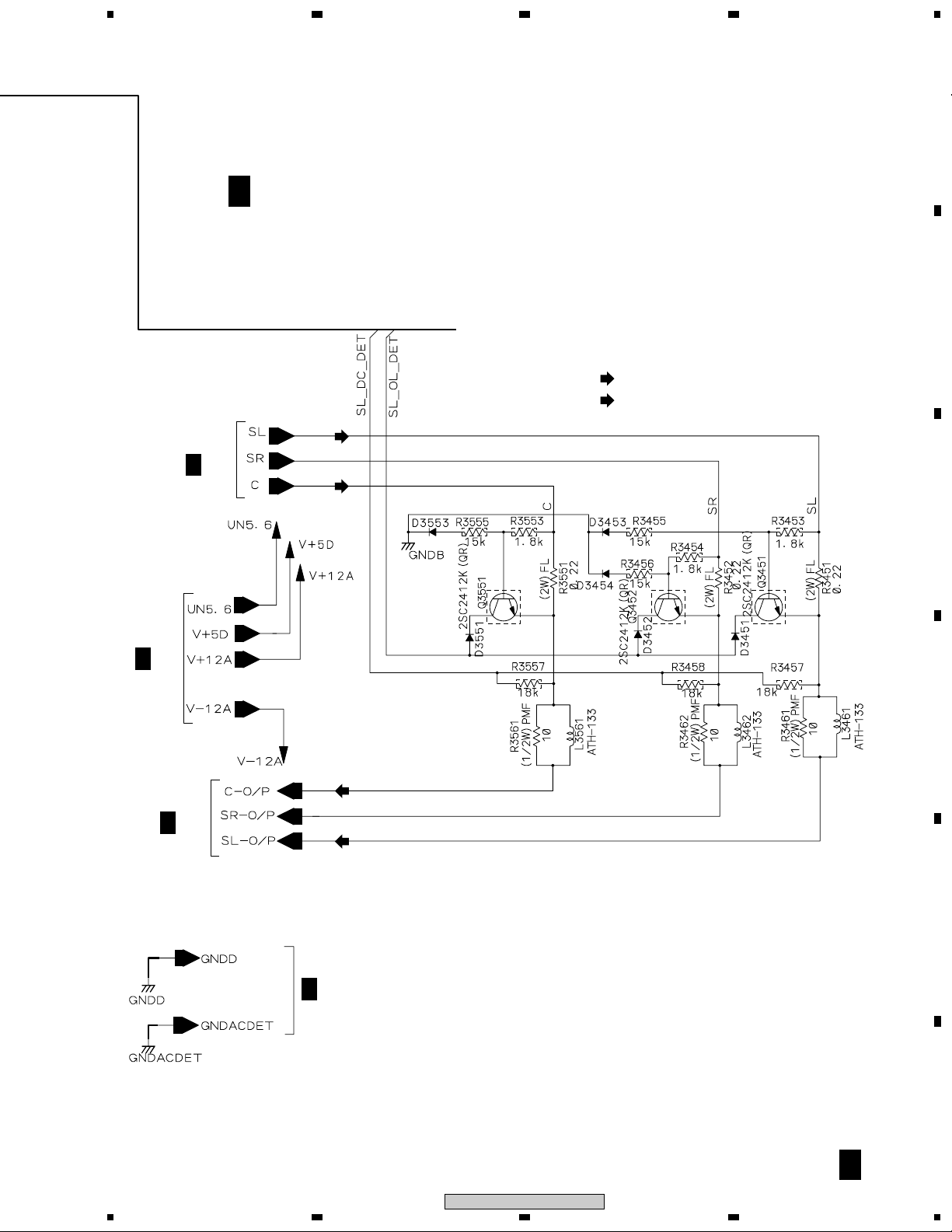
3.3 E-VOL ASSY (2/2)
A
B
23
UDZS5.1B
D3821
1SS133
4
C
D
E
A 1/2
F
A 2/2
14
1234
M-EV51
5
678
A
A 1/2
A 2/2
E-VOL ASSY (XWZ3629)
(SL)
(C)
(SL)
: SL AUDIO SIGNAL ROUTE
(C)
: C AUDIO SIGNAL ROUTE
B
C
A 1/2
A 1/2
D
(C)
(SL)
E
A 1/2
F
A 2/2
M-EV51
5
6
7
8
15
 Loading...