


ORDER NO.
RRV2171
MINI DISC RECORDER
MJ-HX55
MJ-HX33
MJ-HX77
THIS MANUAL IS APPLICABLE TO THE FOLLOWING MODEL(S) AND TYPE(S).
Type |
|
Model No. |
|
Power Requirement |
Remarks |
|
|
|
|
||||
MJ-HX55 |
MJ-HX33 |
MJ-HX77 |
||||
|
|
|
||||
|
|
|
|
|
|
|
ZLXCN |
à |
à |
à |
DC power supplied from other system component |
|
|
|
|
|
|
|
|
¦ This service manual should be used together with the following manual(s):
Model No. |
Order No. |
Remarks |
MJ-HX700/ZVYXCN RRV2134
 These products are component of systems.
 This product does not operate normally by itself. Please connect it to the CD RECEIVER SYSTEM, for adjustment and operation inspection. Otherwise damage may result.
 System Component Table
Component |
|
Model No. |
|
Remarks |
|
|
|
|
|||
X-HX55 |
X-HX33 |
X-HX77 |
|||
|
|
||||
|
|
|
|
|
|
CD RECEIVER AMPLIFIER |
XC-HX55 |
XC-HX33 |
XC-HX77 |
|
|
|
|
|
|
|
|
SPEAKER SYSTEM( L ch, R ch ) |
S-HX55-LR |
S-HX33-L, -R |
S-HX77-LR |
|
|
|
|
|
|
|
|
MD RECORDER |
MJ-HX55 |
MJ-HX33 |
MJ-HX77 |
This manual |
|
|
|
|
|
|
PIONEER CORPORATION 4-1, Meguro 1-Chome, Meguro-ku, Tokyo 153-8654, Japan
PIONEER ELECTRONICS SERVICE, INC. P.O. Box 1760, Long Beach, CA 90801-1760, U.S.A.
PIONEER ELECTRONIC (EUROPE) N.V. Haven 1087, Keetberglaan 1, 9120 Melsele, Belgium
PIONEER ELECTRONICS ASIACENTRE PTE. LTD. 253 Allexandra Road, #04-01, Singapore 159936
 PIONEER CORPORATION 1999
T–ZZR JULY 1999 Printed in Japan
MJ-HX55, MJ-HX33, MJ-HX77
7 CONTRAST OF MISCELLANEOUS PARTS
NOTES : Ö Parts marked by “ NSP ” are generally unavailable because they are not in our Master Spare Parts List.
ÖThe  mark found on some component parts indicates the importance of the safety factor of the part. Therefore, when replacing, be sure to use parts of identical designation.
ÖScrew adjacent to °mark on the product are used for disassembly.
ÖReference Nos. indicate the pages and Nos. in the service manual for the base model.
 CONTRAST TABLE
MJ-HX55/ZLXCN, MJ-HX33/ZLXCN, MJ-HX77/ZLXCN and MJ-HX700/ZVYXCN are constructed the same except
for the following :
Ref. |
|
|
|
Part No. |
|
|
||
Mark |
Symbol and Description |
|
|
|
|
Remarks |
||
MJ-HX700 |
MJ-HX55 |
MJ-HX33 |
MJ-HX77 |
|||||
No. |
||||||||
|
|
|
|
|
|
|
||
|
|
|
/ZVYXCN |
/ZLXCN |
/ZLXCN |
/ZLXCN |
|
|
|
|
PACKING |
|
|
|
|
|
|
P3-3 |
|
Display Carton |
66679-70 |
66679-55L |
66679-33L |
66679-77L |
|
|
P3-6 |
|
Sound Scape MD |
AFB7011 |
AFB7005 |
AFB7003 |
AFB7011 |
|
|
|
|
POS Code Seal |
66668-M70 |
66668-M55 |
66668-M33 |
66668-M77 |
No.1 |
|
|
|
EXTERIOR |
|
|
|
|
|
|
P5-1 |
NSP |
Front Cover (A) |
66714-K7M |
66714-05M |
Not used |
66714-K7M |
|
|
|
|
Front Cover (B) |
Not used |
Not used |
66715-03M |
Not used |
|
|
P5-2 |
NSP |
Front Door (A) |
66708-K7M |
66708-05M |
Not used |
66708-K7M |
|
|
|
|
Front Door (B) |
Not used |
Not used |
66709-03M |
Not used |
|
|
P5-3 |
|
Button B (MD) |
66717-K7M |
66717-05M |
66717-03M |
66717-K7M |
|
|
P5-10 |
|
MD Front Case |
66702-K7 |
66702-05 |
66702-03 |
66702-K7 |
|
|
P5-11 |
|
Button D (REC) |
66719-K7R |
66719-05R |
66719-03R |
66719-K7R |
|
|
P5-19 |
|
Eject Button |
66721-K7 |
66721-05 |
66721-03 |
66721-K7 |
|
|
P5-20 |
|
Button C (MD EDIT) |
66718-K7ME |
66718-05ME |
66718-03ME |
66718-K7ME |
|
|
P5-24 |
|
Inner Panel (MD) |
66711-K7M |
66711-05M |
66711-03M |
66711-K7M |
|
|
P5-36 |
|
Leg Rubber (A) |
66758-01 |
66758-01 |
Not used |
66758-01 |
|
|
|
|
Leg Rubber (B) |
Not used |
Not used |
66759-02 |
Not used |
|
|
P5-37 |
|
Foot (A) |
66722-K7 |
66722-05 |
Not used |
66722-K7 |
|
|
|
|
Foot (B) |
Not used |
Not used |
66723-03 |
Not used |
|
|
P5-38 |
|
MD Rear Case |
66704-K7 |
66704-05 |
66704-03 |
66704-K7 |
|
|
P5-46 |
|
Back Plate (MD) |
66762-70 |
66762-MJ55 |
66762-MJ33 |
66762-MJ77 |
|
|
P5-47 |
|
Front Door A Assy (MD) |
10000-K7M |
10000-05M |
Not used |
10000-K7M |
|
|
|
|
Front Door B Assy (MD) |
Not used |
Not used |
10100-03M |
Not used |
|
|
|
|
|
|
|
|
|
|
|
Note : • The numbers in the remarks column correspond to the numbers on the exploded diagram. Refer to “EXPLDED VIEWS”
 EXPLDED VIEWS
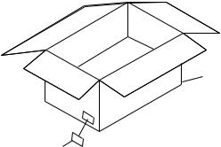
 PACKING SECTION
Front Side |
Display Carton |
|
No.1
2

ORDER NO.
RRV2134
MINI DISC RECORDER
MJ-HX5000
MJ-HX3000
MJ-HX2000
MJ-HX700
THIS MANUAL IS APPLICABLE TO THE FOLLOWING MODEL(S) AND TYPE(S).
Type |
|
|
Model |
|
Power Requirement |
Remarks |
||
|
|
|
|
|
||||
MJ-HX5000 |
MJ-HX3000 |
MJ-HX2000 |
MJ-HX700 |
|||||
|
|
|
||||||
|
|
|
|
|
|
|
|
|
ZUCXCN |
à |
à |
|
à |
— |
DC power supplied from other system component |
|
|
|
|
|
|
|
|
|
|
|
ZUCXCN1 |
à |
à |
|
à |
— |
DC power supplied from other system component |
|
|
|
|
|
|
|
|
|
|
|
ZVYXCN |
— |
— |
|
— |
à |
DC power supplied from other system component |
|
|
|
|
|
|
|
|
|
|
|
¦ ZUCXCN type and ZUCXCN1 type are constructed the same.
 These products are component of systems.
 This product does not operate normally by itself. Please connect it to the CD RECEIVER SYSTEM, for adjustment and operation inspection. Otherwise damage may result.
CONTENTS
1. SAFETY INFORMATION .................................... |
2 |
7. GENERAL INFORMATION |
28 |
|
2. EXPLODED VIEWS AND PARTS LIST |
3 |
|||
7.1 DIAGNOSIS |
28 |
|||
3. BLOCK DIAGRAM AND SCHEMATIC DIAGRAM 8 |
||||
7.2 PARTS |
30 |
|||
4. PCB CONNECTION DIAGRAM |
19 |
|||
8. PANEL FACILITIES AND SPECIFICATIONS |
|
|||
5. PCB PARTS LIST |
26 |
|
||
|
32 |
|||
6. ADJUSTMENT |
28 |
................................................................... |
||
|
|
|||
PIONEER ELECTRONIC CORPORATION 4-1, Meguro 1-Chome, Meguro-ku, Tokyo 153-8654, Japan PIONEER ELECTRONICS SERVICE, INC. P.O. Box 1760, Long Beach, CA 90801-1760, U.S.A.
PIONEER ELECTRONIC (EUROPE) N.V. Haven 1087, Keetberglaan 1, 9120 Melsele, Belgium PIONEER ELECTRONICS ASIACENTRE PTE. LTD. 253 Alexandra Road, #04-01, Singapore 159936
 PIONEER ELECTRONIC CORPORATION 1999
T–ZZR MAY 1999 Printed in Japan

MJ-HX5000, MJ-HX3000, MJ-HX2000, MJ-HX700
1. SAFETY INFORMATION
This service manual is intended for qualified service technicians; it is not meant for the casual do-it-yourselfer. Qualified technicians have the necessary test equipment and tools, and have been trained to properly and safely repair complex products such as those covered by this manual.
Improperly performed repairs can adversely affect the safety and reliability of the product and may void the warranty. If you are not qualified to perform the repair of this product properly and safely, you should not risk trying to do so and refer the repair to a qualified service technician.
WARNING
This product contains lead in solder and certain electrical parts contain chemicals which are known to the state of California to
cause cancer, birth defects or other reproductive harm.
Health & Safety Code Section 25249.6 – Proposition 65
|
IMPORTANT |
|
|
|
|
|
|
|
|
|
|
|
|
|
|
|
|
|
|
|
THIS PIONEER APPARATUS CONTAINS |
|
|
LASER DIODE CHARACTERISTICS |
|
||
|
|
|
||||
LASER OF CLASS 1. |
|
|
|
|
||
|
MAXIMUM OUTPUT POWER: 5 mw |
|||||
SERVICING OPERATION OF THE APPARATUS |
|
WAVELENGTH: 780 – 785 nm |
||||
S H O U L D B E D O N E B Y A S P E C I A L L Y |
|
|
|
|
||
|
|
|
|
|||
INSTRUCTED PERSON. |
|
|
|
|
||
|
|
|
|
|
|
|
LABEL CHECK
Excpet for MJ-HX700
MJ-HX700 type Only
MJ-HX700 type Only
2
MJ-HX5000, MJ-HX3000, MJ-HX2000, MJ-HX700
2. EXPLODED VIEWS AND PARTS LIST
NOTES : Ö Parts marked by “ NSP ” are generally unavailable because they are not in our Master Spare Parts List.
ÖThe  mark found on some component parts indicates the importance of the safety factor of the part. Therefore, when replacing, be sure to use parts of identical designation.
ÖScrew adjacent to °mark on the product are used for disassembly.
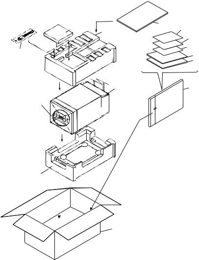
2.1PACKING
6 |
|
13 |
|
|
|
|
|
|
|
|
|
1 |
14 |
|
|
|
|
|
|
||||
|
|
|
|
|
|
|
|
|
|
|
|
|
|
|
12 |
|
|
|
|
|
|||
5 |
|
|
10 |
|
|
|
|
|
|||
|
|
9 |
|
|
|
|
|
||||
|
|
|
|
|
|
|
|
||||
|
|
|
8 |
|
|
|
|
|
|||
|
|
4 |
11 |
|
|
|
|
|
|||
7 |
|
|
|
|
|
|
|
|
|
|
|
|
|
|
|
(1)PACKING PARTS LIST |
|
|
|||||
|
|
|
|
Mark No. |
|
Description |
Parts No. |
||||
|
|
|
|
|
|
|
|
|
|
|
|
|
|
|
|
|
|
|
|
|
|
|
|
|
|
|
1 |
|
Polyfoam (TOP) |
66680 |
|
||||
|
|
|
2 |
|
Polyfoam (BOTTOM) |
66681 |
|
||||
|
|
|
3 |
|
Display Carton |
See Contrast table (2) |
|||||
|
|
|
4 |
|
Mirormat Mat(380x300x0.5) |
66694 |
|
||||
2 |
|
|
5 |
|
Exclusive use CD-MD Cable |
60233 |
|
||||
|
|
|
|
|
|
|
(L=1.0 m) |
|
|
||
|
|
|
|
|
|
|
|
|
|
||
|
|
|
6 |
|
Sound Scape MD |
AFB7011-A |
|||||
|
|
|
7 |
|
MD RECORDER |
See Contrast table (2) |
|||||
|
|
|
8 |
|
Operating Instructions (English) |
66780-MDU |
|||||
|
|
|
8 |
|
Operating Instructions (French) |
66780-MDF |
|||||
|
|
3 |
9 |
|
Operating Instructions |
See Contrast table (2) |
|||||
|
|
10 |
|
Guarantee Card |
See Contrast table (2) |
||||||
|
|
|
|
||||||||
|
|
|
11 |
|
Polyethylene Bag |
53117 |
|
||||
|
|
|
|
|
|
|
(0.03 × 200 × 300) |
|
|
|
|
|
|
|
12 |
|
Initial Instruction Manual |
66783 |
|
||||
|
|
|
13 |
|
Carton Sheet C |
66669 |
|
||||
|
|
|
14 |
|
Safety Directions |
See Contrast table (2) |
|||||
(2) CONTRAST TABLE
MJ-HX5000, MJ-HX3000, MJ-HX2000 and MJ-HX700 are constructed the same except for the following:
Mark |
No. |
Symbol and Description |
|
Part No. |
|
Remarks |
||
MJ-HX5000 |
MJ-HX3000 |
MJ-HX2000 |
MJ-HX700 |
|||||
|
|
|
|
|||||
|
|
|
|
|
|
|
|
|
|
3 |
Display Carton |
66679-50U |
66679-30U |
66679-20U |
66679-70 |
|
|
NSP |
7 |
MD RECORDER |
MJ-HX5000 |
MJ-HX3000 |
MJ-HX2000 |
MJ-HX700 |
|
|
|
|
|
/ZUCXCN |
/ZUCXCN |
/ZUCXCN |
/ZVYXCN |
|
|
|
9 |
Operating Instructions (German) |
Not used |
Not used |
Not used |
66780-MDG |
|
|
|
10 |
Guarantee Card |
66688-U |
66688-U |
66688-U |
66688-Y/N |
|
|
|
14 |
Safety Directions |
66784-50U |
66784-30U |
66784-20U |
66784-70V |
|
|
|
|
|
|
|
|
|
|
|
3
MJ-HX5000, MJ-HX3000, MJ-HX2000, MJ-HX700
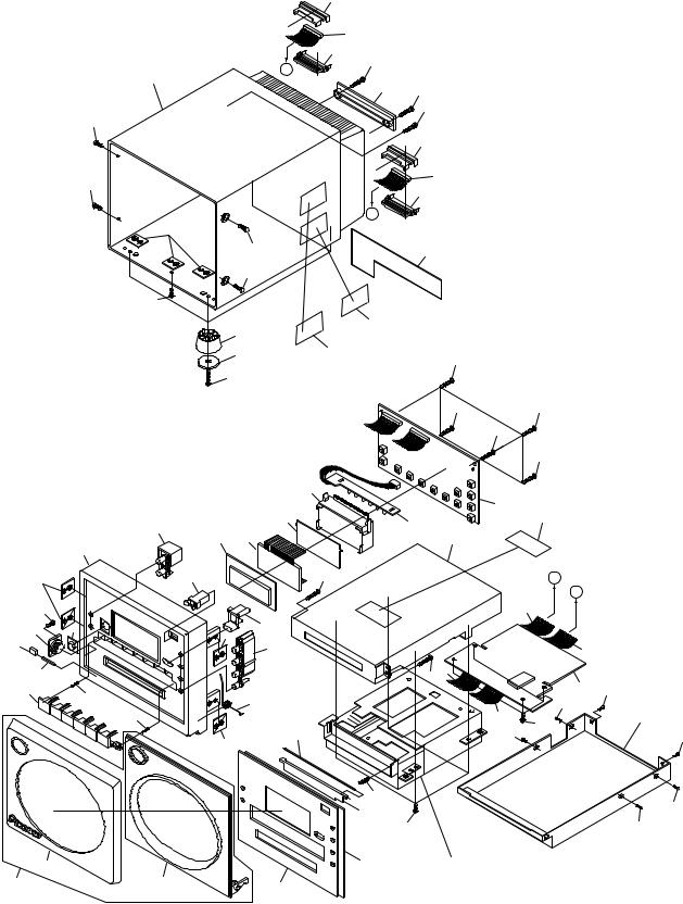
2.2 EXTERIOR |
|
|
39 |
|
|
|
|
|
|
|
|
|
40 |
|
|
|
|
|
|
|
|
41 |
|
|
|
|
|
|
|
B |
8 |
|
|
|
|
|
|
38 |
|
|
|
|
|
|
|
|
|
42 |
8 |
|
|
|
|
|
|
|
|
|
|
|
||
|
|
|
|
|
|
|
|
|
|
|
|
|
|
8 |
|
|
|
|
32 |
|
|
|
|
|
|
|
|
|
|
|
|
43 |
|
|
|
|
32 |
|
|
|
44 |
|
|
|
|
|
|
|
45 |
|
|
|
|
|
|
|
|
|
|
|
|
|
|
|
|
|
A |
|
|
|
|
|
|
9 |
|
|
|
|
|
|
|
|
|
32 |
|
46 |
|
|
|
|
|
|
32 |
|
|
|
|
|
|
|
32 |
|
|
|
|
|
|
|
|
|
37 |
51 |
|
|
|
|
|
|
|
|
|
|
|
|
|
|
|
|
36 |
52 |
8 |
|
|
|
|
|
|
|
|
|
|
||
|
|
|
|
|
|
|
|
|
|
|
|
35 |
|
|
|
|
|
|
|
|
|
|
8 |
|
8 |
|
|
|
|
|
|
|
8 |
|
|
|
|
|
|
|
|
|
8 |
|
|
|
|
15 |
|
|
|
|
|
|
|
|
|
|
|
17 |
|
|
|
|
11 |
14 |
|
16 |
|
53 |
|
|
|
|
|
|
|
|
||
|
10 |
12 |
13 |
|
31 |
|
|
|
|
|
|
|
|
|
|
|
|
9 |
|
18 |
|
8 |
|
|
A |
|
|
|
|
|
|
|
|
B |
|
8 |
|
|
|
|
|
|
40 |
|
7 |
4 |
|
19 |
|
|
|
|
|
|
|
9 |
|
|
|
|
|
|
5 |
|
|
|
|
|
|
|
|
|
|
20 |
|
|
|
44 |
|
|
6 |
|
|
|
|
50 |
|
|
|
|
|
|
|
8 |
|
|
|
|
3 |
|
|
|
|
|
33 |
34 |
|
23 |
|
22 |
|
|
|
|||
|
|
|
|
|
34 |
|
||
|
|
23 |
|
|
|
|
||
|
|
|
|
|
49 |
29 |
|
|
|
|
|
26 |
|
|
34 |
|
|
|
|
|
|
|
|
|
||
|
|
|
9 |
|
|
|
|
|
|
|
|
|
27 |
|
|
|
|
|
|
|
|
25 |
28 |
|
|
|
|
|
|
|
|
|
|
|
|
1 |
|
|
|
48 |
21 |
|
|
|
47 |
|
2 |
24 |
|
Refer to "2.3 MD MECHA. (1/2)" |
|||
|
|
|
"2.4 MD MECHA. (2/2)" |
|||||
|
|
|
|
|
||||
30
34
34
34
4
MJ-HX5000, MJ-HX3000, MJ-HX2000, MJ-HX700
(1) EXTERIOR PARTS LIST
Mark |
No. |
|
Description |
|
Parts No. |
Mark |
No. |
|
Description |
|
Parts No. |
|||||
|
|
|
|
|
|
|
|
|
|
|
|
|
|
|
|
|
|
|
|
|
|
|
|
|
|
|
|
|
|
|
|
|
|
|
|
|
|
|
|
|
|
|
|
|
|
|
|
|
||
|
|
|
|
|
|
|
|
|
|
26 |
|
MD Door Shaft |
66750 |
|
||
NSP |
1 |
|
Front Cover A, B (MD) |
See Contrast table (2) |
|
|
|
|
||||||||
NSP |
2 |
|
Front Door A, B (MD) |
See Contrast table (2) |
|
|
27 |
|
MD Door Spring |
66751 |
|
|||||
|
|
3 |
|
Button B (MD) |
See Contrast table (2) |
|
|
28 |
|
Screw PAN M3x6 |
PMZ30P060FZK |
|||||
|
|
4 |
|
Lens |
66734-MD |
|
|
29 |
|
Screw BIND TAPP. M3x6 |
BMZ30P060FZK |
|||||
|
|
5 |
|
Cushion A |
66795 |
|
|
|
30 |
|
Shield Case (Bottom) |
66739 |
|
|||
|
|
6 |
|
Door Shaft A |
66746 |
|
|
|
31 |
|
Shield Case (Up) |
66738 |
|
|||
|
|
7 |
|
Dumper Gear |
60227 |
|
|
|
32 |
|
Screw PLAT M3x6 |
CMZ30P060FNI |
||||
|
|
8 |
|
Screw PAN TAPP. T3x10 |
PMZ30P100FNI |
|
|
33 |
|
MD COMBI PCB Assy |
66785B |
|||||
|
|
9 |
|
Plate Nut |
66741 |
|
|
|
|
|
(AD/DA PCB) |
|
|
|
||
|
|
10 |
|
MD Front Case |
See Contrast table (2) |
|
|
34 |
|
Screw PAN M2x4 |
PMZ20P040FZK |
|||||
|
|
|
|
|
|
|
|
|
|
35 |
|
Screw PAN M3x10 |
PBZ30P100FMC |
|||
|
|
11 |
|
Button D (REC) |
See Contrast table (2) |
|
|
|
|
|
|
|
|
|
||
|
|
12 |
|
LCD Window |
66735 |
|
|
|
36 |
|
Leg Rubber (A, B) |
See Contrast table (2) |
||||
|
|
13 |
|
LCD Assy |
52715 |
|
|
|
37 |
|
Foot (A, B) |
See Contrast table (2) |
||||
|
|
14 |
|
LCD Sheet |
66756 |
|
|
|
38 |
|
MD Rear Case |
See Contrast table (2) |
||||
|
|
15 |
|
LCD Holder |
66727 |
|
|
|
39 |
|
12P |
Connector Holder A |
66728 |
|
||
|
|
|
|
|
|
|
|
NSP |
40 |
|
12P |
Connector Assy |
66763 |
|
||
|
|
16 |
|
MD COMBI PCB Assy |
66785C |
|
|
|
|
|
|
|
|
|
||
|
|
|
|
(LED PCB) |
|
|
|
|
|
41 |
|
12P |
Connector Holder B |
66729 |
|
|
|
|
17 |
|
MD COMBI PCB Assy |
66785A |
|
|
42 |
|
Wire Clamper |
66726 |
|
||||
|
|
|
|
(FRONT PCB) |
|
|
|
|
|
43 |
|
10P |
Connector Holder A |
66730 |
|
|
|
|
18 |
|
Push Door Lock |
60226 |
|
NSP |
44 |
|
10P |
Connector Assy |
66778 |
|
|||
|
|
19 |
|
Eject Button |
See Contrast table (2) |
|
|
45 |
|
10P |
Connector Holder B |
66731 |
|
|||
|
|
20 |
|
Button C (MD EDIT) |
See Contrast table (2) |
|
|
|
|
|
|
|
|
|
||
|
|
|
|
|
|
|
|
|
|
46 |
|
Back Plate (MD) |
See Contrast table (2) |
|||
|
|
21 |
|
MD Mechanism Assy |
61416 |
|
|
|
47 |
|
Front Door Assy A,B (MD) |
See Contrast table (2) |
||||
|
|
22 |
|
Front Door Spring |
66748 |
|
|
|
48 |
|
Panel Tape B |
66761 |
|
|||
|
|
23 |
|
Screw PAN TAPP. T2x8 |
PBZ20P080FMC |
|
|
49 |
|
16P |
FFC (SUMI Card) |
66775 |
|
|||
|
|
24 |
|
Inner Panel (MD) |
See Contrast table (2) |
|
|
50 |
|
19P |
FFC (SUMI Card) |
66776 |
|
|||
|
|
25 |
|
MD Door |
66732 |
|
|
|
|
|
|
|
|
|
|
|
|
|
|
|
|
|
|
|
|
|
51 |
|
Label Plate (CAUTION) |
66690I |
|||
|
|
|
|
|
|
|
|
|
|
52 |
|
Label Plate |
See Contrast table (2) |
|||
|
|
|
|
|
|
|
|
|
|
53 |
|
Label Plate (MD Caution A) |
See Contrast table (2) |
|||
(2) CONTRAST TABLE
MJ-HX5000, MJ-HX3000, MJ-HX2000 and MJ-HX700 are constructed the same except for the following:
Mark |
No. |
Symbol and Description |
|
Part No. |
|
Remarks |
||
MJ-HX5000 |
MJ-HX3000 |
MJ-HX2000 |
MJ-HX700 |
|||||
|
|
|
|
|||||
|
|
|
|
|
|
|
|
|
NSP |
1 |
Front Cover (A, B) |
66714-05M |
66715-03M |
66714-02M |
66714-K7M |
|
|
NSP |
2 |
Front Door (A, B) |
66708-05M |
66709-03M |
66708-02M |
66708-K7M |
|
|
|
3 |
Button B (MD) |
66717-05M |
66717-03M |
66717-02M |
66717-K7M |
|
|
|
10 |
MD Front Case |
66702-05 |
66702-03 |
66702-02 |
66702-K7 |
|
|
|
11 |
Button D (REC) |
66719-05R |
66719-03R |
66719-02R |
66719-K7R |
|
|
|
19 |
Eject Button |
66721-05 |
66721-03 |
66721-02 |
66721-K7 |
|
|
|
20 |
Button C (MD EDIT) |
66718-05ME |
66718-03ME |
66718-02ME |
66718-K7ME |
|
|
|
24 |
Inner Panel (MD) |
66711-05M |
66711-03M |
66711-02M |
66711-K7M |
|
|
|
36 |
Leg Rubber (A, B) |
66758-01 |
66758-02 |
66758-02 |
66758-01 |
|
|
|
37 |
Foot (A, B) |
66722-05 |
66723-03 |
66723-02 |
66722-K7 |
|
|
|
38 |
MD Rear Case |
66704-05 |
66704-03 |
66704-02 |
66704-K7 |
|
|
|
46 |
Back Plate (MD) |
66762-50U |
66762-30U |
66762-20U |
66762-70 |
|
|
|
47 |
Front Door Assy (MD) |
10000-05M |
10000-03M |
10000-02M |
10000-K7M |
|
|
|
52 |
Label Plate |
66690B |
66690B |
66690B |
66690E |
|
|
|
53 |
Label Plate (MD Caution A) |
Not used |
Not used |
Not used |
66690A |
|
|
|
|
|
|
|
|
|
|
|
5
MJ-HX5000, MJ-HX3000, MJ-HX2000, MJ-HX700
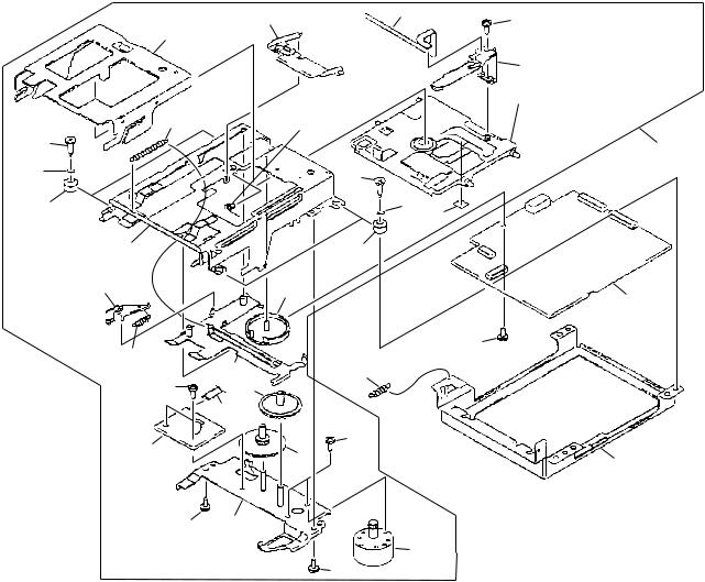
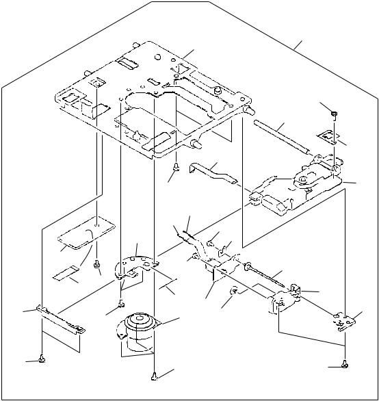
2.3 MD MECHA. (1/2 : LOADING ASSY)
13
12
11
19
15
14
16 |
17 |
13
12
22
20
21
Refer to "2.4 MD MECHA. (2/2 : MECHA ASSY)
33
10 |
|
11 |
9 |
|
18 |
|
|
23 |
|
|
24 |
8 |
|
|
|
7 |
26 |
32 |
|
|
|
6 |
|
|
4 |
|
 31 3
31 3
5
27
2 1
30
2
¦ MD MECHA. (1/2:LOADING ASSY) PARTS LIST
Mark No. |
|
Description |
|
Parts No. |
|
Mark No. |
|
Description |
|
Parts No. |
||||
|
|
|
|
|
|
|
|
|
|
|
|
|
|
|
|
|
|
|
|
|
|
|
|
|
|
|
|
|
|
1 |
|
Motor Plate Assy |
X-2646-247-1 |
18 |
|
Mode Cam |
2-646-560-01 |
|||||||
2 |
|
Screw +P2.6x4.5 TYPE3 |
7-627-854-28 |
19 |
|
Head F.Wire Connection |
1-669-181-11 |
|||||||
3 |
|
L-SW Wire Connection Board |
1-668-261-11 |
20 |
|
Screw +P1.7x2.5TYPE2 |
2-627-529-01 |
|||||||
4 |
|
Connecton Wire (6P) |
1-783-386-11 |
21 |
|
MD Head |
1-500-518-12 |
|||||||
5 |
|
Gear (AW B) |
2-646-555-02 |
22 |
|
Sheet |
2-646-549-02 |
|||||||
6 |
|
Gear (AW A) |
2-646-554-01 |
23 |
|
MD MOUNT ASSY |
A-4917-020-A |
|||||||
7 |
|
Slot Frame Assy |
X-2646-249-2 |
24 |
|
Screw |
2-643-228-01 |
|||||||
8 |
|
Lifter Spring (Slot Arm) |
2-646-563-01 |
25 |
|
• • • • • |
|
|
||||||
9 |
|
Slot Arm |
2-646-556-01 |
26 |
|
Lifter Spring (Door Arm) |
2-646-545-01 |
|||||||
10 |
|
Load Frame Assy |
X-2646-248-2 |
27 |
|
Main Frame |
2-646-547-02 |
|||||||
11 |
|
lnsulator |
2-646-548-01 |
28 |
|
• • • • • |
|
|
||||||
12 |
|
W2.6,MIDDLE |
7-688-002-11 |
29 |
|
• • • • • |
|
|
||||||
13 |
|
Screw |
4-628-167-01 |
30 |
|
Loading Motor Assy |
X-2626-328-1 |
|||||||
14 |
|
Slid Frame |
2-646-557-01 |
31 |
|
Screw +P1.7x1.8TYP.3 |
7-627-852-38 |
|||||||
15 |
|
Head Arm |
2-646-559-01 |
32 |
|
Screw +P2x3 TYP.3 |
7-627-853-37 |
|||||||
16 |
|
Lifter Spring (Slot Frame) |
2-646-562-01 |
33 |
|
Loading Assy |
A-4912-117-A |
|||||||
17 |
|
Coil Spring (Head Arm) |
2-646-561-01 |
|
|
|
|
|
|
|
|
|||
6
MJ-HX5000, MJ-HX3000, MJ-HX2000, MJ-HX700
2.4 MD MECHA. (2/2 : MECHA ASSY)
23
6
|
|
|
|
|
|
|
|
|
|
|
12 |
|
|
|
|
|
|
|
|
|
|
|
|
|
|
|
11 |
|
|
|
|
|
|
|
|
|
|
|
|
|
|
|
|
|
13 |
|
|
|
|
|
|
|
|
|
|
8 |
|
|
|
|
|
|
|
|
|
|
|
|
1 |
|
|
|
|
|
|
24 |
|||
|
|
|
|
|
|
|
|
|
|
|
|
|
|
||
|
|
|
|
|
9 |
|
|
|
|
|
|
|
|
||
|
|
|
|
|
10 |
|
|
|
|
|
|
|
|
|
|
|
|
|
|
|
|
|
|
15 |
|
|
|
|
|
|
|
|
|
|
|
|
7 |
|
14 |
|
|
|
|
|
|||
|
|
|
5 |
15 |
|
|
|
|
|
|
|
|
|||
|
|
|
|
|
|
|
|
20 |
|
|
|
||||
|
|
|
|
|
|
|
|
|
|
|
|
|
|
||
|
|
|
4 |
|
|
|
|
|
|
|
|
|
|
|
|
|
|
|
3 |
|
|
|
|
|
|
21 |
|
|
|
||
|
|
|
|
|
25 |
|
|
|
|
|
|
|
|||
|
|
|
|
|
|
|
|
|
|
|
|
|
|
||
|
|
|
2 |
16 |
|
|
|
|
|
22 |
|||||
|
|
|
|
|
|
17 |
|
|
|
|
|||||
|
|
|
|
|
|
|
|
|
|
|
|
|
|||
|
|
|
4 |
19 |
|
|
|
|
|
|
|
||||
|
|
|
|
|
|
|
|
|
|
|
|||||
|
|
|
1 |
18 |
|
|
|
1 |
|
|
|
||||
|
|
|
|
|
|
|
|
|
|
|
|||||
¦ MD MECHA. (2/2:MECHA ASSY) PARTS LIST |
|
|
|
|
|
|
|
|
|||||||
Mark No. |
|
Description |
|
Parts No. |
Mark No. |
|
Description |
|
|
Parts No. |
|||||
|
|
|
|
|
|
|
|
|
|
|
|
|
|
|
|
|
|
|
|
|
|
|
|
|
|
|
|
|
|
|
|
1 |
|
Screw +P1.4x3.5 TYPE3 |
2-627-404-01 |
|
16 |
|
SL Motor Assy |
|
|
X-2626-329-1 |
|||||
2 |
|
Guide |
2-646-453-01 |
|
17 |
|
Gear (MD) |
2-646-571-01 |
|||||||
3 |
|
Connecton Wire (7P) |
1-783-387-11 |
|
18 |
|
Screw +P1.7x4 TYPE3 |
7-627-852-18 |
|||||||
4 |
|
Screw +P1.4x1.8TYPE3 |
7-627-850-79 |
|
19 |
|
SP Motor Assy |
|
|
X-2626-327-1 |
|||||
5 |
|
D-SW MOUNT BOARD |
1-668-262-11 |
|
20 |
|
Lead Screw Assy |
|
|
X-2626-330-1 |
|||||
6 |
|
Servo Base |
2-646-575-01 |
|
21 |
|
Lead Holder Assy |
|
|
X-2626-331-1 |
|||||
7 |
|
SP Motor Holder |
2-646-566-01 |
|
22 |
|
Lead Holder (B) |
2-646-573-01 |
|||||||
8 |
|
OP Lead Wire |
1-669-180-11 |
|
23 |
|
Deck Mechanism Assy |
|
|
A-4912-118-A |
|||||
9 |
|
SL Motor Lead Wire |
1-783-318-11 |
|
24 |
|
MD MECHANISM ASSY |
|
|
KMS-260A |
|||||
10 |
|
SL Motor Lead Wire |
1-783-318-21 |
|
|
|
|
|
(KMS-260A) |
|
|
|
|||
|
|
|
|
|
|
|
|
25 |
|
SP Tension Spring |
2-646-564-01 |
||||
11 |
|
Guide Shaft |
2-646-452-01 |
|
|
|
|
|
|
|
|
|
|||
12 |
|
Screw +P1.4x1.4TYPE2 |
2-627-530-D1 |
|
|
|
|
|
|
|
|
||||
13 |
|
Rack (Insater) |
4-963-914-02 |
|
|
|
|
|
|
|
|
|
|||
14 |
|
Pulley Load plate |
2-646-567-01 |
|
|
|
|
|
|
|
|
|
|||
15 |
|
N0.0 Cross Screw |
2-627-431-01 |
|
|
|
|
|
|
|
|
|
|||
7
|
1 |
|
2 |
|
3 |
|
4 |
|
|
|
|
|
|
MJ-HX5000, MJ-HX3000, MJ-HX2000, MJ-HX700
|
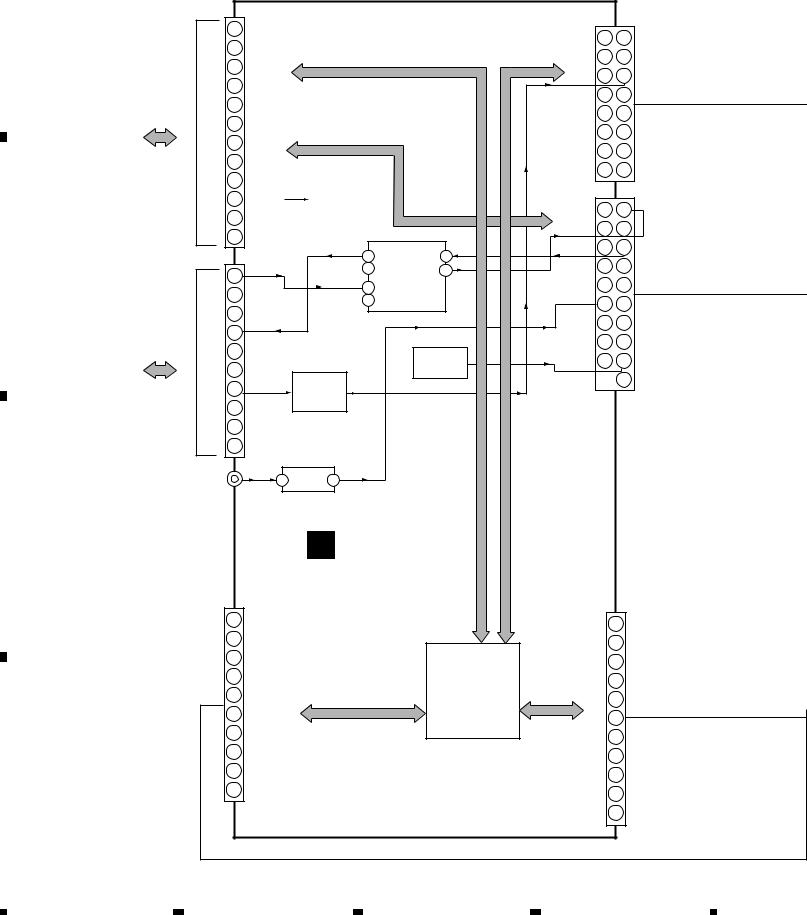
3. BLOCK DIAGRAM AND SCHEMATIC DIAGRAM |
|
|
|||||||||||
|
3.1 BLOCK DIAGRAM |
|
|
|
|
|
|
|
|
|
|
|
|
|
A |
PCB |
|
|
CN805 |
|
|
|
|
|
|
|
|
|
|
|
|
|
|
|
|
|
|
|
|
CN801 |
|
|||
|
|
1 |
CON |
|
|
|
|
|
|
|
|
|||
|
|
|
|
|
|
|
|
|
SYS3.3V |
2 |
1 |
|||
|
POWER |
CN301 |
3 |
SYSSO |
|
|
|
|
|
|
|
LEDO |
||
|
|
|
2 |
SYSSI |
|
|
|
|
|
|
|
STB |
4 |
3 |
|
|
|
|
|
|
|
|
|
|
|
|
VBAT |
||
|
|
|
4 |
SYSCLK |
|
|
|
|
|
|
|
AMUTE |
6 |
5 |
|
|
|
|
|
|
|
|
|
|
|
|
|||
|
|
RECEIVER |
|
|
|
|
|
|
DOWNPOWER |
XLATCH |
8 |
7 |
||
|
|
5 |
SUBCS |
|
|
|
|
|
|
|||||
|
|
|
|
|
|
|
|
|
|
|||||
|
|
|
|
|
|
|
|
|
|
DA RST |
10 |
9 |
||
|
|
|
6 |
SUBREQ |
|
|
|
|
|
|
|
RXD |
||
|
|
|
|
|
|
|
|
|
|
TXD |
12 |
11 |
||
|
|
|
|
|
|
|
|
|
|
|
|
|||
|
|
|
7 |
SUBRST |
|
|
|
|
|
|
|
RTS |
|
|
|
|
|
|
|
|
|
|
|
|
CTS |
14 |
13 |
||
|
|
|
8 |
COM+5V |
|
|
|
|
|
|
|
|||
|
|
|
|
|
|
|
|
|
|
|
16 |
15 |
||
|
|
CD |
9 |
COM GND |
|
|
|
|
|
|
|
EMPHASIS |
||
|
|
|
|
|
|
|
|
|
|
|
|
|||
|
|
10 |
MD+5V |
MD +5V |
|
|
|
|
|
CN804 |
|
|||
|
|
TO |
|
|
|
|
|
|
2 |
1 |
||||
|
|
11 |
MDGND |
|
|
|
|
|
|
|
|
|||
|
|
|
|
|
|
|
|
|
|
|
||||
|
|
|
|
|
|
|
|
|
|
|
4 |
3 |
||
|
|
|
12 |
CON |
|
|
|
|
|
|
|
ADDT |
||
|
|
|
|
|
|
|
|
|
|
|
6 |
5 |
||
|
|
|
|
|
|
MD |
19 |
|
15 |
MD |
|
|
||
|
PCB |
|
|
CN806 |
|
IC801 |
|
|
|
|
||||
B |
|
|
|
|
|
|
DADT |
8 |
7 |
|||||
|
|
REC L |
|
R ch 20 |
52186 |
12 |
|
|
||||||
|
|
|
|
|
|
|
|
|
|
|
|
|
|
|
|
TUNER |
CN101 |
1 |
|
|
MD REC |
|
(AK4518-VF-E2) |
|
|
DIN |
12 |
11 |
|
|
|
|
|
|
|
6 |
AD/DA CON. |
|
|
|
10 |
9 |
||
|
|
|
2 |
AU GND |
|
|
|
|
|
|||||
|
|
|
|
R ch 3 |
|
|
|
|
|
|
|
|||
|
|
|
|
|
|
|
|
|
|
|
|
|
||
|
|
RECEIVER |
3 |
AU+9V |
(2SA1037K, |
|
|
|
|
|
|
14 |
13 |
|
|
|
7 |
|
|
|
|
|
DOUT |
||||||
|
|
|
4 |
LCH |
|
|
|
|
|
|
|
|||
|
|
|
|
|
|
|
|
|
|
|
|
+5V |
16 |
15 |
|
|
|
5 |
AU GND |
|
|
|
|
IC802 |
|
|
+5V |
18 |
17 |
|
|
|
6 |
|
|
|
|
|
(TC7SU04F) |
|
|
|||
|
|
|
|
Q803 - Q807 |
|
|
X'TAL OSC. |
|
256FS |
|
19 |
|||
|
|
|
|
|
|
|
|
|
|
|
||||
|
|
CD |
|
|
2SC2412K) |
|
|
|
|
|
|
|
|
|
|
|
8 |
AU GND |
+3.3V REG. |
|
|
|
|
|
|
|
|
||
|
|
|
|
|
|
|
|
|
|
|
||||
|
|
TO |
9 |
B.LED+9V |
|
|
|
|
|
|
|
|
|
|
|
|
10 |
B.LEDGND |
|
|
|
|
|
|
|
|
|
|
|
|
EXCLUSIVE USE |
|
CN807 |
|
2 |
|
|
|
|
|
|
|
|
|
|
CD– MD |
|
1 |
IC803 |
|
|
|
|
|
|
|
|
||
|
TARMINAL |
|
|
|
|
|
|
|
|
|
|
|
|
|
|
CD |
|
|
|
|
|
|
|
|
|
|
|
|
|
C |
REC IN |
|
|
A AD/DA PCB |
|
|
|
|
|
|||||
|
|
|
|
|
|
|
|
|
|
|||||
|
|
|
|
|
|
ASSY |
|
|
|
|
|
|
||
|
|
|
|
CN802 |
|
|
|
|
|
|
|
CN803 |
|
|
|
|
|
1 |
AN0 |
|
|
|
|
|
|
|
DB7 |
1 |
|
|
|
|
|
|
|
|
|
|
|
|
|
|||
|
|
|
2 |
AN1 |
|
|
|
|
|
|
|
DB6 |
2 |
|
|
|
|
|
|
|
|
|
|
|
|
|
|||
|
|
|
3 |
AN2 |
|
|
|
|
|
|
|
DB5 |
3 |
|
|
|
|
|
|
|
|
|
|
|
|
|
|||
|
|
|
4 |
B.LED+9V |
|
|
|
|
|
IC800 |
|
DB4 |
4 |
|
|
|
|
|
|
|
|
|
|
52181 |
|
||||
|
|
|
5 |
B.LEDGND |
|
|
|
|
|
|
|
|
|
|
|
|
|
|
|
|
|
(CXP84632-1) |
|
DB3 |
5 |
||||
|
|
|
6 |
SCAPELED |
|
|
|
SUB. CPU |
|
DB2 |
6 |
|||
|
|
|
|
|
|
|
|
|
||||||
|
|
|
|
|
|
|
|
|
|
|
|
|||
|
|
|
7 |
BACKLEDY |
|
|
|
|
|
|
DB1 |
7 |
||
|
|
|
|
|
|
|
|
|
|
|
|
|||
|
|
|
8 |
BACKLEDG |
|
|
|
|
|
|
DB0 |
8 |
||
|
|
|
|
|
|
|
|
|
|
|
|
|||
|
|
|
9 |
GND |
|
|
|
|
|
|
|
|
E |
9 |
D |
|
|
|
|
|
|
|
|
|
|
|
|
||
|
|
10 |
+5V |
|
|
|
|
|
|
|
R/W |
10 |
||
|
|
|
|
|
|
|
|
|
|
|||||
|
|
|
|
|
|
|
|
|
|
|
|
|||
|
|
|
|
|
|
|
|
|
|
|
|
RS |
11 |
|
|
8 |
|
|
|
|
|
|
|
|
|
|
|
|
|
|
1 |
|
|
2 |
|
|
|
|
3 |
|
|
|
|
4 |

|
5 |
|
6 |
|
7 |
|
8 |
|
|
|
|
MJ-HX5000, MJ-HX3000, MJ-HX2000, MJ-HX700
|
|
CN103 |
|
|
|
|
|
|
|
|
|
|
|
|
CN106 |
|
|
|
|
|
|
|
11) |
||
2 |
|
1 |
|
|
AMUTE |
93 |
43, 36, 23, 20, 13, 8, |
|
|
|
|
|
|
CHACK IN |
1 |
|
1 |
|
|
|
|
||||
|
|
|
|
|
|
|
|
|
|
|
|
|
|
|
|
|
|
|
|||||||
|
|
|
|
|
|
|
|
|
|
|
|
|
|
|
|
|
|
|
|
|
|
|
|||
4 |
|
3 |
|
XLATCH |
90 |
|
|
|
CHACK IN |
6 |
|
|
|
|
|
|
2 |
|
2 |
PWBSW-L |
|
|
261-668-(1- |
||
|
|
|
|
|
|
|
|
|
|
|
|
|
|
ASSY |
|
||||||||||
6 |
|
5 |
|
|
DARST |
|
|
|
|
37 |
REC P |
|
|
|
|
|
3 |
|
3 |
|
|||||
|
|
|
83 |
|
|
|
PB P |
|
|
|
|
|
|
|
|
|
|
|
|||||||
|
|
|
|
|
EMP 70 |
|
|
μCOM |
38 |
|
|
|
|
|
|
|
|
|
|
|
|
|
|
||
|
|
|
|
|
|
|
|
|
|
|
|
|
|
REC P |
|
|
|
|
|
|
|
|
|||
8 |
|
7 |
|
|
CTS |
|
|
|
(IC201) |
|
|
|
|
|
|
|
4 |
|
4 |
|
|
|
|
|
|
|
|
|
60 |
|
RU8X12MF-0020 |
|
|
|
|
|
|
|
|
|
|
|
|
|
|||||||
10 |
9 |
|
|
RTS |
59 |
|
|
|
|
|
|
|
|
|
|
PB P |
5 |
|
5 |
|
|
|
|
|
|
|
|
TXD |
|
|
|
|
|
|
|
|
|
|
|
|
|
|
|
|
|
||||||
|
|
58 |
|
|
|
|
|
|
|
|
|
|
|
|
|
|
|
|
|
||||||
12 |
11 |
|
|
RXD |
57 |
|
|
|
LIMITIN 96 |
|
|
|
|
|
LIMITIN |
6 |
|
6 |
|
|
|
|
|
||
|
|
|
|
|
|
|
|
|
|
|
|
|
|
|
|
|
|
|
|
||||||
|
|
|
|
|
|
|
|
41–42, 32-33,12-16 |
|
|
|
|
|
|
|
|
|
|
|
|
|
|
|
||
14 |
13 |
|
|
|
|
|
|
|
|
|
|
C MD MOUNT |
CN105 |
|
|
|
|
|
|
|
|
||||
|
|
|
|
|
|
|
|
|
|
|
|
|
|
|
|
|
|
|
|
|
|||||
16 |
15 |
|
|
|
|
|
|
|
|
|
|
|
1 |
|
1 |
|
|
|
|
11) |
|||||
|
|
|
|
|
|
|
|
|
|
|
|
|
|
|
|
|
|
|
|
|
|
|
|||
CN102 |
|
|
|
|
|
|
|
|
|
|
|
ASSY |
|
|
|
2 |
|
2 |
|
|
|
|
|||
4 |
|
3 |
ADDT |
|
|
|
|
|
|
|
|
|
|
|
|
4 |
|
4 |
|
PWB |
|
|
262- - |
||
|
|
|
53 |
|
|
|
DADATA |
24 |
|
|
|
|
|
|
|
|
|
|
|||||||
2 |
|
1 |
|
|
|
|
|
|
|
DIN |
|
|
|
|
|
|
3 |
|
3 |
|
|
|
|
|
|
|
|
|
|
|
A2+3V |
|
1–9, 10–15 |
21 |
|
|
|
|
|
|
|
|
|
|
|
|
|
|
|
||
|
|
|
|
|
|
69 |
|
|
|
|
|
|
|
|
|
|
SPDL+ |
|
|
|
|
|
|
|
|
|
|
|
|
|
A2+3V |
|
|
|
|
|
|
|
|
|
|
|
|
|
|
|
|
|
-(1668 |
||
|
|
|
|
|
|
|
|
|
79–6783 |
|
|
|
|
|
|
|
|
|
|
SW-D |
ASSY |
||||
|
|
|
|
|
SRDR 91 |
|
CXD2652AR |
ADDATA |
|
|
|
|
|
|
|
|
|
|
|||||||
6 |
|
5 |
|
|
TRDR 85 |
|
|
DSSP |
|
|
|
|
|
|
|
SPDL- |
5 |
|
5 |
|
|
|
|
|
|
|
|
|
DADT |
|
TFDR |
86 |
|
|
& |
|
|
|
|
|
|
|
|
|
|
|
|
|
|
|
|
8 |
|
7 |
|
|
FFDR 88 |
|
|
DSP |
|
|
|
|
|
|
|
|
6 |
|
6 |
|
|
|
|
|
|
|
|
|
FRDR 89 |
|
|
(IC121) |
|
|
|
|
|
|
|
|
|
|
|
|
|
|
|||||
10 |
9 |
|
|
SFRD 92 |
|
|
|
|
62– |
|
|
|
|
|
|
6 |
|
6 |
|
|
|
|
|
||
12 |
|
|
|
|
93 SPRD |
|
RF1 55 |
|
|
|
|
|
CN101 |
|
|
|
|
|
|
|
|
||||
|
DIN |
|
|
94 |
SPFD |
|
|
|
|
|
|
|
|
|
|
|
|
|
|
||||||
|
|
|
|
|
|
|
|
|
|
|
|
|
|
|
|
|
|
|
|||||||
14 |
13 |
|
|
XRST |
10 |
29–32, 34–38, 46–49 |
|
|
|
|
|
|
|
|
|
|
|
|
|
|
|
||||
|
|
|
|
|
|
|
|
|
|
|
|
2 |
|
1 |
2 |
1 |
|
|
|
|
|||||
|
|
|
|
|
|
|
|
|
|
|
|
|
|
|
|
|
|
|
|
|
|
||||
16 |
15 |
|
|
|
|
|
|
|
|
|
|
16 |
20 |
|
|
|
|
|
|
|
|
|
|
|
|
|
|
|
|
|
1–2,5,6–9, 11–15, 18–19 |
|
|
|
|
2 |
|
4 |
|
3 |
4 |
3 |
|
|
|
|
|||||
|
|
|
|
|
|
|
RF |
|
|
|
|
|
|
|
|
||||||||||
|
|
|
|
|
|
|
|
|
DRAM |
|
|
|
38 |
|
|
|
|
|
|
|
|
|
|
|
|
18 |
17 |
|
|
|
|
|
|
|
|
|
RF–AMP |
4 |
|
6 |
|
5 |
6 |
5 |
|
|
|
|
|||
|
|
|
|
|
|
(IC125) |
|
|
(IC101) |
|
|
|
|
|
|
||||||||||
|
|
|
|
|
|
|
|
3 VC |
|
|
|
|
Device 260A)-(KMS |
||||||||||||
|
|
19 |
|
|
OUT4F |
|
|
MSM51V4400-70TS-K |
|
|
CXA2523AR |
FSC+ |
|
DiskMini |
|||||||||||
|
|
|
|
|
|
-ES |
|
|
|
|
25 |
|
-TRK |
8 |
|
7 |
8 |
7 |
|||||||
|
|
|
|
|
|
|
|
|
|
|
|
|
|
|
|
|
|
|
|
|
|||||
|
|
|
|
|
|
|
|
|
|
|
|
|
35 |
|
|
|
|
|
|
|
|
||||
|
|
|
|
|
|
|
|
|
|
|
|
|
|
1 |
|
|
|
|
|
|
|
|
|
|
|
|
|
|
|
|
|
|
|
|
|
|
|
|
|
|
|
|
|
|
|
|
|
|
|
|
|
|
|
|
|
|
PSB |
16 |
|
|
13 VM3 |
M+5V |
|
|
|
|
|
|
10 |
|
9 |
10 |
9 |
|
|
|
|
|
|
|
|
|
IN3R 15 |
|
|
19 IN1F |
|
|
|
|
|
|
|
12 |
|
11 |
12 |
11 |
|
|
|
|
|
|
|
|
|
|
IN3F |
14 |
ROHM |
IN1R |
|
|
|
|
|
|
|
|
|
|
|
|
|||||
|
|
|
|
|
|
18 |
|
|
|
|
|
|
|
|
|
|
|
|
|
|
|
|
|||
|
|
|
|
|
OUT3F 12 |
DRIVER |
17 |
|
|
|
|
|
|
|
14 |
|
13 |
14 |
13 |
|
|
|
|
||
|
|
|
|
|
OUT3R 10 |
(IC152) |
VDD |
|
|
|
|
|
|
|
|
|
|
|
|
||||||
|
|
|
|
|
OUT4R |
8 |
BH6511FS |
|
|
|
|
|
|
|
|
|
|
|
|
|
|
|
|
||
|
|
|
|
|
|
|
|
OUT1F |
|
|
|
|
|
|
|
|
|
|
|
|
|
|
|
|
|
|
|
|
|
|
|
6 |
|
|
21 |
|
|
|
|
|
|
|
16 |
|
15 |
16 |
15 |
|
|
|
|
|
|
|
|
|
IN2R |
|
|
23 OUT1R |
|
|
|
|
|
|
|
|
|
|
|
|
|||||
|
|
|
|
|
30 |
|
|
|
|
|
|
|
|
|
|
|
|
|
|
||||||
|
|
|
|
|
|
|
|
|
|
|
|
|
|
|
|
FSC- |
|
|
|
|
|
|
|
|
|
|
|
|
|
|
IN2F 29 |
|
|
|
|
|
|
|
|
|
|
|
17 |
18 |
17 |
|
|
|
|
||
|
|
|
|
|
|
|
|
|
|
|
|
|
|
|
|
|
18 |
|
|
|
|
|
|||
|
|
|
|
|
|
|
3 |
4 |
|
|
|
|
|
|
|
|
|
|
|
|
|
|
|
|
|
|
|
|
|
|
|
IN4R |
|
IN4F |
|
|
|
|
|
TRK+ |
|
20 |
|
19 |
20 |
19 |
|
|
|
|
|
|
|
|
|
|
|
|
|
|
|
|
|
|
|
|
|
|
|
|
|
||||||
|
|
|
|
|
|
|
|
|
|
|
|
|
|
|
|
|
|
|
21 |
|
21 |
|
|
|
|
|
|
|
|
MD MECHANISM ASSY (KMK-260AAB) |
|
|
|
|
|
|
|
|
|
||||||||||||
CN903 |
|
|
|
|
|
|
|
|
|
|
|
|
|
|
CN902 |
|
|
|
|
|
|
|
|
||
1 |
DB7 |
|
KEY LED |
|
|
|
|
|
|
|
|
|
|
|
|
AN0 |
|
1 |
|
|
|
|
|
|
|
2 |
DB6 |
|
BACK-LIGHT |
|
|
B FRONT MD PCB |
|
AN1 |
|
2 |
|
|
|
|
|
|
|||||||||
|
|
|
|
LED |
|
|
|
|
|
|
|
|
|
|
|
||||||||||
3 |
DB5 |
|
LED DRIVER |
|
SCAPE-LED |
|
|
AN2 |
|
3 |
|
|
|
|
|
|
|||||||||
4 |
DB4 |
|
Q901–Q905 |
|
|
1 |
|
|
|
ASSY |
|
|
B.LED+9V |
|
4 |
|
|
|
|
|
|
||||
|
DTC114YK |
|
|
|
|
|
|
|
|
|
|
|
|
|
|
|
|
|
|||||||
5 |
DB3 |
|
|
|
|
|
|
|
|
|
|
|
|
B.LEDGND |
|
5 |
|
|
|
|
|
|
|||
6 |
DB2 |
|
LCD DRIVER |
|
|
|
|
CN901 |
CN900 |
|
SCAPELED |
|
6 |
|
|
|
|
|
|
||||||
|
|
|
|
|
|
|
|
|
|
|
|
|
|
|
|
|
|||||||||
7 |
DB1 |
|
IC 900 |
|
|
|
|
|
|
|
1 |
1 |
|
BACKLEDY |
|
7 |
|
|
|
|
|
|
|||
|
52182 |
|
|
|
|
|
|
|
|
|
|
|
|
|
|
|
|
|
|||||||
|
|
|
|
|
|
|
|
|
|
|
|
|
|
|
|
|
|
|
|
|
|
|
|
|
|
8 |
DB0 |
|
(NJU6408B) |
|
|
|
|
|
|
2 |
2 |
|
BACKLEDG |
|
8 |
|
|
|
|
|
|
||||
|
|
|
|
|
|
|
|
|
|
|
|
|
|
|
|
|
|
|
|||||||
9 |
E |
|
|
LC 900 |
|
|
|
|
|
|
3 |
3 |
|
|
|
GND |
|
9 |
|
|
|
|
|
|
|
|
|
|
|
|
|
|
|
|
|
|
|
|
|
|
|
|
|
|
|
||||||
10 |
R/W |
|
LCD PANEL |
|
|
KEY |
|
|
4 |
4 |
|
|
|
+5V |
|
10 |
|
|
|
|
|
|
|||
|
52715 |
|
|
|
|
|
|
|
|
|
|
|
|
|
|
|
|
|
|
||||||
11 |
RS |
|
|
|
|
|
|
|
|
|
|
|
|
|
|
|
|
|
|
|
|
|
|||
|
(KSG4148S) |
|
|
|
|
|
|
|
|
|
|
|
|
|
|
|
|
|
|
|
|
||||
|
|
|
|
|
|
|
|
|
|
|
|
|
|
|
|
|
|
|
|
|
|
|
|
||
|
|
|
|
|
|
|
|
|
|
|
|
|
|
|
|
|
|
|
|
|
|
|
|
|
9 |
|
|
|
5 |
|
|
|
|
|
|
6 |
|
|
|
|
7 |
|
|
|
|
|
|
|
|
|
8 |
A
B
C
D
 Loading...