

Page 1
MANUEL D’INSTALLATION
INSTALLATION MANUAL
AVIC-HD3
This product conforms to new cord colours.
Los colores de los cables de este producto se conforman con un nuevo código de colores.
Dieses Produkt entspricht den neuen kabelfarben.
Le code de couleur des câbles utilisé pour ce produit est
nouveau.
Questo prodotto è conforme ai nuovi codici colori.
De kleuren van de snoeren van dit toestel zijn gewijzigd.
English
Español
Deutsch
Français
Italiano
Nederlands
Page 2

1
Important Safety Information
ABOUT THIS MANUAL
This manual explains how to install this navigation system in your vehicle. Operation of this navigation system
is explained in the separate Operation Manual or Hardware Manual for the navigation system. Before operating
this navigation system, be sure to read them.
PLEASE READ ALL OF THESE INSTRUCTIONS REGARDING YOUR
NAVIGATION SYSTEM AND RETAIN THEM FOR FUTURE REFERENCE
Do not attempt to install or service your navigation system by yourself. Installation or
servicing of the navigation system by persons without training and experience in electronic equipment and automotive accessories may be dangerous and could expose you
to the risk of electric shock or other hazards.
1. Read this manual fully and carefully before installing your navigation system.
2. Keep this manual handy for future reference.
3. Pay close attention to all warnings in this manual and follow the instructions carefully.
4. This navigation system may in certain circumstances display erroneous information regarding the
position of your vehicle, the distance of objects shown on the screen, and compass directions. In addition, the system has certain limitations, including the inability to identify one-way streets, temporary
traffic restrictions and potentially unsafe driving areas. Please exercise your own judgement in the
light of actual driving conditions.
5. As with any accessory in your vehicle’s interior, the navigation system should not divert your attention from the safe operation of your vehicle. If you experience difficulty in operating the system or
reading the display, please make adjustments while safely parked.
6. Please remember to wear your seat belt at all times while operating your vehicle. If you are ever in an
accident, your injuries can be considerably more severe if your seat belt is not properly fastened.
7. In certain countries, laws may restrict the placement and use of navigation systems in your vehicle.
Please comply with all applicable laws and regulations in the installation and operation of your navigation system.
Page 3

English
Español
Deutsch
Français
Italiano
Nederlands
Important Safety Information.................... 1
ABOUT THIS MANUAL.................................. 1
PLEASE READ ALL OF THESE
INSTRUCTIONS REGARDING
YOUR NAVIGATION
SYSTEM AND RETAIN THEM
FOR FUTURE REFERENCE .................... 1
Connecting the System ............................ 3
Before installing this navigation system ............ 4
To prevent damage ............................................ 5
Parts supplied .................................................... 6
Connecting the system ...................................... 7
Connecting the power cord (1) .......................... 9
Connecting the power cord (2) ........................ 11
When connecting to separately sold power
amp .......................................................... 13
When connecting a rear view camera ............ 15
When connecting the external video component
.................................................................. 16
When connecting the external unit featuring video
source ........................................................16
When connecting the rear display ....................17
-
When using a rear display connected to rear
video output
Installation ................................................ 18
To guard against electromagnetic
interference .............................................. 19
Before installing .............................................. 19
Installing this navigation system...................... 20
-
Installation notes
-
Parts supplied
-
Before installing this navigation unit
-
Installation with the holder and side bracket
-
Installation using the screw holes on the side
of the navigation unit
Installing the GPS aerial .................................. 24
-
Installation notes
-
Parts supplied
-
When installing the aerial inside the vehicle
(on the rear shelf)
-
When installing the aerial outside the vehicle
(on the body)
Installing the microphone..................................27
-
Parts supplied
-
Mounting on the sun visor
-
Installation on the steering column
Adjusting the microphone angle ......................28
After Installing this Navigation System
.............................................................. 29
2
Contents
Page 4

Connecting the System
3
Pioneer does not recommend that you install your navigation system yourself. We
recommend that only authorised Pioneer service personnel, who have special training
and experience in mobile electronics, set up and install this navigation system.
NEVER SERVICE THIS NAVIGATION SYSTEM YOURSELF. Installing or servicing this navigation system and its connecting cables may expose you to the risk of
electric shock or other hazards, and can cause damage to the navigation system that
is not covered by warranty.
• If you decide to perform the installation yourself, and have special training
and experience in the mobile electronics installations, please carefully follow
all of the steps in the Installation Manual.
• Secure all wiring with cable clamps or electrical tape. Do not allow any bare
wiring to remain exposed.
• Do not directly connect the yellow lead of this navigation system to the vehicle battery. If the lead is directly connected to the battery, engine vibration
may eventually cause the insulation to fail at the point where the wire passes
from the passenger compartment into the engine compartment. If the yellow
lead’s insulation tears as a result of contact with metal parts, short-circuiting
can occur, resulting in considerable danger.
• It is extremely dangerous to allow the GPS aerial cable or microphone cable
to become wound around the steering column or gearstick. Be sure to install
this navigation system, its cables, and wiring away in such a way that they
will not obstruct or hinder driving.
• Make sure that the cables and wires are routed and secured so they will not
interfere with or become caught in any of the vehicle’s moving parts, especially the steering wheel, gearstick, handbrake, sliding seat tracks, doors, or
any of the vehicle’s controls.
Page 5
English
Español
Deutsch
Français
Italiano
Nederlands
4
• Do not route wires where they will be exposed to high temperatures. If the
insulation heats up, wires may become damaged, resulting in a short circuit
or malfunction and permanent damage to the navigation system.
• Do not cut the GPS aerial cable to shorten it or use an extension to make it
longer. Altering the aerial cable could result in a short circuit or malfunction.
• Do not shorten any leads. If you do, the protection circuit (fuse holder, fuse
resister or filter, etc.) may fail to work properly.
• Never feed power to other electronic products by cutting the insulation of the
power supply lead of the navigation system and tapping into the lead. The
current capacity of the lead will be exceeded, causing overheating.
• The black lead is earth. Please earth this lead separately from the earth of
high-current products such as power amps. Do not earth more than one
product together with the earth from another product. For example, you
must separately earth any amplifier unit away from the earth of this navigation system. Connecting earths together can cause a fire and/or damage the
products if their earths became detached.
Before installing this navigation system
• This navigation system is for vehicles with a 12-volt battery and negative earthing.
Check the battery voltage of your vehicle before installation.
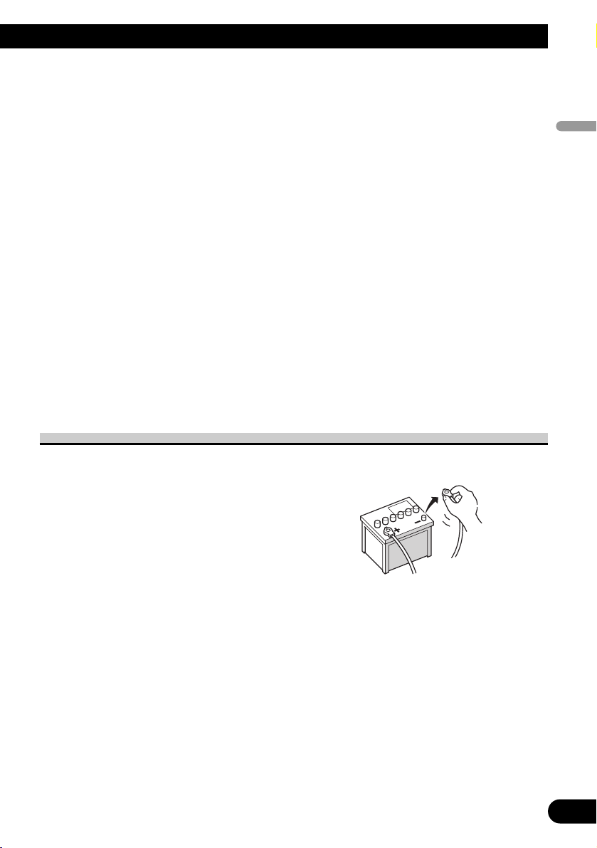
• To avoid shorts in the electrical system, be sure to disconnect the (–)
battery cable before beginning
installation.
Page 6
5
Connecting the System
To prevent damage
• When disconnecting a connector, pull the connector itself. Do not pull the lead, as you
may pull it out of the connector.
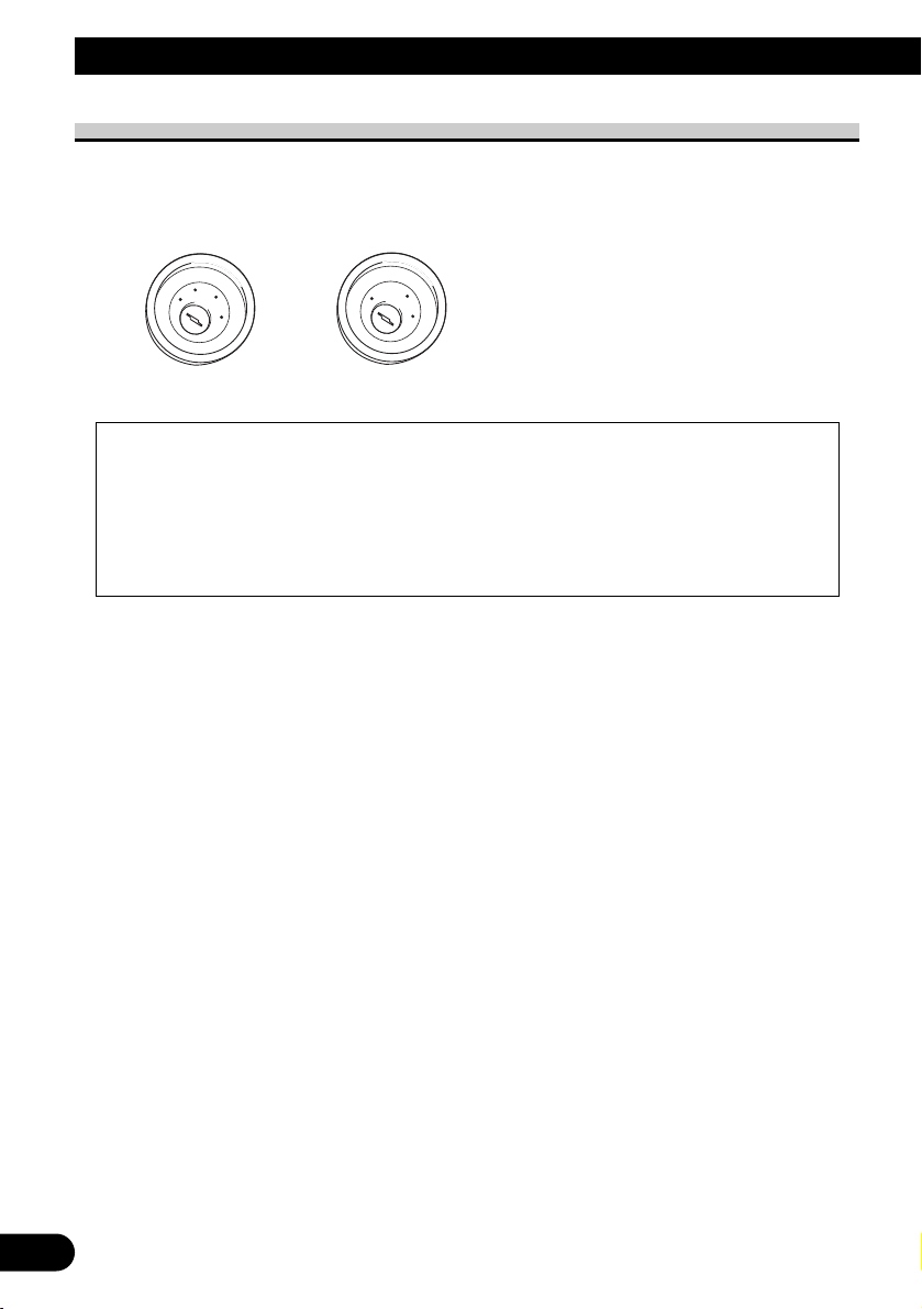
• This navigation system cannot be installed in a vehicle that does not have an ACC
(accessory) position on the ignition switch.
• When replacing the fuse, be sure to only use a fuse of the rating prescribed on the fuse
holder.
• To avoid a short-circuit, cover the disconnected lead with insulating tape. Insulate the
unused speaker leads without fail. There is a possibility of a short-circuit if the leads are
not insulated.
• Attach the connectors of the same colour to the corresponding coloured port, i.e., blue
connector to the blue port, black to black, etc.
• Refer to the owner’s manual for details on connecting the power amp and other units,
then make connections accordingly.
• Since a unique BPTL circuit is employed, do not directly earth the ≠ side of the speaker
lead or connect the ≠ sides of the speaker leads together. Be sure to connect the ≠ side
of the speaker lead to the ≠ side of the speaker lead on this navigation system.
• If the RCA pin jack on this navigation system will not be used, do not remove the caps
attached to the end of the connector.
• Speakers connected to this navigation unit must be high-power with minimum rating of
50 W and impedance of 4 to 8 ohms. Connecting speakers with output and/or impedance
values other than those noted here may result in the speakers catching fire, emitting
smoke, or becoming damaged.
• When the ignition switch is turned on (ACC ON), a control signal is output through the
blue/white lead. Connect to an external power amp’s system remote control terminal
(max. 300 mA 12 V DC). The control signal is output through the blue/white lead, even
if the audio source is switched off.
• When an external power amp is being used with this system, be sure not to connect the
blue lead to the amp’s power terminal. Likewise, do not connect the blue lead to the
power terminal of the auto aerial. Such connection could cause excessive current drain
and malfunction as well as damage to the auto aerial of the vehicle.
• When the “Auto ANT” mode is set to “Radio”, the vehicle’s aerial can be stowed or
turned off by following the instructions below.
– Change the source from radio (AM or FM) to another source
– Turn the source off
– Turn off the ignition switch (ACC OFF)
• If the “Auto ANT” mode is set to “Power”, the vehicle’s aerial can be stowed or turned
off only when the ignition switch is turned off (ACC OFF).
No ACC positionACC position
C
C
A
O
F
N
F
O
S
T
A
R
T
O
F
N
F
O
S
T
A
R
T
Page 7
English
Español
Deutsch
Français
Italiano
Nederlands
6
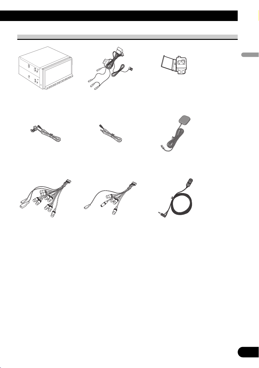
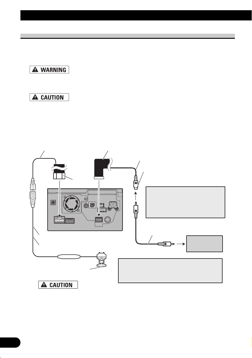
Parts supplied
MicrophoneRCA connector 2
(CONNECTOR 2)
<☞See Page 7, 12, 15, 17
>
RCA connector 1
(CONNECTOR 1)
<☞See Page 10, 13, 16>
GPS aerialExtension lead
(for speed signal)
Extension lead
(for reverse signal)
ConnectorPower cord
<☞See Page 9, 11, 15>
The navigation unit
Page 8
7
Connecting the System
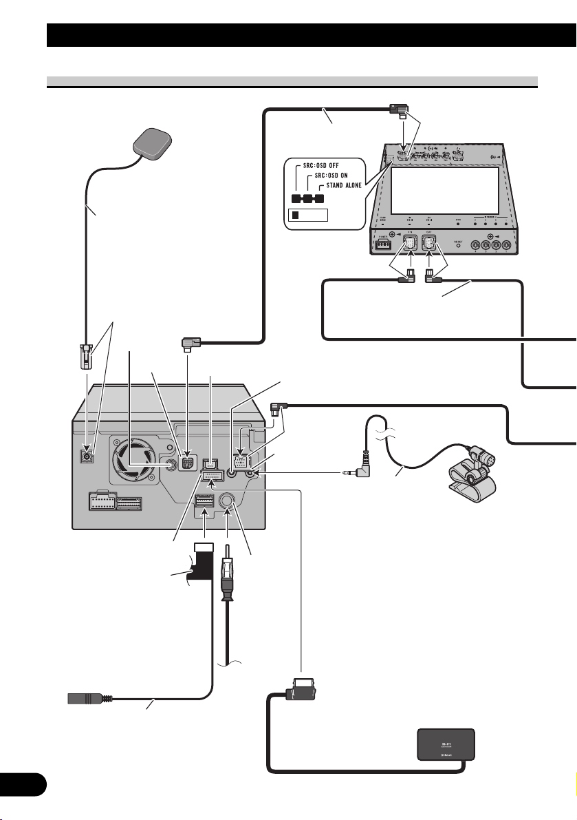
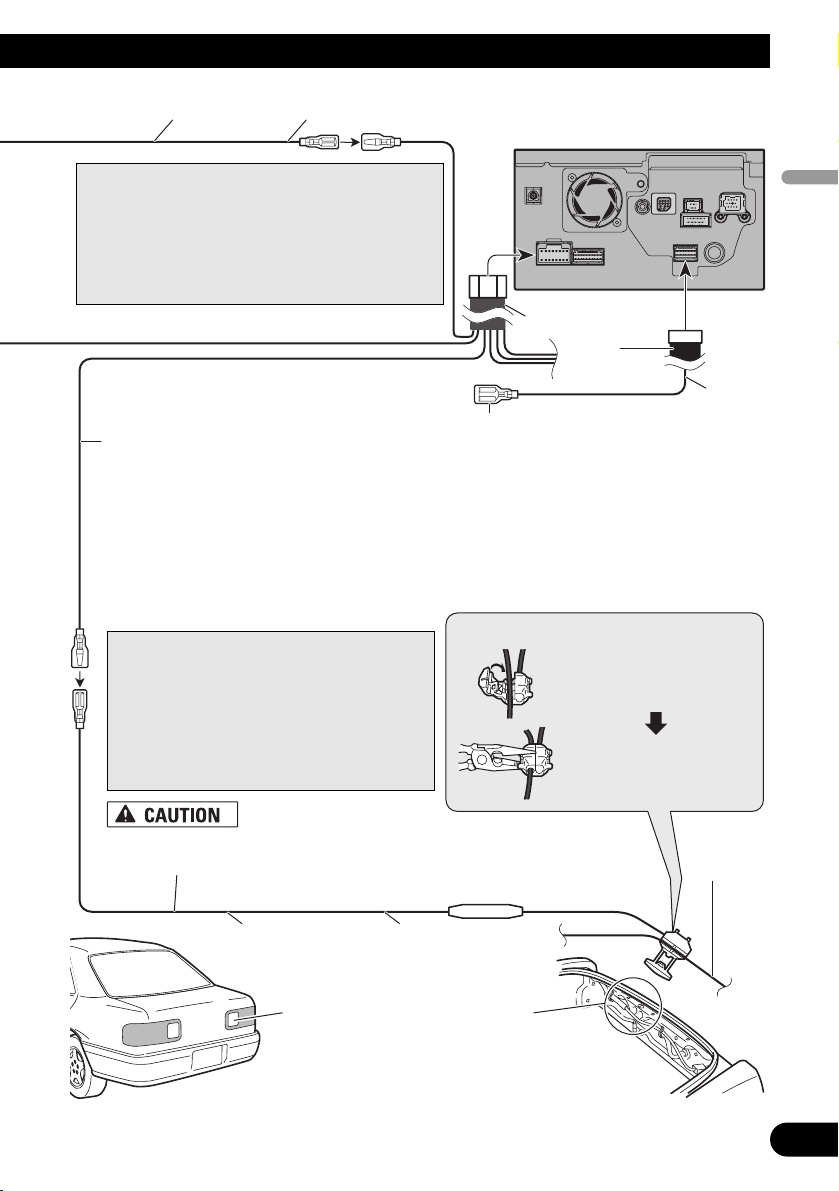
Connecting the system
AV-BUS cable
(supplied with TV tuner)
IP-BUS cable
(supplied with TV tuner)
Black
Black
Bluetooth unit (ND-BT1)
(Sold separately)
Aerial
jack
Vehicle
aerial
The navigation unit
RCA connector 2
20 cm
Red
Hide-away TV tuner
(e.g. GEX-P5700TVP)
(sold separately)
Light grey
5m
GPS aerial
Blue
Blue
Not used.
Microphone input
Microphone
(supplied)
Blue
EXTENSION port
Not used.
Not used.
Jack for Wired Remote
Control Adapters
(WIRED REMOTE INPUT)
Please see the Instruction
Manual for the Wired
Remote Control Adapters
(sold separately).
4 m
Page 9
8
English
Español
Deutsch
Français
Italiano
Nederlands
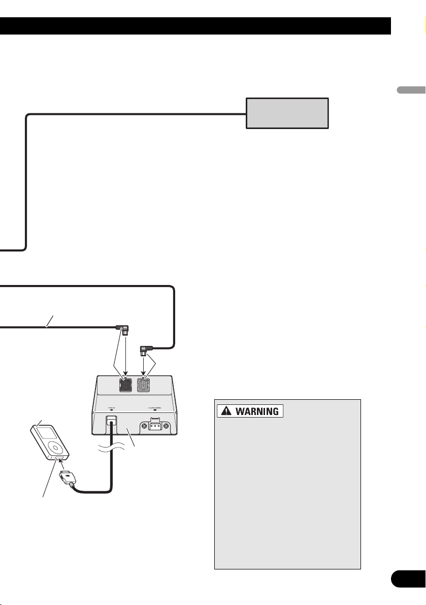
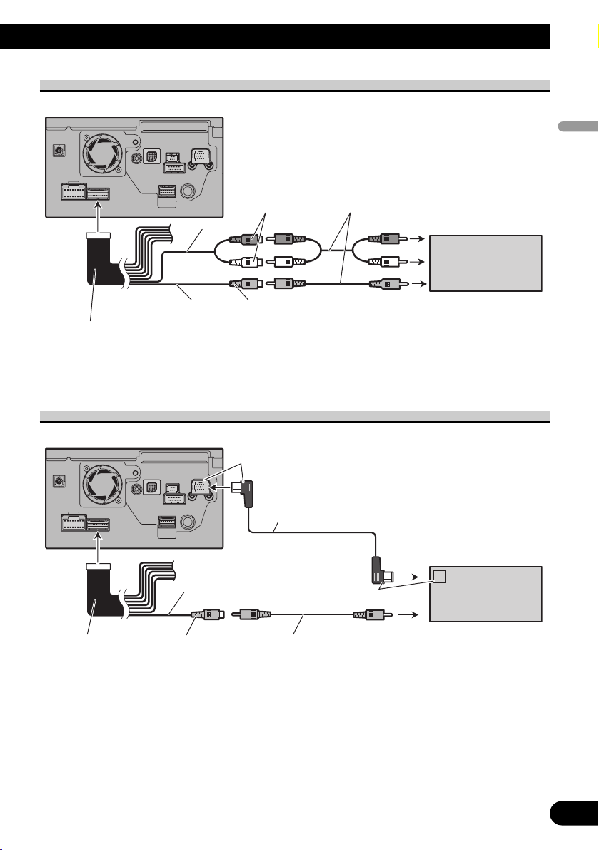
Dock connector port
iPod with
Dock Connector
iPod adapter
(e.g. CD-IB100II)
(sold separately)
Black
IP-BUS cable
(supplied with iPod adapter)
Multi-CD player
(sold separately)
Blue
• To avoid the risk of accident and
the potential violation of applicable
laws, this navigation system should
never be used while the vehicle is
being driven except for navigation
purposes. Also Rear Displays should
not be in a location where it is a visible distraction to the driver.
• In some countries, the viewing of
images on a display inside a vehicle
even by persons other than the driver may be illegal. Where such regulations apply they must be obeyed
and this navigation system’s video
source or TV features should not be
used.
Page 10
9
Connecting the System
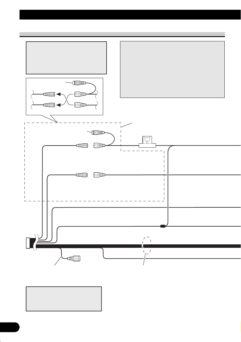
Connecting the power cord (1)
Connect leads of the same
colour to each other.
Cap (*1)
When not using this terminal,
do not remove the cap.
ISO connector
Fuse (10 A)
*1
*2
*4
*3
*5
Yellow (*2)
To terminal always supplied
with power regardless of
ignition switch position.
Red (*4)
To electric terminal controlled
by ignition switch (12 V DC)
ON/OFF.
Yellow (*3)
Back-up
(or accessory)
Red (*5)
Accessory
(or back-up)
Black (earth)
To vehicle (metal) body.
Orange/white
To lighting switch terminal.
Note:
In some vehicles, the ISO connector
may be divided into two. In this case,
be sure to connect to both connectors.
Note:
Depending on the kind of vehicle, the
function of *3 and *5 may be different.
In this case, be sure to connect *2 to *5
and *4 to *3.
Speaker leads
White: Front left +
White/black: Front left ≠
Grey: Front right +
Grey/black: Front right ≠
Green: Rear left + or Subwoofer + (*9)
Green/black: Rear left ≠ or Subwoofer ≠ (*9)
Violet: Rear right + or Subwoofer + (*9)
Violet/black: Rear right ≠ or Subwoofer ≠ (*9)
Yellow/black
If the vehicle can send a mute signal to this terminal,
the mute function can be activated on this navigation
system when the terminal is connected to *8.
Note:
When a subwoofer (*9) is connected to this navigation system instead of a rear speaker, change the
rear output setting in the Initial Setting. (Refer to
the Operation Manual.) The subwoofer output of
this navigation system is monaural.
When using a subwoofer of 70 W (2 Ω), be sure to
connect with violet and violet/black leads of this
navigation unit. Do not connect anything with green
and green/black leads.
Page 11
10
English
Español
Deutsch
Français
Italiano
Nederlands
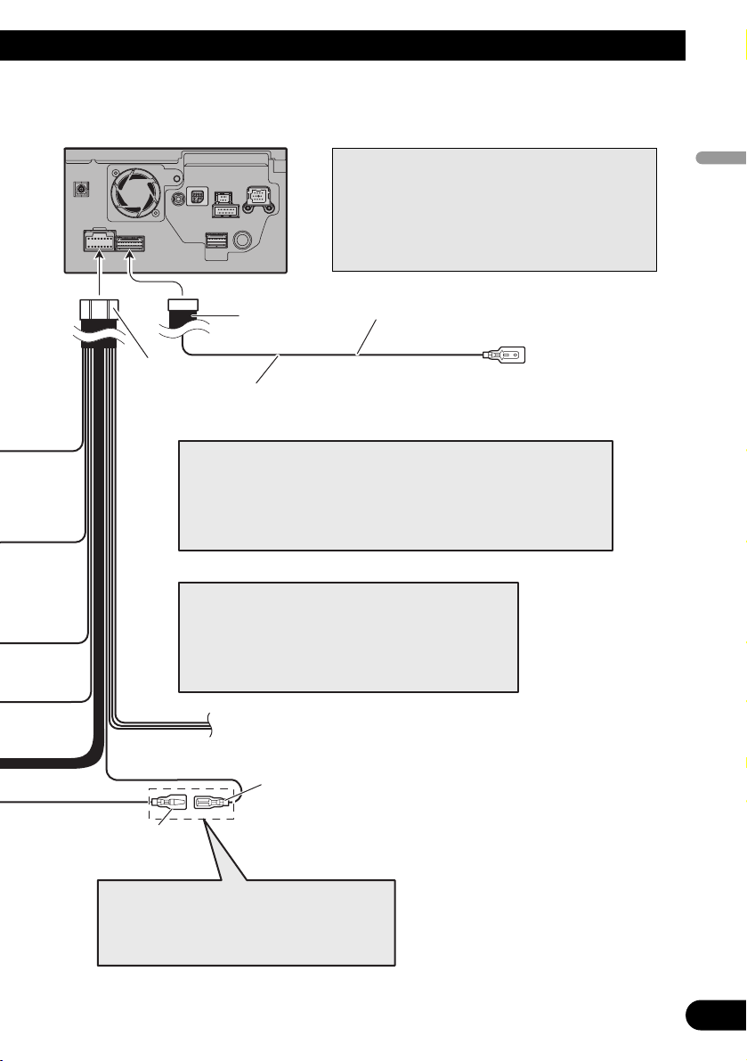
(*8)
Blue (*6)
RCA connector 1 16 cm
The pin position of the ISO connector will differ
depending on the type of vehicle. Connect *6 and
*7 when Pin 5 is an aerial control type. In
other types of vehicle, never connect *6 and *7.
Blue (*7)
To Auto-aerial relay control terminal.
If the vehicle has a glass aerial, connect to
the aerial booster power control terminal
(max. 300 mA 12 V DC).
Yellow/black (MUTE)
If you use equipment with a mute function, connect that equipment to the
Audio Mute lead. If not, keep the Audio Mute lead free of any connections.
Power cord
Note:
Audio source will be set to mute or attenuate, while the following sounds
will not be muted or attenuated. For details, see the Operation Manual.
- voice guidance of the navigation
- incoming ringtone and incoming voice of the mobile phone that is
connected to this navigation system via Bluetooth wireless technology
The navigation unit
Note:
The aerial will automatically retract or turn off, yet the
timing varies depending on the setting. (Refer to page 5.)
For more detailed information on changing the “Auto
ANT” mode, refer to “Switching the auto aerial setting”
in the Operation Manual.
Note:
Cords for this navigation system and those for other
products may be different colours even if they have
the same function. When connecting this navigation
system to another product, refer to the supplied
manuals of both products and connect cords that
have the same function.
Page 12
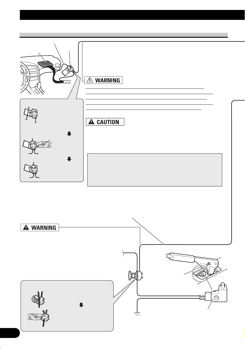
Pink (CAR SPEED SIGNAL INPUT)
The mobile navigation system is connected here to detect the distance
the vehicle travels. Always connect the vehicle’s speed detection
circuit or the ND-PG1 speed pulse generator, sold separately. Failure
to make this connection will increase errors in the location display.
IMPROPER CONNECTION MAY RESULT IN SERIOUS
DAMAGE OR INJURY INCLUDING ELECTRICAL SHOCK,
AND INTERFERENCE WITH THE OPERATION OF THE
VEHICLE’S ANTILOCK BRAKING SYSTEM, AUTOMATIC
GEARBOX AND SPEEDOMETER INDICATION.
LIGHT GREEN LEAD AT POWER
CONNECTOR IS DESIGNED TO DETECT
PARKED STATUS AND MUST BE
CONNECTED TO THE POWER SUPPLY SIDE
OF THE HANDBRAKE SWITCH. IMPROPER
CONNECTION OR USE OF THIS LEAD MAY
VIOLATE APPLICABLE LAW AND MAY
RESULT IN SERIOUS INJURY OR DAMAGE.
Light green
Used to detect the ON/OFF status of the handbrake. This lead must be
connected to the power supply side of the handbrake switch.
If this connection is made incorrectly or omitted, certain
functions of your navigation system will be unusable.
• It is strongly suggested that the speed pulse wire be connected
for accuracy of navigation and better performance of interlock.
• If the speed pulse wire is unavailable for some reason, it is
recommended that the pulse generator (ND-PG1) be used.
Note:
The position of the speed detection circuit and the position of the
parking brake switch vary depending on the vehicle model. For
details, consult your authorised Pioneer dealer or an installation
professional.
11
Connecting the System
Connecting the power cord (2)
Connection method
Clamp the parking brake
switch power supply side lead.
Clamp firmly with
needle-nosed pliers.
Power supply side
Earth side
Handbrake switch
Speed detection circuit lead
Vehicle injection
computer
Connector
Pass the extension cord
and the lead for the
speed detection circuit
through this hole.
Clamp firmly
with needlenosed pliers.
Close the cover.
Connection method
Page 13
RCA
connector 2
Power cord
20 cm
Be sure to use only the supplied extension lead. Use of another lead
could cause fire, smoke and/or damage this navigation system.
12
English
Español
Deutsch
Français
Italiano
Nederlands
Note:
Cords for this navigation system and those for other
products may be different colours even if they have
the same function. When connecting this navigation
system to another product, refer to the supplied
manuals of both products and connect cords that
have the same function.
Violet/white (REVERSEGEAR SIGNAL INPUT)
This is connected so that the navigation system can
detect whether the vehicle is moving forwards or
backwards. Connect the violet/white lead to the
lead whose voltage changes when the reverse gear
is engaged. Unless connected, the sensor may not
detect your vehicle travelling forward/backward
properly, and thus the position of your vehicle
detected by the sensor may be misaligned from the
actual position.
Connection method
Clamp the reversing lamp lead.
Clamp firmly with
needle-nosed pliers.
Reversing
lamp lead
Fuse resistor
Check the position of your vehicle’s
reversing lamp (the one that lights
up when the gearstick is in reverse
[R]) and find the reversing lamp lead
in the boot.
The navigation unit
Extension lead
(for reverse signal)
Extension lead (for speed signal)
5 m
5 m
Note:
When you use the ND-PG1 speed pulse
generator (sold separately), please make sure
to connect this lead.
When you use a rear view camera, please
make sure to connect this lead. Otherwise you
cannot switch to rear view camera picture.
☞
See Page 15.
Yellow/black (GUIDE ON)
When combining this navigation system with
the other Pioneer audio unit for the vehicle, if
the vehicle stereo has yellow/black leads, connect them to those leads. In this way, the vehicle
stereo is automatically muted to reduce the vehicle stereo volume when;
– the guidance audio is output.
– the mobile phone is used via Bluetooth unit.
– you operate the system by voice.
Page 14
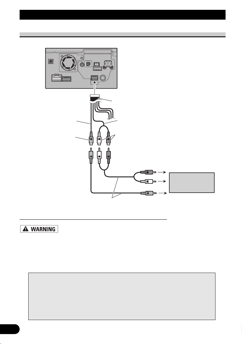
13
Connecting the System
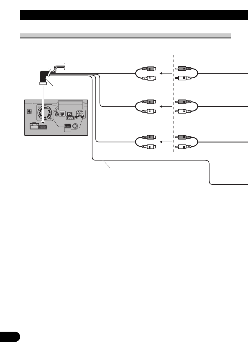
When connecting to separately sold power amp
The navigation unit
Front output
(FRONT OUTPUT)
Subwoofer output
or non-fading output
(SUBWOOFER OUTPUT or
NON-FADING OUTPUT)
Rear output
(REAR OUTPUT)
23 cm
Blue/white
15 cm
To system control terminal of the power amp
(max. 300 mA 12 V DC).
Do not connect this lead to Auto-aerial control
terminal.
15 cm
15 cm
RCA connector 1
Page 15
14
English
Español
Deutsch
Français
Italiano
Nederlands
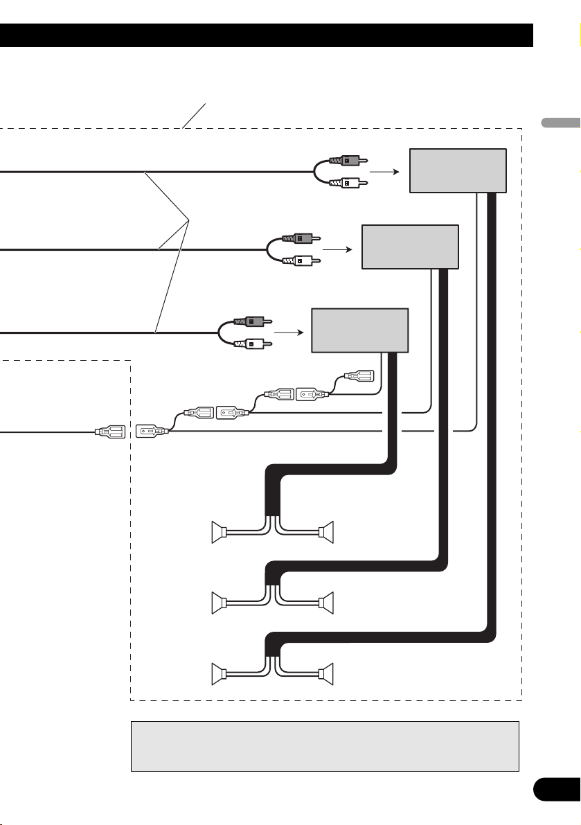
Power amp
(sold separately)
Power amp
(sold separately)
Power amp
(sold separately)
+
≠
+
≠
+
≠
+
≠
+
≠
+
≠
System remote control
RCA cables
(sold separately)
Front speaker
Rear speaker
Subwoofer
Front speaker
Rear speaker
Subwoofer
Left Right
Perform these connections when using
the optional amplifier.
Note:
You can change the RCA output of the subwoofer depending on your subwoofer
system. (Refer to the Operation Manual.)
Page 16
When connecting a rear view camera
When using this navigation system with a rear view camera, automatic switching to video
from a rear view camera is possible when the gearstick is moved to REVERSE (R) position.
Rear view mode also allows you to check what is behind you while driving.
USE INPUT ONLY FOR REVERSE OR MIRROR IMAGE REAR VIEW CAMERA. OTHER USE
MAY RESULT IN INJURY OR DAMAGE.
• The screen image may appear reversed.
• The rear view camera function is to use this navigation system as an aid to keep an eye on trailers,
or backing into a tight parking spot. Do not use this function for entertainment purposes.
• The object in rear view may appear closer or more distant than in reality.
• Please note that the edges of the rear view camera images may differ slightly according to whether
full screen images are displayed when backing, and whether the images are used for checking the
rear when the vehicle is moving forward.
15
Connecting the System
☞
See Page 11.
Violet/white RCA connector 2
20 cm
Brown
Power cord
(REAR VIEW CAMERA IN)
Note:
It is necessary to set to “Camera
Input” in “System Settings” when
connecting the rear view camera. (For
details, see the Operation Manual.)
5 m
Extension lead (for reverse signal)
About connection method
Be sure to use only the supplied extension lead.
Use of another lead could cause fire, smoke
and/or damage this navigation system.
The navigation unit
Fuse resistor
Note:
Connect to the rear view camera. Do not connect
to any other equipment.
RCA cable
(sold separately)
To video output
Rear view
camera
Page 17
When connecting the external video component
• It is necessary to set “AV Input” in “System Settings” to “Video” when connecting the
external video component. (For details, refer to the Operation Manual.)
When connecting the external unit featuring video source
• It is necessary to set “AV Input” in “System Settings” to “EXT” when connecting the
external video component. (For details, refer to the Operation Manual.)
16
English
Español
Deutsch
Français
Italiano
Nederlands
The navigation unit
RCA connector 1
20 cm
20 cm
Red, white
(AUDIO INPUT)
Yellow
(VIDEO INPUT)
RCA
cables
(sold separately)
To audio outputs
External
component
(sold separately)
To video output
The navigation unit
Blue
IP-BUS cable (sold separately)
To IP-BUS output
RCA connector 1
20 cm
Yellow
(VIDEO INPUT)
RCA
cable
(sold separately)
Black
To video output
Pioneer external unit
(sold separately)
video
Page 18
17
Connecting the system
When connecting the rear display
When using a rear display connected to rear video output
NEVER install the rear display in a location that enables the driver to watch the
video source while driving.
This navigation system’s rear video output is for connection of a display to enable passengers in the rear seats to watch the video source. You can switch the rear screen mode in
“AV Source Menu”. (For details, refer to the Operation Manual.)
Notes:
• The map screen navigation images output to the rear display differ from standard NTSC format images. Therefore, their quality will be inferior to the images that appear on the front display.
• The navigation system automatically switches the colour system (NTSC, PAL, SECAM) for
each video and outputs the video on the “Rear Display”. To correctly output each type of
video on the “Rear Display”, we recommend using a “Rear Display” with a function to auto-
matically switch the colour system (e.g. AVD-W1100V).
The navigation unit
RCA connector 2
23 cm
Yellow
(REAR MONITOR OUTPUT)
RCAcables
(sold separately)
15 cm
Red, white
(REAR MONITOR OUTPUT)
To audio inputs
Rear display with
RCA input jacks
To video input
Page 19

Installation
Pioneer does not recommend that you install or service your navigation system
yourself. Installing or servicing the navigation system may expose you to risk
of electric shock or other hazards. Refer all installation and servicing of your
navigation system to authorised Pioneer service personnel.
• Never install this navigation system in places where, or in a manner that:
* It could injure the driver or passengers if the vehicle stops suddenly.
* It may interfere with the driver’s operation of the vehicle, such as on the
floor in front of the driver’s seat, or close to the steering wheel or gearstick.
• Make sure there is nothing behind the dashboard or panelling when drilling
holes in them. Be careful not to damage fuel lines, brake lines, electronic
components, communication wires or power cables.
• When using screws, do not allow them to come into contact with any electrical lead. Vibration may damage wires or insulation, leading to a short circuit
or other damage to the vehicle.
• To ensure proper installation, use the supplied parts in the manner specified.
If any parts other than the supplied ones are used, they may damage internal
parts of this navigation system or they may work loose and the navigation
system may become detached.
• It is extremely dangerous to allow the GPS aerial lead or microphone lead to
become wound around the steering column or gearstick. Be sure to install
this navigation system in such a way that it will not obstruct driving.
• Make sure that leads cannot get caught in a door or the sliding mechanism of
a seat, resulting in a short circuit.
• Please confirm the proper function of your vehicle’s other equipment following installation of the navigation system.
• Certain government laws may prohibit or restrict the placement and use of
this system in your vehicle. Please comply with all applicable laws and regulations regarding the use, installation and operation of your navigation system.
• Do not install this navigation system where it may (i) obstruct the driver’s
vision, (ii) impair the performance of any of the vehicle’s operating systems
or safety features, including airbags, hazard lamp buttons or (iii) impair the
driver’s ability to safely operate the vehicle.
18
English
Español
Deutsch
Français
Italiano
Nederlands
Page 20

19
Installation
• Install this navigation system between the driver’s seat and front passenger
seat so that it will not be hit by the driver or passenger if the vehicle stops
quickly.
• Never install this navigation system in front of or next to the place in the
dash, door, or pillar from which one of your vehicle’s airbags would deploy.
Please refer to your vehicle’s Owner’s Manual for reference to the deployment area of the frontal airbags.
• Do not install this navigation system in a place where it will impair the performance of any of the vehicle’s operating systems, including airbags and
headrests.
To guard against electromagnetic interference
• In order to prevent interference, set the following items as far as possible from this navi-
gation system, other cables or leads:
- TV aerial and aerial lead
- FM, MW/LW aerial and its lead
- GPS aerial and its lead
In addition you should lay or route each aerial lead as far as possible from other aerial
leads.
Do not bind them together, lay or route them together, or cross them.
Such electromagnetic noise will increase the potential for errors in the location display.
Before installing
• Consult with your nearest dealer if installation requires the drilling of holes or other mod-
ifications of the vehicle.
• Before making a final installation of this navigation system, temporarily connect the
wiring to confirm that the connections are correct and the system works properly.
• Do not install this navigation system in a position where the opening of the LCD panel is
obstructed by any obstacles, such as the shift lever. Before installing this navigation system, be sure to leave sufficient space so that the LCD panel does not obstruct the shift
lever when it is fully opened. This may cause interference with the shift lever, or a malfunction of the mechanism of this navigation system.
Page 21
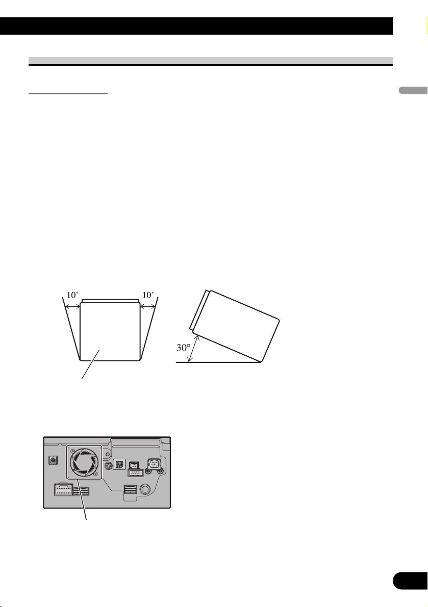
Installing this navigation system
Installation notes
• Do not install this navigation system in places where it may become subject to high temperatures or humidity, such as:
* Places close to a heater, vent or air conditioner.
* Places exposed to direct sunlight, such as on top of the dashboard.
* Places that may be splashed by rain, for example close to the door.
• Install this navigation system in an area strong enough to bear its weight. Choose a position where this navigation system can be firmly installed, and install it securely.
If this navigation system is not securely installed, the current location of the vehicle cannot be displayed correctly.
• Install the navigation system horizontally on a surface within 0 degrees to 30 degrees
tolerance. If the installation angles on the left and right sides exceed 5 degrees, the
allowable range can be increased to 10 degrees by making corrective adjustments.
(Refer to “Correcting the installation angle” in the Operation Manual.) If connection of
the pink lead (CAR SPEED SIGNAL INPUT) is omitted, the angles on the left and right
sides are allowable to within five degrees. Improper installation of the unit with the surface tilted more than these tolerances increases the potential for errors in the location
display, and might otherwise cause reduced display performance.
• The cords must not cover up the area shown in the figure below. This is necessary to
allow the amplifiers and navigation mechanism to dissipate heat.
• The semiconductor laser will be damaged if it overheats, so don’t install the navigation
unit anywhere hot — for instance, near a heater outlet.
If the angle exceeds five degrees,
please make corrective adjustments.
20
English
Español
Deutsch
Français
Italiano
Nederlands
Do not cover this area.
Page 22
21
Installation
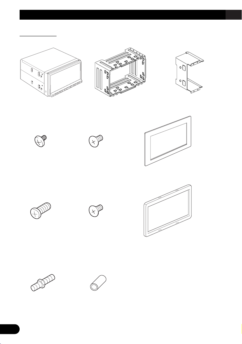
Parts supplied
Parts marked (*) are pre-installed.
Rubber bushDouble-ended screw
Trim ringScrew for fixing
the side bracket*
(5 × 6 mm) (4 pcs.)
Screw*
(3 × 6 mm)
(8 pcs.)
Frame
Flush surface screw
(5 × 6 mm) (4 pcs.)
Binding screw
(5 × 6 mm) (8 pcs.)
Side bracket*
(2 pcs.)
Holder*The navigation unit
Page 23
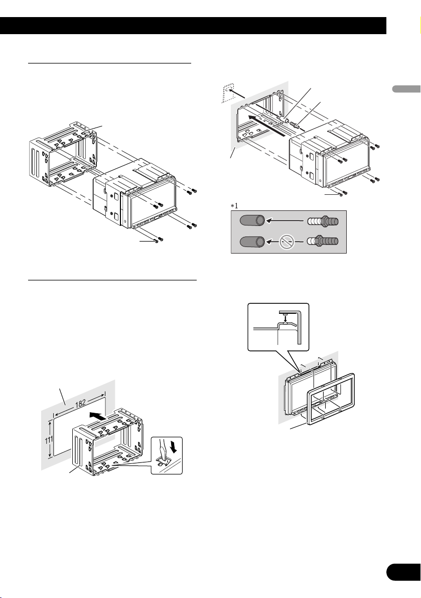
Before installing this navigation unit
• Remove the holder.
Loosen the screws (3 × 6 mm) to
remove the holder.
Installation with the holder and side bracket
1.
Install the holder into the dashboard.
After inserting the holder into the dashboard, select and bend the tabs appropriate to the thickness of the dashboard
material. (Install this navigation unit as
firmly as possible using the top and
bottom tabs. To secure this navigation
unit, bend the tabs 90 degrees.)
2. Install this navigation unit and
fasten the screws.
Be sure to attach the rubber bush to the
long end of double-ended screw.
3. Attach the trim ring.
Trim ring
Dashboard
Screw (3 × 6 mm)
Rubber bush*
1
Double-ended
screw
Dashboard
Holder
Holder
Screw (3 × 6 mm)
22
English
Español
Deutsch
Français
Italiano
Nederlands
Page 24
23
Installation
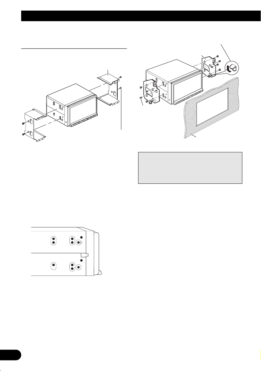
Installation using the screw holes on
the side of the navigation unit
1. Remove the side brackets.
2. Fastening the navigation unit to
the factory radio-mounting
bracket.
Position the navigation unit so that its
screw holes are aligned with the screw
holes of the bracket, and tighten the
screws at 3 or 4 locations on each side.
Use either the binding screws (5 × 6 mm)
or flush surface screws (5 × 6 mm),
depending on the shape of the bracket’s
screw holes.
Note:
In some types of automobiles, discrepancy
may occur between the navigation unit and
the dashboard. If this happens, use the supplied frame to fill the gap.
Side bracket
Screw for fixing the side bracket
(5 × 6 mm)
If the pawl gets in the
way, bend it down
Factory radio mounting bracket
Binding screw or
flush surface screw
Be sure to use the
screws supplied
with this navigation
system.
Dashboard or console
Page 25
Installing the GPS aerial
• Do not cut the GPS aerial lead to shorten it or use an extension to make it
longer. Altering the aerial cable could result in a short circuit or malfunction
and permanent damage to the navigation system.
Installation notes
• When installing the GPS aerial inside the vehicle, be sure to use the metal sheet provid-
ed with your system. If this is not used, the reception sensitivity will be poor.
• Do not cut the accessory metal sheet. This would reduce the sensitivity of the GPS aeri-
al.
• Take care not to pull the aerial lead when removing the GPS aerial. The magnet attached
to the aerial is very powerful, and the lead may become detached.
• The GPS aerial is installed with a magnet. When installing the GPS aerial, be careful
not to scratch the vehicle body.
• When installing the GPS aerial on the outside of the vehicle, always put it in the vehicle
when going through an automatic vehicle wash. If it is left on the outside it may be
knocked off and scratch the vehicle body.
• Do not paint the GPS aerial, as this may affect its performance.
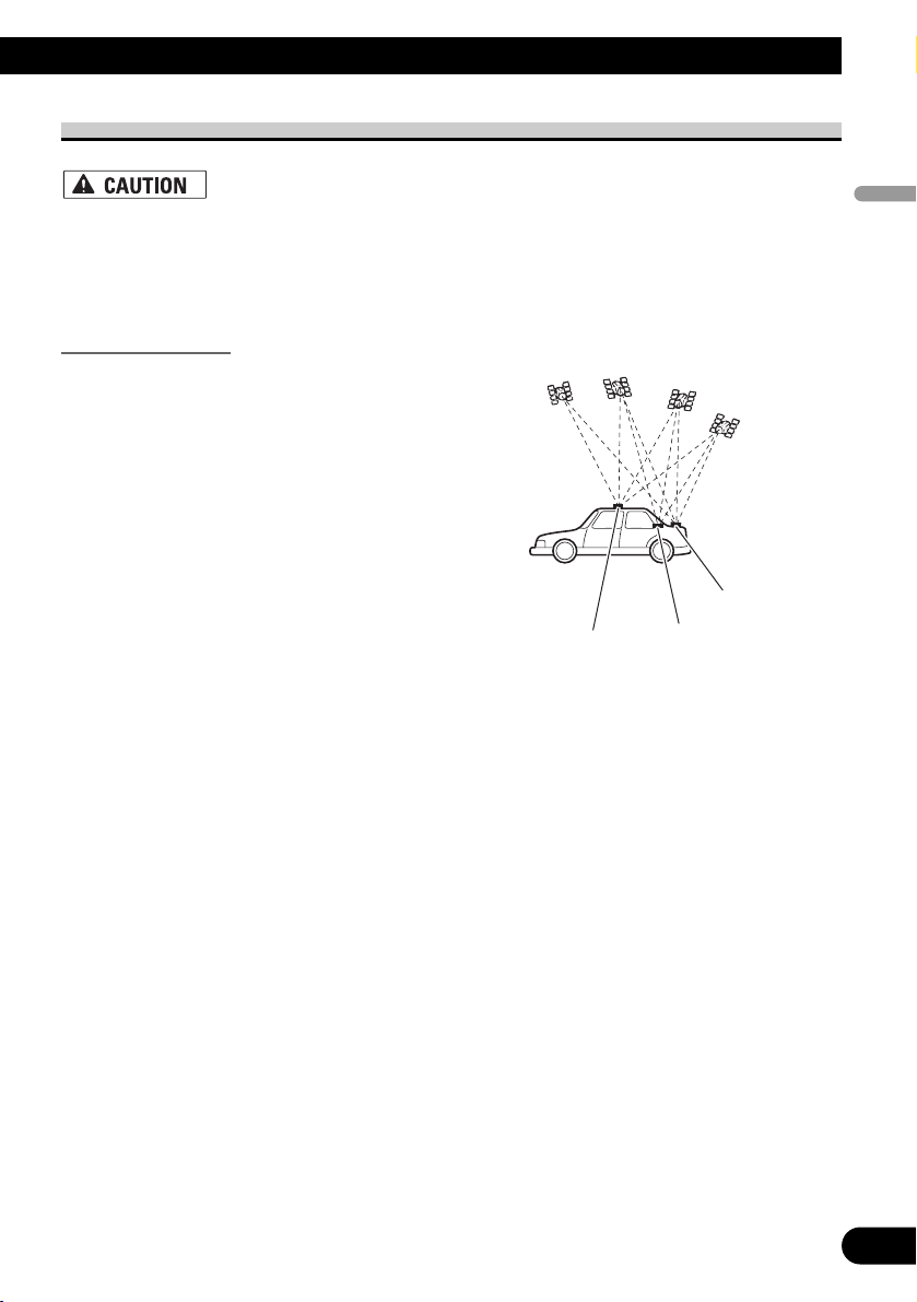
• The aerial should be installed on a
level surface where radio waves will
be blocked as little as possible. Radio
waves cannot be received by the aerial
if reception from the satellite is
blocked.
Installation on the vehicle roof or boot
lid is recommended to optimise reception.
24
English
Español
Deutsch
Français
Italiano
Nederlands
Boot lid
Roof
Rear shelf
Page 26
25
Installation
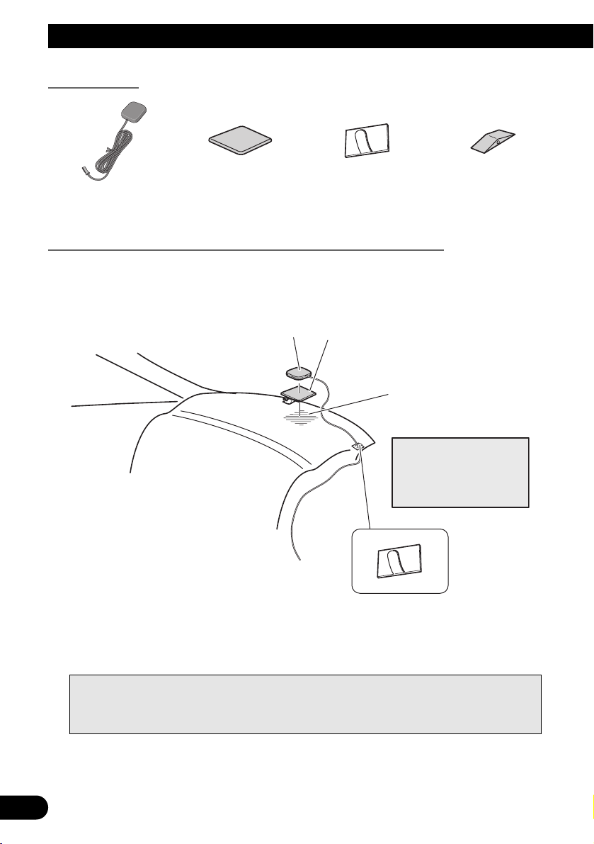
Parts supplied
When installing the aerial inside the vehicle (on the rear shelf)
Affix the metal sheet on as level a surface as possible where the GPS aerial faces the window. Place the GPS aerial on the metal sheet. (The GPS aerial is fastened with its magnet.)
Notes:
• When attaching the metal sheet, do not cut it into small pieces.
• Some models use window glass that does not allow signals from GPS satellites to pass through.
On such models, install the GPS aerial on the outside of the vehicle.
Waterproof padClamp (5 pcs.)Metal sheetGPS aerial
GPS aerial
Metal Sheet
Peel off the protective sheet
on the rear.
Make sure the surface is
free of moisture, dust,
grime, oil, etc., before
affixing the metal sheet.
Note:
The metal sheet
contains a strong adhesive
which may leave a mark on
the surface if it is removed.
Clamps
Use clamps to secure the
lead where necessary inside
the vehicle.
Page 27
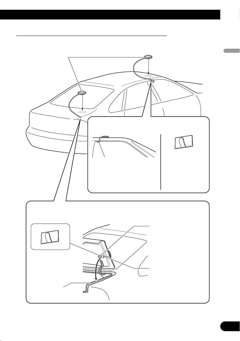
When installing the aerial outside the vehicle (on the body)
Put the GPS aerial in a position as level as possible, such as on the roof or boot lid. (The
GPS aerial is fastened with a magnet.)
26
English
Español
Deutsch
Français
Italiano
Nederlands
GPS aerial
When routing the lead in from the top of the
door
Make a U-shaped loop in the lead
on the outside to prevent rainwater
from flowing along the lead into the
interior of the vehicle.
When routing the lead in from inside the boot
Clamps
Use clamps to secure the
lead where necessary inside
the vehicle.
Rubber packing
Clamps
Use clamps to secure
the lead where
necessary inside the
vehicle.
Waterproof pad
Make sure the waterproof pad
contacts the top of the rubber
packing.
Make a U-shaped loop in the
lead outside the rubber
packing to prevent rainwater
from flowing along the lead
into the interior of the vehicle.
Page 28
27
Installation
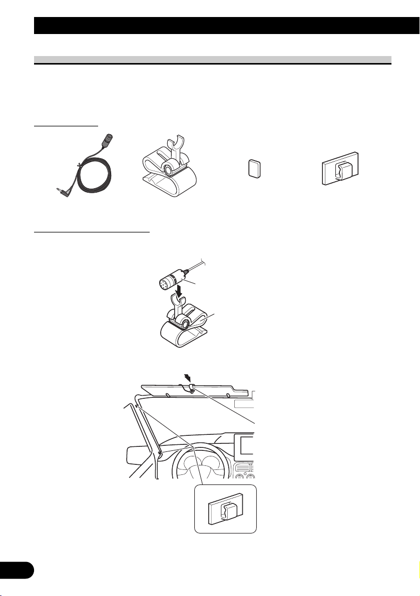
Installing the microphone
• Install the microphone in a place where its direction and distance from the driver make it
easiest to pick up the driver’s voice.
• Make sure to connect the microphone to the navigation system after the system is turned
off. (ACC OFF)
Parts supplied
Mounting on the sun visor
1. Install the microphone in the microphone clip.
2. Attach the microphone clip to sun visor.
Install the microphone on the sun visor when it is in the up position. It cannot recognise
the driver’s voice if the sun visor is in the down position.
Clamp (5 pcs.)Double-sided tapeMicrophone clipMicrophone
Microphone
Microphone clip
Microphone clip
Clamps
Use clamps to secure the
lead where necessary
inside the vehicle.
Page 29
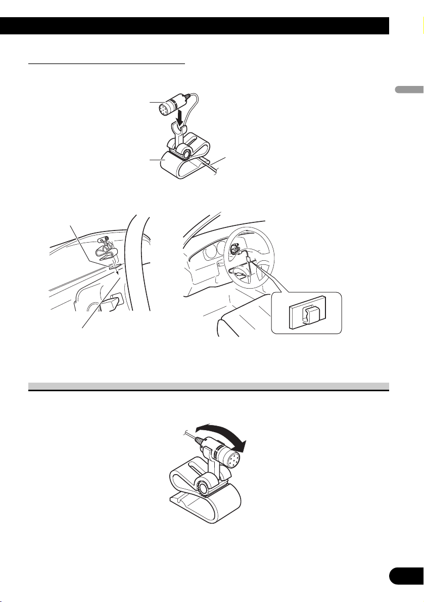
Installation on the steering column
1. Install the microphone in the microphone clip.
2. Mount the microphone clip on the steering column.
Adjusting the microphone angle
The microphone angle can be adjusted by moving forward or backward the microphone
clip angle.
28
English
Español
Deutsch
Français
Italiano
Nederlands
Microphone
Microphone clip
Fit the microphone cord in the groove.
Double-sided tape
Clamps
Use clamps to secure the
lead where necessary
inside the vehicle.
Install the microphone clip on the
steering column, keeping it away
from the steering wheel.
Page 30
29
After Installing this Navigation System
1. Reconnecting the battery.
First, double-check that all connections are correct and that this navigation system is
installed correctly. Reassemble all vehicle components that you previously removed. Then
reconnect the negative (–) cable to the negative (–) terminal of the battery.
2. Start the engine.
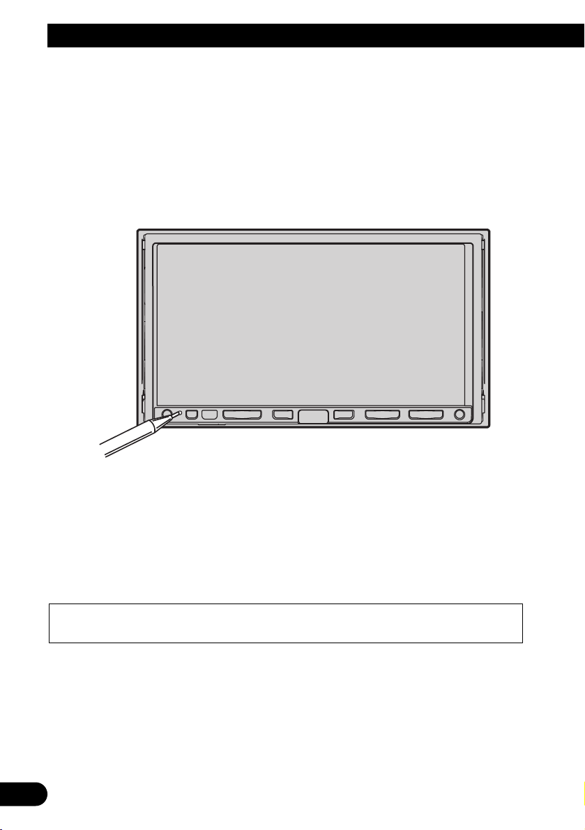
3. Press the RESET button on the navigation unit.
Press the RESET button on the navigation system using a pointed object such as the tip of
a pen.
4. Enter the following settings:
1. Make any necessary installation angle adjustments. (Refer to “Correcting the installation
angle” in “Chapter 9” of the Operation Manual.)
2. Change “Regional Settings” if necessary. (Refer to “Customising the Regional Settings”
in “Chapter 9” of the Operation Manual.)
3. Drive until the initialised sensors start operating normally.
Set the navigation system as explained in the Operation Manual or Hardware Manual.
After installing this navigation system, be sure to check at a safe place that the vehicle is performing normally.
Page 31

30
English
Español
Deutsch
Français
Italiano
Nederlands
Page 32

1
Información importante de seguridad
ACERCA DE ESTE MANUAL
Este manual explica cómo instalar este sistema de navegación en su automóvil. El funcionamiento de este sistema de navegación se explica en el Manual de instrucciones o Manual de hardware independiente del sistema
de navegación. Léalos antes de utilizar este sistema de navegación.
LEA TODAS ESTAS INSTRUCCIONES RELACIONADAS CON SU SISTEMA DE
NAVEGACIÓN Y GUÁRDELAS PARA EMPLEARLAS COMO REFERENCIA EN EL FUTURO
No intente instalar o revisar usted mismo el sistema de navegación. La instalación o
revisión del sistema de navegación por personas sin formación o experiencia en
equipos electrónicos y accesorios para automóviles puede ser peligrosa y podría
exponerle a una descarga eléctrica o a otros peligros.
1. Lea completa y detenidamente este manual antes de instalar su sistema de navegación.
2. Guarde al alcance de la mano este manual para utilizarlo como referencia en el futuro.
3. Ponga mucha atención a todas las advertencias de este manual y siga cuidadosamente las instrucciones.
4. En ciertas circunstancias, este sistema de navegación puede mostrar una información errónea de la
posición de su vehículo, la distancia de los objetos mostrados en la pantalla y las direcciones de la
brújula. Además, el sistema tiene ciertas limitaciones, incluyendo la incapacidad de identificar calles
de una dirección, restricciones temporales de tráfico y zonas donde la conducción pueda resultar peligrosa. Haga uso de su buen juicio en función de las condiciones de conducción reales.
5. Al igual que con cualquier otro accesorio del interior, el sistema de navegación nunca deberá distraerle ni poner en peligro el manejo seguro de su vehículo. Si tiene dificultad para utilizar el sistema o leer
la pantalla, haga los ajustes necesarios con el vehículo estacionado en un lugar seguro.
6. Recuerde ponerse siempre el cinturón de seguridad cuando maneje su automóvil. En el caso de sufrir
un accidente, sus lesiones pueden ser mucho más graves si no tiene bien puesto su cinturón de seguridad.
7. En algunos países, las leyes pueden limitar la ubicación y el uso de sistemas de navegación en el
vehículo. Cumpla con todas las leyes y normas pertinentes en cuanto a la instalación y el funcionamiento de su sistema de navegación.
Page 33

English
Español
Deutsch
Français
Italiano
Nederlands
Información importante de seguridad .. 1
ACERCA DE ESTE MANUAL ...................... 1
LEA TODAS ESTAS INSTRUCCIONES
RELACIONADAS CON SU SISTEMA
DE NAVEGACIÓN Y GUÁRDELAS
PARA EMPLEARLAS COMO
REFERENCIA EN EL FUTURO .............. 1
Conexión del sistema ................................ 3
Antes de instalar este sistema de navegación .... 4
Para impedir daños ............................................ 5
Partes suministradas .......................................... 6
Conexión del sistema ........................................ 7
Conexión del cable de alimentación (1) ............ 9
Conexión del cable de alimentación (2) .......... 11
Conexión al amplificador de potencia que se
vende por separado .................................. 13
Conexión de una cámara para visión trasera .. 15
Al conectar el componente de vídeo externo .. 16
Al conectar la unidad externa con fuente de
vídeo ..........................................................16
Al conectar la pantalla posterior ......................17
-
Al usar una pantalla posterior conectada a la
salida de vídeo trasera
Instalación ................................................ 18
Para impedir que se produzcan interferencias
electromagnéticas .................................... 19
Antes de la instalación .................................... 19
Instalación de este sistema de navegación ...... 20
-
Notas acerca de la instalación
-
Partes suministradas
-
Antes de instalar esta unidad de navegación
-
Instalación con el soporte y el soporte lateral
-
Instalación usando los orificios roscados
en el lado de la unidad de navegación
Instalación de la antena GPS .......................... 24
-
Notas acerca de la instalación
-
Partes suministradas
-
Cuando instale la antena en el interior del
vehículo (en el estante trasero)
-
Cuando instale la antena en el exterior del
vehículo (en la carrocería)
Instalación del micrófono ................................27
-
Partes suministradas
-
Montaje en el parasol
-
Instalación en la columna de dirección
Ajuste del ángulo del micrófono ......................28
Después de instalar este sistema de
navegación ........................................ 29
2
Índice
Page 34

Conexión del sistema
3
Pioneer aconseja que no realice usted mismo la instalación del sistema de navegación.
Recomendamos que sólo instale y configure este sistema de navegación el personal de
servicio autorizado de Pioneer, que cuenta con formación especializada y experiencia
en el campo de la electrónica móvil.
NUNCA EFECTÚE EL MANTENIMIENTO DE ESTE SISTEMA DE NAVEGACIÓN USTED MISMO. La instalación o el mantenimiento del sistema de navegación y de los cables de conexión asociados puede exponerle al riesgo de una descarga eléctrica u otros peligros, y puede ocasionar daños en el sistema de navegación que
no cubre la garantía.
• Si decide efectuar la instalación usted mismo y cuenta con formación especializada y experiencia en la instalación de sistemas electrónicos móviles, siga
con cuidado todos los pasos descritos en el Manual de instalación.
• Asegure todo el cableado con abrazaderas de cables o cinta para usos eléctricos. No permita que el cableado pelado permanezca descubierto.
• No enchufe el cable amarillo de este sistema de navegación directamente a la
batería del vehículo. Si lo hace, puede que la vibración del motor acabe
provocando un problema relacionado con el aislamiento en el punto por
donde el cable cruza del compartimiento del pasajero al compartimiento del
motor. Si se rompe el aislamiento del cable amarillo como resultado del contacto con partes metálicas, puede producirse un cortocircuito y generar por
tanto un peligro considerable.
• Es peligrosísimo dejar que el cable de la antena GPS y el cable del micrófono
se enrollen en la base del volante o en la palanca de cambios. Asegúrese de
instalar este sistema de navegación, los cables de la unidad y el cableado de
tal forma que no dificulten o impidan la conducción.
• Asegúrese de que todos los cables estén enrutados y sujetos de manera que
no entorpezcan o queden atrapados con alguna de las partes móviles del
vehículo, en especial con el volante, la palanca de cambio, el freno de mano,
las guías de los asientos deslizantes, las puertas o con alguno de los controles
del vehículo.
Page 35

English
Español
Deutsch
Français
Italiano
Nederlands
4
• No enrute cables adonde vayan a estar sometidos a altas temperaturas. Si se
calienta el aislamiento, los cables pueden resultar dañados y, como consecuencia, puede producirse un cortocircuito o una avería y el sistema de navegación puede sufrir daños permanentes.
• No corte el cable de la antena GPS para reducir su longitud ni utilice una
extensión para alargarlo. La alteración del cable de la antena puede causar
un cortocircuito.
• No acorte ningún cable. En el caso de que lo haga, el circuito de protección
(el portafusibles, la resistencia de fusible o el filtro, etc.) puede que no funcione correctamente.
• Nunca suministre alimentación a otros productos electrónicos cortando el
aislamiento del cable de alimentación del sistema de navegación y tomando
corriente de él. La capacidad nominal del cable se excederá y causará un
recalentamiento.
• El cable negro es de conexión a tierra. Conecte este cable a una toma de tierra
distinta de productos de alta tensión como, por ejemplo, amplificadores de
potencia. No conecte a tierra más de un componente junto con la conexión a
tierra de otro componente. Por ejemplo, debe conectar a tierra por separado
cualquier unidad de amplificador y este sistema de navegación. La conexión
conjunta de la tierra de uno y otro puede ocasionar un incendio y/o dañar los
productos si se desprende la tierra de cada uno.
Antes de instalar este sistema de navegación
• Este sistema de navegación es para vehículos con batería de 12 voltios y con conexión a
tierra negativa. Compruebe el voltaje de la batería de su vehículo antes de proceder a la
instalación.
• Para evitar cortocircuitos en el sistema
eléctrico, asegúrese de desconectar el
cable de la batería (–) antes de comenzar con la instalación.
Page 36

5
Conexión del sistema
Para impedir daños
• Cuando desconecte un conector, tire del propio conector. No tire del cable porque podría
sacarlo del conector.
• Este sistema de navegación no puede instalarse en un vehículo que no disponga de la
posición ACC (accesorio) en el interruptor de encendido.
• Al sustituir el fusible, utilice sólo un fusible de la clasificación prescrita en el soporte el
fusible.
• Para evitar cortacircuitos, cubra el conductor desconectado con cinta aislante. Aísle los
cables de altavoz sin fallo que no se usen. Existe la posibilidad de cortacircuito si estos
no se aíslan.
• Acople los conectores de un color determinado al puerto correspondiente del mismo
color, es decir, el conector azul al puerto azul, el conector negro al puerto negro, etc.
• Consulte el manual del propietario para obtener información sobre la conexión del
amplificador de potencia y de otras unidades y, a continuación, realice las conexiones de
manera acorde.
• Como se utiliza un circuito BPTL único, no conecte directamente a tierra el extremo ≠
del cable del altavoz, ni conecte juntos los extremos ≠ de los cables de los altavoces.
Asegúrese de conectar el extremo ≠ del cable del altavoz al extremo ≠ del cable del
altavoz de este sistema de navegación.
• Si no se va a utilizar el enchufe de clavijas RCA de este sistema de navegación, no retire
las tapas sujetas al extremo del conector.
• Los altavoces conectados a esta unidad de navegación deben ser de gran potencia con 50
W como mínimo y una impedancia de 4 a 8 ohmios. Si se conectan los altavoces con
valores de potencia o impedancia diferentes a los indicados aquí los altavoces podrían
incendiarse, emitir humo o dañándose.
• Al conectar el interruptor de encendido (ACC ON), se envía una señal de control por el
cable azul/blanco. Conéctelo al terminal de control remoto del sistema externo de amplificadores de potencia (máx. 300 mA 12 V CC). La señal de control se envía por el cable
azul/blanco, aunque la fuente de audio esté desconectada.
• Cuando se emplea un amplificador de potencia externo con este sistema, asegúrese de
no conectar el cable azul al terminal de alimentación del amplificador. De la misma
manera, no conecte el cable azul al terminal de alimentación de la antena automática.
Una conexión de este tipo podría provocar una pérdida de corriente excesiva y un mal
funcionamiento, así como daños en la antena automática del vehículo.
• Si el modo “Auto ANT” está en “Radio”, se puede estibar o apagar la antena del
vehículo siguiendo alguno de estos pasos.
– Cambiar la fuente de radio (AM o FM) a otra fuente.
– Desactivar la fuente.
– Desactivar el interruptor de encendido (ACC OFF).
• Si se fija el modo “Auto ANT” como “Power”, sólo se puede estibar o apagar la antena
del vehículo mientras el interruptor de encendido esté apagado (ACC OFF).
Sin posición ACCPosición ACC
C
C
A
O
F
N
F
O
S
T
A
R
T
O
F
N
F
O
S
T
A
R
T
Page 37

English
Español
Deutsch
Français
Italiano
Nederlands
6
Partes suministradas
MicrófonoConector RCA 2
(CONNECTOR 2)
<☞Consulte las páginas 7,
12, 15 y 17
>
Conector RCA 1
(CONNECTOR 1)
<☞Consulte las páginas
10, 13 y 16>
Antena GPSCable de extensión
(para señal de aceleración)
Cable de extensión
(para la señal de marcha atrás)
ConectorCable de alimentación
<☞Consulte las páginas
9, 11 y 15>
La unidad de navegación
Page 38

7
Conexión del sistema
Conexión del sistema
Negro
Negro
Unidad de Bluetooth (ND-BT1)
(Se vende por separado)
Conector
de antena
Antena
del vehículo
La unidad
de navegación
Conector RCA 2
20 cm
Rojo
5m
Azul
Azul
No se usa.
Entrada
de micrófono
Micrófono
(suministrado)
Azul
Puerto de EXTENSION
No se usa.
No se usa.
Clavija para adaptadores de
control remoto alámbricos
(WIRED REMOTE
INPUT). Consulte el
Manual de instrucciones de
los adaptadores de control
remoto por cable (vendidos
por separado).
4 m
Antena GPS
Gris claro
Cable AV-BUS
(suministrado con el
sintonizador de TV)
Sintonizador TV ocultalejos
(p. ej. GEX-P5700TVP)
(se vende por separado)
Cable IP-BUS
(suministrado con el sintonizador TV)
Page 39

8
English
Español
Deutsch
Français
Italiano
Nederlands
Puerto de conector de acoplamiento
iPod con conector
de acoplamiento
Adaptador iPod
(p. ej., CD-IB100II)
(vendido por separado)
Negro
Azul
Reproductor
de Multi-CD
(vendido por separado)
Cable IP-BUS
(suministrado con el adaptador iPod)
• Para evitar el riesgo de accidente y la
posible infracción de las leyes correspondientes, este sistema de navegación
no debe utilizarse nunca durante la
conducción del vehículo con otra finalidad distinta a la navegación. También
debe tenerse en cuenta que las pantallas traseras no deben situarse en un
sitio que suponga una distracción clara
para el conductor.
• En algunos países, la visualización de
imágenes en una pantalla en el interior
de un vehículo incluso por parte de los
pasajeros puede ser ilegal. Es preciso
respetar dichas normas donde estén en
vigor y no deben utilizarse las funciones de fuente de vídeo o TV de este
sistema de navegación.
Page 40

9
Conexión del sistema
Conexión del cable de alimentación (1)
Conector ISO
*1
*2
*4
*3
*5
Naranja/blanco
Nota:
Amarillo/negro
Nota:
Según cual sea el tipo de vehículo, la
función de *3 y *5 puede variar. En tal
caso, asegúrese de conectar *2 a *5 y
*4 a *3.
Tapa (*1)
Cuando este terminal no esté
en uso, no extraiga la tapa.
Conecte los cables del
mismo color entre ellos.
Fusible (10 A)
Amarillo (*3)
Reserva
(o accesorio)
Amarillo (*2)
Al terminal, siempre dispone de
alimentación independientemente de la
posición del interruptor de encendido.
Rojo (*5)
Accesorio
(o reserva)
Rojo (*4)
Al terminal eléctrico controlado
por el interruptor de encendido
(12 V CC) ON/OFF.
Al terminal del interruptor
de iluminación.
Negro (tierra)
A la carrocería (metálica)
del vehículo.
En algunos vehículos, el conector ISO
puede estar dividido en dos. En tal caso,
asegúrese de conectar a los dos conectores.
Cables de altavoz
Blanco: Izquierdo delantero
+
Blanco/negro: Izquierdo delantero
≠
Gris: Derecho delantero
+
Gris/negro: Derecho delantero
≠
Verde: Izquierdo trasero + o Altavoz de graves + (*9)
Verde/negro: Izquierdo trasero ≠ o Altavoz de graves ≠ (*9)
Violeta: Derecho trasero + o Altavoz de graves + (*9)
Violeta/negro: Derecho trasero ≠ o Altavoz de graves ≠ (*9)
Si el vehículo puede enviar una señal muda a
este terminal, la función de silencio se puede
activar en este sistema de navegación cuando
el terminal esté conectado a *8.
Nota:
Cuando haya un altavoz de graves (*9) conectado al
sistema de navegación en lugar de a un altavoz trasero,
cambie la configuración de salida trasera en la configuración inicial (consulte el Manual de instrucciones).
La salida del altavoz de graves de este sistema de
navegación es monoaural.
Al utilizar un altavoz de graves de 70 W (2 Ω),
asegúrese de conectar con los cables violeta y
violeta/negro de esta unidad de navegación. No
conecte nada con cables verde y verde/negro.
Page 41

10
English
Español
Deutsch
Français
Italiano
Nederlands
(*8)
Conector RCA 1 16 cm
Azul (*6)
La posición de la clavija del conector ISO variará en
función del tipo de vehículo. Conecte *6 y *7
cuando la clavija 5 sea del tipo de control de antena.
En otros tipos de vehículo, nunca conecte *6 y *7.
Azul (*7)
Al terminal de control del relé de la
antena automática. Si el vehículo
tiene una antena de cristal, conéctela
al terminal de control de corriente del
propulsor (máx. 300 mA 12 V CC).
Amarillo/Negro (MUTE)
Si utiliza un equipo con una función de silencio, conecte ese equipo al cable de
silencio de audio. Si no, deje ese cable sin conexión.
Cable de alimentación
Nota:
La fuente de audio se ajustará en silencio o atenuación, mientras que los
siguientes sonidos no quedarán silenciados ni atenuados. Para más
información, consulte el “Manual de instrucciones”.
- guía de voz del sistema de navegación
- timbre entrante y voz entrante del teléfono móvil conectado al sistema
de navegación a través de la tecnología inalámbrica Bluetooth
La unidad de navegación
Nota:
La antena se retraerá o desactivará automáticamente, aunque
el tiempo varía según la configuración (consulte la página 5).
Para obtener más información detallada sobre cómo cambiar
el modo “Auto ANT”, consulte la sección “Cambio del ajuste
automático de la antena” del Manual de instrucciones.
Nota:
Los cables para este sistema de navegación y los cables
para otros productos pueden ser de colores distintos
aunque tengan la misma función. Cuando conecte este
sistema de navegación a otro producto, consulte los
manuales que acompañan a ambos productos y conecte
los cables que tengan la misma función.
Page 42

Rosa (CAR SPEED SIGNAL INPUT)
El sistema de navegación móvil se conecta aquí para detectar la
distancia que ha recorrido el automóvil. Conecte siempre el circuito
de detección de velocidad del automóvil o el generador de pulso de
velocidad ND-PG1 vendido por separado. Si no se hace esta conexión
aumentará el error en la visualización de ubicación.
UNA MALA CONEXIÓN PUEDE OCASIONAR DAÑOS O
LESIONES GRAVES, COMO DESCARGAS ELÉCTRICAS, Y
AFECTAR AL FUNCIONAMIENTO DEL SISTEMA DE
ANTIBLOQUEO DE FRENOS DEL VEHÍCULO, A LA CAJA
DE CAMBIOS AUTOMÁTICA Y AL INDICADOR DEL
VELOCÍMETRO DEL VEHÍCULO.
EL CABLE VERDE CLARO EN EL CONECTOR DE
ALIMENTACIÓN ESTÁ DISEÑADO PARA
DETECTAR EL ESTADO DE ESTACIONAMIENTO
Y DEBE CONECTARSE AL LADO DE LA FUENTE
DE ALIMENTACIÓN DEL INTERRUPTOR DEL
FRENO DE MANO. UN USO O CONEXIÓN
INADECUADOS DE ESTE CABLE PUEDE
VULNERAR LA LEY CORRESPONDIENTE Y
CAUSAR DAÑOS O HERIDAS GRAVES.
Verde claro
Se utiliza para detectar el estado ON/OFF del freno de mano. Este cable
debe conectarse al lado de alimentación del interruptor del freno de mano.
Si esta conexión se hace mal o se omite, algunas funciones de su
sistema de navegación no podrán utilizarse.
• Se recomienda encarecidamente que el cable de pulsos de
velocidad esté conectado para conseguir una navegación precisa
y un mejor funcionamiento del interbloqueo.
• Si por alguna razón el cable de pulsos de velocidad no está
diponible, se recomienda usar el generador de pulsos (ND-PG1).
Nota:
La posición del circuito de detección de velocidad y la posición del
interruptor de freno de aparcamiento dependen del modelo del
vehículo. Para más información, pregunte a su distribuidor
autorizado de Pioneer o a un instalador profesional.
11
Conexión del sistema
Conexión del cable de alimentación (2)
Método de conexión
Apriete el cable del lado de alimentación del interruptor del
freno de mano.
Apriete firmemente con alicates de punta de aguja.
Lado de alimentación
Lado de masa
Interruptor del freno de mano
Cable del circuito de
detección de velocidad
Equipo de
inyección del
automóvil
Conector
Pase el cable de extensión y el cable del circuito de detección de
velocidad a través de
este agujero.
Apriete firmemente con alicates de punta
de aguja.
Cierre la tapa.
Método de conexión
Page 43

Conector
RCA 2
Cable de alimentación
20 cm
Asegúrese de usar únicamente el cable prolongador suministrado.
El uso de otro cable puede provocar fuego, humo y/o daños en este
sistema de navegación.
12
English
Español
Deutsch
Français
Italiano
Nederlands
Nota:
Los cables de este sistema de navegación y los
cables de otros productos pueden ser de colores
distintos aunque tengan la misma función.
Cuando conecte este sistema de navegación a otro
producto, consulte los manuales que acompañan a
ambos productos y conecte los cables que tengan
la misma función.
Violeta/blanco (REVERSEGEAR SIGNAL INPUT)
Éste se conecta para que el sistema de navegación
pueda detectar si el automóvil está moviéndose
hacia delante o hacia atrás. Conecte el cable violeta/ blanco al cable cuya tensión cambia cuando la
palanca de cambios se pone en en la posición de
marcha atrás. A menos que esté conectado, puede
que el sensor no detecte de forma correcta si su
vehículo se desplaza hacia delante o hacia atrás.
Por ello, es posible que la posición del vehículo
que detecta el sensor esté desalineada respecto a la
posición real.
Método de conexión
Apriete el cable de la luz
de marcha atrás.
Apriete firmemente con
alicates de punta de aguja.
Cable de la luz
de marcha atrás
Resistencia de fusible
Compruebe la posición de la luz de
marcha atrás de su vehículo (la que
se enciende cuando la palanca de
cambios se pone en marcha atrás
[R]) y encuentre en el portamaletas
el cable de la luz de marcha atrás.
La unidad de navegación
Cable de extensión
(para la señal de marcha atrás)
Cable de extensión
(para señal de aceleración)
5 m
5 m
Nota:
Si utiliza el generador de pulsos de velocidad
ND-PG1 (vendido separadamente), asegúrese
de conectar este cable.
Cuando utilice una cámara para visión
trasera, asegúrese de conectar este cable. De
lo contrario, no podrá cambiar a la imagen de
la cámara para visión trasera.
☞
Consulte la página 15.
Amarillo/negro (GUIDE ON)
Al combinar este sistema de navegación con la
otra unidad de audio de Pioneer, si el equipo
estéreo del vehículo dispone de los cables amarillo/negro, conéctelos a esos cables. De esta
forma, el estéreo del vehículo se silencia
automáticamente para reducir el volumen
estéreo del vehículo cuando;
– se emiten las instrucciones sonoras;
– el teléfono móvil se usa a través de la unidad
de Bluetooth;
– utiliza el sistema mediante voz.
Page 44

13
Conexión del sistema
Conexión al amplificador de potencia que se vende por separado
La unidad de navegación
23 cm
15 cm
15 cm
15 cm
Conector RCA 1
Salida de altavoz de graves o
salida sin atenuación
(SUBWOOFER OUTPUT or
NON-FADING OUTPUT)
Salida trasera
(REAR OUTPUT)
Salida delantera
(FRONT OUTPUT)
Azul/blanco
Al terminal de control del sistema del amplificador
de potencia (máx. 300 mA 12 V CC).
No conecte este cable al terminal de control de la
antena automática.
Page 45

14
English
Español
Deutsch
Français
Italiano
Nederlands
+
≠
+
≠
+
≠
+
≠
+
≠
+
≠
Izquierda Derecha
Efectúe estas conexiones cuando
emplee el amplificador opcional.
Amplificador
de potencia
(se vende por separado)
Amplificador
de potencia
(se vende por separado)
Amplificador
de potencia
(se vende por separado)
Cables RCA
(se venden por separado)
Control remoto de sistema
Altavoz
delantero
Altavoz
delantero
Altavoz
trasero
Altavoz
de graves
Altavoz
trasero
Altavoz
de graves
Nota:
Puede cambiar la salida RCA del altavoz de graves según su sistema de altavoces
de graves (consulte el Manual de instrucciones).
Page 46

Conexión de una cámara para visión trasera
Cuando utilice este sistema de navegación con una cámara para visión trasera, es posible el
cambio automático a vídeo desde la cámara al colocar la palanca de cambios en la posición
MARCHA ATRÁS (R).
El modo de visión trasera también le permite comprobar qué hay detrás de usted mientras
conduce.
USE LA ENTRADA SÓLO PARA LA MARCHA ATRÁS O LA CÁMARA PARA VISIÓN TRASERA
DE IMAGEN ESPECULAR. CUALQUIER OTRO USO PUEDE DERIVAR EN LESIONES O DAÑOS.
• La imagen en pantalla puede aparecer invertida.
• La función de la cámara para visión trasera debe servir para el uso de este sistema de navegación
como elemento de ayuda en el control de remolques, o al circular marcha atrás en una plaza de esta-
cionamiento estrecha. No utilice esta función para fines recreativos.
• El objeto que aparece en la cámara puede parecer más cercano o más distante de lo que está en realidad.
• Tenga en cuenta que los bordes de las imágenes que aparecen en la cámara para visión trasera
pueden variar ligeramente en función de si se muestran imágenes en formato de pantalla completa
al circular marcha atrás y de si se utilizan las imágenes para controlar la parte posterior del vehículo
cuando se desplaza hacia delante.
15
Conexión del sistema
☞
Consulte la página 11.
Violeta/blanco Conector RCA 2
20 cm
Marrón
Cable de
alimentación
5 m
Cable de extensión (para la señal de marcha atrás)
Asegúrese de usar únicamente el cable alargador
suministrado. El uso de otro cable podría provocar un
incendio, humo y/o daños en este sistema de navegación.
La unidad de navegación
Resistencia de fusible
Acerca del método
de conexión
(REAR VIEW CAMERA IN)
A la salida de vídeo
Nota:
Conecte a la cámara para visión trasera.
No conecte a ningún otro equipo.
Nota:
Al conectar la cámara para visión
trasera, se debe ajustar la opción
“Camera Input” en “System Settings”.
Para obtener información detallada,
consulte el Manual de instrucciones.
Cable RCA
(se venden por separado)
Cámara para
visión trasera
Page 47

Al conectar el componente de vídeo externo
• Al conectar el componente de vídeo externo, la opción “AV Input” de “System Settings”
se debe ajustar en “Video”. Para obtener información detallada, consulte el Manual de
instrucciones.
Al conectar la unidad externa con fuente de vídeo
• Al conectar el componente de vídeo externo, la opción “AV Input” de “System Settings”
se debe ajustar en “EXT”. Para obtener información detallada, consulte el Manual de
instrucciones.
16
English
Español
Deutsch
Français
Italiano
Nederlands
La unidad de navegación
Conector RCA 1
20 cm
20 cm
Rojo, blanco
(AUDIO INPUT)
Amarillo
(VIDEO INPUT)
Cables RCA
(se vende por separado)
A las salidas de audio
Componente
de vídeo externo
(vendido por separado)
A la salida de vídeo
La unidad de navegación
Azul
Cable IP-BUS (vendido por separado)
A la salida IP-BUS
Unidad externa
de Pioneer
(vendida por separado)
Conector RCA 1
20 cm
Amarillo
(VIDEO INPUT)
Negro
Cable RCA
(se venden por separado)
A la salida de vídeo
Page 48

17
Conexión del sistema
Al conectar la pantalla posterior
Al usar una pantalla posterior conectada a la salida de vídeo trasera
NUNCA instale la pantalla posterior en un punto que permita al conductor ver la
fuente de vídeo mientras conduce.
La salida de vídeo posterior de este sistema de navegación es para conectar una pantalla
que permita a los pasajeros de los asientos posteriores ver la fuente de vídeo. Puede activar
el modo de pantalla posterior en “AV Source Menu”. Para obtener información detallada,
consulte el Manual de instrucciones.
Notas:
• Las imágenes de la pantalla del mapa del sistema de navegación que se emiten hacia la pantalla posterior son distintas de las imágenes en formato NTSC estándar. Por lo tanto, su calidad será inferior a la de las imágenes que aparecen en la pantalla delantera.
• El sistema de navegación alterna automáticamente el sistema en color (NTSC, PAL, SECAM)
para cada vídeo y emite el vídeo en la “Pantalla posterior”. Para emitir correctamente cada
tipo de vídeo en la “Pantalla posterior”, recomendamos usar una “Pantalla posterior” con una
función que permita cambiar automáticamente el sistema en color (p. ej. AVDW1100V).
La unidad de navegación
Conector RCA 2
23 cm
Amarillo
(REAR MONITOR OUTPUT)
Cables RCA
(se venden por separado)
15 cm
Rojo, blanco
(REAR MONITOR OUTPUT)
A las entradas de audio
Pantalla posterior
con conectores
de entrada RCA
A la entrada de vídeo
Page 49

Instalación
Pioneer no recomienda que sea usted mismo quien instale o revise su sistema
de navegación. La instalación o revisión del sistema de navegación puede
exponerle a descargas eléctricas u otros peligros. Solicite que todos los trabajos
de instalación y revisión de su sistema de navegación los realice el personal de
servicio Pioneer autorizado.
• Nunca instale este sistema de navegación en puntos en los que, o de manera que:
* Pueda lesionar al conductor o a los pasajeros si el vehículo se detiene brus-
camente.
* Pueda entorpecer el manejo del vehículo por parte del conductor, por
ejemplo en el suelo delante del asiento del conductor o cerca del volante o
de la palanca de cambio
• Asegúrese de que no haya nada detrás del salpicadero u otros paneles al taladrar
agujeros en ellos. Tenga cuidado de no dañar conductos de combustible, tuberías
de freno, componentes electrónicos, cables de alimentación y de comunicaciones.
• Cuando utilice tornillos, no permita que éstos entren en contacto con ningún
cable eléctrico. La vibración puede deteriorar los cables o el aislamiento y
provocar un cortocircuito u otros daños en el vehículo.
• Para asegurar una instalación apropiada, utilice las piezas suministradas de
la forma especificada. Si utiliza otras piezas que no hayan sido suministradas, éstas podrán estropear las partes internas del sistema de navegación,
o aflojarse y hacer que se desprenda el sistema de navegación.
• Es peligrosísimo dejar que el cable de la antena GPS y el cable del micrófono se
enrollen en la base del volante o en la palanca de cambios. Asegúrese de instalar
este sistema de navegación de forma que no sea un obstáculo para la conducción.
• Asegúrese de que los cables no queden atrapados en una puerta ni en el mecanismo de deslizamiento de un asiento porque puede producirse un cortocircuito.
• Después de instalar el sistema de navegación, compruebe que todos los
demás equipos de su vehículo funcionan correctamente.
• Algunas leyes gubernamentales pueden prohibir o limitar la ubicación y el uso
de este sistema en su vehículo. Cumpla con todas las leyes y normas pertinentes
en cuanto al uso, la instalación y el funcionamiento del sistema de navegación.
• No instale este sistema de navegación en puntos en los que pueda (i) dificultar la visión del conductor, (ii) comprometer el funcionamiento de alguno de
los sistemas de seguridad del vehículo, como los airbags, los botones de los
indicadores de peligro, o (iii) comprometer la capacidad del conductor para
manejar el vehículo con seguridad.
18
English
Español
Deutsch
Français
Italiano
Nederlands
Page 50

19
Instalación
• Instale este sistema de navegación entre el asiento del conductor y el asiento
del pasajero delantero, de manera que no sufra ningún golpe por parte del
conductor o del pasajero en el caso de que el vehículo frene bruscamente.
• Nunca instale este sistema de navegación delante o cerca de un punto de
despliegue de un airbag del vehículo, ya sea en el tablero de instrumentos, en
una puerta o en un pilar. Consulte el manual de usuario de su vehículo para
obtener información sobre la zona de despliegue de los airbag delanteros.
• No instale este sistema de navegación en un lugar que afecte al rendimiento
de alguno de los sistemas operativos del vehículo, incluyendo los airbags y los
reposacabezas.
Para impedir que se produzcan interferencias electromagnéticas
• Para evitar interferencias, instale los siguientes elementos lo más lejos posible del sis-
tema de navegación, así como de otros cables:
- La antena de televisión y su cable
- La antena FM, MW/LW y su cable
- La antena GPS y su cable
Además debería colocar o enrutar cada cable de antena lo más alejado posible de otros
cables de antena.
No los ate ni los coloque o enrute juntos, ni tampoco los cruce.
El ruido electromagnético aumentará las posibilidades de que se produzcan errores en la
pantalla de situación.
Antes de la instalación
• Consulte con su distribuidor si la instalación requiere del taladro de orificios u otras
modificaciones del vehículo.
• Antes de realizar la instalación final de este sistema de navegación, conecte el cableado
temporalmente para asegurarse de que todo está conectado correctamente y de que el
sistema funciona bien.
• No instale este sistema de navegación en un lugar en el que la apertura del panel LCD se
vea obstruida por cualquier obstáculo, como la palanca de cambios. Antes de instalar
este sistema de navegación, asegúrese de dejar suficiente espacio para que el panel LCD
no choque con la palanca de cambios cuando esté totalmente abierto. Puede afectar al
funcionamiento de la palanca de cambios o impedir el correcto funcionamiento del
mecanismo de este sistema de navegación.
Page 51

Instalación de este sistema de navegación
Notas acerca de la instalación
• No instale este sistema de navegación en sitios donde pueda estar expuesto a altas temperaturas o a humedad, como por ejemplo:
* Lugares cercanos a un calefactor, conducto de ventilación o aire acondicionado.
* Lugares expuestos a la luz solar directa tales como el salpicadero.
* Lugares donde pueda ser salpicada por la lluvia como, por ejemplo, cerca de la puerta.
• Instale este sistema de navegación en una zona que sea lo bastante resistente para soportar su peso. Elija un lugar donde este sistema de navegación se pueda instalar bien e
instálelo de forma segura.
Si el sistema de navegación no está bien instalado, no se mostrará correctamente la ubicación actual del vehículo.
• Instale el sistema de navegación horizontalmente, dentro de una tolerancia de 0 a 30 grados. Si los ángulos de instalación de la parte izquierda y derecha superan los 5 grados, el
intervalo permisible se puede aumentar en 10 realizando los ajustes necesarios. Consulte
la sección “Corrección del ángulo de instalación” en el Manual de instrucciones. Si no
se conecta el cable rosa (CAR SPEED SIGNAL INPUT), los ángulos de los lados
izquierdo y derecho se pueden ajustar en un intervalo de cinco grados. Una instalación
inadecuada de la unidad con la superficie inclinada en una tolerancia superior a estos
valores aumentará el riesgo de errores en la pantalla de ubicación y podría causar otros
errores de rendimiento de la pantalla.
• Los cables no deben cubrir la zona que aparece en la figura inferior. Es necesario para
que los amplificadores y el mecanismo de navegación puedan disipar el calor.
• El láser de semiconductor quedará dañado si se recalienta, por tanto no instale la unidad
de navegación en ningún sitio con calor (por ejemplo, cerca de una salida de calefacción).
Si el ángulo supera los cinco grados,
realice los ajustes necesarios.
20
English
Español
Deutsch
Français
Italiano
Nederlands
No cubra esta zona.
Page 52

21
Instalación
Partes suministradas
Las piezas marcadas con un asterisco (*) están instaladas previamente.
Cojinete de gomaTornillo de doble punta
Anillo embellecedorTornillo para fijar
el soporte lateral*
(5 × 6 mm) (4
piezas
)
Tornillo*
(3 × 6 mm)
(8 piezas)
Marco
Tornillo de superficie plana
(5 × 6 mm) (4 piezas)
Tornillo de unión
(5 × 6 mm) (8 piezas)
Soporte lateral*
(2 piezas)
Soporte*La unidad de navegación
Page 53

Antes de instalar esta unidad de navegación
• Retire el soporte.
Afloje los tornillos (3 × 6 mm) para retirar
el soporte.
Instalación con el soporte y el soporte lateral
1.
Instale el soporte en el salpicadero.
Tras introducir el soporte en el salpicadero, seleccione y doble las pestañas de
acuerdo con el grosor del material del
salpicadero. (Instale esta unidad de
navegación lo más firme posible utilizando las pestañas superior e inferior.
Para asegurar esta unidad de navegación, doble las pestañas 90 grados.)
2. Instale esta unidad de navegación y apriete los tornillos.
Asegúrese de conectar el cojinete de
goma al extremo largo del tornillo de
doble punta.
3. Coloque el anillo embellecedor.
22
English
Español
Deutsch
Français
Italiano
Nederlands
Soporte
Cojinete de goma
Tornillo de doble
punta
Salpicadero
Tornillo (3 × 6 mm)
*1
Tornillo (3 × 6 mm)
Salpicadero
Soporte
Anillo embellecedor
Page 54

23
Instalación
Instalación usando los orificios roscados
en el lado de la unidad de navegación
1. Extraiga los soportes laterales.
2. Fijación de la unidad de navegación en el soporte de montaje
de radio de fábrica
Coloque la unidad de navegación de
forma que los orificios de su tornillo
estén alineados con los orificios del
tornillo del soporte, y apriete los tornillos
en 3 o 4 lugares a cada lado. Utilice los
tornillos de unión (5 × 6 mm) o los
tornillos de cabeza embutida (5 × 6 mm),
dependiendo de la forma de los orificios
del tornillo del soporte.
Nota:
En algunos tipos de automóviles, puede producirse una discrepancia entre la unidad de
navegación y el salpicadero. Si ocurre esto, utilice el marco facilitado para rellenar el hueco.
Soporte lateral
Tornillo para fijar el soporte lateral
(5 × 6 mm)
Si el fiador queda en medio,
dóblelo hacia abajo.
Soporte de montaje de
radio de fábirca
Tornillo de unión o
tornillo de superficie
plana
Asegúrese de usar los
tornillos
suministrados con
este sistema de
navegación.
Salpicadero o consola
Page 55

Instalación de la antena GPS
• No corte el cable de la antena GPS para reducir su longitud ni utilice una
extensión para alargarlo. La alteración del cable de la antena puede provocar un cortocircuito o una avería y daños permanentes al sistema de navegación.
Notas acerca de la instalación
• Cuando instale la antena GPS en el interior del vehículo, asegúrese de utilizar la hoja
metálica proporcionada con su sistema. Si ésta no se utiliza, la sensibilidad de la recepción no será apropiada.
• No corte la hoja metálica suministrada para hacerla más pequeña. Esto podría reducir la
sensibilidad de la antena GPS.
• Tenga cuidado para no tirar del cable de la antena cuando quite la antena GPS. El imán
colocado en la antena es muy potente y es posible que el cable se desprenda.
• La antena GPS está instalada con su imán. Cuando instale la antena GPS, tenga cuidado
para no rayar la carrocería.
• Cuando instale la antena GPS en el exterior del automóvil, póngala siempre en su interi-
or cuando éste tenga que pasar por un equipo de lavado automático de automóviles. Si la
antena se deja en el exterior, ésta podrá desprenderse y rayar la carrocería del automóvil.
• No pinte la antena GPS porque esto puede alterar su rendimiento.
• La antena debe instalarse en una super-
ficie nivelada donde las ondas de radio
queden bloqueadas lo menos posible.
Las ondas de radio no podrán ser
recibidas por la antena si la emisión
desde el satélite queda bloqueada.
Para optimizar la recepción se
recomienda realizar la instalación en el
techo o en la cubierta del maletero del
automóvil.
24
English
Español
Deutsch
Français
Italiano
Nederlands
Cubierta del maletero
Techo
Bandeja trasera
Page 56

25
Instalación
Partes suministradas
Cuando instale la antena en el interior del vehículo (en el estante trasero)
Fije la hoja de metal en una superficie tan plana como sea posible y donde la antena GPS
apunte hacia la ventana. Ponga la antena GPS en la hoja de metal. (La antena GPS se fija
mediante su imán.)
Notas:
• Cuando monte la hoja de metal, no la corte en piezas pequeñas.
• Algunos modelos utilizan ventanas con un tipo de cristal que no permite el paso de las señales
procedentes de satélites GPS. Para tales modelos, instale la antena GPS en el exterior del
automóvil.
Almohadilla impermeable
Abrazadera (5 piezas)Hoja de metalAntena GPS
Antena GPS
Hoja de metal
Desenganche la hoja de
protección de la parte trasera.
Asegúrese de que la
superficie no tenga humedad,
polvo, suciedad, aceite, etc.,
antes de fijar la hoja de metal.
Nota:
La hoja de metal contiene
un adhesivo fuerte que
puede dejar una marca en la
superficie si se quita.
Abrazaderas
Utilice abrazaderas para asegurar
el cable en el interior del vehículo
donde sea necesario.
Page 57

Cuando instale la antena en el exterior del vehículo (en la carrocería)
Ponga la antena GPS en un lugar tan nivelado como sea posible como, por ejemplo, el
techo o la cubierta del maletero. (La antena GPS se fija con su imán.)
Antena GPS
Cuando pase el cable al interior por la parte
superior de la puerta
Haga un bucle en forma de U en el
cable exterior para impedir la
entrada de agua de lluvia al
vehículo.
Abrazaderas
Utilice abrazaderas
para asegurar el cable
en el interior del
vehículo donde sea
necesario.
Cuando pase el cable al interior desde el maletero
Abrazaderas
Utilice abrazaderas para
asegurar el cable en el
interior del vehículo
donde sea necesario.
Empaquetadura
de caucho
Almohadilla impermeable
Asegúrese de que ésta toque
la parte superior de la
empaquetadura de caucho.
Haga un bucle en forma de U
en el cable exterior de la
empaquetadura de caucho
para impedir la entrada de
agua de lluvia al vehículo.
26
English
Español
Deutsch
Français
Italiano
Nederlands
Page 58

27
Instalación
Instalación del micrófono
• Instale el micrófono de tal forma que esté correctamente orientado y a la distancia correcta del conductor y resulte fácil recoger la voz del conductor.
• Asegúrese de conectar el micrófono al sistema de navegación una vez que el sistema
está apagado. (ACC OFF)
Partes suministradas
Montaje en el parasol
1. Instale el micrófono en el clip del micrófono.
2. Fije el clip del micrófono al parasol.
Instale el micrófono en el pasarol cuando éste esté plegado hacia arriba. No puede reconocer la voz del conductor si el parasol está bajado.
Abrazadera (5 piezas)Cinta de doble caraClip del micrófonoMicrófono
Micrófono
Clip del micrófono
Clip del micrófono
Abrazaderas
Utilice abrazaderas para
asegurar el cable en el
interior del vehículo
donde sea necesario.
Page 59

Instalación en la columna de dirección
1. Instale el micrófono en el clip del micrófono.
2. Monte el clip del micrófono en la columna de dirección.
Ajuste del ángulo del micrófono
El ángulo del micrófono se puede ajustar moviendo hacia delante o hacia atrás el ángulo
del clip del micrófono.
28
English
Español
Deutsch
Français
Italiano
Nederlands
Micrófono
Clip del micrófono
Encaje el cable del micrófono en la ranura
Cinta de doble cara
Abrazaderas
Utilice abrazaderas para
asegurar el cable en el
interior del vehículo
donde sea necesario.
Instale el clip del micrófono en la
columna de dirección,
manteniéndolo alejado del volante.
Page 60

29
Después de instalar este sistema de navegación
1. Vuelva a conectar la batería.
Primero, cerciórese de que todas las conexiones estén bien hechas y de que este sistema de
navegación esté instalado correctamente. Vuelva a instalar todos los componentes del
vehículo que extrajo previamente. Y luego vuelva a conectar el cable negativo (–) al borne
negativo (–) de la batería.
2. Ponga en marcha el motor.
3. Presione el botón RESET de la unidad de navegación.
Presione el botón RESET del sistema de navegación utilizando un objeto puntiagudo
como, por ejemplo, la punta de un bolígrafo.
4. Introduzca los siguientes ajustes:
1. Realice los ajustes del ángulo de instalación necesarios. (Consulte la sección “Corregir
el ángulo de instalación” del “Capítulo 9” del Manual de funcionamiento.)
2. Cambie “Regional Settings” (Configuración regional) si es necesario (Consulte la sección “Customising the Regional Settings” (Personalizar la configuración regional) del
“Capítulo 9” del Manual de instrucciones.
3. Conduzca hasta que los sensores inicializados empiecen a funcionar con normalidad.
Configure el sistema de navegación como se explica en el Manual de instrucciones o
Manual de hardware.
Tras instalar este sistema de navegación, asegúrese de comprobar en un lugar seguro
que el vehículo funciona con normalidad.
Page 61

30
English
Español
Deutsch
Français
Italiano
Nederlands
Page 62

1
Wichtige Sicherheitshinweise
ÜBER DIESE ANLEITUNG
Diese Anleitung erklärt den Einbau des Navigationssystems in Ihren Wagen. Die Bedienung des
Navigationssystems ist in der separaten Bedienungsanleitung oder Hardwareanleitung des Navigationssystems
beschrieben. Lesen Sie die Dokumentation, bevor Sie das Navigationssystem in Betrieb nehmen.
BITTE LESEN SIE DIESE ANLEITUNG ZUM NAVIGATIONSSYSTEM
AUFMERKSAM DURCH UND BEWAHREN SIE DIE ANLEITUNG FÜR
SPÄTERES NACHSCHLAGEN AUF
Versuchen Sie niemals, das Navigationssystem eigenhändig einzubauen oder zu
warten. Der Einbau oder die Wartung des Navigationssystems durch ungeschulte
Personen, die im Umgang mit elektronischer Ausrüstung und Fahrzeugzubehör keine
Erfahrung haben, kann gefährlich sein und setzt Sie der Gefahr elektrischer Schläge
und anderer Verletzungen aus.
1. Lesen Sie diese Anleitung vor dem Einbau Ihres Navigationssystems aufmerksam und vollständig
durch.
2. Bewahren Sie die Anleitung für späteres Nachschlagen auf.
3. Beachten Sie alle Warnungen in dieser Anleitung, und folgen Sie den hier gegebenen Anweisungen
genauestens.
4. Es kann vorkommen, dass dieses Navigationssystem die Position des Fahrzeugs, die Entfernung der
auf dem Bildschirm angezeigten Objekte und die Kompassrichtung nicht korrekt anzeigt. Darüber hinaus funktioniert das System nur innerhalb bestimmter Grenzen und erkennt z. B. keine
Einbahnstraßen, vorübergehende Verkehrsbeschränkungen oder potenziell gefährliche
Streckenabschnitte. Beurteilen Sie die Verkehrssituation unter Beachtung der vor herrschenden
Bedingungen immer selbst.
5. Wie alles andere Zubehör im Innenraum des Fahrzeugs sollte das Navigationssystem Ihre
Aufmerksamkeit niemals von der sicheren Bedienung Ihres Fahrzeugs ablenken. Falls
Schwierigkeiten hinsichtlich der Bedienung des Geräts auftreten oder das angezeigte Bild schlecht
erkennbar ist, sollten weitere Einstellungen erst nach dem sicheren Parken des Fahrzeugs vorgenommen werden.
6. Beachten Sie bitte, beim Fahren stets den Sicherheitsgurt anzulegen. Nicht korrekt angeschnallte
Insassen sind bei einem Unfall einer wesentlich höheren Verletzungsgefahr ausgesetzt.
7. In manchen Ländern können Gesetze den Einbau und die Benutzung von Navigationssystemen in
Fahrzeugen einschränken. Bitte beachten Sie die jeweils gültigen Gesetze und Richtlinien beim
Einbau und Betrieb Ihres Navigationssystems.
Page 63

English
Español
Deutsch
Français
Italiano
Nederlands
Wichtige Sicherheitshinweise .............. 1
ÜBER DIESE ANLEITUNG ............................ 1
BITTE LESEN SIE DIESE ANLEITUNG
ZUM NAVIGATIONSSYSTEM
AUFMERKSAM DURCH UND
BEWAHREN SIE DIE ANLEITUNG FÜR
SPÄTERES NACHSCHLAGEN AUF ...... 1
Anschluss des Systems ............................ 3
Vor dem Einbau dieses Navigationssystems .... 4
Zur Vermeidung von Schäden .......................... 5
Mitgelieferte Teile ............................................ 6
Anschluss des Systems ...................................... 7
Stromkabel anschließen (1) .............................. 9
Stromkabel anschließen (2) ............................ 11
Beim Anschluss an den separat erhältlichen
Leistungsverstärker .................................. 13
Beim Anschluss einer Heckkamera ................ 15
Bei Anschluss der externen
Videokomponente .................................... 16
Beim Anschluss der externen Einheit mit
Videoquelle ..............................................16
Bei Anschluss der Heckanzeige ......................17
-
Bei Verwendung einer Heckanzeige, die an
den hinteren Videoausgang angeschlossen ist
Einbau ........................................................ 18
Zur Vermeidung elektromagnetischen
Rauschens ................................................ 19
Vor dem Einbau .............................................. 19
Einbau dieses Navigationssystems .................. 20
-
Hinweise zum Einbau
-
Mitgelieferte Teile
-
Vor der Installation des Navigationsgerätes
-
Installation mit Halterung und Seitenbügel
-
Einbau unter Verwendung der
Gewindebohrungen an der Seite der
Navigationseinheit
Einbau der GPS-Antenne ................................ 24
-
Hinweise zur Befestigung
-
Mitgelieferte Teile
-
Einbau der Antenne im Fahrzeuginnenraum
(auf der Hutablage)
-
Einbau der Antenne außen am Fahrzeug
(an der Karosserie)
Einbau des Mikrofons ......................................27
-
Mitgelieferte Teile
-
Montage an der Sonnenblende
-
Montage auf der Lenksäule
Passen Sie den Mikrofonwinkel an ..................28
Nach dem Einbau dieses
Navigationssystem ............................ 29
2
Inhalt
Page 64

Anschluss des Systems
3
Pioneer empfiehlt, das Navigationssystem nicht selbst einzubauen. Dieses
Navigationssystem sollte nur von autorisierten Pioneer-Mitarbeitern eingebaut werden, die entsprechend ausgebildet sind und Erfahrung im Bereich mobiler Elektronik
haben. FÜHREN SIE WARTUNGSARBEITEN AN DIESEM NAVIGATIONSSYSTEM NIEMALS SELBST DURCH. Beim Einbau oder Warten des
Navigationssystems und der Anschlusskabel besteht die Gefahr eines elektrischen
Schlags und anderer Gefahren. Außerdem können dabei Beschädigungen am
Navigationssystem entstehen, die nicht durch die Gewährleistung abgedeckt sind.
• Wenn Sie den Einbau selbst vornehmen möchten und über die dafür
erforderlichen Kenntnisse und Erfahrungen verfügen, befolgen Sie bitte
sorgfältig alle Schritte in dieser Einbauanleitung.
• Alle Kabel mit Kabelklemmen oder Isolierband befestigen. Es dürfen keine
offenliegenden Drähte vorhanden sein.
• Das gelbe Kabel dieses Navigationssystems nicht direkt an die
Fahrzeugbatterie anschließen. Wenn das Kabel direkt an die Batterie
angeschlossen wird, können die Motorvibrationen dazu führen, dass die
Isolierung des Kabels an der Stelle durchscheuert, an der das Kabel von der
Fahrgastzelle zum Motorraum durchgeführt wird. Kommt das blanke Kabel
in Kontakt mit Metallteilen, kommt es zu einem Kurzschluss, der zu
beträchtlichen Gefahren führen kann.
• Es ist äußerst gefährlich, die GPS-Antennenleitung oder das Mikrofonkabel
um die Lenksäule oder den Gangschalthebel zu wickeln. Dieses
Navigationssystem und seine Kabel so einbauen, dass der sichere Betrieb des
Fahrzeugs nicht gestört oder behindert wird.
• Die Kabel müssen so verlegt und befestigt werden, dass sie die Bewegungen
von beweglichen Fahrzeugteilen, insbesondere des Lenkrads, des
Schalthebels, der Handbremse, der Sitzführungsschienen, der Türen und der
Schalter nicht beeinträchtigen oder sich in solchen Komponenten verfangen.
Page 65

English
Español
Deutsch
Français
Italiano
Nederlands
4
• Die Kabel so verlegen, dass sie keinen hohen Temperaturen ausgesetzt werden. Ein Erhitzen der Isolierung kann zu einer Beschädigung der Kabel
führen und einen Kurzschluss, eine Fehlfunktion oder einen dauerhaften
Schaden am Navigationssystem verursachen.
• Das Kabel der GPS-Antenne nicht abschneiden, um es zu kürzen, oder mit
einem Verlängerungskabel verlängern, da beides zu einem Kurzschluss oder
einer Fehlfunktion führen kann.
• Kabel sollten grundsätzlich nicht gekürzt werden. Durch Kürzen der Kabel
kann es eventuell zu einem Versagen der Sicherheitsschaltung kommen
(Sicherungshalter, Sicherungswiderstand oder Filter, usw.).
• Niemals durch Anzapfen der Versorgungsleitung des Navigationssystems
Strom an andere elektronische Produkte abgreifen. Derartige Eingriffe
führen zum Überschreiten der Stromkapazität und Überhitzen des Kabels.
• Die schwarze Leitung ist die Masseleitung. Erden Sie diese Leitung getrennt
von Hochstromprodukten wie Leistungsverstärkern. Niemals zwei Geräte
zusammen erden. Zum Beispiel muss das Massekabel des Verstärkers
getrennt vom Massekabel des Navigationssystems geerdet werden. Wenn
mehrere Massekabel zusammen geerdet werden, können sich die Kabel
eventuell lösen und ein Feuer oder eine Beschädigung der Produkte verursachen.
Vor dem Einbau dieses Navigationssystems
• Dieses Navigationssystem ist für Fahrzeuge mit 12-V-Batterie und negativer Erdung
(Minuspol an Masse) ausgelegt. Vor dem Einbau die Batteriespannung des Fahrzeugs
überprüfen.
• Um Kurzschlüsse im elektrischen
System zu verhindern, ist unbedingt
vor dem Einbau das MinusBatteriekabel (–) abzutrennen.
• Unsachgemäßer Einbau kann zum Erlöschen der Garantie des Fahrzeugherstellers führen.
• Beachten Sie alle Vorschriften und Sicherheitshinweise des Kfz-Herstellers, insbesondere
die Vorschriften zu Alarmanlage, Wegfahrsperre und Airbag!
Page 66

5
Anschluss des Systems
Zur Vermeidung von Schäden
• Beim Abziehen eines Steckers stets am Stecker ziehen, niemals am Kabel. Andernfalls
kann das Kabel aus dem Stecker herausgezogen werden.
• Dieses Navigationssystem kann nicht in ein Fahrzeug eingebaut werden, das keine
ACC-Stellung am Zündschloss hat.
• Achten Sie beim Austausch der Sicherung darauf, eine Sicherung mit den am
Sicherungshalter angegebenen Anschlusswerten zu verwenden.
• Um einen Kurzschluss zu vermeiden, umwickeln Sie abgetrennte Kabel mit Isolierband.
• Die Anschlussstecker auf die gleichfarbigen Anschlüsse aufstecken (blauer Stecker auf
blauen Anschluss, schwarz auf schwarz usw.)
• Einzelheiten zum Anschluss des Leistungsverstärkers and anderer Geräte siehe
Benutzerhandbuch. Die Anschlüsse entsprechend ausführen.
• Wegen des eingebauten BPTL-Schaltkreises die “≠”-Seite des Lautsprecherkabels nicht
direkt erden oder die “≠”-Seiten zweier Lautsprecherkabel verbinden. Die “≠”-Seite
des Lautsprecherkabels muss mit der “≠”-Seite des Lautsprecherkabels des
Navigationssystems verbunden werden.
• Wenn die Cinch-Buchse an diesem Navigationssystem nicht benutzt wird, entfernen Sie
die Kappen am Ende des Steckers nicht.
• An das Navigationsgerät angeschlossene Lautsprecher müssen auf hohe Leistung ausgelegt sein. Minimum: Belastbarkeit 50 W bei einer Impedanz von 4 bis 8 Ohm. Der
Anschluss von Lautsprechern mit geringerer Belastbarkeit und/oder abweichenden
Impedanzwerten kann zu Rauchentwicklung, Brand und sonstigen Beschädigungen der
Lautsprecher und des Navigationssystems führen.
• Wenn der Zündschalter eingeschaltet wird (ACC ON), wird ein Steuersignal über das
blau/weiße Kabel ausgegeben. Schließen Sie das Kabel an die SystemFernbedienungsklemme eines externen Leistungsverstärkers an (max. 300 mA 12 V
DC). Das Steuersignal wird selbst bei ausgeschalteter Audioquelle über das blau/weiße
Kabel ausgegeben.
• Wenn für dieses System ein externer Leistungsverstärker verwendet wird, schließen Sie
auf keinen Fall das blaue Kabel an den Leistungsverstärker an. Schließen Sie das blaue
Kabel nicht an den Stromanschluss der Fahrzeugantenne an. So ein Anschluss könnte zu
extrem hohem Stromverbrauch und Fehlfunktionen führen und außerdem die
Fahrzeugantenne beschädigen.
• Ist der Modus “Auto ANT” auf “Radio” eingestellt, kann die Fahrzeugantenne gemäß
den folgenden Anweisungen eingefahren oder abgeschaltet werden.
– Wählen Sie eine andere Quelle als Radio (AM oder FM) aus
– Schalten Sie die Quelle aus
– Schalten Sie den Zündschalter aus (ACC OFF)
• Ist der Modus “Auto ANT” auf “Power” eingestellt, kann die Fahrzeugantenne nur einge-
fahren oder abgeschaltet werden, wenn die Zündung ausgeschaltet wurde (ACC OFF).
Keine ACC-StellungACC-Stellung
C
C
A
O
F
N
F
O
S
T
A
R
T
O
F
N
F
O
S
T
A
R
T
Page 67

English
Español
Deutsch
Français
Italiano
Nederlands
6
Mitgelieferte Teile
MikrofonCinch-Anschluss 2
(CONNECTOR 2)
<☞siehe Seite 7, 12, 15,17
>
Cinch-Anschluss 1
(CONNECTOR 1)
<☞siehe Seite 10, 13, 16
>
GPS-AntenneVerlängerungskabel
(für Geschwindigkeitssignal)
Verlängerungskabel
(für Rückwärtssignal)
AnschlussNetzkabel
<☞siehe Seite 9, 11, 15>
Die Navigationseinheit
Page 68

7
Anschluss des Systems
Anschluss des Systems
Schwarz
Schwarz
Bluetooth-Gerät (ND-BT1)
(separat erhältlich)
Antennenbuchse
Fahrzeugantenne
Die Navigationseinheit
Cinch-Anschluss 2
20 cm
Rot
5m
Blau
Blau
Nicht
verwendet.
Mikrofoneingang
Mikrofon
(im Lieferumfang
enthalten)
Blau
EXTENSION-Port
Nicht verwendet.
Nicht verwendet.
Anschluss für
Kabelfernbedienung (WIRED
REMOTE INPUT). Weitere
Informationen finden Sie in
der Bedienungsanleitung für
Kabelfernbedienungen
(separat erhältlich).
4 m
GPS-Antenne
Hellgrau
AV-BUS-Kabel
(im Lieferumfang des
TV-Tuners enthalten)
Hide-away-TV-Tuner
(z.B. GEX-P5700TVP)
(separat erhältlich)
IP-BUS-Kabel
(im Lieferumfang des
TV-Tuners enthalten)
Page 69

8
English
Español
Deutsch
Français
Italiano
Nederlands
Dock-Anschluss-Port
iPod mit
Dock-Anschluss
iPod-Adapter
(z. B. CD-IB100II)
(separat erhältlich)
Schwarz
Blau
Multi-CD-Player
(separat erhältlich)
IP-BUS-Kabel
(geliefert mit iPod-Adapter)
• Zur Vermeidung von Unfallgefahren
und der möglichen Verletzung geltenden Rechts sollte dieses
Navigationssystem außer zu
Navigationszwecken nicht während der
Fahrt benutzt werden. Die
Heckanzeigen sollten so installiert werden, dass sie den Fahrer nicht ablenken
können.
• In einigen Ländern ist das Betrachten
von Bildern auf einem Display im
Fahrzeuginnenraum auch durch
andere Personen als den Fahrer verboten. Wo solche Vorschriften bestehen, dürfen die Video- und TVFunktionen dieses Navigationssystems
nicht benutzt werden.
Page 70

9
Anschluss des Systems
Stromkabel anschließen (1)
ISO-Anschluss
*1
*2
*4
*3
*5
Orange/weiß
Hinweis:
Gelb/Schwarz
Hinweis:
Je nach Art des Fahrzeugs können die
Funktionen *3 und *5 anders sein. In
diesem Fall muss *2 an *5 und *4 an *3
angeschlossen werden.
Kappe (*1)
Wenn dieser Anschluss nicht
verwendet wird, die Kappe
nicht abnehmen.
Gleichfarbige Kabel
miteinander verbinden.
Sicherung (10 A)
Gelb (*3)
Reserve
(oder Zubehör)
Gelb (*2)
Am Anschluss, der immer mit
Strom versorgt wird, egal in welcher
Stellung der Zündschlüssel steht.
Rot (*5)
Zubehör
(oder Reserve)
Rot (*4)
An Anschluss, der über den
Zündschlüssel (12 V DC) mit
Strom versorgt wird oder nicht.
An Lichtschalteranschluss.
Schwarz (Masse)
Zur Fahrzeugkarosserie (Metall).
Bei manchen Fahrzeugen kann der ISOAnschluss auf zwei Anschlüsse aufgeteilt
sein. Stellen Sie sicher, dass in diesem
Fall beide Stecker angeschlossen werden.
Lautsprecherleitungen
Weiß: vorne links
+
Weiß/schwarz: vorne links
≠
Grau: vorne rechts
+
Grau/schwarz: vorne rechts
≠
Grün: hinten links
+
bzw. Subwoofer + (*9)
Grün/schwarz: hinten links ≠ bzw. Subwoofer ≠ (*9)
Violett: hinten rechts
+
bzw. Subwoofer + (*9)
Violett/schwarz: hinten rechts ≠ bzw. Subwoofer ≠ (*9)
Kann das Fahrzeug an dieses Terminal ein
stummes Signal schicken, kann die Mute-Funktion
dieses Navigationssystems aktiviert werden, sofern
das Terminal an *8 angeschlossen wird.
Hinweis:
Wird anstelle eines hinteren Lautsprechers ein
Subwoofer (*9) an dieses Navigationssystem
angeschlossen, ändern Sie den hinteren Ausgang
auf die ursprüngliche Einstellung. (siehe
Bedienungsanleitung) Der Subwoofer-Ausgang
dieses Navigationssystems ist monaural.
Wenn Sie einen 70 W-Subwoofer (2 Ω) verwenden,
muss dieser mit den violetten und violett/schwarzen
Adern des Navigationsgerätes verbunden werden.
Schließen Sie nichts an die grünen und
grün/schwarzen Adern an.
Page 71

10
English
Español
Deutsch
Français
Italiano
Nederlands
(*8)
Cinch-Anschluss 1 16 cm
Blau (*6)
Je nach Fahrzeugart kann die Position des ISOSteckers variieren. Verbinden Sie *6 und *7,
wenn Pin 5 für die Autoantenne ist. Verbinden
Sie bei anderen Fahrzeugtypen nie *6 und *7.
Blau (*7)
Zum Anschluss des Relais für die Autoantenne.
Falls Ihr Fahrzeug über eine Scheibenantenne
verfügt, schließen Sie diese an den
Antennenverstärker-Steuerungsanschluss (max.
300 mA bei 12 V Gleichspannung) an.
Gelb/schwarz (MUTE)
Wenn Sie Ausstattung mit einer Stummschaltfunktion verwenden,
schließen Sie diese Ausstattung an die Audio Mute-Leitung an. Wenn
nicht, nehmen Sie keine Anschlüsse an die Audio Mute-Leitung vor.
Netzkabel
Hinweis:
Die Audioquelle wird stummgeschaltet oder leiser gestellt, während die
folgenden Töne des Navigationssystems nicht stummgeschaltet oder
leiser gestellt werden. Einzelheiten entnehmen Sie bitte der
Bedienungsanleitung.
- Sprachausgabe des Navigationssystems
- eingehender Rufton und eingehende Sprachnachrichten des Handys, das
über Bluetooth-Technologie an das Navigationssystem angeschlossen ist
Die Navigationseinheit
Hinweis:
Die Antenne wird automatisch eingefahren oder abgeschaltet, die
Zeitvorgabe hängt jedoch von den Einstellungen ab. (Weitere Hinweise
finden Sie auf Seite 5). Weitere Informationen über das Ändern des
Modus “Auto ANT” finden Sie in der Bedienungsanleitung unter
“Ändern der automatischen Antenneneinstellung”.
Hinweis:
Kabel dieses Navigationssystems und anderer Produkte
können verschiedene Farben haben, auch wenn sie die
gleichen Funktionen haben. Beachten Sie beim Anschluss
dieses Navigationssystems an ein anderes Gerät die mit
beiden Geräten mitgelieferten Anleitungen und verbinden
Sie die Kabel, die dieselbe Funktion haben.
Page 72

Rosa (CAR SPEED SIGNAL INPUT)
Durch diesen Anschluss erkennt das Navigationssystem die Länge der
Fahrtstrecke. Die Geschwindigkeits-Erkennungsschaltung (Speed Pulse)
des Wagens oder den als Sonderzubehör erhältlichen GeschwindigkeitsImpulsgenerator ND-PG1 unbedingt anschließen. Andernfalls kann es
zu einer erhöhten Fehlerrate der Fahrzeugpositionsanzeige kommen.
WENN DIE VERBINDUNG NICHT RICHTIG HERGESTELLT
WURDE, KANN DIES ZU ERNSTHAFTEN SCHÄDEN ODER
VERLETZUNGEN INKLUSIVE STROMSCHLÄGEN UND
INTERFERENZEN MIT DEM ANTIBLOCKIERSYSTEM DES
FAHRZEUGS, DEM AUTOMATIKGETRIEBE UND DER
GESCHWINDIGKEITSANZEIGE FÜHREN.
DAS HELLGRÜNE KABEL AM
STROMANSCHLUSS IST DAFÜR AUSGELEGT,
DEN PARKSTATUS ZU ERMITTELN UND MUSS
AN DIE STROMVERSORGUNGSSEITE DES
HANDBREMSSCHALTERS ANGESCHLOSSEN
WERDEN. WENN DIESES KABEL NICHT
RICHTIG ANGESCHLOSSEN IST, KÖNNTE
DIES GEGEN GELTENDES RECHT
VERSTOSSEN UND ZU ERNSTHAFTEN
VERLETZUNGEN ODER SCHÄDEN FÜHREN.
Hellgrün
Dieser Anschluss dient zur Erkennung des ON/OFF-Status der Handbremse. Das
Kabel ist an die Stromversorgungsseite des Handbremsschalters anzuschließen.
Wird dieser Anschluss falsch ausgeführt oder ausgelassen, sind bestimmte
Funktionen des Navigationssystems nicht betriebsfähig.
• Es wird empfohlen, die Geschwindigkeitsimpulsleitung
anzuschließen, um eine genauere Navigation und eine höhere
Leistung zu erreichen.
• Ist die Geschwindigkeitsimpulsleitung nicht verfügbar, wird die
Verwendung des Impulsgenerators (ND-PG1) empfohlen.
Hinweis:
Die Position der Geschwindigkeits- Erkennungsschaltung (Speed
Pulse) und die Position des Schalters der Standbremse hängt vom
Fahrzeug ab. Einzelheiten erfahren Sie bei Ihrem autorisierten
Pioneer-Händler oder einem professionellen Einbaudienst.
11
Anschluss des Systems
Stromkabel anschließen (2)
Anschlussmethode
Die Stromversorgung des
Handbremsschalters anklemmen.
Fest mit einer Nadelzange
einklemmen.
Stromversorgungsseite
Masseseite
Handbremsschalter
Leitung des
Geschwindigkeitsstromkreises
Motorsteuerung
Stecker
Das Verlängerungskabel
und das Kabel der
GeschwindigkeitsErkennungsschaltung durch
diese Bohrung führen.
Mit einer
Nadelzange
festklemmen.
Die Abdeckung
schließen.
Anschlussmethode
Page 73

CinchAnschluss 2
Netzkabel
20 cm
Achten Sie darauf, ausschließlich das mitgelieferte Verlängerungskabel
zu verwenden. Die Verwendung eines anderen Kabels kann zu Feuer,
Rauchentwicklung und/oder Beschädigung dieses Navigationssystems
führen.
12
English
Español
Deutsch
Français
Italiano
Nederlands
Hinweis:
Kabel dieses Navigationssystems und anderer
Produkte können verschiedene Farben haben, auch
wenn sie die gleichen Funktionen haben. Beachten
Sie beim Anschluss dieses Navigationssystems an
ein anderes Gerät die mit beiden Geräten mitgelieferten Anleitungen und verbinden Sie die
Kabel, die dieselbe Funktion haben.
Violett/weiß (REVERSEGEAR SIGNAL INPUT)
Über diesen Anschluss erkennt das
Navigationssystem, ob der Wagen vorwärts oder
rückwärts fährt. Die violett/weiße Leitung an die
Leitung anklemmen, deren Spannung sich ändert,
wenn der Rückwärtsgang eingestellt wird. Wenn
der Sensor nicht richtig angeschlossen ist, erkennt
er nicht genau, ob Ihr Fahrzeug vorwärts oder rückwärts fährt. Daher kann die Position Ihres
Fahrzeugs, die der Sensor ermittelt, von der tatsächlichen Position abweichen.
Anschlussmethode
Das Kabel der Rückfahrleuchte
einklemmen.
Mit einer Nadelzange
festklemmen.
Kabel der
Rückfahrleuchte
Sicherungswiderstand
Die Position der Rückfahrleuchte
des Wagens (die aufleuchtet, wenn
der Rückwärtsgang [R] eingelegt
wird) überprüfen und das Kabel der
Rückfahrleuchte im Kofferraum
zum Anschluss nutzen.
Die Navigationseinheit
Verlängerungskabel
(für Rückwärtssignal)
Verlängerungskabel
(für Geschwindigkeitssignal)
5 m
5 m
Hinweis:
Bei Verwendung des GeschwindigkeitsImpulsgenerators ND-PG1 (separat erhältlich)
muss diese Leitung an diesem Anschluss
angeschlossen werden.
Wenn Sie eine Heckkamera verwenden,
schließen Sie diese an dieser Leitung an.
Anderenfalls können Sie nicht zum Bild der
Heckkamera umschalten.
☞
Siehe Seite 15.
Gelb/schwarz (GUIDE ON)
Wenn das Navigationssystem in ein Fahrzeug mit
einer Pioneer-Audioanlage eingebaut wird und die
Audioanlage gelb/schwarze Kabel hat, schließen
Sie diese an diese Klemmen an. So wird die
Stummschaltfunktion der Stereoanlage des
Fahrzeugs automatisch aktiviert, um die Lautstärke
der Fahrzeugstereoanlage zu verringern wenn;
– die Sprachführung ausgegeben wird.
– das Mobiltelefon über ein Bluetooth-Gerät
verwendet wird.
– Sie das System über Sprachsteuerung bedienen.
Page 74

13
Anschluss des Systems
Beim Anschluss an den separat erhältlichen Leistungsverstärker
Die Navigationseinheit
23 cm
15 cm
15 cm
15 cm
Cinch-Anschluss 1
Subwoofer-Ausgang oder
Nicht-Überblend-Ausgang
(SUBWOOFER OUTPUT or
NON-FADING OUTPUT)
Ausgang für hinteren
Zusatzlautsprecher
(REAR OUTPUT)
Ausgang für vorderen
Zusatzlautsprecher
(FRONT OUTPUT)
Blau/weiß
Zum Systemsteueranschluss des
Leistungsverstärkers (max. 300 mA 12 V DC).
Dieses Kabel nicht an den Anschluss der
automatischen Antenne anschließen.
Page 75

14
English
Español
Deutsch
Français
Italiano
Nederlands
+
≠
+
≠
+
≠
+
≠
+
≠
+
≠
Subwoofer Subwoofer
Links Rechts
Stellen Sie diese Anschlüsse her,
wenn Sie einen zusätzlichen Verstärker verwenden.
Cinch-Kabel
(separat erhältlich)
Leistungsverstärker
(separat erhältlich)
Leistungsverstärker
(separat erhältlich)
Leistungsverstärker
(separat erhältlich)
Systemfernbedienung
Lautsprecher
vorne
Lautsprecher
vorne
Lautsprecher
hinten
Lautsprecher
hinten
Hinweis:
Abhängig von Ihrem Subwoofer-System, kann die Cinch-Ausgabe des Subwoofers
geändert werden. (siehe Bedienungsanleitung)
Page 76

Beim Anschluss einer Heckkamera
Wenn Sie dieses Navigationssystem mit einer Heckkamera verwenden, kann automatisch
auf den Videoanschluss der Heckkamera geschaltet werden, wenn der Schalthebel in die
Position REVERSE (R) bewegt wird. Der Rückblickmodus ermöglicht auch eine Sicht
nach hinten während der Fahrt.
EINGANG NUR FÜR DAS RÜCKWÄRTSFAHREN ODER DIE SPIEGELFUNKTION DER
HECKKAMERA VERWENDEN. ANDERNFALLS KANN DAS ZU VERLETZUNGEN ODER
SCHÄDEN FÜHREN.
• Das Bild kann spiegelverkehrt angezeigt werden.
• Die Heckkamera stellt eine Hilfe dar, um mithilfe des Navigationssystems den Anhänger im Blick
zu behalten oder in eine enge Parklücke zurückzustoßen. Benutzen Sie diese Funktion nicht zu
Unterhaltungszwecken.
•Über die Heckkamera angezeigte Gegenstände können näher oder weiter weg erscheinen als sie
wirklich sind.
• Beachten Sie bitte, dass die Ränder der Bilder von der Heckkamera leicht abweichen, je nachdem,
ob beim Rückwärtsfahren eine Vollbildanzeige erfolgt oder ob die Bilder für den Blick nach hinten
während der Fahrt genutzt werden.
15
Anschluss des Systems
☞
Siehe Seite 11.
Violett/Weiß Cinch-Anschluss 2
20 cm
Braun
Netzkabel
5 m
Verlängerungskabel (für Rückwärtssignal)
Achten Sie darauf, nur das mitgelieferte Verlängerungskabel
zu verwenden. Die Verwendung eines anderen
Verlängerungskabels kann zu Feuer, Rauchentwicklung oder
einer Beschädigung dieses Navigationssystems führen.
Die Navigationseinheit
Sicherungswiderstand
Anschlussmethode
Hinweis:
Ausschließlich an die Heckkamera anschließen.
(REAR VIEW CAMERA IN)
Hinweis:
Bei Anschluss der Heckkamera muss in
den “System Settings” die Einstellung
“Camera Input” eingestellt werden.
(Weitere Informationen finden Sie in
der Bedienungsanleitung.)
Cinch-Kabel
(separat erhältlich)
An Videoausgang
Heckkamera
Page 77

Bei Anschluss der externen Videokomponente
• Bei Anschluss der externen Videokomponente muss in den “System Settings” die
Einstellung “AV Input” auf “Video” eingestellt werden. (Weitere Informationen finden
Sie in der Bedienungsanleitung.)
Beim Anschluss der externen Einheit mit Videoquelle
• Bei Anschluss der externen Videokomponente muss in den “System Settings” die
Einstellung “AV Input” auf “EXT” eingestellt werden. (Weitere Informationen finden
Sie in der Bedienungsanleitung.)
16
English
Español
Deutsch
Français
Italiano
Nederlands
Die Navigationseinheit
Cinch-Anschluss 1
20 cm
20 cm
Rot, weiß
(AUDIO INPUT)
Gelb
(VIDEO INPUT)
Cinch-Kabel
(separat erhältlich)
An Audio-Ausgänge
Externe
Videokomponente
(separat erhältlich)
An Videoausgang
Die Navigationseinheit
Blau
IP-BUS-Kabel (separat erhältlich)
An IP-BUS-Ausgang
Cinch-Anschluss 1
20 cm
Gelb
(VIDEO INPUT)
Cinch-Kabel
(separat erhältlich)
An Videoausgang
Schwarz
Pioneer externe Einheit
(separat erhältlich)
Page 78

17
Anschluss des Systems
Bei Anschluss der Heckanzeige
Bei Verwendung einer Heckanzeige, die an den hinteren Videoausgang angeschlossen ist
Installieren Sie das Heckanzeige NIEMALS so, dass der Fahrer während der Fahrt
Videos oder Ähnliches sehen kann.
Dieser hintere Videoausgang des Navigationssystems ist bestimmt für den Anschluss einer
Anzeige, damit die Mitfahrer auf den Rücksitzen die Videoquelle ansehen können. Der
Heckanzeigemodus kann auf “AV Source Menu” geändert werden. (Weitere
Informationen finden Sie in der Bedienungsanleitung.)
Hinweise:
• Die Ausgabe der Navigations-Landkartenbilder zur Heckanzeige weicht vom NTSCStandardformat ab. Daher ist die Qualität dieser Bilder schlechter als die der im vorderen
Bildschirm angezeigten Bilder.
• Das Navigationssystem wechselt für jedes Video automatisch zwischen den Farbsystemen
(NTSC, PAL und SECAM) und gibt das Video auf der “Heckanzeige” wieder. Für eine korrekte Ausgabe der verschiedenen Videotypen auf der “Heckanzeige” empfehlen wir die
Verwendung einer “Heckanzeige”, die automatisch zwischen den Farbsystemen umschaltet (z.
B. AVD-W1100V).
Die Navigationseinheit
Cinch-Anschluss 2
23 cm
Gelb
(REAR MONITOR OUTPUT)
Cinch-Kabel
(separat erhältlich)
15 cm
Rot, weiß
(REAR MONITOR OUTPUT)
An Audio-Eingänge
Heckanzeige mit
Cinch-Eingangsbuchsen
An Videoeingang
Page 79

Einbau
Pioneer rät nachdrücklich davon ab, Ihr Navigationssystem selbst einzubauen
oder zu warten, da hierbei die Möglichkeit elektrischer Schläge und anderer
Gefahren besteht. Einbau und Wartung des Navigationssystems sind deshalb
dem autorisierten Kundendienst-Fachpersonal zu überlassen.
• Dieses Navigationssystem niemals an folgenden Orten oder in folgender
Weise einbauen:
*Plätze, an denen das Gerät bei einem plötzlichen Bremsmanöver Fahrer
oder Mitfahrer verletzen kann.
*Plätze, an denen es die Bedienung des Fahrzeugs behindern kann, wie z.B. auf
dem Fußboden vor dem Fahrersitz oder dicht am Lenkrad oder Schalthebel.
• Vergewissern Sie sich vor dem Bohren von Löchern in Armaturenbrett oder
sonstige Verkleidungen, dass sich dahinter keine Gegenstände befinden.
Achten Sie darauf, dass Sie keine Kraftstoff- oder Bremsleitungen, elektronische Komponenten, Kommunikationsleitungen oder Stromkabel beschädigen.
• Bei der Verwendung von Schrauben darauf achten, dass diese keine elektrischen Kabel berühren. Kabel oder Isolierungen können durch
Vibrationen beschädigt werden, was zu Kurzschlüssen oder anderen
Beschädigungen des Fahrzeugs führen kann.
• Um einen korrekten Einbau zu gewährleisten, sind die mitgelieferten Teile
entsprechend der jeweiligen Anleitung zu verwenden. Die Verwendung nicht
mitgelieferter Teile kann zur Beschädigung des Navigationssystems führen.
Darüber hinaus können sich diese Teile lösen und den vorschriftsmäßig festen Sitz des Navigationssystems lockern, was zur Funktionsbeeinträchtigung
und erhöhter Verletzungsgefahr bei Unfällen führt.
• Es ist äußerst gefährlich, die GPS-Antennenleitung oder das Mikrofonkabel
um die Lenksäule oder den Schaltknüppel zu wickeln. Beim Einbau unbedingt
darauf achten, dass dieses Navigationssystem den Fahrer nicht behindert.
• Vergewissern Sie sich, dass sich die Kabel nicht in der Tür oder im
Sitzverstellmechanismus verfangen können und einen Kurzschluss auslösen.
• Vergewissern Sie sich, dass sich die Kabel nicht in der Tür oder im
Sitzverstellmechanismus verfangen können, da dies zu einem Kurzschluss
führen könnte.
• Evtl. werden Einbau und Einsatz dieses Systems in Ihrem Fahrzeug durch
Gesetze verboten oder eingeschränkt. Bitte beachten Sie die jeweils gültigen
Gesetze und Richtlinien bei der Verwendung, dem Einbau und dem Betrieb
Ihres Navigationssystems.
• Bauen Sie dieses Navigationssystem nicht an Orten ein, wo es (i) die Sicht des
Fahrers beeinträchtigt, (ii) die Leistung der eingebauten Sicherheitssysteme
einschließlich Airbags und Warnleuchtenschalter beeinträchtigt oder (iii)
den Fahrer bei der sicheren Bedienung des Fahrzeugs einschränkt.
18
English
Español
Deutsch
Français
Italiano
Nederlands
Page 80

19
Einbau
• Installieren Sie das Navigationssystem zwischen Fahrer- und Beifahrersitz,
so dass Fahrer oder Beifahrer bei einer scharfen Bremsung nicht daran
stoßen.
• Bauen Sie das Navigationssystem niemals vor oder neben der Stelle im
Armaturenbrett, in der Tür oder einer Säule ein, an der ein Airbag montiert
ist. Einzelheiten zum Entfaltungsbereich der Frontairbags finden Sie im
Benutzerhandbuch Ihres Fahrzeugs.
• Installieren Sie das Navigationssystem nicht dort, wo es die Funktion eines
anderen Systems (Airbags und Kopfstützen eingeschlossen) im Fahrzeug
beeinträchtigen könnte.
Zur Vermeidung elektromagnetischen Rauschens
• Um Störeinflüsse zu vermeiden sind die folgenden Bauteile so weit wie möglich von
dem Navigationssystem, anderen Kabeln oder Leitungen zu installieren:
- Fernsehantenne und Antennenkabel
- Radioantenne (UKW, MW/LW) und Antennenkabel
- GPS-Antenne und Antennenkabel
Zusätzlich sollten Sie jedes Antennenkabel so weit wie möglich entfernt von anderen
Antennenkabeln verlegen.
Binden Sie Antennenkabel nicht zusammen und verlegen Sie sie nicht zusammen oder
über Kreuz.
Elektromagnetisches Rauschen erhöht die Fehlerwahrscheinlichkeit in der Ortsanzeige.
Vor dem Einbau
• Wenden Sie sich an Ihren Fachhändler, wenn zum Einbau des Geräts Löcher gebohrt
oder andere Veränderungen an Ihrem Auto vorgenommen werden müssen.
• Ehe Sie die Installation dieses Navigationssystems abschließen, schließen Sie die Kabel
provisorisch an und vergewissern sich, dass die Verbindungen korrekt hergestellt werden
und das System ordnungsgemäß arbeitet.
• Installieren Sie dieses Navigationssystem nicht in einer Position, in der die Öffnung der
LCD-Anzeige durch andere Objekte, wie beispielsweise dem Schalthebel, behindert werden. Achten Sie vor der Installation des Navigationssystems darauf, genügend Platz zu
lassen, damit die vollständig geöffnete LCD-Anzeige den Schalthebel nicht behindert.
Dies kann ansonsten zu Störungen des Schalthebels oder einer Fehlfunktion des
Navigationssystems führen.
Page 81

Einbau dieses Navigationssystems
Hinweise zum Einbau
• Bauen Sie dieses Navigationssystem nicht an Plätzen ein, wo es hohen Temperaturen
oder Feuchtigkeit ausgesetzt werden kann, wie z.B.:
*Plätze in der Nähe einer Heizung, Lüftung oder Klimaanlage.
*Plätze mit direkter Sonnenbestrahlung, wie z. B. auf dem Armaturenbrett.
*Plätze, die Regenspritzern ausgesetzt sind, wie z. B. in Türnähe.
• Montieren Sie dieses Navigationssystem an einem Ort, der stabil genug ist, sein Gewicht
zu tragen. Wählen Sie eine Position, an der dieses Navigationssystem sicher montiert
werden kann, und bauen Sie es fest ein. Wenn das Navigationssystem nicht fest montiert
ist, kann der aktuelle Standort des Fahrzeugs nicht korrekt angezeigt werden.
• Montieren Sie das Navigationssystem horizontal auf einer Fläche innerhalb einer
Toleranz von 0 bis 30 Grad. Wenn der Montagewinkel auf der rechten und linken Seite
um 5 Grad abweicht, kann der zulässige Bereich durch entsprechende
Korrekturmaßnahmen um 10 Grad nach oben geändert werden. (siehe
Bedienungsanleitung unter “Korrigieren des Installationswinkels”.) Wird der Anschluss
des rosafarbenen Kabels (CAR SPEED SIGNAL INPUT) ausgelassen, beträgt die
Toleranz der linken und rechten Winkel 5 Grad. Eine nicht vorschriftsgemäße Montage
der Einheit, bei der die Fläche außerhalb dieser Toleranz liegt, erhöht die Gefahr einer
falschen Standortanzeige und einer verminderten Anzeigeleistung.
• Kabel dürfen nicht über den in der Abbildung unten gezeigten Bereich verlegt werden.
Dies ist wichtig, damit Wärme von Verstärker und Navigationssystem abgeleitet werden
kann.
• Der Halbleiter-Laser wird beschädigt, wenn er überhitzt wird, also bauen Sie die
Navigationseinheit nirgends ein, wo es heiß ist, z. B. in der Nähe der Heizungsausgänge.
Wird der Winkel um fünf Grad überschritten, führen
Sie die erforderlichen Korrekturmaßnahmen durch.
20
English
Español
Deutsch
Français
Italiano
Nederlands
Diesen Bereich nicht abdecken.
Page 82

21
Einbau
Mitgelieferte Teile
Mit einem “*” markierte Teile sind vorinstalliert.
GummihülseDoppelseitige Schraube
AbdeckringBefestigungsschraube
für Seitenbügel*
(5 × 6 mm) (4 Stück)
Schraube*
(3 × 6 mm) (8 Stück)
Rahmen
Senkschraube
(5 × 6 mm) (4 Stück)
Klemmschraube
(5 × 6 mm) (8 Stück)
Seitenbügel*
(2 Stück)
Halterung*Die Navigationseinheit
Page 83

Vor der Installation des Navigationsgerätes
• Halterung entfernen.
Zum Entfernen der Halterung lösen Sie
die Schrauben (3 × 6 mm).
Installation mit Halterung und Seitenbügel
1.
Halterung im Armaturenbrett installieren.
Nachdem Sie die Halterung in das
Armaturenbrett eingesetzt haben, biegen
Sie zur Fixierung die entsprechenden
Haltelaschen zurück. Welche dies sind,
richtet sich nach der Stärke des
Armaturenbrettmaterials. (Sorgen Sie
durch Rückbiegen der oberen und
unteren Haltelaschen für eine absolut
feste Installation des Navigationsgerätes.
Zum sicheren Fixieren des Gerätes
biegen Sie die Laschen um 90 Grad
zurück.)
2. Installieren Sie das
Navigationsgerät, und ziehen Sie
die Schrauben an.
Bringen Sie die Gummihülse am län-
geren Ende der doppelseitigen
Schraube an.
3. Bringen Sie den Abdeckring an.
g
22
English
Español
Deutsch
Français
Italiano
Nederlands
Halterung
Gummihülse
Doppelseitige
Schraube
*1
Schraube (3 × 6 mm)
Armaturenbrett
Armaturenbrett
Schraube (3 × 6 mm)
Abdeckring
Halterun
Page 84

23
Einbau
Einbau unter Verwendung der
Gewindebohrungen an der Seite der
Navigationseinheit
1. Entfernen Sie die Seitenbügel.
2. Befestigen Sie die
Navigationseinheit auf der werkseitig montierten Montagestütze.
Positionieren Sie das Navigationsgerät
so, dass die Schraubenbohrungen über
den Schraubenbohrungen des Bügels
liegen und ziehen Sie die Schrauben an
drei bis vier Stellen an jeder Seite an.
Verwenden Sie entweder
Klemmschrauben (5 × 6 mm) oder
Senkschrauben (5 × 6 mm) - je nach
Form der Schraubbohrungen an der
Halterung.
Hinwise:
Bei manchen Automobilen kann ein Spalt
zwischen Navigationsgerät und Armaturenbrett
auftreten. In diesem Fall decken Sie den Spalt
bitte mit dem mitgelieferten Rahmen ab.
Seitenbügel
Befestigungsschraube für Seitenbügel
(5 × 6 mm)
Wenn die Klinke stört,
biegen Sie sie nach unten.
Werkseitig montierten Montagestütze
Klemmschraube
oder Senkschraube
Achten Sie darauf,
dass Sie die mit
diesem
Navigationssystem
mitgelieferten
Schrauben
verwenden.
Armaturenbrett oder Konsole
Page 85

Einbau der GPS-Antenne
• Das GPS-Antennenkabel darf nicht verkürzt oder verlängert werden.
Veränderungen am Antennenkabel können zu einem Kurzschluss oder einer
Funktionsstörung und dauerhaften Beschädigung des Navigationssystems
führen.
Hinweise zur Befestigung
• Bei der Befestigung der GPS-Antenne im Fahrzeuginnenraum unbedingt das mit-
gelieferte Metallblech verwenden, da sich andernfalls kein guter Empfang erzielen lässt.
• Das Metallblech nicht kleiner schneiden, da hierdurch die Empfangsempfindlichkeit der
GPS-Antenne geschwächt wird.
• Beim Entfernen der GPS-Antenne nicht am Antennenkabel ziehen. Der an der Antenne
angebrachte Magnet ist stark, und das Kabel könnte sich lösen.
• Die GPS-Antenne wird mit dem Magneten befestigt. Beim Anbringen der GPS-Antenne
die Lackierung nicht beschädigen.
• Eine an der Außenseite des Wagens angebrachte GPS-Antenne ist vor dem Fahren durch
eine Waschanlage abzunehmen und im Fahrzeuginnenraum zu verwahren. Andernfalls
kann sich die Antenne beim Waschen lösen und den Lack des Wagens verkratzen.
• Die GPS-Antenne nicht lackieren, um eine Minderung der Antennenleistung zu
vermeiden.
• Die Antenne ist auf einer ebenen
Fläche zu befestigen, die für
Funkwellen gut zugänglich sein sollte.
Der Empfang der Signale durch die
Antenne ist nur möglich, wenn die
vom Satelliten gesendeten Signale
nicht blockiert werden.
Für optimalen Empfang empfiehlt sich
eine Befestigung auf dem Wagendach
oder auf dem Kofferraumdeckel.
24
English
Español
Deutsch
Français
Italiano
Nederlands
Kofferraumdeckel
Dach
Hutablage
Page 86

25
Einbau
Mitgelieferte Teile
Einbau der Antenne im Fahrzeuginnenraum (auf der Hutablage)
Das Metallblech auf einer möglichst ebenen Fläche befestigen, an der die GPS-Antenne
zum Fenster gerichtet ist. Die GPS-Antenne auf dem Metallblech platzieren. (Die
Befestigung erfolgt durch Magnethaftung.)
Hinweise:
• Beim Einbau des Metallblechs keine anderen Bauteile beschädigen.
• Einige Modelle verwenden Glas, das Signale von GPS-Satelliten nicht durchlässt. Bei solchen
Modellen die GPS-Antenne außen am Fahrzeug anbauen.
Wasserfestes PolsterKabelklemme (5 Stück)MetallblechGPS-Antenne
GPS-Antenne
Metallblech
Die Schutzfolie an der
Unterseite abziehen.
Vor dem Aufkleben des
Metallblechs darauf achten,
dass die Befestigungsfläche
frei von Feuchtigkeit, Staub,
Schmutz, Öl usw. ist.
Hinweis:
Das Metallblech ist mit
einem starken Kleber
versehen, der beim Entfernen
des Bleches Rückstände auf
der Befestigungsfläche
hinterlassen kann.
Kabelklemmen
Die Antennenleitung mit
Kabelklemmen im
Fahrzeuginnenraum verlegen.
Page 87

Einbau der Antenne außen am Fahrzeug (an der Karosserie)
Die GPS-Antenne auf einer möglichst ebenen Fläche anbringen, wie z. B. auf dem Dach
oder dem Kofferraumdeckel. (Die Befestigung erfolgt durch Magnethaftung.)
26
English
Español
Deutsch
Français
Italiano
Nederlands
GPS-Antenne
Verlegen der Leitung vom Dach in den
Fahrzeuginnenraum
Die Antennenleitung in einer
U-förmigen Schleife verlegen, um
zu vermeiden, dass Regenwasser
an der Leitung entlangfließt und
in den Fahrzeuginnenraum läuft.
Kabelklemmen
Die Antennenleitung
mit Kabelklemmen im
Fahrzeuginnenraum
verlegen.
Verlegen der Leitung vom Kofferraum in den Fahrzeuginnenraum
Wasserfestes Polster
Darauf achten, dass das
wasserfeste Polster auf
der Gummidichtung liegt.
Kabelklemmen
Die Antennenleitung
mit Kabelklemmen im
Fahrzeuginnenraum
verlegen.
Gummidichtung
Die Antennenleitung hier in
einer U-förmigen Schleife
verlegen, um zu vermeiden,
dass Regenwasser an der
Leitung entlangfließt und in
den Fahrzeuginnenraum läuft.
Page 88

27
Einbau
Einbau des Mikrofons
• Bauen Sie das Mikrofon so ein, dass die Richtung und der Abstand zum Fahrer ideal
sind, um die Stimme des Fahrers optimal zu empfangen.
• Schalten Sie das Navigationssystem aus, bevor Sie das Mikrofon anschließen. (ACC OFF)
Mitgelieferte Teile
Montage an der Sonnenblende
1. Montieren Sie das Mikrofon im Mikrofon-Clip.
2. Befestigen Sie den Mikrofon-Clip an der Sonnenblende.
Montieren Sie das Mikrofon auf der nach oben gerichteten Sonnenblende. Bei heruntergeklappter Sonnenblende wird die Stimme des Fahrers nicht erkannt.
KabelKlemme (5 Stück.)
Doppelseitiges Klebeband
Mikrofon-ClipMikrofon
Mikrofon
Mikrofon-Clip
Mikrofon-Clip
Kabelklemmen
Die Antennenleitung
mit Kabelklemmen im
Fahrzeuginnenraum
verlegen.
Page 89

Montage auf der Lenksäule
1. Montieren Sie das Mikrofon im Mikrofon-Clip.
2. Montieren Sie den Mikrofon-Clip auf der Lenksäule.
Passen Sie den Mikrofonwinkel an
Sie können den Mikrofonwinkel verstellen, indem Sie den Mikrofon-Clip vorwärts und
rückwärts bewegen.
28
English
Español
Deutsch
Français
Italiano
Nederlands
Mikrofon
Mikrofon-Clip
Passen Sie das Mikrofonkabel
in der Rille ein.
Doppelseitiges
Klebeband
Kabelklemmen
Die Antennenleitung
mit Kabelklemmen im
Fahrzeuginnenraum
verlegen.
Montieren Sie den Mikrofon-Clip
auf der Lenksäule, aber nicht auf
dem Lenkrad.
Page 90

29
Nach dem Einbau dieses Navigationssystem
1. Batterie erneut anschließen.
Vergewissern Sie sich, dass alle Anschlüsse in Ordnung sind und dieses
Navigationssystem korrekt eingebaut ist. Hiernach alle zuvor ausgebauten Fahrzeugteile
wieder befestigen. Anschließend das negative (–) Batteriekabel wieder an den Minuspol
(–) der Fahrzeugbatterie anschließen.
2. Den Motor anlassen.
3. Die RESET-Taste am Navigationssystem drücken.
Die RESET-Taste am Navigationssystem mit einem spitzen Gegenstand, wie z. B. der
Spitze eines Kugelschreibers, drücken.
4. Geben Sie die folgenden Einstellungen ein:
1. Passen Sie den Installationswinkel bei Bedarf an. (Lesen Sie bitte in “Kapitel 9” der
Bedienungsanleitung den Abschnitt über die “Korrektur des Installationswinkels”.)
2. Ändern Sie bei Bedarf die “Regionaleinstellungen”. (Lesen Sie bitte in “Kapitel 9” der
Bedienungsanleitung den Abschnitt über die “Anpassung der Regionaleinstellungen”.)
3. Fahren Sie, bis die eingebauten Sensoren normal arbeiten.
Das Navigationssystem entsprechend der Beschreibung in der Bedienungsanleitung oder
Hardwareanleitung einstellen.
Nach dem Einbau dieses Navigationssystems an einem sicheren Ort die korrekte
Funktion des Fahrzeugs überprüfen.
Page 91

30
English
Español
Deutsch
Français
Italiano
Nederlands
Page 92

1
Informations importantes pour votre sécurité
AU SUJET DE CE MANUEL
Ce manuel vous explique comment installer ce système de navigation dans votre véhicule. L’utilisation proprement dite du système de navigation est expliquée dans le Manuel de fonctionnement ou le Manuel de matériel
pour le système de navigation. Avant d’utiliser ce système de navigation, n’oubliez pas de lire ces manuels.
VEUILLEZ LIRE TOUTES LES EXPLICATIONS RELATIVES A VOTRE SYSTEME DE NAVIGATION ET LES CONSERVER POUR VOUS Y REFERER PAR
LA SUITE
N’essayez pas d’installer ou d’entretenir vous-même votre système de navigation.
L’installation et l’entretien effectués par un personnel non formé et non compétent en
équipements électroniques et accessoires pour automobiles peuvent être dangereux
car il y a risque d’électrocution et d’autres accidents.
1. Lisez attentivement le contenu du présent manuel avant d’installer votre système de navigation.
2. Conservez ce manuel à portée de main pour vous y référer ultérieurement.
3. Tenez compte de tous les avertissements formulés dans ce manuel et respectez soigneusement les consignes.
4. Dans certaines circonstances, ce système de navigation peut afficher des informations erronées à propos de la position de votre véhicule, de la distance des objets affichés sur l’écran et des directions de
la boussole. En outre, le système comporte certaines limitations, telles que l’incapacité de signaler les
rues à sens unique, les restrictions temporaires à la circulation et les zones où la circulation peut
devenir dangereuse. Veuillez faire appel à votre propre jugement en fonction de la situation réelle.
5. Comme tout autre accessoire de l’habitacle, le système de navigation ne doit pas détourner votre attention ni nuire à la sécurité de la conduite. Si vous éprouvez des difficultés à utiliser le système ou à lire
l’écran, effectuez les réglages nécessaires après vous être garé dans un endroit sûr.
6. Veillez à toujours attacher votre ceinture de sécurité sur la route. En cas d’accident, le port de la ceinture peut réduire considérablement la gravité des blessures.
7. Dans certains pays, les lois restreignent l’emplacement et l’utilisation du système de navigation dans
votre véhicule. Veuillez vous conformer à toutes les lois et réglementations en vigueur lors de l’installation et du fonctionnement de votre système de navigation.
Page 93

English
Español
Deutsch
Français
Italiano
Nederlands
Informations importantes pour votre
sécurité ................................................ 1
AU SUJET DE CE MANUEL .......................... 1
VEUILLEZ LIRE TOUTES LES
EXPLICATIONS RELATIVES A VOTRE
SYSTEME DE NAVIGATION ET LES
CONSERVER POUR VOUS Y REFERER
PAR LA SUITE ........................................ 1
Branchement du système ........................ 3
Avant de raccorder ce système de navigation .. 4
Pour éviter toute détérioration .......................... 5
Pièces fournies .................................................. 6
Branchement du système .................................. 7
Branchement du cordon d’alimentation (1) ...... 9
Branchement du cordon d’alimentation (2) .... 11
Branchement d’un amplificateur de puissance
vendu séparément .................................... 13
Branchement d’une caméra de rétrovisée ...... 15
Branchement d’un composant vidéo externe .. 16
Connexion d’une unité externe avec source
vidéo ........................................................ 16
Connexion de l’affichage arrière ......................17
-
Connexion de l’affichage arrière sur la sortie
vidéo arrière
Installation ................................................ 18
Pour protéger le système de navigation contre
les parasites électromagnétiques .............. 19
Avant de procéder à l’installation .................. 19
Installation de ce système de navigation ........ 20
-
Remarques sur l’installation
-
Pièces fournies
-
Avant d’installer cette unité de navigation
-
Installation avec le support et le support
latéral
-
Installation en utilisant les trous de vis sur
les côtés de cette unité de navigation
Installation de l’antenne GPS .......................... 24
-
Remarques sur l’installation
-
Pièces fournies
-
Installation de l’antenne à l’intérieur du
véhicule (sur la plage arrière)
-
Installation de l’antenne à l’extérieur du
véhicule (sur la carrosserie)
Installation du microphone .............................. 27
-
Pièces fournies
-
Montage sur le pare-soleil
-
Installation sur la colonne de direction
Ajustement de l’angle du microphone ............ 28
Après installation de ce système
de navigation ...................................... 29
2
Contents
Page 94

Branchement du système
3
Pioneer vous déconseille d’installer vous-même votre système de navigation. Nous vous
recommandons de confier l’installation uniquement à un personnel de service Pioneer
agréé, qui a été spécialement formé et est expérimenté en matière de systèmes électron-
iques mobiles, de montage et d’installation de ce type de système de navigation.
NE TENTEZ JAMAIS D’EFFECTUER VOUS-MÊME L’ENTRETIEN OU DE
DEPANNER CE SYSTEME DE NAVIGATION. L’installation ou l’entretien de ce
produit et des câbles de raccordement vous exposent à des décharges électriques ou
autres dangers, et risquent de provoquer des détériorations du système de navigation
non couvertes par la garantie.
• Si vous décidez d’effectuer vous-même l’installation, que vous avez suivi une
formation spécifique et que vous possédez suffisamment d’expérience en
matière d’installation de systèmes électroniques mobiles, veuillez lire attentivement l’intégralité des instructions du Manuel d’installation.
• Attachez tous les fils avec des colliers ou des serre-câbles. Ne laissez aucun fil
à nu.
• Ne raccordez pas directement le fil jaune conducteur de ce système de navi-
gation à la batterie du véhicule. Si ce fil conducteur est directement raccordé
à la batterie, les vibrations du moteur peuvent finir par user les câbles au
niveau de la jonction avec l’habitacle et provoquer un défaut d’isolation. Si
l’isolation du fil conducteur jaune se déchire sous l’effet du contact avec des
pièces métalliques, il peut en résulter un court-circuit extrêmement
dangereux.
• L’enroulement du câble d’antenne GPS ou du fil du microphone autour de
la colonne de direction ou du levier de vitesse peut s’avérer très dangereux.
Veillez par conséquent à installer ce produit de manière à ce que les câbles et
les fils n’entravent pas la conduite.
• Veillez à ce que la trajectoire des câbles et des fils n’interfère pas avec les
pièces en mouvement du véhicule. Fixez les câbles de manière à les empêcher
d’être happés par, notamment, le volant, le levier de vitesse, le frein à main,
les glissières de siège, les portes, ou tout autre élément de commande du
véhicule.
Page 95

English
Español
Deutsch
Français
Italiano
Nederlands
4
• La trajectoire des fils ne doit pas être exposée à des températures élevées. Si
l’isolation s’échauffe, les fils risquent d’être endommagés, ce qui peut
entraîner un court-circuit ou un dysfonctionnement, et endommager définitivement le système de navigation.
• Ne coupez pas le câble de l’antenne GPS et n’utilisez pas de prolongateur.
Une telle modification pourrait provoquer un court-circuit ou un dysfonctionnement.
• Ne raccourcissez aucun fil conducteur. Vous risquez sinon de provoquer un
dysfonctionnement du circuit de protection (porte-fusibles, résistance de
fusible ou filtre, etc.).
• N’alimentez jamais d’autres appareils électroniques en coupant la gaine
isolante du cordon d’alimentation du système de navigation et en y effectuant des raccords, car la capacité du cordon serait dépassée, ce qui provoquerait une surchauffe.
• Le fil noir correspond à la terre. Veuillez le mettre à la terre séparément des
produits à courant élevé, tels que les amplificateurs de puissance. Ne reliez
pas plus d’un produit à la masse d’un autre produit. Par exemple, vous
devez relier à la masse chaque unité d’amplificateur séparément de la masse
de ce système de navigation. Le fait de relier les masses ensemble est
dangereux en cas de déconnexion accidentelle : vous vous exposez à un
incendie et/ou à une détérioration des produits.
Avant de raccorder ce système de navigation
• Ce système de navigation est destiné aux véhicules avec une batterie de 12 V, avec pôle
négatif à la masse. Contrôlez la tension de la batterie de votre véhicule avant l’installation.
• Afin d’éviter tout risque de court-cir-
cuit, débranchez le câble de la borne
négative (–) de la batterie avant de
commencer la pose.
Page 96

5
Branchement du système
Pour éviter toute détérioration
• Pour débrancher un connecteur, tirez le connecteur proprement dit et non son fil pour
éviter de l’arracher.
• Ce système de navigation ne peut pas être installé sur un véhicule ne possédant pas de
position ACC (accessoire) sur le contacteur d’allumage.
• Pour remplacer un fusible, utilisez uniquement le calibre indiqué sur le porte-fusible.
• Pour éviter un court-circuit, recouvrez tout fil débranché avec du ruban isolant. Les fils
de haut-parleur non utilisés doivent être isolés. Ils risquent sinon de provoquer un courtcircuit.
• Raccordez les connecteurs de même couleur au port de couleur correspondant,
c’est-à-dire le connecteur bleu au port bleu, le noir au noir, etc.
• Pour raccorder l’amplificateur de puissance à d’autres unités, veuillez vous reporter au
manuel de l’utilisateur concerné.
• Un circuit BPTL unique étant employé, ne reliez pas directement l’extrémité du fil conducteur de haut-parleur ≠ ou ne reliez pas les extrémités des fils conducteurs de hautparleur ≠ ensemble. Veillez à relier l’extrémité du fil conducteur de haut-parleur ≠
resp. Veillez à relier l’extrémité ≠ du fil conducteur de haut-parleur à l’extrémité ≠ du
fil conducteur de haut-parleur de ce système de navigation.
• Si la prise d’entrée Cinch (RCA) n’est pas utilisée sur ce système de navigation, ne
retirez pas les capuchons fixés à l’extrémité du connecteur.
• Les haut-parleurs raccordés à cette unité de navigation doivent avoir une puissance minimale de 50 W, et une impédance de 4 à 8 ohms. Si ces valeurs ne sont pas respectées,
les composants des haut-parleurs peuvent chauffer en émettant de la fumée, prendre feu,
ou être endommagés.
• Lorsque le contacteur d’allumage est sur marche (ACC ON), un signal de commande est
émis par le biais du fil bleu/blanc. Raccordez-le à une borne de commande à distance du
système d’amplificateur de puissance externe (max. 300 mA 12 V CC). Le signal de
commande est émis par le biais du fil bleu/blanc, même si la source audio est désactivée.
• Lorsqu’un amplificateur de puissance externe est utilisé avec ce système, assurez-vous
que le fil bleu n’est pas branché à la borne d’alimentation de l’amplificateur. De même,
ne branchez pas le fil bleu à la borne d’alimentation de l’antenne motorisée. Un tel
branchement pourrait entraîner une évacuation excessive du courant et un dysfonctionnement tout comme un endommagement de l’antenne motorisée du véhicule.
• Lorsque le mode “Auto ANT” est réglé sur “Radio”, l’antenne du véhicule peut être
escamotée ou éteinte en suivant les instructions ci-dessous.
– Changer la source de la radio (AM ou FM) par une autre source
– Éteindre la source
– Éteindre le contacteur d’allumage (ACC OFF)
• Si le mode “Auto ANT” est réglé sur “Power”, l’antenne du véhicule peut uniquement
être escamotée ou éteinte lorsque le contacteur d’allumage est éteint (ACC OFF).
Pas de position ACCPosition ACC
C
C
A
O
F
N
F
O
S
T
A
R
T
O
F
N
F
O
S
T
A
R
T
Page 97

English
Español
Deutsch
Français
Italiano
Nederlands
6
Pièces fournies
MicrophoneConnecteur RCA 2
(CONNECTOR 2)
<☞Voir Page 7, 12, 15, 17
>
Connecteur RCA 1
(CONNECTOR 1)
<☞Voir Page 10, 13, 16>
Antenne GPSCâble de rallonge
(pour signal de vitesse)
Câble de rallonge
(pour signal de marche arrière)
ConnecteurCordon d’alimentation
<☞Voir Page 9, 11, 15>
Unité de navigation
Page 98

7
Branchement du système
Branchement du système
Noir
Noir
Unité Bluetooth (ND-BT1)
(Vendue séparément)
Jack
Antenne
Antenne
du véhicule
Unité de navigation
Connecteur RCA 2
20 cm
Rouge
5m
Bleu
Bleu
Non utilisé.
Entrée Microphone
Microphone
(fourni)
Bleu
Port d’EXTENSION
Non utilisé
Non utilisé
Jack pour adaptateurs de
télécommande câblée
(WIRED REMOTE INPUT)
Veuillez voir le Manuel de
fonctionnement pour les
Adaptateurs de
télécommande câblée
(vendus séparément).
4 m
Antenne GPS
Gris clair
Câble AV-BUS
(fourni avec le tuner TV)
Tuner TV déporté
(par ex. GEX-P5700TVP)
(vendu séparément)
Câble IP-BUS
(fourni avec le tuner TV)
Page 99

8
English
Español
Deutsch
Français
Italiano
Nederlands
Port di connecteur de fixation
iPod avec
Connecteur
de fixation
Adaptateur iPod
(ex. CD-IB100II)
(vendu séparément)
Noir
Bleu
Lecteur de CD
à chargeur
(vendu séparément)
Câble IP-BUS
(fourni avec l’adaptateur iPod)
• Pour éviter tout risque d’accident et de
violation des lois en vigueur, ce produit
ne doit jamais être utilisé pendant la conduite, hormis à des fins de navigation. De
plus, les afficheurs arrière ne doivent pas
se trouver à un endroit où ils risquent de
détourner l’attention du conducteur.
• Dans certains pays, il peut être interdit de
visualiser des images sur un écran à l’intérieur d’un véhicule même s’il ne s’agit
pas du conducteur. Si de telles réglementations s’appliquent, n’utilisez pas les
fonctions de télévision ou de source vidéo
de ce produit.
Page 100

9
Branchement du système
Branchement du cordon d’alimentation (1)
Connecteur ISO
*1
*2
*4
*3
*5
Capuchon (*1)
Si cette borne n’est pas
utilisée, ne retirez pas
le capuchon.
Connectez ensemble les
câbles de même couleur.
Fusible (10 A)
Jaune (*3)
Secours
(ou accessoire)
Jaune (*2)
A la borne toujours sous tension,
quelle que soit la position du
contacteur d’allumage.
Rouge (*5)
Accessoire
(ou secours)
Rouge (*4)
A la borne électrique, contrôlée
par la position ON/OFF du
contacteur d’allumage (12 V c.c.).
Orange/blanc
A la borne du commutateur
d’éclairage.
Noir (masse)
A la carrosserie
(partie métallique) du véhicule.
Remarque :
Sur certains véhicules, le connecteur
ISO peut être divisé en deux. Dans
ce cas, assurezvous que les deux
connecteurs sont branchés.
Câbles de liaison aux haut-parleurs
Blanc : Avant gauche
+
Blanc/noir : Avant gauche
≠
Gris : Avant droit
+
Gris/noir : Avant droit
≠
Vert : Arrière gauche + ou haut-parleur d’extrêmes graves + (*9)
Vert/noir : Arrière gauche ≠ ou haut-parleur d’extrêmes graves ≠ (*9)
Violet : Arrière droit + ou haut-parleur d’extrêmes graves + (*9)
Violet/noir : Arrière droit ≠ ou haut-parleur d’extrêmes graves ≠ (*9)
Remarque :
La fonction du *3 et du *5 peut différer
en fonction du type de véhicule. Dans
ce cas, assurez-vous que *2 est
connecté à *5 et *4 à *3.
Jaune/noir
Si le véhicule peut envoyer un signal
muet à ce terminal, la fonction muet peut
être activée sur ce système de navigation
lorsque le terminal est connecté à *8.
Remarque :
Lorsqu’un subwoofer (*9) est connecté à ce système
de navigation au lieu du haut-parleur arrière, changer
le réglage de sortie arrière dans les Réglages Initiaux.
(Vous reporter au Manuel de fonctionnement.) La sortie subwoofer de ce système de navigation est monophonique.
Pour utiliser un haut-parleur d’extrême graves de 70
W (2 Ω), veillez à faire la connexion avec les fils violet et violet/noir de cette unité de navigation. Ne connectez rien avec les fils vert et vert/noir.
 Loading...