


HSE Series
Pfaff HSE Series, HSE 32, HSE 36.1, HSE 50.1, HSE 80.1 Operating Instructions Manual
...
T13.01.000.0000.0003
2019/04 Revision Index E
English
Operating Instructions
Assembly Instructions
Worm gear screw jacks type 1 and type 2
SHE BG0,5 – BG 200.1
HSE 32 –HSE 140
Columbus McKinnon Engineered Products GmbH
Am Silberpark 2-8
D-86438 Kissing
Telefon: +49(0)8233 2121 800
Telefax: +49(0)8233 2121 805

GB
Worm gear screw jack SHE type1 and type2
High-performance screw jack HSE type1 and type2
T13.01.000.0000.0003
2019/04 Rev. Index E
1 Intended use ............................................................................................................................ 4
1.1 Screw jacks with safety devices for lifting platforms ...................................................... 4
1.2 Worm gear screw jacks in accordance with ATEX guideline 2014/34/EC..................... 4
2 Accident prevention guide ..................................................................................................... 5
3 Safety information ................................................................................................................... 6
3.1 General safety information ............................................................................................. 6
3.2 ATEX safety information ................................................................................................ 6
3.3 Type plate ...................................................................................................................... 6
4 Technical specifications ......................................................................................................... 7
4.1 High-performance worm gear screw jacks HSE, standard and with safety features ..... 7
4.2 Worm gear screw jack SHE standards and with safety features ................................... 8
4.3 Technical specifications ATEX ...................................................................................... 9
5 Receipt of goods, storage, transport .................................................................................... 10
5.1 Receipt of goods ............................................................................................................ 10
5.2 Transport ........................................................................................................................ 10
5.3 Storage .......................................................................................................................... 10
6 Worm gear screw jacks, standard version ........................................................................... 11
6.1 Safety worm gear screw jacks ....................................................................................... 11
Safety nut (wear monitoring) ..................................................................................................... 11
6.2 Safety nut (wear monitoring) .......................................................................................... 12
6.3 Safety-trap nut (option for ball screw spindles) .............................................................. 12
6.4 Options for screw jacks Ba1 and Ba2 ............................................................................ 12
7 Assembly .................................................................................................................................. 12
7.1 Fitting positions SHE ...................................................................................................... 13
7.2 Fitting positions HSE ...................................................................................................... 14
7.3 Pivot version................................................................................................................... 15
7.4 Assembly of the inductive limit switches ........................................................................ 15
7.5 Assembly of electromechanical limit switches ............................................................... 16
7.6 Assembly of safety nut ................................................................................................... 16
7.7 Installing the nut breakage limit switch (Ba1) ................................................................. 16
7.8 Installing the nut breakage limit switch (Ba2) ................................................................. 17
7.9 Installing the pulse generator (rotational speed monitor) ............................................... 17
7.10 Mechanical fastening ..................................................................................................... 18
7.11 Screw tightening torques ............................................................................................... 19
8 Initial operation ........................................................................................................................ 19
9 Maintenance and inspection .................................................................................................. 20
9.1 Maintenance plans ......................................................................................................... 20
9.2 Maintenance instructions ............................................................................................... 20
9.3 SHE with low-viscosity grease level in the lift gear box ................................................. 22
10 Decommissioning ................................................................................................................... 22
11 Lubricants ................................................................................................................................ 23
12 Einbauerklärung / Declaration of incorporation / Déclaration d'incorporation ................. 24
13 EG-Konformitätserklärung EC-Declaration of Conformity
Déclaration "CE" de Conformité................................................................................................... 26
Subject to technical modifications Design changes under reserve Sous réserve de modifications techniques !
2
GB
Worm gear screw jack SHE type1 and type2
High-performance screw jack HSE type1 and type2
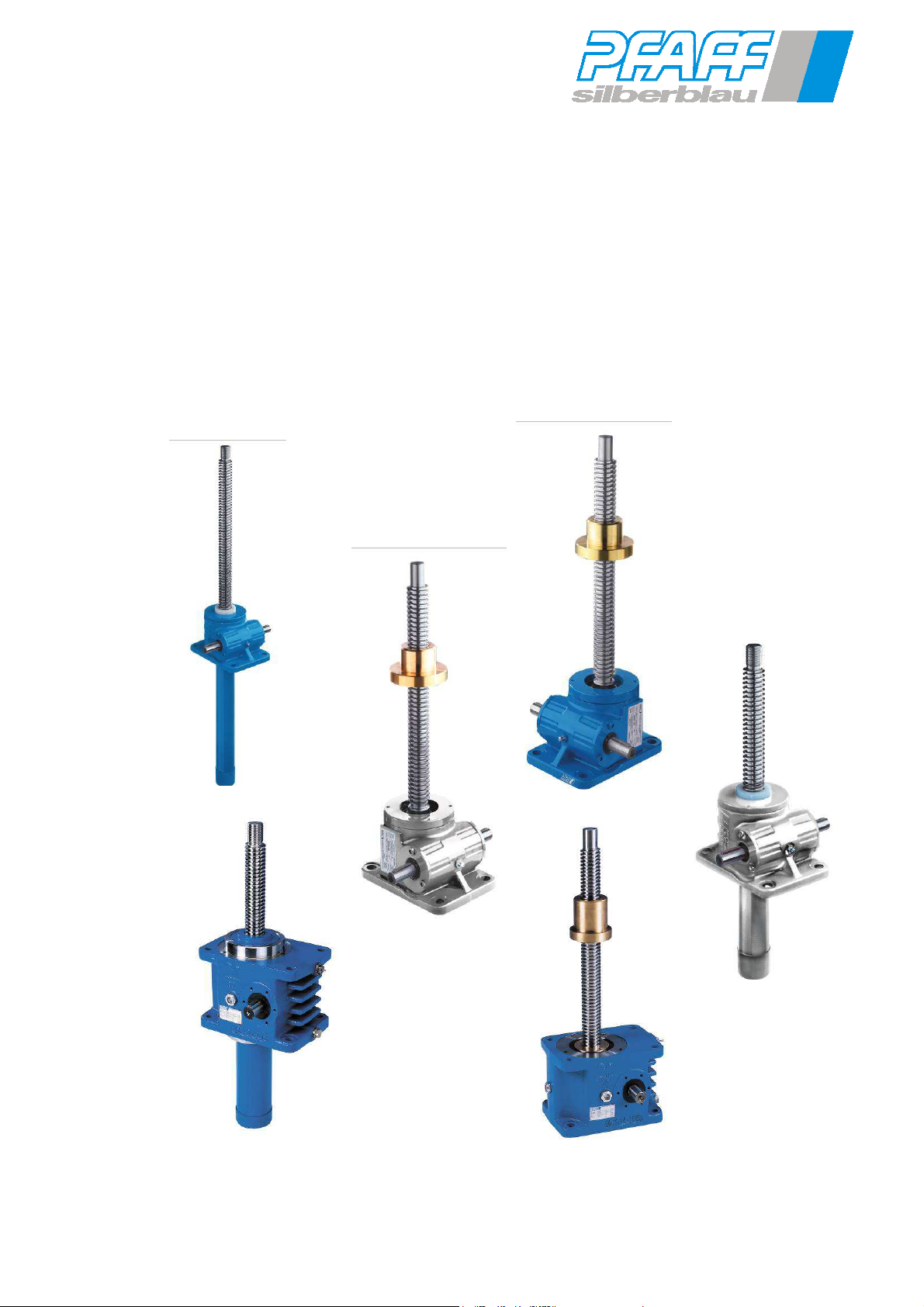
These operating instructions describe the Pfaff-silberblau worm gear screw jacks of the
SHE and HSE series. Please refer to our order confirmation or worm gear screw jack
compendium for details on the layout, design and permissible operating conditions for the
drives. Always observe and follow these operating instructions when using the equipment.
Read the operating instructions carefully before commissioning!
Observe the safety instructions!
Store document!
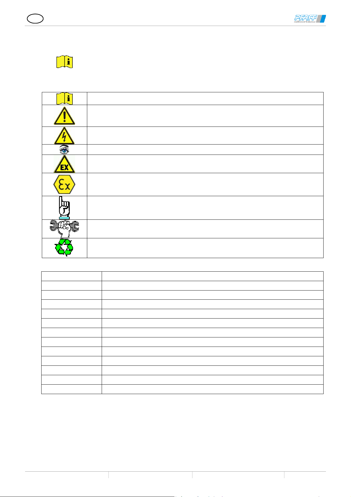
Practical information
Warning against a general hazard. Risk of injury due to neglect.
Warning against electrical voltage. Severe risk of injury due to neglect.
Information on the safety screw jacks
Danger of explosion
Important information for use in spaces with explosion hazards
T13.01.000.0000.0003
2019/04 Rev. Index E
Important information
Assembly and setting information
Disposal
SHE Worm gear screw jack
HSE High-performance worm gear screw jack
Type 1 (Ba1) Method of operation for type with lifting screw
Type 2 (Ba2) Method of operation for type with rotating screw
Specifications A = screw on housing cover side; B= screw on mounting surface side
Tr Trapezoidal thread spindle
Ku Ball screw spindle
S Buttress thread screw
P Screw pitch
DIN German industry standards
EN European norm
ISO International standards
ID Duty cycle in % / h
Subject to technical modifications Design changes under reserve Sous réserve de modifications techniques !
3
GB
Worm gear screw jacks are incomplete machines and are intended for installation in complete machines or
that are employed for converting rotational movement into longitudinal movement
the operating instructions, in the
Modifications to the screw jacks as well as the attachment of additional devices are only permitted with our
If stated in the order confirmation, the worm gear screw jacks with corresponding additional supplementary
e responsibility of the
The manufacturer of the complete system checks that the product in combination with the complete machine
or use in the existing Ex zone must be checked or assessed in
Worm gear screw jack SHE type1 and type2
High-performance screw jack HSE type1 and type2
T13.01.000.0000.0003
2019/04 Rev. Index E
1 Intended use
for assembly with several machines into a system.
They are drive elements
and for reducing speed or converting torque.
The drive systems may only be used for the designated purpose.
They may be used only under the application conditions specified in
technical documentation or in the order confirmation.
Operation outside the respective performance limitations / ambient conditions is not permitted.
Not suitable for use in explosive-atmosphere zones.
Not suitable for use in aggressive environments, if not constructed especially for these applications.
express and written authorisation.
Pay attention to the technical data and functional description!
equipment comply with the requirements of various standards and guidelines:
1.1 Screw jacks with safety devices for lifting platforms
in accordance with DIN EN 1570-1:2015-01; DIN EN 280:2014-02, DIN EN 1756, DIN EN 1493:2011-02
Screw jacks with safety devices such as limited pitch angle – safety nut, speed monitoring and/or wear monitoring
are designed or constructed according to the requirements of the applicable standard –
DIN EN 1570-1:2015-01 - Lifting tables
DIN EN 280:2014-02 - Elevating work platforms
DIN EN 1493:2011-02 – Vehicle lifts
DIN 56950-1:2012-05 – Event technology technical installations –
designed for installation in machines in accordance with the applicable standards.
The manufacturer of the complete system checks that the product in combination with the complete machine is in
conformity. The manufacturer of the complete system is responsible for conducting the risk assessment for the
complete system. The information in our operating instructions must be integrated in the instructions for the
complete machine.
Required prototype tests (experts' examinations) need to be carried out under th
manufacturer of the complete machine.
1.2 Worm gear screw jacks in accordance with ATEX guideline 2014/34/EC
are suited as components (2014/34/EC item 1 (3) for installation in machines for use in explosiveatmosphere zones as indicated by the ATEX marking.
For the ignition source analysis, the ATEX checklist must be filled out completely and submitted (www.pfaffsilberblau.com).
is ATEX conform, and is responsible for conducting the ignition source analysis for the complete system.
The information in our operating instructions must be integrated in the instructions for the complete machine.
The suitability of the ATEX components f
accordance with the ATEX marking, the order confirmation, conformity declaration and type plate.
Subject to technical modifications Design changes under reserve Sous réserve de modifications techniques !
4
GB
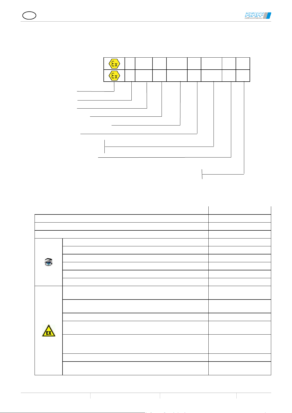
1.2.1 Marking in accordance with RL 2014/34/EC
Worm gear screw jack SHE type1 and type2
High-performance screw jack HSE type1 and type2
T13.01.000.0000.0003
2019/04 Rev. Index E
Gas
Dust
Ex-Symbol
Device group
Category
Ignition protection type
Equipment protection level (EPL)
Explosion group
Temperature class
Max. surface temperature
Equipment protection level
Equipment with partial certifikate,
CE Compliance is certified with Installation in a complete Equipment
2 Accident prevention guide
Observe the relevant instructions, regulations, and standards in the country of use. In Germany, these are
currently:
EC machinery directive 2006/42/EC
Machine safety DIN EN ISO 12100:2010
Lift devices DIN EN 1494:2009-05
Lifting tables DIN EN 1570-1:2015-01
Elevating work platforms DIN EN 280:2014-02
Loading platforms DINEN 1756
Vehicle lifts DIN EN 1493:2011-02
Stages and studios BGV C1
Stage mechanics, safety equipment DIN 56950-1:2012-05
EC guideline; Equipment and protective systems in potetially
explosive atmospheres (ATEX)
EC guideline; Improving the safety and health protection in
potentially explosive atmospheres
Explosion protection basics and methodology DIN EN 1127-1
Non-electric devices for use in explosive-atmosphere zones -
basics and requirements
Non-electric devices for use in explosive-atmosphere zones -
protection through constructional safety “c”, ignition source
monitoring "b"; liquid encapsulation “k”
Explosive atmosphere DIN EN 60079-0
Explosive atmosphere, projection, selection and set-up of
electrical systems
II 2G ck Ex h IIB T4 Gb U
II
2D c Ex h IIIB 135°C Db U
Rules and regulations
2014/34/EU
1999/92/EG (ATEX 137)
DIN EN ISO 80079-36
DIN EN ISO 80079-37
DIN EN 60079-14
Subject to technical modifications Design changes under reserve Sous réserve de modifications techniques !
5
GB
Worm gear screw jack SHE type1 and type2
High-performance screw jack HSE type1 and type2
T13.01.000.0000.0003
2019/04 Rev. Index E
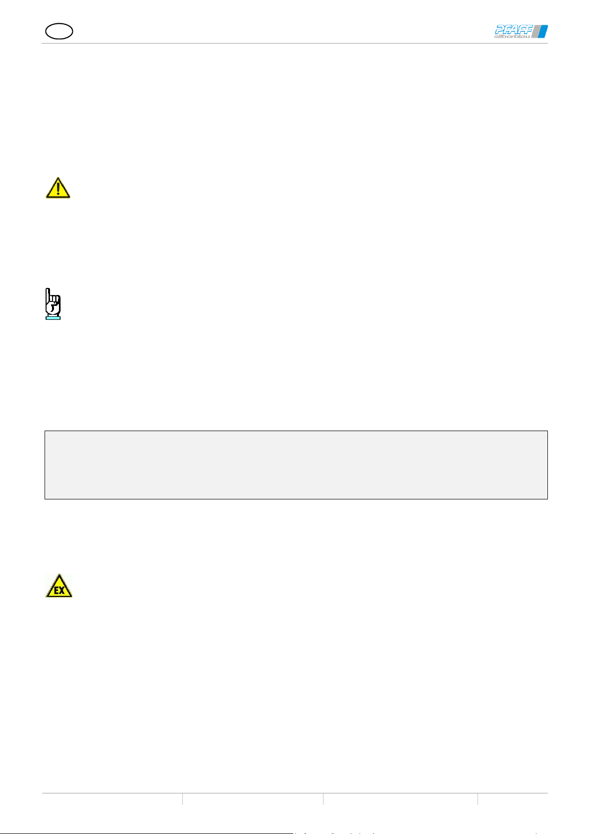
3 Safety information
3.1 General safety information
Operation, installation and maintenance may only be carried out by qualified personnel. The responsible
operator must be authorised in writing.
It is forbidden to transport people or to stay in the danger area of devices not designed for this purpose.
Exception: Screw jacks with safety features with corresponding intended use as described in Chapter 1.1
in the framework of the corresponding product standard.
Not suitable for use in explosive atmospheres!
Exception: Screw jacks are designed and marked as components for use in explosive-atmosphere
zones, as described in Chapter 1.2
Never reach into moving parts. Cover them or cut off access to them.
Do not remove or disable the safety devices.
The operational and safety limit switches must ensure that the lifting process is safely stopped at the end
positions.
To prevent contact with rotating/moving parts, attach protective covers (such as bellows, shaft caps) or
make those areas of the machine inaccessible.
Screw/Travelling nut must be fastened on-site or be turn-secured or equipped with the optional torsional
lock (max. screw torque according to technical documents). The construction must be able to bear the
screw torque securely.
Ball thread spindles and multi-geared trapezoidal thread spindles are not self-locking. An appropriate brake
device needs to be integrated into the system.
In the standard version, the screw does not have any protection against unintended skimming out of the
gear box (Ba1) or against the travelling nut driving out the screw. A protection against skimming needs to be
realised either on site or by worm gear screw jacks with mechanical end stops.
No lateral forces on the screw.
3.2 ATEX safety information
The owner of a system must ensure that the explosion-risk conditions are adhered to.
On-site layer thickness from surface coatings (e.g. lacquering) max. 2 mm (explosion group IIA and IIB) and
0.2 mm at explosion group IIC
Requirements for the reliable operation is a properly lubricated screw and a lift gear box provided with
lubrication.
The affects from knocks and bumps on the screw jack is not permitted.
Dust deposits are to be removed regularly.
Connect the screw jacks with potential equalisation (earth) and check the bleeder resistance (<106 Ohm).
Observe the speeds and permitted drive power output specified in the technical data when operating with
rotation speed control in the potentially explosive atmospheres.
On motorized drives, monitor the motor output with output gauges or otherwise temperature monitors (e.g.
thermistors (PTC) with evaluation device). Minimum requirements according to EN 13463-6 category 2IPL2; cat. 3 –IPL1.
Materials used must be resistant against the media.
The operator must count or measure the load cycles or operating hours and document them.
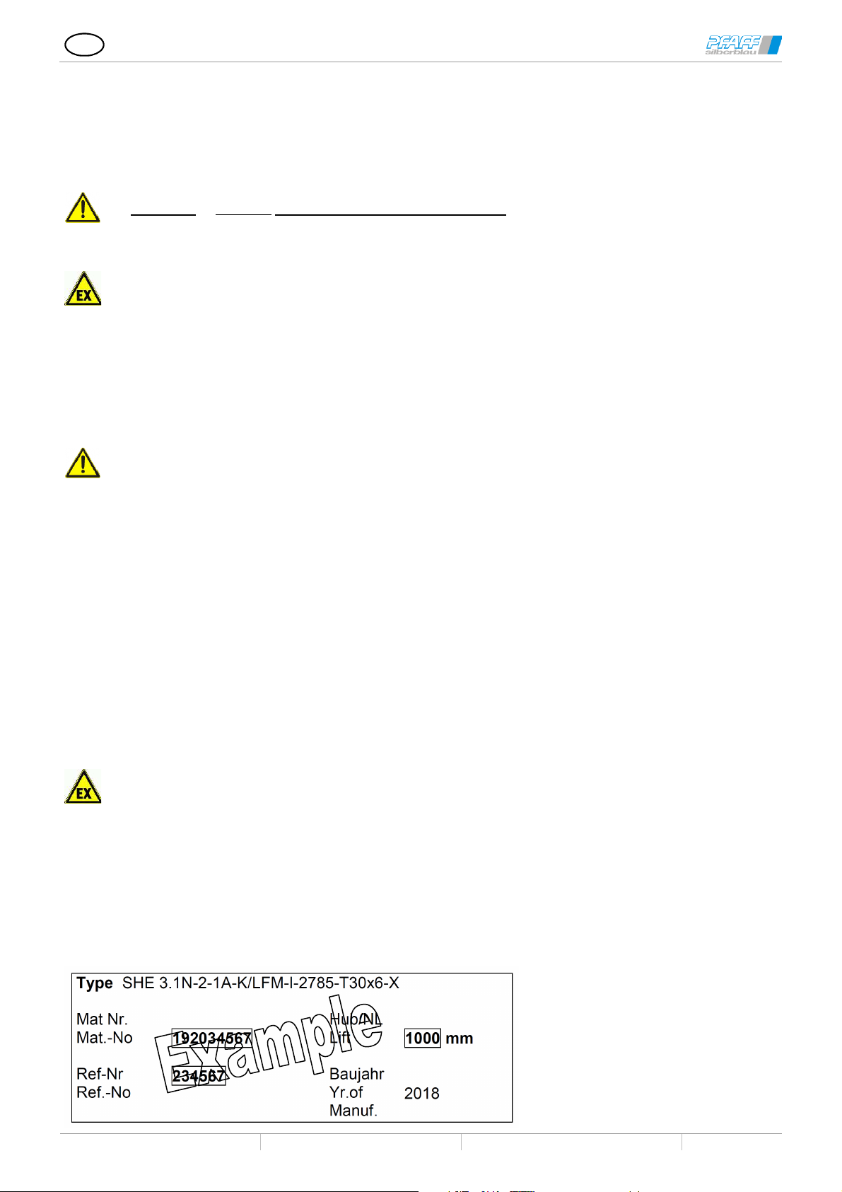
3.3 Type plate
Subject to technical modifications Design changes under reserve Sous réserve de modifications techniques !
6

GB
Worm gear screw jack SHE type1 and type2
High-performance screw jack HSE type1 and type2
T13.01.000.0000.0003
2019/04 Rev. Index E
3.3.1 Design variants
In the stated variants, the first letter refers to the top side refers to the head side of the screw jack and the
second letter refers to the opposite side.
K Short lid
H High lid
F Guide ring
S/SR Sheath tube
SA Round sheath tube with stop collar
Sf Sheath tube with guide ring
Si Sheath tube with inductive limit switches
Sm Sheath tube with mech. limit switches
Se Sheath tube with mechanical
end stop (protection against skimming)
SV Reinforced rough sheath tube
V/VK Torsional lock through Square sheath
tube
Vi Torsional lock with ind. limit switches
Vm Torsional lock with mech. limit switches
Ve Torsional lock with end stop
VP Torsional lock by feather key
VV Reinforced sheath tube
SFM-O Short safety nut
SFM-K Short safety nut in tube cap
SFM-L Long safety nut
SFM-E Long safety nut, el. monitored
SFM-D Long safety nut, el. monitored
with speed monitoring
Pivot lug version
P = swivelling version
P = swivelling version with end stop
Pm = swivelling version with mechanical operational
limit switches
Pi = swivelling version with inductive operational limit
switches
Q = swivelling version (bore head IV, rotated 90° to
worm shaft)
Qe = swivelling version (bore head IV, rotated 90° to
work shaft) with end stop
Qm = swivelling version (bore head IV, rotated 90° to
work shaft) with mech. end stops
Qi = swivelling version (bore head IV, rotated 90° to
work shaft) with mech. end stops
Travelling nut
LFM Standard travelling nut
LSF Travelling nut with spanner flat
LSA Travelling nut with spherical contact
surface
EFM Single-flange nut (Tr or Ku)
LWZ Travelling nut with swivel pin
Combined with safety nut
-K Short safety nut
-L Long safety nut
-E Long safety nut, el. monitored
4 Technical specifications
4.1 High-performance worm gear screw jacks HSE, standard and with safety features
Sizes in the HSE series 32 36.1 50.1 63.1 80.1 100.1 125.1 140 200.1
Max. lifting force [kN] 5 10 25 50 100 200 350 500 1000
Max. tension [kN] 5 10 25 50 100 178 350 500 1000
Spindle Tr1
Ratio N 4:1 5:1 6:1 7:1 8:1 8:1 10 2/3:1 10 2/3:1 13 1/3:1
Lift per rotation at ratio N [mm/U] 1,0 1,0 1,33 1,28 1,5 1,5 1,5 1,5 1,5
Ratio L 16:1 20:1 24:1 28:1 32:1 32:1 32:1 32:1 40:1
Lift per rotation at ratio L [mm/U] 0,25 0,25 0,33 0,32 0,375 0,375 0,5 0,5 0,5
Max. drive capacity2 at 20°C ambient
temp. and 20% DC/h
Max. drive capacity2 at 20°C ambient
temperature and 10% DC/h
Overall efficiency ratio N [%] See efficiency table compendium worm gear screw jack
Overall efficiency ratio L [%] See efficiency table compendium worm gear screw jack
Spindle efficiency [%] 42,5 43 40 36,5 39,5 35,5 34 30 28,5
Torque-capacity-rotation speed at 20%
ID/hr. and 20°C
Screw torque at max. lifting force [Nm] 7,4 18,4 80 190 478 1060 2600 4235 11115
Max. permit. torque on the drive shaft [Nm] 12,6 29,4 48,7 168 398 705 975 1640 4260
Max. permit. screw length at pressure
load
18x6 24x5 40x8 50x9 60x12 70x12 100x16 120x16 160x20
[kW] 0,60 0,90 1,5 2,3 3,6 4,8 7,7 10,2 17,9
[kW] 1,0 1,5 2,6 4,0 6,3 8,4 13,5 17,9 31
See power table compendium on worm gear screw jacks
[mm] See offset diagram compendium worm gear screw jacks
1 Also with Ku screw
2 Max. permissible values with BA 1 and Tr screw. Higher values are possible using BA 2 or Ku screws
Subject to technical modifications Design changes under reserve Sous réserve de modifications techniques !
7

GB
rotation speed at 20%
Lift per rotation at
Lift per rotation at
Max. drive capacity2 at 20°C ambient
Max. drive capacity2 at 20°C ambient
Overall efficiency
Overall efficiency
rotation speed at 20%
Max. permit. screw length at pressure
Worm gear screw jack SHE type1 and type2
High-performance screw jack HSE type1 and type2
T13.01.000.0000.0003
2019/04 Rev. Index E
4.2 Worm gear screw jack SHE standards and with safety features
Model series SHE unit size
Max. lifting capacity dyn/stat [kN] 5 10 30/45 50/75 100/150 200
Max. tensile load dyn/stat [kN] 5 10 30/45 50/75 99 178/200
Screw Tr3 18x6 24x5 30x6 40x7 60x12 70x12
Ratio N 10:1 5:1 6:1 6:1 7 2/3:1 8:1
Lift per rotation at
ratio N
Ratio L 20:1 20:1 24:1 24:1 24:1 24:1
Lift per rotation at
ratio L
Max. drive capacity4 at 20°C ambient
temp. and 20% DC/h
Max. drive capacity2 at 20°C ambient
temperature and 10% DC/h
Overall efficiency
ratio N
Overall efficiency
ratio L
Spindle efficiency [%] 54 43 40 36,5 39,5 37,5
Torque-capacity-
ID/hr. and 20°C
Screw torque at max. lifting force [Nm] 8,8 18,4 60 153 702 1009
Max. permit. torque on the drive shaft [Nm] 12 29,4 46,5 92 195 280
Max. permit. screw length at pressure
load
Model series SHE unit size
Max. lifting force
Max. tension
Screw Tr1
Ratio N
ratio N
Ratio L
ratio L
temperature and 20% DC/h
temperature and 10% DC/h
ratio N
ratio L
Spindle efficiency
Torque-capacityID/hr. and 20°C
Screw torque at max. lifting force
Max. permit. torque on the drive shaft
load
BG 0,5 1.1 3.1 5.1 15.1 20.1
[mm/U] 0,60 1,0 1,0 1,167 1,565 1,50
[mm/U] 0,30 0,25 0,25 0,292 0,50 0,5
[kW] 0,17 0,35 0,65 1,15 2,7 3,8
[kW] 0,25 0,55 0,9 1,65 3,85 5,4
[%] 31 29 27 24 27 24
[%] 24 20 19 16 17 17
See power table compendium on worm gear screw jacks
[mm] See offset diagram compendium worm gear screw jacks
BG 25 35 50.1 75 100.1 150 200.1
[kN] 250 350 500 750 800/1000 1500 2000
[kN] 250 350 500 750 800/1000 1500 -
90x16 100x16 120x16 140x20 160x20 190x24 220x28
10 2/3:1 10 2/3:1 10 2/3:1 12:1 12:1 19:1 17,5:1
[mm/U] 1,50 1,50 1,50 1,667 1,667 1,263 1,60
32:1 32:1 32:1 36:1 36:1 -
[mm/U] 0,5 0,5 0,5 0,556 0,556 -
[kW] 5,0 6,0 7,4 9,0 12,5 18,5
[kW] 7,2 8,6 10,4 12,6 17,5 26
[%] 22 21 15 18 15 15
[%] 15 14 10 12 9 -
[%] 36,5 34 30 31,6 28,5 28,8 29
See power table compendium on worm gear screw jacks
[Nm] 1725 2600 4235 7550 11115 19850
[Nm] 480 705 840 2660 2660 4260
[mm] See offset diagram compendium worm gear screw jacks
3Also with Ku screw
4 Max. permissible values with BA 1 and Tr screw. Higher values are possible using BA 2 or Ku screws
Subject to technical modifications Design changes under reserve Sous réserve de modifications techniques !
8
 Loading...