


MADL*01 Series
Table of contents
 Loading...
Panasonic MADL*01 Series, MBDL*21 Series, MADL*11 Series, MADL*05 Series, MBDL*25 Series Reference Specifications
...
No.SX-DSV03015
REFERENCE SPECIFICATIONS
MODEL
Product Name: AC servo driver
Part Number : MINAS-A6 series (Basic type)
Issued on Sept. 1, 2015
Revised on Sept. 14, 2016
Motor Business Unit, Electromechanical Control Business Division
Automotive & Industrial Systems Company, Panasonic Corporation
7-1-1 Morofuku , D aito-City, Osaka 574-0044 Japan

No. SX-DSV03015
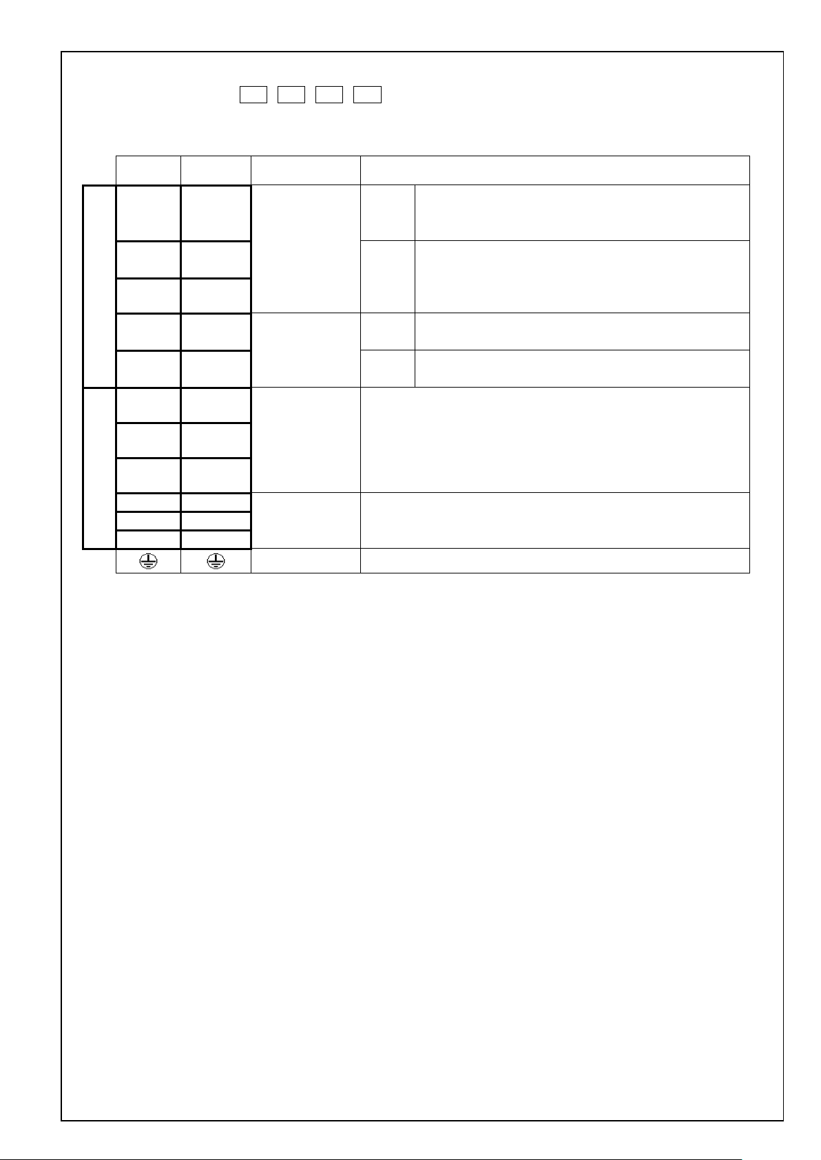
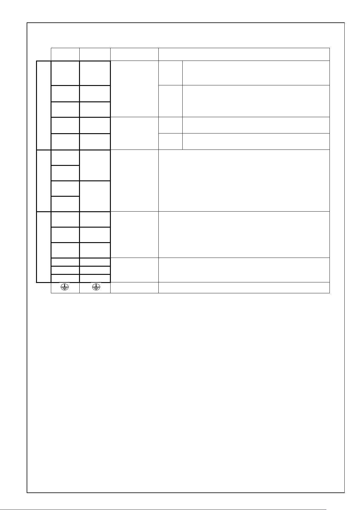
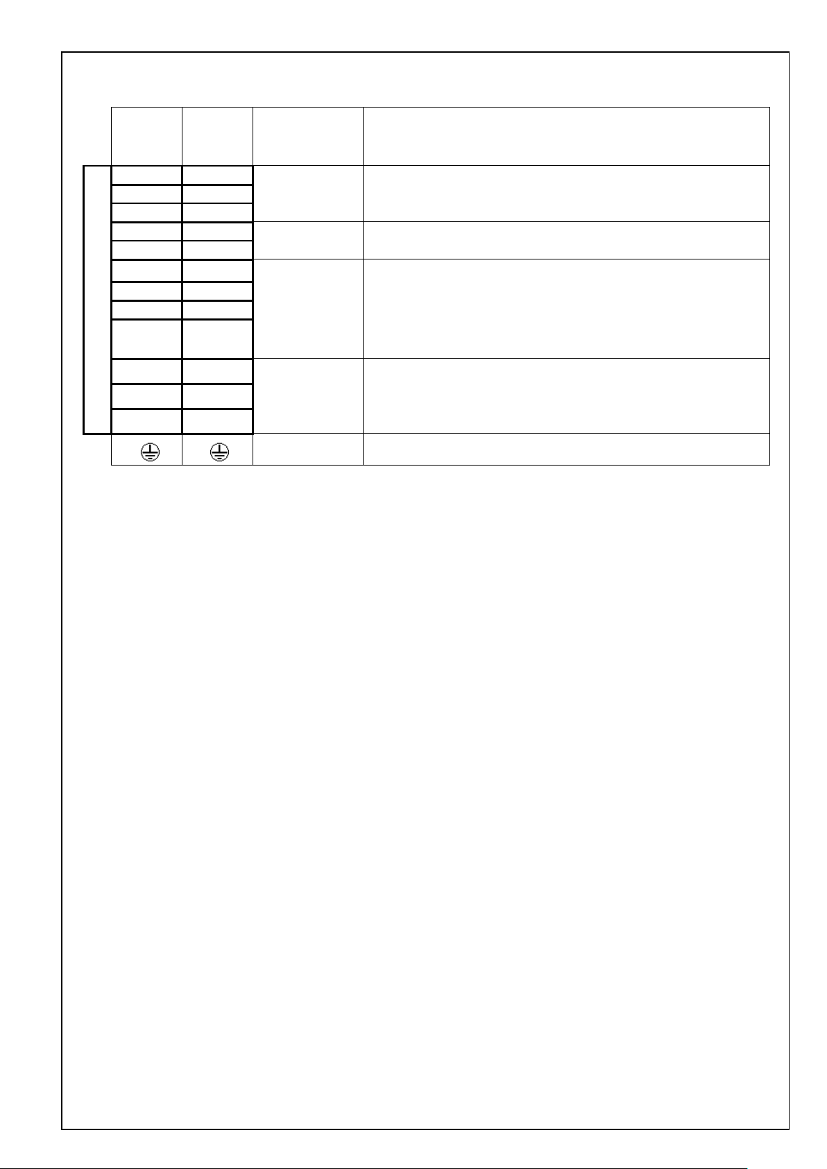
REVISIONS
Date Page Rev. Description Signed
Spt. 1, 2015
Nov. 1, 2015
Sept.14,2016
P1, P3,P53, P65
P5
P56 ADDED THE HARMONIC SUPPRESSION MEASURES
- NEWLY ISSUED -
- 1.0 DEFAULT VALUE OF THE PARAMETERS CHANGED -
P1 2.0 UPDATE THE MODEL DESIGNATION CODE -
P1 CHANGED THE NAME OF COMPANY
ADDED THE MODEL OF MEDLN93SE
ADDED THE FUNCTIONS
P63~65
CORRECT THE INRUSH CURRENTS AT CONTROL POWER SUPPLY
Motor Business Unit, Panasonic Corporation
No. SX-DSV03015
Contents
1. Scope ································································································································· 1
2. Model designation code ············································································································ 1
3. Product line-up ······················································································································ 2
4. General specifications ·············································································································· 4
4-1 General specification ········································································································· 4
4-2 Specifications by model ······································································································ 5
5. Appearance and part names ········································································································ 6
6. Configuration of connectors and terminal blocks ··············································································· 11
6-1 Power connector XA , XB , XC , XD and terminal block ························································ 11
6-2 USB connector X1 ··········································································································· 15
6-3 Parallel I/O connector, X4 ·································································································· 16
6-4 Encoder connector X6 ······································································································· 20
7. Dimensions ·························································································································· 23
8. Wiring ································································································································ 35
8-1 Used cables and maximum cable lengths ·················································································· 35
8-2 Various connectors ············································································································ 35
8-3 Precautions for wiring ········································································································ 36
9. Compliance with global standards ································································································ 49
9-1 Conforming standards ········································································································ 49
9-2 European EC directive········································································································ 49
9-3 Peripheral device configuration ····························································································· 50
9-4 List of peripheral devices applicable to servo driver ····································································· 53
9-5 Compliance with UL stand a r d ······························································································· 55
9-6 Radio waves act (South Korea) precautions ··············································································· 56
9-7 Compliance with SEMI F47 instantaneous stop standard ······························································· 56
9-8 Harmonic suppression measures ···························································································· 56
10. Safety precautions ················································································································· 57
11. Life and warranty ·················································································································· 61
11-1 Life expectancy of the driver ······························································································· 61
11-2 Typical life ··················································································································· 61
11-3 Warranty period ·············································································································· 61
12. Others ······························································································································· 62
13. Specification for each model ····································································································· 63
The maximum value of torque limit setup
Default value of the parameters
Motor Business Unit, Panasonic Corporation

Custom specification (Alphanumeric)
Size
1. Scope
These specifications relate to the servo driver for the AC servo system that is comprised of the AC servo motor
manufactured and supplied by Motor Business Unit, Electromechanical Control Business Division, Automotive &
Industrial amplifier Systems Company, Pan ason ic C orporat ion .
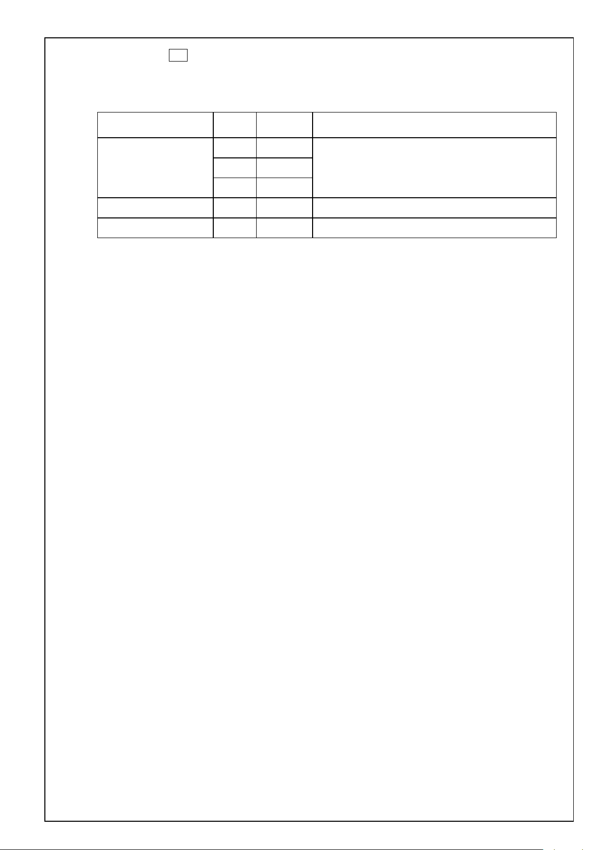
2. Model designation code
Notation of the machine designation code is as follows:
A : Size A
B : Size B
C : Size C
D : Size D
E : Size E
F : Size F
AC Servo drive
L : A6 series
Safety function
N : Without functional safety
Maximum instantaneous
output current
0 : 6 A
1 : 8 A
2 : 12 A
3 : 22 A
4 : 24 A
5 : 40 A
8 : 60 A
9 : 80 A
A : 100 A
B : 120 A
1 2 3 4 5 6 7 8 9 10 11 12
M A D L N 1 5 S E * * *
User Interface
• Rotary type
Power supply voltage
No. SX-DSV03015 - 1 -
E : Basic type
1 : Single phase 100 V
3 : 3 phase 200 V
5 : Single or 3 phase 200 V
Motor Business Unit, Panasonic Corporation
No. SX-DSV03015 - 2 -
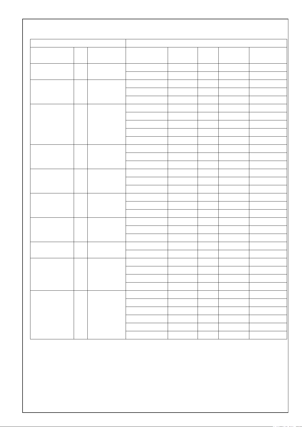
3. Product line-up
Servo driver Motor used
Model Size
Power supply
input
Model
Voltage
specification
Rated
output
Rated speed
MADLN01SE A Single MSMF5AZL1** 100 V 50 W 3000 r/min 7 cores, 23 bits
100 V MHMF5AZL1** 100 V 50 W 3000 r/min
MADLN11SE A Single MSMF011L1** 100 V 100 W 3000 r/min
100 V MQMF011L1** 100 V 100 W 3000 r/min
MHMF011L1** 100 V 100 W 3000 r/min
MADLN05SE A Single / 3 phase MSMF5AZL1** 200 V 50 W 3000 r/min
200 V MHMF5AZL1** 200 V 50 W 3000 r/min
MSMF012L1** 200 V 100 W 3000 r/min
MQMF012L1** 200 V 100 W 3000 r/min
MHMF012L1** 200 V 100 W 3000 r/min
MADLN15SE A Single / 3 phase MSMF022L1** 200 V 200 W 3000 r/min
200 V MQMF022L1** 200 V 200 W 3000 r/min
MHMF022L1** 200 V 200 W 3000 r/min
MBDLN21SE B Single MSMF021L1** 100 V 200 W 3000 r/min
100 V MQMF021L1** 100 V 200 W 3000 r/min
MHMF021L1** 100 V 200 W 3000 r/min
MBDLN25SE B Sin gle / 3 phase MSMF042L1** 200 V 400 W 3000 r/min
200 V MQMF042L1** 200 V 400 W 3000 r/min
MHMF042L1** 200 V 400 W 3000 r/min
MCDLN31SE C Single MSMF041L1** 100 V 400 W 3000 r/min
100 V MQMF041L1** 100 V 400 W 3000 r/min
MHMF041L1** 100 V 400 W 3000 r/min
MCDLN35SE C Single / 3 phase MSMF082L1** 200 V 750 W 3000 r/min
200 V MHMF082L1** 200 V 750 W 3000 r/min
MDDLN45SE D Single / 3 phase MGMF092L1** 200 V 850 W 1500 r/min
200 V MSMF092L1** 200 V 1.0 kW 3000 r/min
MDMF102L1** 200 V 1.0 kW 2000 r/min
MHMF102L1** 200 V 1.0 kW 2000 r/min
MDDLN55SE D Single / 3 phase MHMF092L1** 200 V 1.0 kW 3000 r/min
200 V MSMF102L1** 200 V 1.0 kW 3000 r/min
MGMF132L1** 200 V 1.3 kW 1500 r/min
MSMF152L1** 200 V 1.5 kW 3000 r/min
MDMF152L1** 200 V 1.5 kW 2000 r/min
MHMF152L1** 200 V 1.5 kW 2000 r/min
Encoder
specification
7 cores, 23 bits
7 cores, 23 bits
7 cores, 23 bits
7 cores, 23 bits
7 cores, 23 bits
7 cores, 23 bits
7 cores, 23 bits
7 cores, 23 bits
7 cores, 23 bits
7 cores, 23 bits
7 cores, 23 bits
7 cores, 23 bits
7 cores, 23 bits
7 cores, 23 bits
7 cores, 23 bits
7 cores, 23 bits
7 cores, 23 bits
7 cores, 23 bits
7 cores, 23 bits
7 cores, 23 bits
7 cores, 23 bits
7 cores, 23 bits
7 cores, 23 bits
7 cores, 23 bits
7 cores, 23 bits
7 cores, 23 bits
7 cores, 23 bits
7 cores, 23 bits
7 cores, 23 bits
7 cores, 23 bits
7 cores, 23 bits
7 cores, 23 bits
7 cores, 23 bits
Motor Business Unit, Panasonic Corporation
No. SX-DSV03015 - 3 -
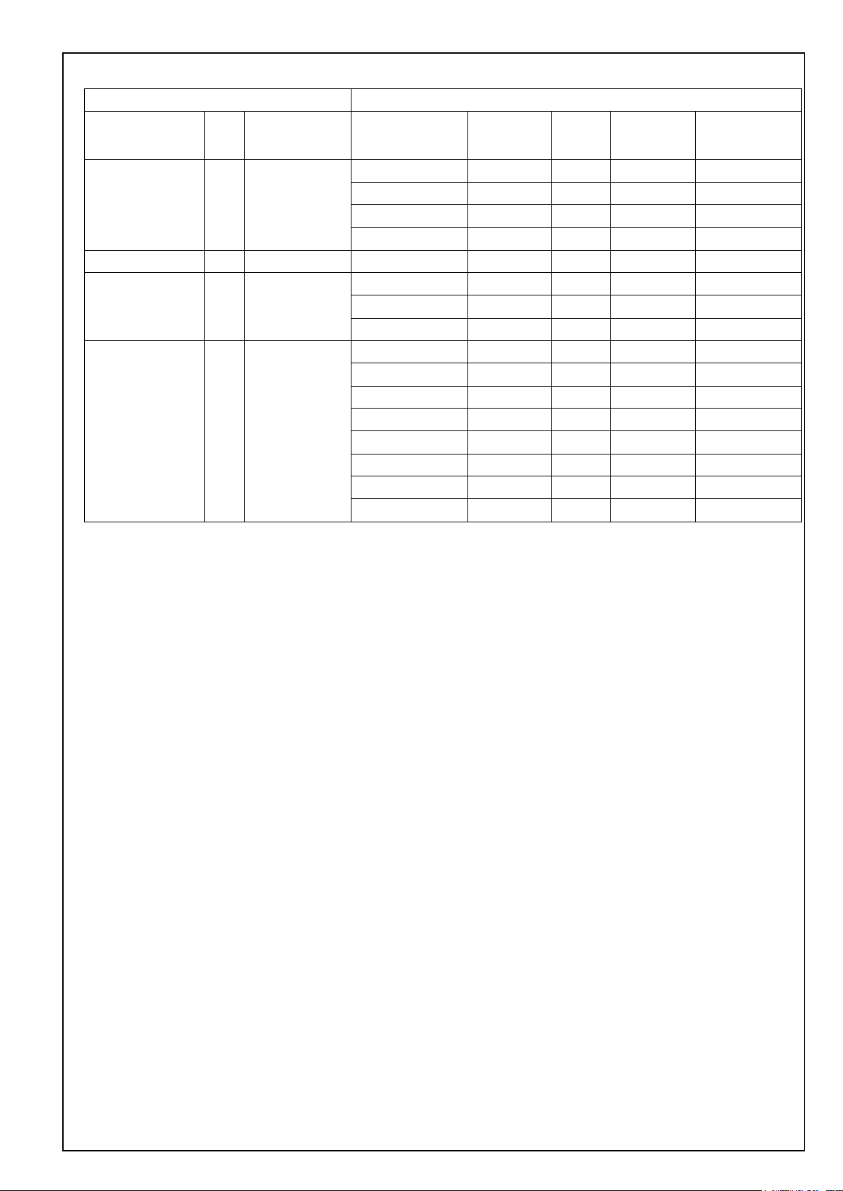
Servo driver Motor used
Model Size
Power supply
input
Model
Voltage
specification
Rated
output
Rated speed
MEDLN83SE E 3 phase MGMF182L1** 200 V 1.8 kW 1500 r/min 7 co r es, 23 bits
200 V MSMF202L1** 200 V 2.0 kW 3000 r/min 7 cores, 23 bits
MDMF202L1** 200 V 2.0 kW 2000 r/min 7 cores, 23 bits
MHMF202L1** 200 V 2.0 kW 2000 r/min 7 cores, 23 bits
MEDLN93SE E 3 phase 200 V MGMF242L1** 200 V 2.4 kW 1500 r/min 7 cores, 23 bits
MFDLNA3SE F 3 phase MSMF302L1** 200 V 3.0 kW 3000 r/min 7 cores, 23 bits
200 V MDMF302L1** 200 V 3.0 kW 2000 r/min 7 cor es, 23 bits
MHMF302L1** 200 V 3.0 kW 2000 r/min 7 cores, 23 bits
MFDLNB3SE F 3 phase MGMF292L1** 200 V 2.9 kW 1500 r/min 7 co r es, 23 bits
200 V MSMF402L1** 200 V 4.0 kW 3000 r/min 7 co res, 23 bits
MDMF402L1** 200 V 4.0 kW 2000 r/min 7 cor es, 23 bits
MHMF402L1** 200 V 4.0 kW 2000 r/min 7 cores, 23 bits
MGMF442L1** 200 V 4.4 kW 1500 r/min 7 cor es, 23 bits
MSMF502L1** 200 V 5.0 kW 3000 r/min 7 cores, 23 bits
MDMF502L1** 200 V 5.0 kW 2000 r/min 7 cor es, 23 bits
MHMF502L1** 200 V 5.0 kW 2000 r/min 7 cores, 23 bits
Encoder
specification
Motor Business Unit, Panasonic Corporation

No. SX-DSV03015 - 4 -
Storage temperature: -20 – 65 degrees C (Max.temperature gu arantee : 80 degrees C for 72 hours no condensation*)
Height above the sea
Height above the sea level: 1000 meters or less
Vibration
5. 88 m/s2 or less, 10 – 60 Hz
Insulation voltage
Resistant to 1500 V AC between primary power supply and ground for a minute (Sensed current: 20 mA)
Control method
IGBT PWM method, sinusoidal drive
Encoder feedback
23Bit(resolution:8388608) 7cores-serial absolute encoder
Function of each multi-funct i o n i np ut is assigned by the parameter.
Function of each multi-function output is assigned by the parameter.
Analogue signal
Output
2 outputs for analog monitor
High speed line driver interface can be connected.
collector output also available for Z or EXZ signal
Communication
USB
USB interface to connect to computers for parameter setting or status monitoring.
Front panel
5 key switches, 6-digit 7-se g ment LED
Regeneration
Size A, B: External r egen resistor only Size C - F: Built-in regen resistor (External regen is also available)
Dynamic brake
Size A - F: Built-in
4. General specifications
4-1 General specification
100 V
Input
power
supply
200 V
Operation conditions
Basic specifications
Control signal
Main circuit power
Control circuit power Single phase 100 - 120 V
Main circuit
power
Control circuit
power
Temperature
Humidity Operation and storage humidity 20 - 85 % RH or less (no condensation*)
A - D
E - F 3 phase 200 - 240 V
A - D
E - F Single phase 200 - 240 V
Input
Output
Multi-function input x 10
Multi-function output x 5 + dedicated output x 1 (alarm output)
Single phase 100 - 120 V
Single/3 phase 200 - 240 V
Single phase 200 - 240 V
+ 10%
50/60 Hz
- 15%
+ 10 %
50/60 Hz
- 15 %
+ 10 %
50/60 Hz
- 15 %
+ 10 %
50/60 Hz
- 15 %
+ 10 %
50/60 Hz
- 15 %
+ 10 %
50/60 Hz
- 15 %
Operation tempera ture: 0 - 55 degrees C (no freezing)
2 inputs
Input
Pulse signal
Output
Control mode
Please note that condensation tend to occur when temperature fall.
Both open collector and line driver interface can be connected.
4 outputs
Line driver output for encoder pulses (A/B/Z signal) or external feedba c k pulses (EXA/EXB/EXZ sig nal) open
Selectable from the fo llowing 3 modes by parameter:
[1]position cont rol [2]velocity control [3]position/velocity c ontrol
Motor Business Unit, Panasonic Corporation
No. SX-DSV03015 - 5 -
Deviation counter clear, command pulse input inhibition, command division/multiplication switching,
vibration suppression control sw itc hing, etc.
1/1000 to 8000 times
Smoothing Filter
Available
ion origin return invalidation sett ing is s et to
invalid)
Internal command velocity selection 1, Internal command velocity selection 2, Internal command velocity selection 3,
speed zero clamp, etc.
Control output
Speed arrival, etc.
0 to 10s/1000 r/min r/min Setting is possible for acceleration and deceleration respectively. S shaped
acceleration/deceleration is possible.
Velocity command filter
Available
Block operation
Not available
This function identifies the load inertia real-time and automatically sets up the gain that meets the stiffness setting
when the motor is running with ho st and inte r nal driver operation co mmands.
Overvoltage, undervoltage, overspeed, overload, overheat, overcurrent, encoder failure, positional overdeviation,
command pulse division, EEPROM failure, etc.
Control input
Control output Positioning co mpletion, etc.
Max command pulse
frequency
Command pulse input
Pulse input
Vibration suppression control Maximum of 3 may be used simultaneously
Position control
Model type vibration damping filter Maximum of 2 may be used simultaneously
2 degrees of freedom control Available
Load fluctuation suppression control Available
mode
Command pulse scaling
(Electronic gear)
500 K[pulse/s] (w hen using the photo coup ler input)
8 M[pulse/s] (when using the line receiver input of A-phase /B-phase)
Differential inp ut . D iffe rential input can be selected by parameters. ((1) Positive direction/ negative direction,
(2) A-phase/B-phase (3) Command/ direction)
Although electronic g ear rati o of the en coder resolu tion (num erator) and command number of pulses per revoluti on of the
motor (denominator) can be arbitrarily set in the range of 1 to 223 f or th e numerator and in the rang e of 1 to 223 f or the
denominator, this product should be u sed within the afor ementioned range.
Primary delay filter or FIR filter is selectable for command input.
Position compare output function
Block operation Available
Contro l i np u t
Function
Internal velocity command It is possible to switch 8 speeds of internal velocity with control input.
Soft start/down function
Speed zero clamp I nternal velocity command can be clamped to 0 with speed zero clamp input.
Velocity control
2 degrees of freedom control Available
Load fluctuation suppression control Available
Position compare output function Not available
Auto-tuning
Pulse signal output division function Number of pulses can be arbitrarily set. (However, the number of encoder pulses is the maximum number.)
Protectio n f u nction
Alarm data trace back function Reference of history of alarm data is available.
Common
Infinite rotation absolute funct ion Available
Deterioration diagnosis function Available
[Condition] Block operation valid setting
Return to origin completed state in incre me nt mo de (when block operat
4-2 Specifications by model
Refer to specification for each model.
Motor Business Unit, Panasonic Corporation
5. Appearance and part names
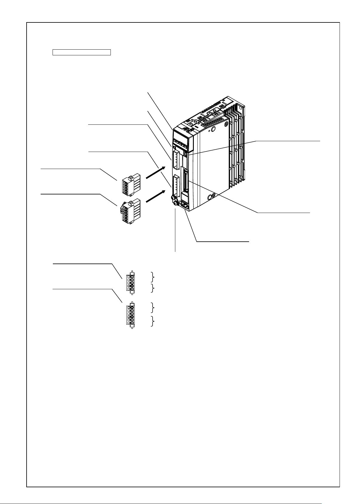
100 V,200 V size A, B
XA:Power supply input connection
05JFAT-SAXGGKK-A (JST)
(or equivalent)
Front panel
Charge lamp
XA: Power supply input
S05B-F32SK-GGXR (JST)
(or equivalent)
XB: Motor output
S06B-F32SK-GGXR (JST)
(or equivalent)
No. SX-DSV03015 - 6 -
X1:USB connection
UB-M5BR-S14-4S(LF)(SN) (JST)
(or equivalent)
XB:Motor connection
06JFAT-SAXGGKK-A (JST)
(or equivalent)
XA:Power supply input connection
XB:Motor connection
L1
L2
L3
L1C
L2C
P
N
B
U
V
W
Earth connection screw
Main power supply
input
Control power supply
input
Regenerative resistor
connection
Motor output
X6:Encoder connection
3E106-223AKV(3M)
(or equivalent)
X4:Parallel I/O connection
DF02R050NA2 (JAE)
(or equivalent)
Motor Business Unit, Panasonic Corporation
No. SX-DSV03015 - 7 -
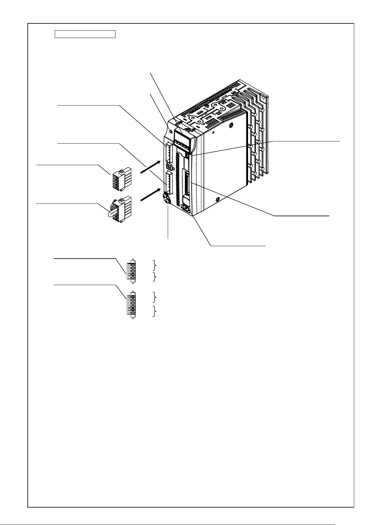
100 V,200 V size C, D
Front panel
Charge lamp
XA: Power supply input
S05B-F32SK-GGXR (JST)
(or equivalent)
XB: Motor output
S06B-F32SK-GGXR (JST)
(or equivalent)
XA:Power supply input connection
05JFAT-SAXGGKK-A (JST)
(or equivalent)
XB:Motor connection
06JFAT-SAXGGKK-A (JST)
(or equivalent)
XA:Power supply input connection
XB:Motor connection
Earth connection screw
L1
L2
L3
L1C
L2C
P
RB
B
U
V
W
Main power supply
input
Control power supply
input
Regenerative resistor
connection
Motor output
X6:Encoder connection
3E106-223AKV(3M)
(or equivalent)
X1:USB connection
UB-M5BR-S14-4S(LF)(SN) (JST)
(or equivalent)
X4:Parallel I/O connection
DF02R050NA2 (JAE)
(or equivalent)
Motor Business Unit, Panasonic Corporation
No. SX-DSV03015 - 8 -
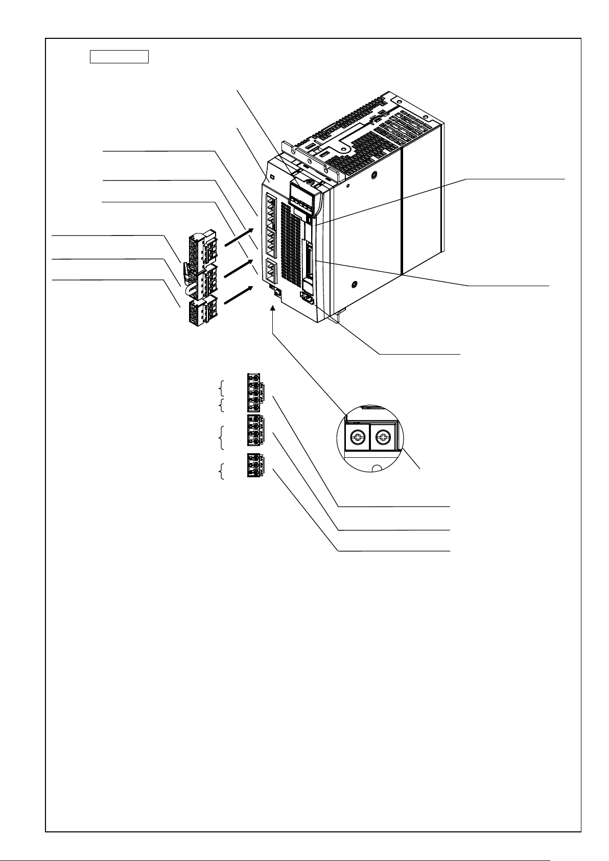
X1:USB connection
UB-M5BR-S14-4S(LF)(SN) (JST)
(or equivalent)
X4:Parallel I/O connection
DF02R050NA2 (JAE)
(or equivalent)
X6:Encoder connection
3E106-223AKV(3M)
(or equivalent)
Charge lamp
Front panel
Earth connection screw
XA:Power supply input connection
XC:Regenerative resistor connection
XB:Motor connection
XA:Power supply input connection
05JFAT-SAXGSA-L (JST)
(or equivalent)
XC:Regenerative resistor connection
04JFAT-SAXGSA-L (JST)
(or equivalent)
XB:Motor connection
03JFAT-SAXGSA-L (JST)
(or equivalent)
XA: Power supply input
S05B-JTSLSK-GSANXR (JST)
(or equivalent)
XB: Motor output
S03B-JTSLSK-GSANXR (JST)
(or equivalent)
XC: Regenerative resistor connection
S04B-JTSLSS-GSANXR (JST)
(or equivalent)
L1
L2
L3
L1C
L2C
P
RB
B
N
U
V
W
Main power supply
input
Control power supply
input
Regenerative resistor
connection
Motor output
200 V size E
Motor Business Unit, Panasonic Corporation

No. SX-DSV03015 - 9 -
200 V size F
Front panel
Charge lamp
X1:USB connection
UB-M5BR-S14-4S(LF)(SN) (JST)
(or equivalent)
X4:Parallel I/O connection
DF02R050NA2 (JAE)
(or equivalent)
Earth connection screw
Main power supply
input
Control power supply
input
Regenerative resistor
connection
Motor output
L1
L2
L3
L1C
L2C
P
RB
B
N
U
V
W
X6:Encoder connection
3E106-223AKV(3M)
(or equivalent)
Motor Business Unit, Panasonic Corporation

No. SX-DSV03015 - 10 -
Model number
Serial number
e.g.):
P 1 5 0 7 0 0 0 1 N
Lot number
Month of
production
Year of production
(Lower 2 digit of AD year)
Input/output voltage
Number of phase
Rated input/output
current
Input/output
frequency
Rated output of
applicable motor
QR code
standard mark
Country of
origin
Manufacture date
e.g.):
2 0 1 5 0 7 0 1
Manufacture date
Manufacture month
Manufacture year
Name plate
Motor Business Unit, Panasonic Corporation
No. SX-DSV03015 - 11 -
Connector
pin No.
Terminal
symbol
+ 10 %
- 15 %
Use L1 and L3 terminal for single phase input
+ 10 %
- 15 %
+ 10 %
- 15 %
+ 10 %
- 15 %
When a trip happens due to a regenerative load protection error, connect
3
U
2 V 1
W
6. Configuration of connectors and terminal blocks
6-1 Power connector XA , XB , XC , XD and terminal block
[1] Size A, B of 100 V and 200 V system
XA
XB
5 L1
4 L2
3 L3 Use L1 and L3 terminal for single phase input
2 L1C
1 L2C 200 V Single phase 200-240 V
6 P
5 N
4 B
Name Description
Single phase 100-120 V
Single or 3 phase 200-240 V
an external regenerative resistor (prepared by customer) between P and
B.
U: U phase V: V phase W: W phase
Main power
supply input
Control power
supply input
Regen resistor
connection
Motor connection
Earth
100 V
200 V
100 V Single phase 100-120 V
Then, specify the extern al regenerative resistor for the parameter
Pr0.16.
Do not connect N terminal.
Connect each phase of the motor winding.
Earth terminal for grounding
50/60 Hz input
50/60 Hz input
50/60 Hz input
50/60 Hz input
* Tighten the earth screws M4 with the 0.7-0.8 Nm torque respectively.
Motor Business Unit, Panasonic Corporation
No. SX-DSV03015 - 12 -
Connector
pin No.
Terminal
symbol
+ 10 %
- 15 %
Use L1 and L3 terminal for single phase input
+ 10 %
- 15 %
+ 10 %
- 15 %
+ 10 %
- 15 %
Normally, short out the circuit between B and RB. (Sizes C, D)
3
U
2 V 1
W
[2] Size C, D of 100 V and 200 V system
Name Description
XA
XC
XB
5 L1
Main power s upply
4 L2
3 L3 Use L1 and L3 terminal for single phase input
2 L1C
1 L2C 200 V Single phas e 200 – 240 V
4
N
3
2
P
1
6 P
5 RB
4 B
input
Control power
supply input
- Do not connect.
Regen resistor
connection
100 V
200 V
100 V Single phase 100-120 V
When a trip happens due to a re ge ner ati ve load prote c ti on e rror , o pen t h e
Then, specify the extern al regenerative resistor for the parameter
Pr0. 16.
Single phase 100-120 V
Single or 3 pha se 20 0 – 240 V
circuit between B and RB and conn ect an external regenerative resistor
(prepared by customer) bet w een P and B.
50/60 Hz input
50/60 Hz input
50/60 Hz input
50/60 Hz input
Motor connection
Earth
Connect each phase of the motor winding.
U: U phase V: V phase W: W phase
Earth terminal for grounding
* Tighten the earth screws M4 with the 0.7-0.8 Nm torque respectively.
Motor Business Unit, Panasonic Corporation

No. SX-DSV03015 - 13 -
Connector
pin No.
Terminal
symbol
5
L1
4
L2 3 L3
2
L1C
1
L2C
3
U
2 V 1
W
[3] Size E of 200 V system
Name Description
XA
XC
XB
4 P
3 RB
2 B
1 N
Earth Earth terminal for grounding
Main power s upply
input
Control power
supply input
Regen resistor
connection
Motor connection
200 V 3 phase 200 - 240 V
200 V Single phase 200 - 240 V
Normally, short out the circuit between RB and B.
When a trip happens due to a regenerative load protection error, open the
circuit between RB and B and connect an external regenerative resisto r
(prepared by customer) between P and B.
Then, specify the external regenerative resistor for parameter Pr0. 1 6.
Do not connect N terminal.
Connect each phase of the motor winding.
U: U phase V: V phase W: W phase
+ 10 %
- 15 %
+ 10 %
- 15 %
50/60 Hz input
50/60 Hz input
* Tighten the earth screws M4 with the 0.7-0.8 Nm torque respectively.
Motor Business Unit, Panasonic Corporation
No. SX-DSV03015 - 14 -
Terminal
bottom)
1
L1
2
L2 3 L3 4 L1C
- 15 %
5
L2C
Normally, short out the circuit between RB and B.
When a trip happens due to a regenerative load protection error, open the
7
RB 8 B
[4] Size F of 200V system
Terminal block is used instead of connector.
Terminal block
No.
(Upper to
6 P
9 N
10 U
11 V
12 W
Terminal
symbol
Name Description
Main power s upply
input
Control power
supply input
Regen resistor
connection
Motor connection
Earth
3 phase 200 - 240 V
Single phase 200 - 240 V
circuit between RB and B and connect an external regenerative resistor
(prepared by customer) b etween P and B.
Then, specify the external regenerative resistor for parameter Pr0. 16.
Do not connect N terminal.
Connect each phase of the motor winding.
U: U phase V: V phase W: W phase
Earth terminal for grounding
+ 10 %
- 15 %
+ 10 %
50/60 Hz input
50/60 Hz input
* Tighten the earth s crews M5 with the 1.4 -1.6 Nm torques respectively.
* Tighten the terminal block screws M5 with the 1.0-1.7 Nm torques respectively.
* Tighten the fixin g s crew M3 for the terminal block cover with the 0.2 Nm torque.
* If the maximum value of tightening torque is exceeded, the terminal block could be damaged.
Motor Business Unit, Panasonic Corporation
No. SX-DSV03015 - 15 -
Connector
6-2 USB connector X1
By connecting to a computer or a controller via USB interface, the following operations are available
parameter reference / change parameter save / load monitoring of status checkin g ala rm status or alarm history
Name Symbol
VBUS 1
USB signal
D+ 3
For manufacturer use
Signal ground GND 5 Signal ground
−
pin No
Communicate with a computer or a controller D- 2
4 Do not connect
Description
Motor Business Unit, Panasonic Corporation

nector
pin No.
Multi-function input 1
SI1
8
Multi-function input 2
SI2
9
Multi-function input 3
SI3
26
Multi-function input 4
SI4
27
Multi-function input 5
SI5
28
SI6
29
SI7
30
SI8
31
Multi-function input 9
SI9
32
Multi-function input 10
SI10
33
Name
Symbol
Description
When turned ON, the servo is turned on (power is supplied to the motor).
Po sitive overtravel limit.
Negative overtravel limit.
When this input is OF F, a ne ga tiv e tor que doe s not occ ur.
Deviation counter clear
CL
Clears the position deviation counter.
Command pulse inhibition
INH
Ignores the position comm a nd pul se.
Preset velocity 1
INTSPD1
Preset velocity 2
INTSPD2
Preset velocity 3
INTSPD3
Speed zero clamp
Sets the speed command to zero.
Anti-vibration switch 1
Anti-vibration switch 2
Gain switch
GAIN
Input to switch the gains.
Torque limit switch
TL-SEL
Switches the torque limits.
Alarm clear
A-CLR
Digital input to clear the alarm.
Command scaling switch
VC-SIGN
Specifies the sign of the speed command during the speed control.
Torque comm a nd sig n
TC-SIGN
Specifies the sign of the torque command during the torque control.
Command scaling switch 1
DIV1
Switches the scaling numerators of the command pulse.
Allows you to switch up to 4 numerators by combining DIVs 1, 2.
Command sca ling sw i tch 2
DIV2
Forced alarm input
E-STOP
Generates Err87. 0 "Abnormal forced alarm input."
Inertia ratio switch
Switches the inertia ratios.
6-3 Parallel I/O connector, X4
Common digital inputs
Name Symbol
Power supply input COM+ 7
Con
-
Description Circuit
・Connect to the + terminal of an external DC power supply (12 to 24 V)
・Use a 12 V (±5 %) to 24 V (±5 %) power supply
・Insulat ion i s needed against the prim ary s ide pow e r sup ply .
Please do not connect th em wit h the same power supply.
No. SX-DSV03015 - 16 -
Multi-function input 6
Multi-function input 7
Multi-function input 8
Functions allocatable to multi-function inputs
Servo ON SRV-ON
Control mode switch
Positive overtravel limit
Negative overtravel limit
C-MODE
POT
NOT
The function changes according to the parameter settin gs. See below. i-1
When turned OFF, t he s er vo is t urn ed of f a nd the m otor p ow er i s tur ne d of f .
Switches the contr ol m ode s.
Make sure to connect this so that the contact point will be opened when the movable
module positively exceeded the movable range.
When this input is OF F, a pos it ive t orq ue does no t occ ur .
Make sure to wire this input to be activated as the work over travels the limit in the
negative direction.
Preset s peed.
Allows you to set up t o 8 int er na l ve loci tie s by com bi ning I NT SPDs 1 - 3.
ZEROSPD
VS-SEL1
VS-SEL2
Switches the appli e d fr eque nc ies f or anti-vibration control.
J-SEL
Motor Business Unit, Panasonic Corporation

No. SX-DSV03015 - 17 -
Con
pin No.
Command direction
Con
Pin No.
kpps for line driver input, and
Command direction
Input signals (command pulse train) and their functions
A suitable interface can be chosen from two kind of interface based on the specification of command pulses.
A. Pulse train interface with line driver
Command pulse
input 1
input 1
Command pulse
input 2
input 2
Name Symbol
PULSH1 44
PULSH2 45
SIGNH1 46
SIGNH2 47
-nector
Input t er min al for the position command pulse. It can be select ed by setting
corresponding parameters.
Disabled in such control modes as the speed control or the torque control,
which does not require position commands.
The maximum allowable input frequency is 8 Mpps.
B. Pulse train interface with optocoupler
Name Symbol
OPC1 1
PULS1 3
PULS2 4
OPC2 2
SIGN1 5
-nector
Input t er min al for the position command pulse. It can be selected by setting
corresponding parameters.
Disabled in such control modes as the speed control or the torque control,
which does not require position commands.
The maximum allowable input frequency is 500
200 kpps for open collector input.
Description Circuit
Di-2
Description Circuit
Di-1
SIGN2 6
Motor Business Unit, Panasonic Corporation
Con
pin No.
SO1-
SO1+
10
11
SO2-
34
SO4-
SO4+
38
39
ALM-
36
Multi-function outp ut 5
SO5
12
Multi-function outp ut 6
SO6
40
The power capacity varies depending on a composition of I/O circuit.0.5A
Name
Symbol
Description
Servo alarm
ALM
Digital output to indicate the driver is in alarm status..
Motor holding break releas e
BRK-OFF
Digital output to provide the timing signal to control the motor holding brake.
Zero speed
ZSP
Outputs the zero speed detection signals.
Torque limited
TLC
Outputs the torque limit signal.
In-position
INP
Outputs the positioning completion signal.
At speed
AT-SPD
Outputs the at-speed signal.
V-COIN
V-COIN
Outputs the speed coincidence signal.
Outputs the warning output signal configured in Pr4. 40 "Warning output
selection 1".
Outputs the warning output signal configured in Pr4. 41 "Warning output
Position command ON/OFF
P-CMD
Outputs meaning positional command applied.
Speed in –limit output
V-LIMIT
Outputs meaning the speed is limited at torque control mode.
Alarm attribute output
Output s meani ng occur an alarm that can be cleared.
Turns on output transistor when the speed command is applied while the speed is
Servo on status output
SRV-ST
Turn on output transistor when servo is on.
Output signals (Common) and their functions
Name Symbol
Multi-function outp ut 1
-nector
No. SX-DSV03015 - 18 -
Description Circuit
Multi-function outp ut 2
Multi-function output 4
Servo alarm
Power supply input
SO2+
ALM+
COM- 41
The function changes according to the parameter settin gs. See below.
35
Digital output to indicate alarm status.
37
The function changes according to the parameter settin gs. See below. o-3
・Connect to the - terminal of an external DC power supply (12 to 24 V)
・
or more is recommended.
・Insulat ion i s needed against the prim ary s ide pow e r sup ply
Please do not connect the m w ith t he sa m e pow e r supply.
Functions allocatable to multi-function outputs
Servo ready S-RDY Digital output to indicate the driver is ready to be enabled.
Positioning comple tion 2 INP2 Outp uts the positioning completion signal 2.
Warning output 1 WARN1
o-1
Warning output 2 WARN2
Speed command ON/OFF V-CMD
ALM-ATB
selection 2".
controlled.
Motor Business Unit, Panasonic Corporation
Loading...