


TJ66-DT-022UK

EasyNote TJ
Series
Disassembly Manual

CHAPTER3
Replacing notebook components
• Preventing static electricity
discharge
• Preparing the work space
• Required tools
• Preparing the notebook
• Adding or replacing memory
modules
• Replacing the wireless card
• Replacing the hard drive
• Replacing the optical drive
• Replacing the keyboard cover
• Replacing the multimedia
board
• Replacing the keyboard
• Replacing the LCD panel
assembly
• Replacing the palm rest
• Replacing the speakers
• Replacing the touchpad board
• Replacing the USB board
• Replacing the Bluetooth
module
• Replacing the system board
• Replacing the cooling
assembly
• Replacing the processor
• Replacing the LCD front panel
• Replacing the LCD
• Replacing the LCD panel
hinge brackets
• Replacing the power button
board
• Replacing the Kensington lock
cap
• Replacing the microphone
• Replacing the antennas
• Replacing the LCD assembly
lid
47
CHAPTER 3: Replacing notebook components
Preventing static electricity discharge
Warning
To avoid exposure to dangerous electri cal voltages and moving
parts, turn off your notebook, remove the battery, and unp lug the
power cord and network cable before opening the case.
Warning
To prevent risk of electric shock, do not insert any object i nto the
vent holes of the notebook.
Important
Before performing maintenance on the notebook, you shoul d read
and understand the information in this section.
The components inside your notebook are ex tre mely sensitive to st atic e lectricity,
also known as electrostatic discharge (ESD).
Before performing maintenance on the notebook, follow these guidelines:
• Avoid static-causing surfaces such as carpeted floors, plastic, and packing
foam.
• Remove components from their antistatic bags only when you are ready to
use them. Do not lay components on the outside of antistatic bags because
only the inside of the bags provide electrostatic protection.
• Always hold components by their edges. Avoid touching the edge
connectors. Never slide components over any surface.
• Wear a grounding wrist strap (available at most electronics stores) and att ach
it to a bare metal part of your workbench or other grounded connection.
• Touch a bare metal surface on your workbench or other gr ounded object.
Tape
48
Some of the procedures in this guide involve removing tape that secures cables
or components. Two types of tape are used in this notebook:
• Mylar, non-conductive tape is typically transparent, with a red or brown tint.
• Conductive tape is typically grey or silver in color.
If the existing tape cannot be reused, replace it with the same type. Make sure
the replacement tape is of the non-ESD generating kind. Do not use cellophane
tape.

www.packardbell.com
Preparing the work space
Before performing maintenance on the notebook, make sure that your work space
and the notebook are correctly prepared.
• Wear a grounding (ESD) wrist strap, a nd use a grounded or dissip ative work
mat.
• Use a sturdy table. Make sure that the t able top is wide e nough to hold each
component as you remove it.
• Ensure that clear lighting condition is available to make part identification
easier.
• Keep your work surface free from clutter and debris that may damage
components.
• Use a magnetized screwdriver for removing screws.
• When removing components that are attached to the notebook by a cable,
unplug the cable before removing the screws, when possible, to avoid
damaging the cable.
• As you remove components and screws, lay them toward the rear of your
work surface (behind the notebook) or far enough to the side that your arms
will not accidentally brush them onto the floor.
• To help keep track of screws, try the following:
– Place each component’s screws in their own section of a parts sorter.
– Place each component’s screws next to the component on your work
surface.
– Print the first page of each task, then place the page toward the rear of
your work surface. As you remove screws, place the screws in their
respective section on the page.
– After loosening screws that are deeply recessed in a hole (for example,
on the bottom of the base assembly), you can leave the screws in the
holes if you place small pieces of masking tape over the hole openings.
When reassembling the component, just remove the tape and tighten
the screws.
– When you place flat-headed screws on the work surface, stand them
on their heads to prevent the screws from rolling off the table.
49
CHAPTER 3: Replacing notebook components
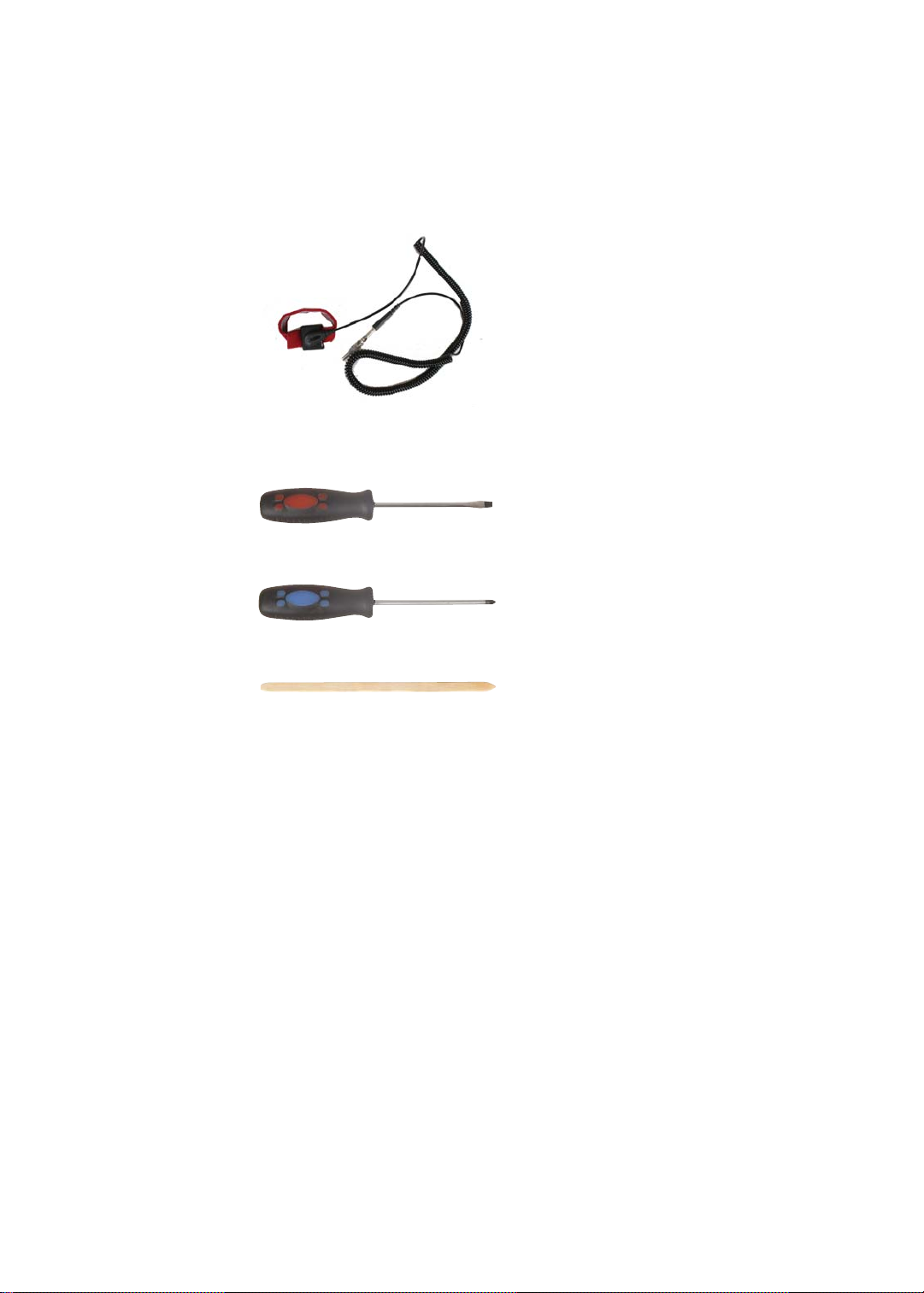
Required tools
To disassemble the notebook, you need the following tools:
• Wrist grounding strap (for ESD prevention)
v
• Flat screwdriver
• Conductive mat (for ESD prevention)
v
• Phillips screwdriver
v
• Non-marring plastic scribe
v
50
www.packardbell.com
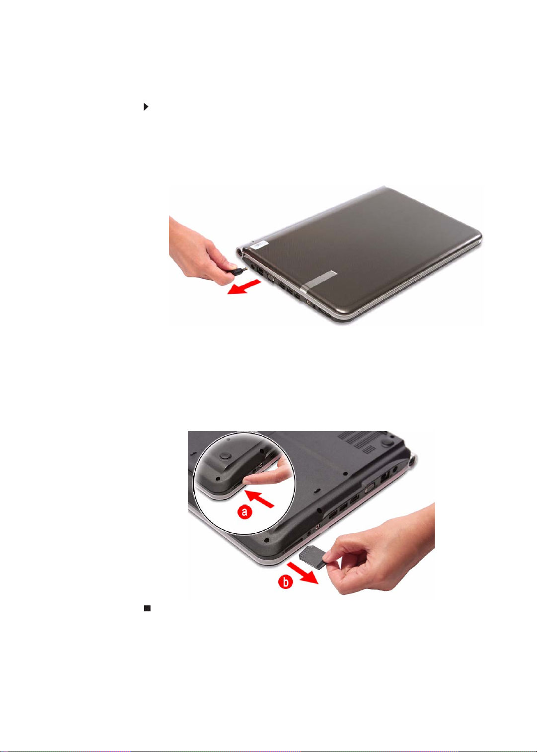
Preparing the notebook
To prepare the notebook for maintenance:
1 Make sure that the optical disc drive is empty.
2 Turn off the notebook.
3 Close the LCD panel.
4 Disconnect the AC adapter.
5 Disconnect the network cable and all peripheral devices connected to the
notebook.
6 Make sure there is no memory card on the card reader slot. To remove a
memory card:
a Push against the card, as if you were pushing it further into the slot,
letting the card spring out
b Pull the memory card out of its slot.
51
CHAPTER 3: Replacing notebook components
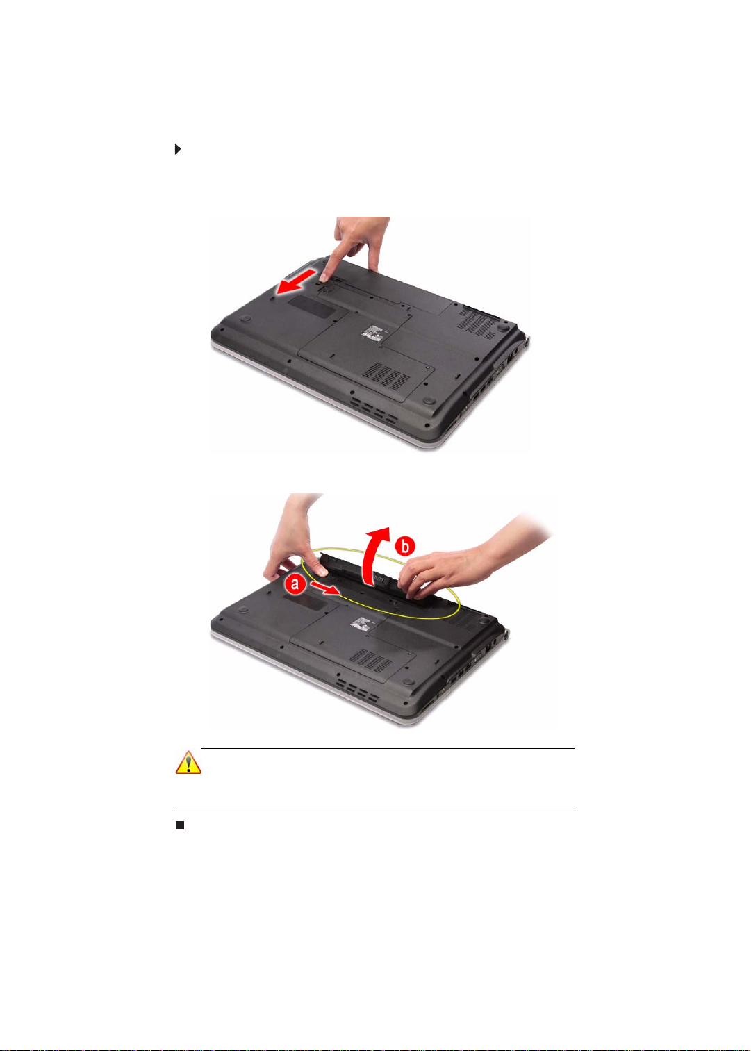
Removing the battery
To remove the battery:
1 Turn the notebook over so the base is facing up.
2 Slide the battery lock to the unlocked position.
3 Slide the battery latch (a), then remove the battery out of the notebook (b).
Note
The battery has been highlighted with a yellow circle in the above
image. Detach the battery and follow local regulations for disposing
it.
52
www.packardbell.com
Phillips #0 screwdriver
Non-marring plastic scribe
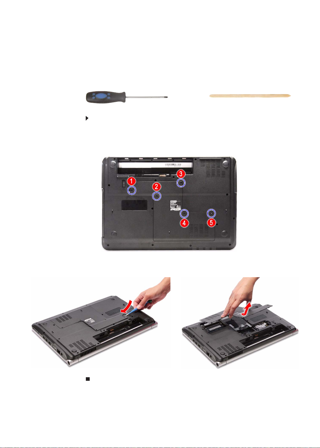
Removing the bay cover
To remove or replace components located on the lower bay, you need to remove
the bay cover first.
Tools you need to complete this task:
To remove the bay cover:
1 Complete the steps in “Preparing the notebook” on page 51.
2 Turn the notebook over so the base is facing up.
3 Loosen the bay cover screws (these screws cannot be removed).
4 Insert a non-marring plastic scribe on the co ver’s notch to relea se the cover
from the computer, and then remove the cover.
53

CHAPTER 3: Replacing notebook components
Phillips #0 screwdriver
Non-marring plastic scribe
Adding or replacing memory modules
Important
Use only memory modules designed for this Packard Bell notebook.
Tools you need to complete this task:
To add or replace memory modules:
1 Complete the steps in “Preparing the notebook” on page 51.
2 Complete the steps in “Removing the bay cover” on page 53.
3 If you are replacing a memory module, go to step 4.
If you installing an additional memory module, go to step 6.
4 Use a non-marring plastic scribe to push out the latches on both sides of
the memory slot until the module tilts upward.
54
5 Remove the memory module from its slot.

www.packardbell.com
6 Insert the new memory module at a 30° angle into an empty memory slot,
and then press it down until it clicks into place.
The module is keyed so it can only be inse rted in one direction. If the module
does not fit, make sure that the notch in the module lines up with the tab in
the memory slot.
7 Reinstall the bay cover.
55
CHAPTER 3: Replacing notebook components
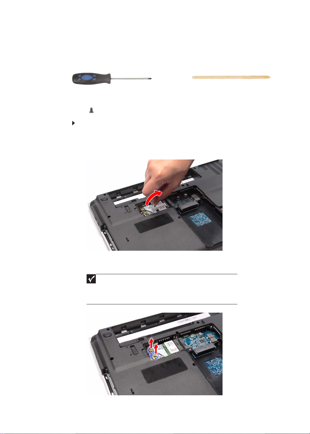
Phillips #0 screwdriver
Non-marring plastic scribe
Replacing the wireless card
Tools you need to complete this task:
Screws removed during this task:
• 1 black M2×5 (wireless card)
To replace the wireless card:
1 Complete the steps in “Preparing the notebook” on page 51.
2 Complete the steps in “Removing the bay cover” on page 53.
3 Detach the bar code sticker covering the antenna cables.
56
4 Unplug the antenna cables. Note which color cable corresponds to each of
the connectors.
Important
The number of antenna cables varies depending on the type
of wireless card installed on the notebook. IEEE 802.11n
cards typically have three antenna cables. Other types of
wireless cards usually have only two antenna cables.
www.packardbell.com
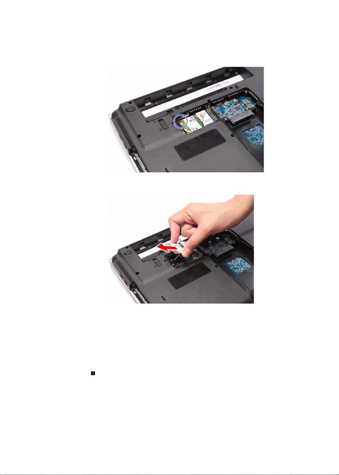
5 Move the antenna cables away from the wireless card screw.
6 Remove the screw securing the wireless card.
7 Pull the card out of the slot.
8 Insert the new wireless card at a 30° angle into the empty Mini Card slot.
The card is keyed so it can only be inserted in one direction. If the card does
not fit, make sure that the notch in the card lines up with the tab in the card
slot.
9 Secure the new wireless card with the screw removed in step 6.
10 Reconnect the antenna cables to the connectors.
11 Reinstall the bay cover.
57
CHAPTER 3: Replacing notebook components
Phillips #0 screwdriver
Non-marring plastic scribe
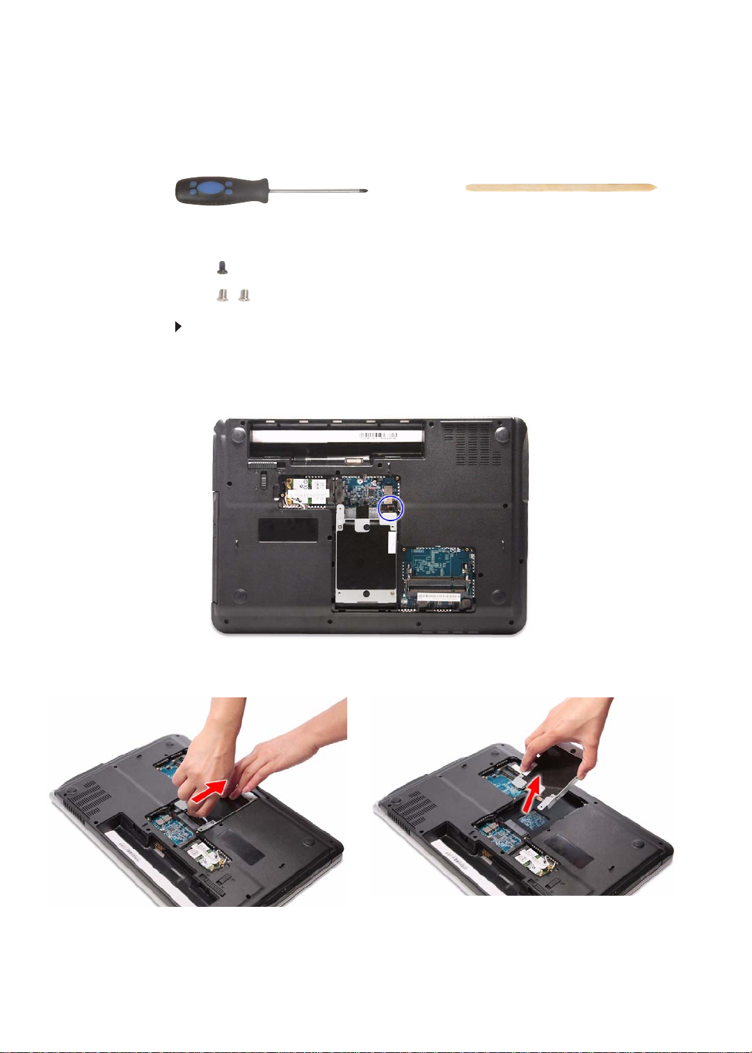
Replacing the hard drive
Tools you need to complete this task:
Screws removed during this task:
• 1 black M2×5 (hard drive)
• 2 chrome M3×3 (hard drive bracket)
To replace the hard drive:
1 Complete the steps in “Preparing the notebook” on page 51.
2 Complete the steps in “Removing the bay cover” on page 53.
3 Remove the hard drive screw.
58
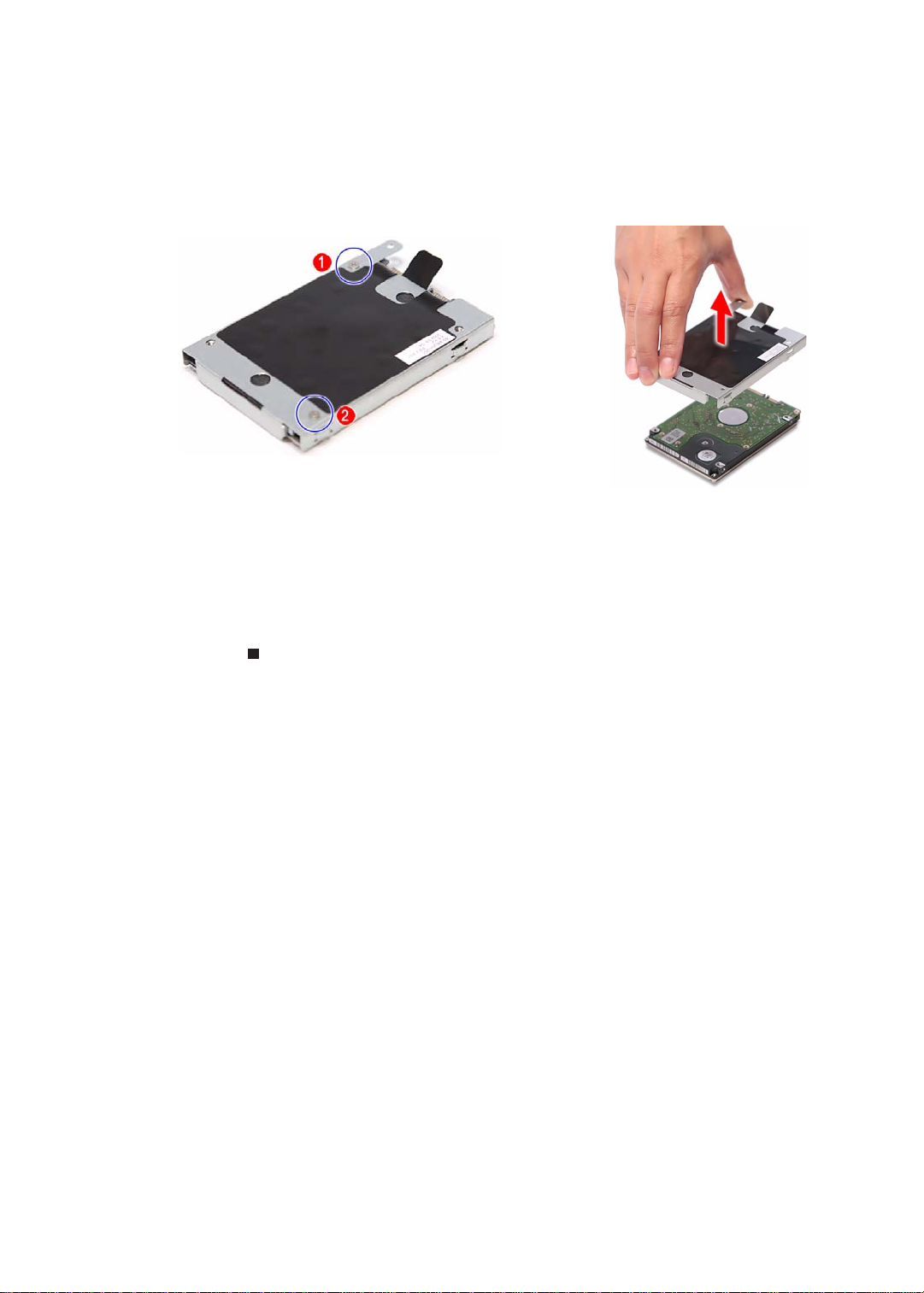
4 Grasp the black mylar tab and use it to disengage the hard drive from its connector,
and then remove the drive from its bay.
www.packardbell.com
5 If your new hard drive already includes the hard drive bracket, go to step 8.
If you need to use the bracket from the old hard drive, go to step 6.
6 Remove the screws that secure the hard drive bracke t, and then det a ch the
bracket from the drive.
7 Place the bracket on the new drive and secure it with the two screws removed
in step 6.
8 Slide the new hard drive into the hard drive bay and make sure it’s properly
engaged to the SATA1 connector.
9 Secure the new drive to the system board with the screw removed in step6.
10 Reinstall the bay cover.
59
CHAPTER 3: Replacing notebook components
Phillips #0 screwdriver
Non-marring plastic scribe
Replacing the optical drive
Tools you need to complete this task:
Screws removed during this task:
• 1 black M2.5×6 (optical drive)
• 1 chrome M2×3 (optical drive bracket)
To replace the optical drive:
1 Complete the steps in “Preparing the notebook” on page 51.
2 Complete the steps in “Removing the bay cover” on page 53.
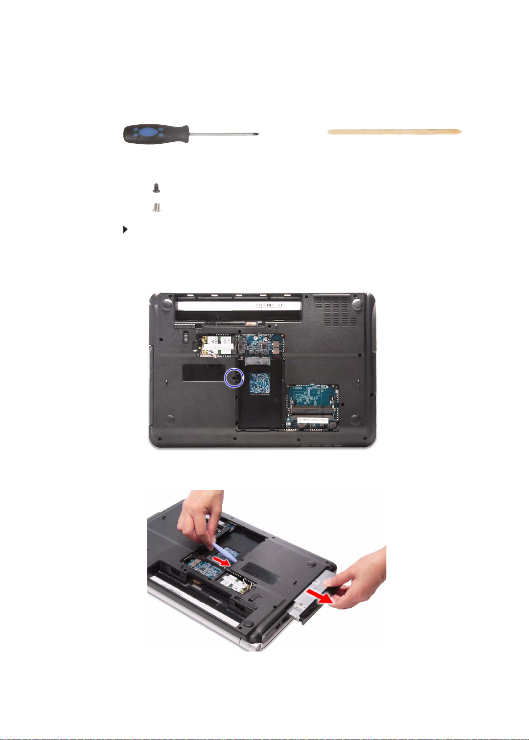
3 Remove the optical drive screw.
60
4 Use the non-marring plastic scribe to carefully push the optical drive out of
the drive bay, and then slide the drive out.
www.packardbell.com
5 If your new optical drive already has it’s own bracket and be zel, go to step 10.
If you need to use the bracket and bezel from the old optical drive, perform
steps 6–9 as necessary.
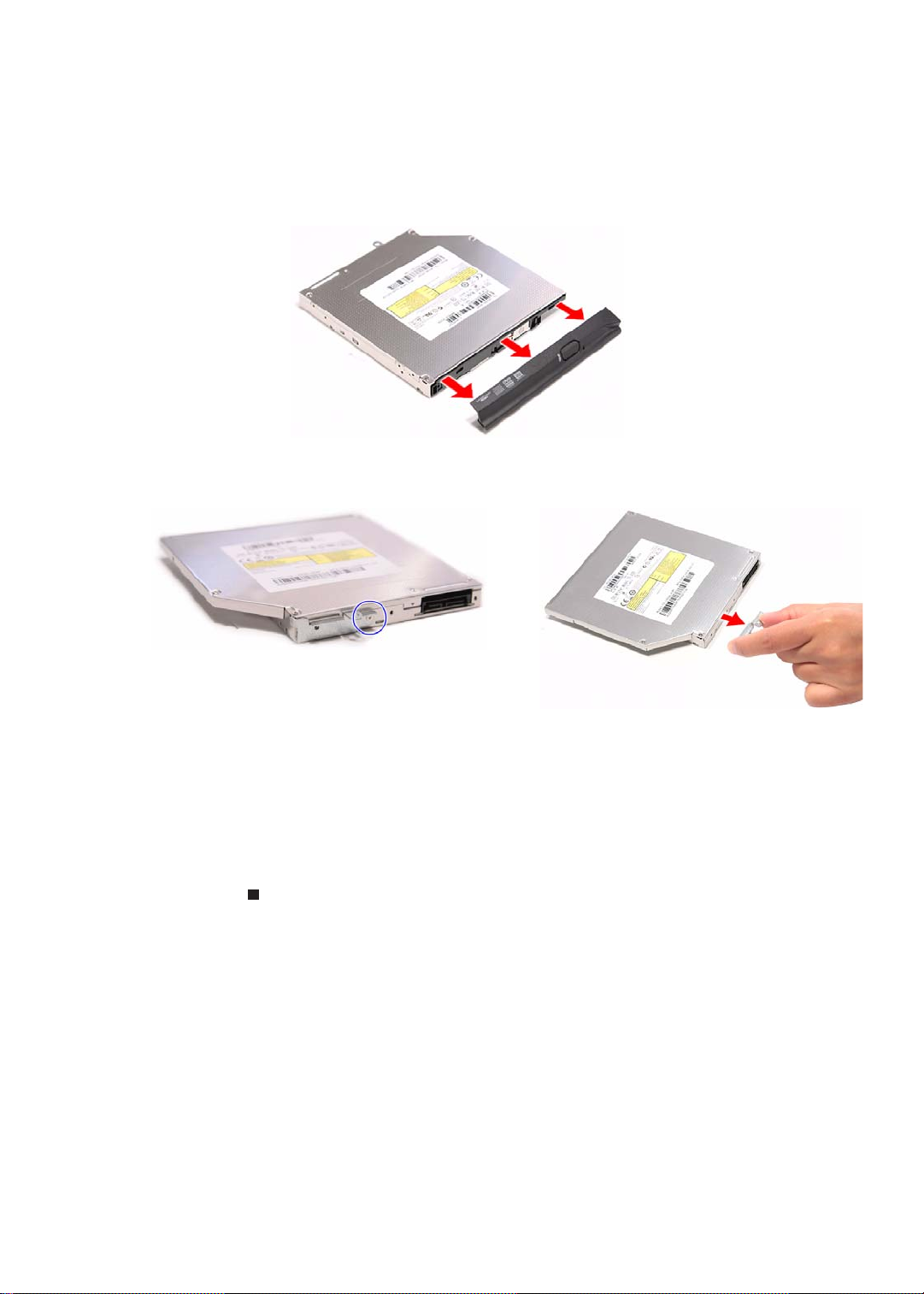
6 Detach the bezel from the old optical drive.
7 Remove the screw that secures the optical drive bracket, and then detach
the bracket from the drive.
8 Attach the bezel to the new optical drive.
9 Attach the bracket to the new optical drive and secure it with the screw
removed in step 7.
10 Slide the new optical drive into the drive bay and make sure it’s properly
engaged to the ODD1 connector.
11 Secure the new drive to the system board with the screw removed in step 3.
12 Reinstall the bay cover.
61
CHAPTER 3: Replacing notebook components
Phillips #0 screwdriver
Flat screwdriver or Non-marring plastic scr ibe
Replacing the keyboard cover
Tools you need to complete this task:
Screws removed during this task:
• 3 black M2.5×6 (keyboard cover)
To replace the keyboard cover:
1 Complete the steps in “Preparing the notebook” on page 51.
2 Complete the steps in “Removing the battery” on page 52.
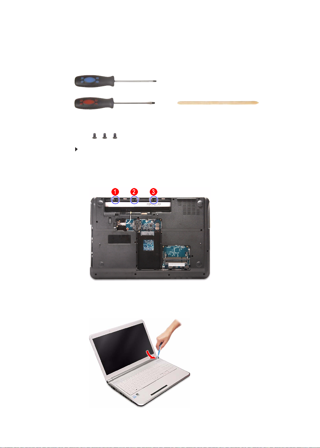
3 Remove the screws securing the keyboard cover.
62
4 Turn the notebook over and o pen the LCD panel to its fully extended position.
5 Insert a small flat-blade screwdriver or non-marring scribe between the LCD
hinge side and the keyboard cover, and carefully pry the cover up.
www.packardbell.com
Caution
The keyboard cover is connected to the notebook through the
multimedia board cable. Disconnect this cable first before pulling the
cover away from the palm rest assembly.
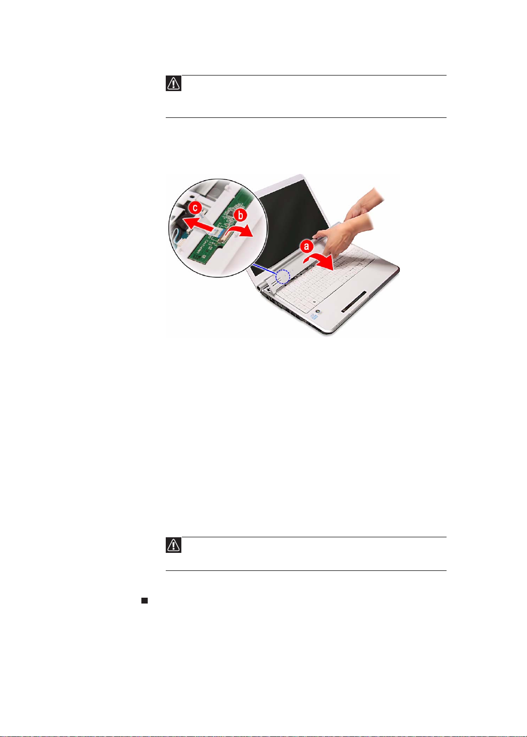
6 Detach the keyboard cover from the palm rest assembly and turn it over the
keyboard to access its underside (a).
Open the multimedia board cable connector (b) and disconnect the cable (c).
7 If you will be using the multimedia board from the old keyboard cover, remove
it by performing steps 3 and 4 of the “Replacing the multimedia board”
procedure on page 64.
8 Secure the multimedia board, with the connector facing up, on the new
keyboard cover.
9 Insert the multimedia cable to its connector on the multimedia board, then
close the clip to lock the cable in place.
10 Insert the tabs on the front side of the keyboard cover into the slots located
on the top corners of the palm rest assembly, then press down on the back
part.
11 Press down on the cover until it clicks in place.
The keyboard cover is correc tly mounte d when you can run yo u finger along
the sides of the cover and find no gaps.
12 Close the LCD panel and turn the notebook over so the base is facing up.
13 Secure the keyboard cover with the screws removed in step 3.
Caution
If the cover is not correctly installed, your notebook could be
damaged when you try to close the LCD panel.
14 Reinstall the battery.
63
CHAPTER 3: Replacing notebook components
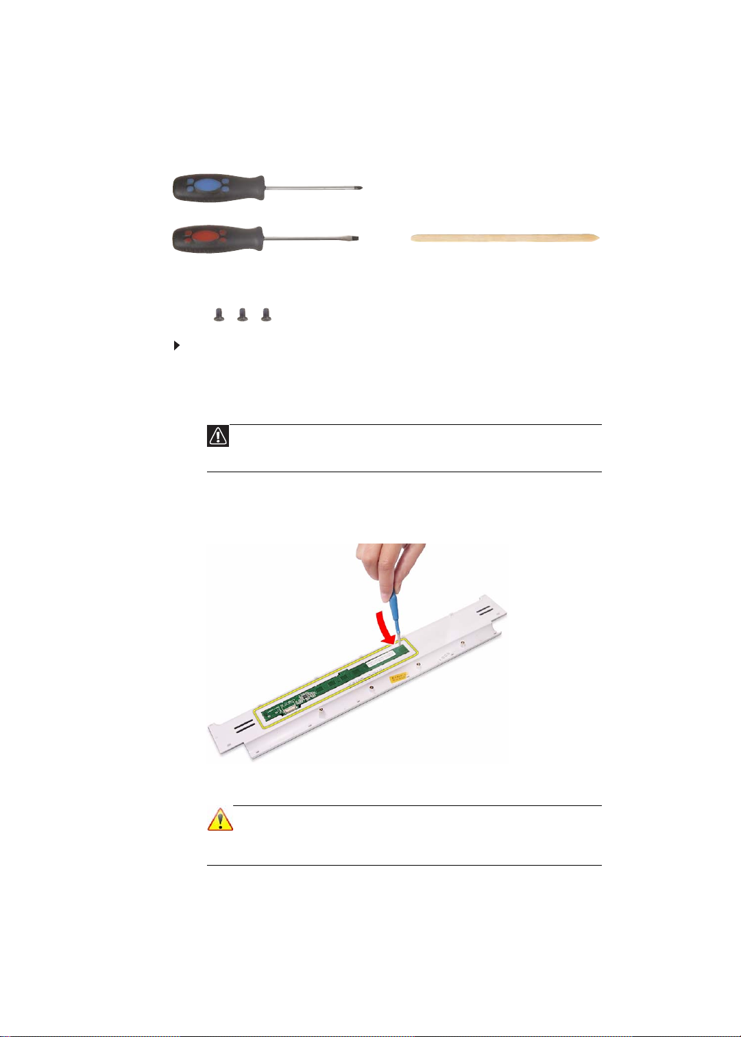
Phillips #0 screwdriver
Flat screwdriver or Non-marring plastic scr ibe
Replacing the multimedia board
Tools you need to complete this task:
Screws removed during this task:
• 3 black M2.5×6 (keyboard cover)
To replace the multim edia board:
1 Complete the steps in “Preparing the notebook” on page 51.
2 Remove the keyboard cover by pe rform ing steps 2–6 of the “Replacing the
keyboard cover” procedure on page 62.
Caution
The multimedia board is glued to the keyboard cover. Remove this
board only if it is defective.
3 Insert a small flat-blade screwdriver or non-marring scribe between the
multimedia board and the keyboard cover’s underside, and carefully pry the
board loose.
4 Remove the multimedia board from the keyboard cover.
Note
A circuit board that is >10 cm2 has been highlighted with a yellow
rectangle as shown in the above image. Follow the local regulations
for disposing this type of circuit board.
64
www.packardbell.com
5 Secure the new multimedia board, with the connector facing up, on the
keyboard cover.
6 Insert the multimedia cable to its connector on the multimedia board, then
close the clip to lock the cable in place.
7 Insert the tabs on the front side of the keyboard cover into the slots located
on the top corners of the palm rest assembly, then press down on the back
part.
8 Press down on the cover until it clicks in place.
The keyboard cover is correc tly mounte d when you can run yo u finger along
the sides of the cover and find no gaps.
9 Close the LCD panel and turn the notebook over so the base is facing up.
10 Secure the keyboard cover with the screws removed in step 3 of the
“Replacing the keyboard cover” procedure on page 62.
Caution
If the cover is not correctly installed, your notebook could be
damaged when you try to close the LCD panel.
11 Reinstall the battery.
65
CHAPTER 3: Replacing notebook components
Phillips #0 screwdriver
Flat screwdriver or Non-marring plastic scr ibe
Replacing the keyboard
Tools you need to complete this task:
Screws removed during this task:
• 3 black M2.5×6 (keyboard cover)
To replace the keyboard:
1 Complete the steps in “Preparing the notebook” on page 51.
2 Remove the keyboard cover by pe rform ing steps 2–6 of the “Replacing the
keyboard cover” procedure on page 62.
Caution
The keyboard is connected to the notebook throu gh the keyboard
cable. Disconnect this cable first before pulling the keyboard away
from the palm rest.
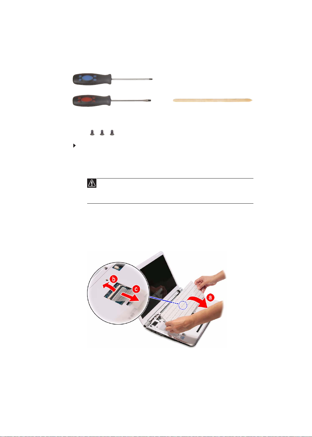
3 Lift the back edge of the keyboard slightly, then carefully slide it toward the
LCD panel to release the keyboard retaining tabs from the palm rest.
4 Flip the keyboard over onto the touchpad area to access to the keyboard
cable (a).
Open the keyboard cable connector (b) and disconnect the cable (c).
66
 Loading...