

Page 1

LCD-550
LOW COST AGILE
TELEVISION DEMODULATOR
INSTRUCTION MANUAL
Phone:
E-Mail: salessupport@olsontech.com
025-000345 REV B 8/21/01
(209) 586-1022
(800) 545-1022
Fax:
(209) 586-1026
www.olsontech.com
Page 2

CAUTION!
USE CARE WHEN CHANGING CHANNELS OR MAKING ADJUSTMENTS TO THE
LCD-550 MODULES
These units are very small and they use smaller (and more delicate) components than are normally found in larger
equipment.
The DIP switch levers can be damaged by excessive force. Use a small pointed object to gently move the switch
levers to the required positions.
The rotating controls can be pushed-in and broken if too much force is applied against them. When adjusting these
controls, use caution and an alignment tool in good condition that is a good fit to the control slot.
025-000345 REV B Page 2
Page 3

INTRODUCTION
The LCD-550 is a small low cost demodulator for use in cable and off-air applications. It is designed to mount
in Olson T echnology’ s LCM-550-RKA rack mountable chassis. The demodulator is shipped as a single LCD-550
and occupies 3 slots in the LCM-550 RKA chassis.
The LCD-550 can be made into a dual demodulator assembly by removing the front panel and guide pin on the
second LCD-550 and installing on top of the first demodulator .
The units have a front panel switch that switches between NTSC broadcast channels and a user defined CA TV
tuning mode. The user can select from 6 NTSC channel plans and frequency tuning.
The units have a single RCA type audio output connector. The type of signal at this connector is selected from
3 types by internal jumpers. The user can choose normal audio, multiplex audio, or subcarrier . RF Input and V ideo
Output connectors are “F” type. See Figure 2 for connector location.
The demods have an LED that indicates low input levels. This LED also flashes with invalid tuning settings.
(LED is labeled “NO VIDEO” on some early models)
INST ALLATION
Units are shipped in the Olson T ech CATV tuning mode with normal audio output. If other settings are
required, go to page 4 for instructions.
Slide the unit into the rack shelf, making sure that the notch on the rear of the unit engages the tab on the shelf.
Install and tighten the front thumb screw .
Connect the Audio and V ideo Output cables and the RF Input cable. Note that the combiner on the rear of
some LCM-550 rack shelves is for outputs, not inputs. It is recommended that units be added with the rack assembly
powered down, but they can be added hot as long as the long ground pin makes contact first. Connect the power
cable(s).
Set the tuning switches to the desired channel. If the unit is driving an LCM-550 with normal audio, no
internal adjustments will be required. See Figure 1 for front panel controls.
025-000345 REV B
Page 3
Page 4
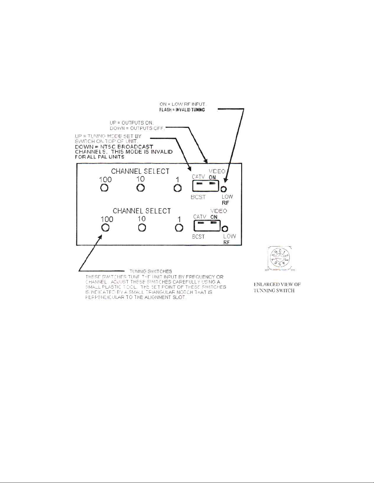
FRONT PANEL CONTROLS
Front panel controls should be adjusted only with plastic alignment tools. Damage may result if metal tools
are used. Refer to the following figure for the location of the front panel controls.
Figure 1
The LOW RF LED turns on with low or missing RF input. It also flashes on invalid tuning or mode settings. All outputs
are squelched with low RF or invalid tuning.
The VIDEO ON dipswitch turns all outputs on and off.
The CA TV -BCST dipswitch changes the tuning mode. In the CA TV position the tuning mode is set by the tuning mode
switch on the top of the demod. The BCST mode tunes NTSC broadcast VHF/UHF channels. This mode is invalid
for all P AL units.
The channel select switches tune the RF input frequency . The set point of these switches is indicated by a small
triangular notch that is perpendicular to the adjustment slot. When tuning by frequency , these switches are the
frequency in MHz, with the .25MHz steps set by the tuning mode switch.
025-000345 REV B
Page 4
Page 5

OPERATION
Most adjustments require removing the top cover . T o access the bottom unit in a dual version, remove the 2
screws holding the top demod to the front panel. T o access the internal adjustments, it is not necessary to remove the
demod from the front panel; just remove the top cover screws. Figure 2 shows the adjustment locations. When all
adjustments are complete, replace the top cover. For dual units, repeat this process for the top unit.
MODE SWITCH
This switch selects the CA TV tuning mode. It is accessed through a hole in the top cover . Note that P AL
units tune by frequency only . Positions 0-2 select traditional channel plans. Positions 3-5 select EIA standard
channel plans. Positions 6-9 select direct frequency tuning.
025-000345 REV B
Page 5
Page 6

INTERNAL CONTROLS
Refer to the following figure for the location of the internal controls
Figure 2
The VID pot sets the video output level. The video level should be measured into a 75ohm load.
The SUB pot sets the subcarrier output level. It does not affect the audio level.
The AUD pot sets the audio output level in both the normal and multiplex modes. It may need adjustment when
changing between normal and multiplex outputs.
The SQL pot sets the low RF level where the outputs are squelched.
There are two jumpers that select the type of audio output. The AUD-SUB jumper selects between subcarrier
and baseband audio outputs. If this jumper is in the AUD position, then the MPX-NOR jumper selects the type of
baseband audio output.
The NOR position is normal audio output. In the MPX position, the audio de-emphasis is disabled. This is
used for multiplex BTSC stereo. In the multiplex mode, the audio pre-emphasis on the associated modulator should
also be disabled
025-000345 REV B
Page 6
Page 7

TROUBLESHOOTING
No output, low RF LED on:
RF input low or absent.
Incorrect tuning mode or channel.
Check the small triangular notch for switch settings.
No output, low RF LED flashes:
Invalid tuning. Check tuning and mode switches. P AL units tune by frequency only. Broadcast
channel mode is also invalid for P AL.
V ideo output very high contrast and distorted:
V ideo output is unterminated.
V ideo output washed out:
V ideo output is double terminated.
Audio problems:
V erify correct jumper settings. Pre-emphasis setting on modulator must
match that of demodulator .
025-000345 REV B
Page 7
Page 8

LCD-550-X1
SPECIFICATIONS
RF Input................................................
RF Input Level.......................................
V ideo Output.........................................
V ideo Performance.................................
Audio Output T ypes...............................
Audio Output.........................................
MPX Audio Output (NTSC)..................
Audio Subcarrier Output........................
NTSC 54 to 801.25MHz
Off-air -10dBmV to +25dBmV
CA TV -10dBmV to +10dBmV
1V p-p +/- 5 IRE into 75Ω
Diff. gain < 5%
Diff. phase < 3°
Normal Audio
Multiplex Audio
Subcarrier
(selected by internal jumpers)
500 mV p-p into 600Ω unbalanced
500 mV p-p into 600Ω unbalanced
> +40dBmV into 75Ω unbalanced
Front Panel Controls..............................
Front Panel Indicator..............................
Rear Panel Connectors...........................
Power Requirements..............................
Size.......................................................
Weight...................................................
Output on/off
CATV/Broadcast
Rotary tuning switches
Low RF
RF in, V ideo out...type “F”
Audio...RCA
< 2 watts from LCM-550 RKA chassis
(5V @ 165mA and 10V @ 30mA typical)
1.3x3x6
< 1 lb.
025-000345 REV B
Page 8
Page 9

CHANNEL PLANS
Frequencies shown are rounded to 2 decimal places. 121.26 indicates a 12.5KHz off-set or 121.2625 assignment.
331.27 is actually 331.2750. The HRC frequencies are based on a harmonic of 6.0003MHz. The LCD-550 has
AFC that will tune to these offsets without any special adjustment.
025-000345 REV B
Page 9
Page 10

025-000345 REV B
Page 10
Page 11

025-000345 REV B
Page 11
Page 12

025-000345 REV B
Page 12
Page 13

025-000345 REV B
Page 13
 Loading...