

Olson Technology HML-C, HMLV-C Installation Manual
Installation, Operation and
Maintenance Manual
Oil Fired Warm Air Furnaces
HML-C (Up-Flow Model)
HMLV-C (Up-Flow Model with ECM)
ALL INSTALLATIONS MUST MEET ALL
LOCAL, PROVINCIAL/STATE, AND
FEDERAL CODES WHICH MAY
DIFFER FROM THIS MANUAL
ECR International Limited
Read this complete manual before
beginning installation. These instructions
must be kept with the furnace for future
reference
30173 Rev B 4/29/2008

TABLE OF CONTENTS
1. INTRODUCTION .................................................................................................................................3
2. HEAT LOSS........................................................................................................................................3
3. LOCATION OF UNIT..........................................................................................................................3
4. AIR CONDITIONING APPLICATIONS ...............................................................................................3
5. COMBUSTION AIR.............................................................................................................................4
6. CHIMNEY VENTING ...........................................................................................................................4
7. BAROMETRIC DAMPER CONTROL.................................................................................................4
8. OPTIONAL SIDE WALL VENTING.....................................................................................................5
9a, 9b. FAN TIMER BOARD AND LIMIT CONTROL (FIGURE 4 AND 5) .............................................5
10. ELECTRICAL CONNECTIONS.........................................................................................................5
11. HUMIDIFIER......................................................................................................................................6
12. PIPING INSTALLATION ...................................................................................................................6
13. OIL FILTER.......................................................................................................................................6
14. OIL BURNER NOZZLES...................................................................................................................6
15. OIL BURNER ADJUSTMENT...........................................................................................................6
16. BURNER ELECTRODES..................................................................................................................6
17. BURNER PRIMARY (SAFETY) CONTROL......................................................................................7
18. COMBUSTION CHAMBER...............................................................................................................7
19a, 19b. CIRCULATING AIR BLOWER................................................................................................7
20. MAINTENANCE AND SERVICE.......................................................................................................7
21. OPERATING INSTRUCTIONS..........................................................................................................8
22. ECM BLOWER MOTOR OPERATION
….………………………………………………………………………..9
APPENDIX A- HML-C AND HMLV-C ....................................................................................................10
A.1 OIL BURNER AIR ADJUSTMENT..................................................................................................11
A.2 BURNER ELECTRODES ................................................................................................................12
A.3 START UP.......................................................................................................................................12
A.4 SPECIAL INSTRUCTIONS FOR UNITS EQUIPPED WITH RIELLO BURNERS...........................12
APPENDIX B: WIRING DIAGRAMS......................................................................................................16
OPERATION OF OIL BURNER.............................................................................................................18
APPENDIX C OIL PRIMARY CONTROL DETAILED SEQUENCE OF OPERATION .........................19
OIL PRIMARY CONTROL LED DIAGNOSTIC LIGHT..........................................................................23
FINAL CHECK OUT...............................................................................................................................29
HOMEOWNER’S REFERENCE TABLE................................................................................................30
PARTS LISTING: HIGHBOY MODEL: HML – 80C AND HMLV-80C ...................................................31
NOTES: ..................................................................................................................................................................34
2
30173 Rev B 4/29/2008
IMPORTANT:
SAVE THESE INSTRUCTIONS FOR FUTURE REFERENCE
1. INTRODUCTION
Please read these instructions completely and carefully
before installing and operating the furnace.
should be centralized with respect to the supply and
return air ductwork. A central location minimizes the
trunk duct sizing. All models may be installed on
combustible floors.
MODELS HML-C AND HMLV-C
Models HML-C and HMLV-C are oil fired forced air upflow furnaces with an output capacity range of 56,000
BTU/Hr. to 95,000 BTU/Hr.
DO NOT USE GASOLINE, CRANK CASE OIL, OR
ANY OIL CONTAINING GASOLINE.
All models are CSA listed, (NRTL/C) for use with No. 1
(Stove) and No. 2 (Furnace) Oil. Please refer to the
tables in Appendix A for performance and dimensional
data.
In Canada, the installation of the furnace and related
equipment shall be installed in accordance with the
regulations of CAN/CSA - B139, Installation Code for Oil-
Burning Equipment, as well as in accordance with local
codes.
In the United States of America, the installation of the
furnace and related equipment shall be installed in
accordance with the regulations of NFPA No. 31,
Standard for the Installation of Oil-Burning Equipment
well as in accordance with local codes.
, as
The minimum installation clearances are listed in
Table 1.
Table 1: Clearances – (Inches)
Clearance to Combustibles
Location
HML-C and HMLV-C
Up flow
Top 1
Bottom 0
S/A Plenum 1
Rear 1
Sides 1
Front 1**
Flue Pipe 9*
Enclosure Closet
*18 in. in USA
** 24 in. required for service clearance
Regulations prescribed in the National Codes and Local
regulations take precedence over the general
instructions provided on this installation manual. When in
doubt, please consult your local authorities.
All models are shipped assembled and pre-wired. The
furnace should be carefully inspected for damage when
being unpacked.
2. HEAT LOSS
The maximum hourly heat loss for each heated space
shall be calculated in accordance with the procedures
described in the manuals of the Heating, Refrigeration
and Air Conditioning Institute of Canada (HRAI), or by
other means prescribed, or approved by the local
authority having jurisdiction.
In the United States, Manual J. titled, "Load Calculation"
published by the Air Conditioning Contractors of
America, describes a suitable procedure for calculating
the maximum hourly heat loss.
3. LOCATION OF UNIT
The furnace should be located such that the flue
connection to the chimney is short, direct and consists of
as few elbows as possible. When possible, the unit
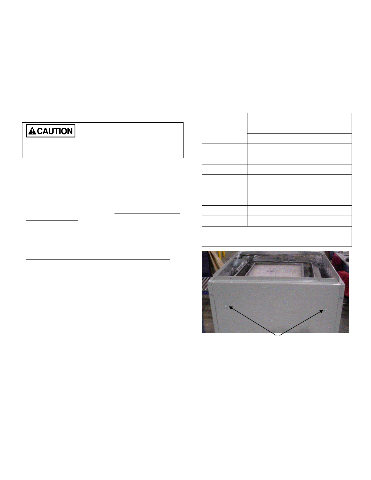
HEAT EXCHANGER SUPPORT SCREWS
Before final placement of the furnace, the heat
exchanger support screws shown in the picture may
be removed. This may be preferable if the furnace
rear panel will be inaccessible after installation. The
screws must be removed if the heat exchanger must
be removed from the cabinet.
4. AIR CONDITIONING APPLICATIONS
If the furnace is used in conjunction with air
conditioning, the furnace shall be installed in parallel
with or upstream from the evaporator coil to avoid
condensation in the heat exchanger. In a parallel
3
30173 Rev B 4/29/2008
 Loading...