


NOKIA 6351, 7151, 7152 LUS2-SN, 6351TN, 7151T Service Manual
...
25
STEREO PLUS 2 |
TV |
SN-CHASSIS |
|
(50 Hz, 4:3) |
11 /1999 |
|
|
G Supplement to service manual |
6611 9613 |
D Ergänzung zum Service-Manual |
6611 9613 |
S Bilaga till serviceanvisning |
6611 9613 |
F Complément du manuel de service |
6611 9613 |
I Supplemento al manuale di servizio |
6611 9613 |
|
|
n |
6351-T |
7151-T Multi |
|
7151-T |
7151-T Multi White |
|
6351-TN |
7152-TN |
|
7151-TN |
7152-TN QUICK |
|
|
|
|
|
|
|
|
|
6611 9656

26
G Contents
Repair instructions ..................................................................................................................................................................... |
1 |
Technical data ............................................................................................................................................................................. |
3 |
SCART connector ....................................................................................................................................................................... |
4 |
Service adjustments................................................................................................................................................................... |
5 |
Schematic diagrams ................................................................................................................................................................ |
10 |
Variable components ............................................................................................................................................................... |
13 |
Spare parts................................................................................................................................................................................ |
15 |
Mechanical parts ...................................................................................................................................................................... |
22 |
D Inhaltsverzeichnis
Reparatur-Anweisung ................................................................................................................................................................ |
1 |
Technische Daten ....................................................................................................................................................................... |
3 |
SCART-Anschluß ........................................................................................................................................................................ |
4 |
Service-Einstellungen ................................................................................................................................................................ |
6 |
Schaltpläne ............................................................................................................................................................................... |
10 |
Röhrenabhängige Bauteile ...................................................................................................................................................... |
13 |
Ersatzteileliste ........................................................................................................................................................................... |
15 |
Mechanische Bauteile .............................................................................................................................................................. |
22 |
S Innehåll
Reparationsinstruktioner |
........................................................................................................................................................... 1 |
Tekniska data .............................................................................................................................................................................. |
3 |
SCART-kontakt ............................................................................................................................................................................ |
4 |
Serviceinställningar ................................................................................................................................................................... |
7 |
Kopplingsschemor ................................................................................................................................................................... |
10 |
Komponentskillnader ............................................................................................................................................................... |
13 |
Reservdelar ............................................................................................................................................................................... |
15 |
Mekaniska delar........................................................................................................................................................................ |
22 |
F Contenu
Instructions de reparation |
......................................................................................................................................................... 2 |
Données techniques................................................................................................................................................................... |
3 |
Connecteur SCART ..................................................................................................................................................................... |
4 |
Réglages de service ................................................................................................................................................................... |
8 |
Schéma ..................................................................................................................................................................................... |
10 |
Composants variables ............................................................................................................................................................. |
13 |
Pièces de rechange .................................................................................................................................................................. |
15 |
Parties mécaniques .................................................................................................................................................................. |
22 |
I Indice
Istruzioni di servizio ................................................................................................................................................................... |
2 |
Dati tecnici .................................................................................................................................................................................. |
3 |
Connettore SCART ..................................................................................................................................................................... |
4 |
Regolazioni di servizio ............................................................................................................................................................... |
9 |
Schema elettrico....................................................................................................................................................................... |
10 |
Componenti che differiscono .................................................................................................................................................. |
13 |
Parti di ricambio ....................................................................................................................................................................... |
15 |
Parti meccaniche ...................................................................................................................................................................... |
22 |
Copyright © 1999 by Semi-Tech (Turku) Oy. All Rights Reserved. www.semitechturku.com

1
G Repair instructions
Service and repair work must be performed only in accordance with the existing safety regulations!
Where a high current or a mechanical stress exists solder connections have been strengthened by using eyelets. Such a connection must not be left without an eyelet.
Wiring has an effect on safety and EMC (ElectroMagnetic Compatibility). Therefore wires must be maintained in their original positions.
X-RAY REGULATIONS:
The picture tube type and the maximum permissible high-voltage ensure that the X-ray intensity of the receiver remains far below the permissible value. The high-voltage must not exceed the value mentioned on the type label. The high voltage is within the permissible limits when the operating voltage (U1) of the horizontal deflection stage is accurate. Refer to the section “Service adjustments”.
ESD Warning
The receiver contains components that are sensitive to electrostatic discharge (ESD). Any servicing or repair work must be done in an environment where the components will not be subjected to ESD. Use a special grounding device!
Surface-Mounted Device (SMD)
SMD´s are glued and soldered. In order not to damage the P.C.B e.g. when replacing ICs and similar components with many soldering points, special tools are required when servicing SMD´s.
Changes
The manufacturer reserves the right to change the design and specification without prior notice.
D Reparatur-Anweisung
Serviceund Reparaturarbeiten dürfen nur in Übereinstimmung mit den gültigen Sicherheitsbestimmungen durchgeführt werden!
Bei bestehendem hohen Stromwerten oder mechanischer Beanspruchung müssen Lötverbindungen durch Ösen verstärkt werden. Eine derartige Verbindung darf nicht ohne Öse ausgeführt werden.
Die Verdrahtung hat Einfluß auf die Sicherheit und die elektromagnetische Verträglichkeit. Daher muß die ursprüngliche Anordnung der Verdrahtung erhalten bleiben.
RÖNTGENVERORDNUNG
Der Bildröhrentyp und die maximal zulässige Hochspannung stellen sicher, daß die Intensität der Röntgenstrahlen des Fernsehgerätes weit unter dem zulässigen Wert bleibt. Die Hochspannung darf nicht den auf dem Typenschild befindlichen Wert überschreiten. Die Hochspannung liegt im zulässigen Bereich, wenn die Betriebsspannung (U1) der Horizontal-Ablenkstufe genau eingehalten wird. Siehe auch Abschnitt “Service-Einstellungen“.
EGB-Warnung
Das Fernsehgerät enthält Bauteile, die empfindlich auf elektrostatische Entladung reagieren. Alle Serviceoder Reparaturarbeiten sind in einer Umgebung durchzuführen, in der die Bauteile nicht elektrostatischer Entladung ausgesetzt sind. Verwenden Sie eine spezielle Erdungsvorrichtung!
SMD-Bauelement
Die SMD’s sind geklebt und verlötet. Es sind spezielle Werkzeuge erforderlich, damit bei Austausch von ICs und ähnlichen Bauteilen mit vielen Lötpunkten die Leiterplatte nicht beschädigt wird.
Änderungen
Der Hersteller behält sich das Recht vor, Änderungen in Bauart und Ausführung ohne vorherige Ankündigung durchzuführen.
S Reparationsinstruktioner
Service och reparationer måste utföras med hänsyn till gällande säkerhetföreskrifter.
Lödningar som utsätts för höga strömmar eller mekanisk belastning är förstärkta med genomföringshylsor. Dessa anslutningar får inte lämnas utan dessa hylsor.
Kabeldragningen har inverkan på säkerhet och EMC (Elektromagnetisk kompabilitet). Därför måste kablarna monteras i deras originalposition.
RÖNTGENSTRÅLNING:
Bildrörstyp och begränsning av maximum högspänning garanterar att mottagarens röntgenstrålning hålls långt under tillåten nivå. Högspänningen får inte överskrida värdet som visas på typetiketten. Högspänningen är inom tillåtna gränser när horisontalavlänkningens drivspänning (U1) är rätt inställd. Se avsnitt “Serviceinställningar”.
ESD varning
Mottagaren har komponenter som är känsliga för elektrostatisk urladdning (ESD). All servicearbete måste göras så att dessa komponenter inte utsätts för ESD. Använd en speciell jordninganordning.
Ytmonterade komponenter (SMD)
SMD-komponenterna är både limmade och fastlödda. För att inte skada kretskortet när man t.ex. byter IC:n med många lödpunkter bör man använda specialverktyg.
Ändringar
Tillverkaren reserverar rätt till att ändra design och spesifikationer utan skild meddelande.

2
F Instructions de reparation
Les opérations de maintenance et les réparations ne doivent être effectuées qu’en conformité avec les règles de sécurité en vigueur !
Les connexions par soudure doivent être renforcées par des oeillets lorsqu’elles sont soumises à une forte intensité de courant ou à des contraintes mécaniques importantes. Ces connexions doivent toujours être renforcées par ce moyen.
Le câblage est un facteur important pour la sécurité et les perturbations électromagnétiques. En conséquence, maintenez les câbles dans leur position initiale.
REGLEMENTATION RELATIVE AUX RAYONS X :
Votre tube cathodique et la tension maximale autorisée garantissent le maintien des rayons X bien en decà du niveau autorisé. La tension la plus élevée ne doit pas dépasser la valeur indiquée sur la plaquette signalétique de l’appareil. Cette tension reste dans la fourchette autorisée lorsque la tension de service (U1) d’étage de déflexion horizontale est précise. Reportezvous à la section “Réglages de service”.
Avertissement concernant les décharges électrostatiques
Le récepteur contient des composants sensibles aux décharges électrostatiques (DES). Les opérations de maintenance et les réparations doivent être effectuées dans un environnement n’exposant pas les composants à ces décharges. Pour cela, utilisez un dispositif de mise à la terre spécial !
Composants montés en surface (SMD)
Ces composants sont collés et soudés. Pour ne pas endommager les cartes à circuits imprimés, par exemple lors du remplacement de circuits et de composants similaires ayant de nombreux points de soudure, vous devez utiliser des outils spécifiques lorsque vous effectuez la maintenance des appareils montés en surface.
Modifications
Le fabricant se réserve le droit de modifier la conception et les caractéristiques de son produit sans avis préalable.
I Istruzioni di servizio
Interventi di assistenza tecnica e riparazione devono essere eseguiti nel più assoluto rispetto delle norme di sicurezza vigenti!
Qualora esistano condizioni di elevati livelli di corrente e stress meccanici le connessioni saldate sono state potenziate tramite occhielli. Questo tipo di connessioni non devono essere lasciate senza occhiello.
Le connessioni influiscono sulla sicurezza e gli standard EMC (Electro-Magnetic Compatibility). Pertanto, i fili elettrici devono essere mantenuti nelle loro posizioni originarie.
NORME SUI RAGGI X:
Il tipo di tubo catodico unitamente all’uso del massimo livello di alta tensione consentito fanno sì che l’intensità dei raggi X del ricevitore rimanga molto al di sotto del valore consentito. L’alta tensione non deve superare il valore indicato sull’apposita etichetta. L’alta tensione rientra nei limiti consentiti quando la tensione operativa (U1) del livello di deflessione orizzontale è corretta. Fare riferimento alla sezione “Regolazioni di servizio”.
Avvertenza ESD (scariche elettrostatiche)
Il ricevitore contiene componenti sensibili all’elettricità statica. Qualsiasi intervento di assistenza tecnica o riparazione deve essere eseguito in un ambiente in cui i componenti non possano essere soggetti a scariche elettrostatiche (ESD). A tal fine, usare uno specifico dispositivo di messa a terra!
Dispositivi SMD (Surface-Mounted Device)
I dispositivi SMD sono incollati e saldati. Sono necessari strumenti specifici per non danneggiare la scheda PCB quando si sostituiscono circuiti integrati (IC) e simili componenti con molti punti di saldatura.
Modifiche
La Casa costruttrice si riserva il diritto di modificare il design e le specifiche senza preavviso.

Technical data |
Technische Daten |
Tekniska data |
Données téchniques |
Dati tecnici |
|
|
|
|
|||||
System |
Norm |
Norm |
Systéme |
Sistema |
|
PAL/SECAM B, G, NTSC 4.43 |
|||||||
Multinorm 2) |
Multinorm 2) |
Multinorm-TV 2) |
Téléviseurs multinormes 2) |
Televisori multistandard 2) |
|
PAL/SECAM,NTSC 4.43, B, G, D, |
|||||||
NTSC |
NTSC |
NTSC |
NTSC |
NTSC |
|
K, K1, L, L’, I |
|
|
|||||
|
3.582) / 4.43 MHz via Scart conn. |
||||||||||||
Mains power |
Netzanschluß |
Nätanslutning |
Alimentation |
Tensione di alimentazione |
|
210...240 V, 50 Hz |
|
|
|||||
Consumption 1) |
|
|
|
||||||||||
Leistungsaufnahme 1) |
Effektförbrukning 1) |
Consommation 1) |
Consumo energetico 1) |
|
90 W (normal) |
|
|
||||||
In stand-by |
Im Bereitschaft |
I beredskapsläget |
En mode veille |
In standby |
|
Max 4.5 W |
|
|
|||||
Frequency range |
Frequenzbereich |
Frekvensområde |
Gamme de fréquences |
Campo di frequenza |
|
48.25...863.25 MHz |
|
|
|||||
|
|
|
|
|
|||||||||
Sound output (RMS) |
Tonendstufe (RMS) |
Ljudeffekt (RMS) |
Sortie sonore (RMS) |
Potenza audio (RMS) |
|
2 x 6 W/8 Ω |
|
|
|||||
Connections on the front panel |
Anschlüsse an der Vorderseite |
Anslutningar på framsidan |
Connexions sur le panneau |
Connessioni sul pannello |
|
|
|
|
|||||
Headphones |
|
|
|
|
avant |
frontale |
|
16...600 Ω, 3.5 mm |
|
|
|||
Kopfhöreranschluß |
Hörlurar |
Ecouteurs |
Cuffia |
|
|
|
|||||||
Audio/Video |
Audio/Video |
Audio/Video |
Audio/Vidéo |
Audio/Video |
|
Audio in: 0...2 V/10 kΩ (RMS)2) |
|||||||
|
|
|
|
|
|
|
|
|
|
|
Video in: 1 V/75 Ω2) |
|
|
|
|
|
|
|
|
|
|
|
|
|
Y/C in (SVHS/Hi8)2) |
|
|
Connections on the rear panel |
Anschlüsse an der Rückseite |
Anslutningar på baksidan |
Connexions sur le panneau |
Connessioni sul pannello |
|
|
|
|
|||||
Audio/Video |
|
|
|
|
arrière |
posteriore |
|
Audio in: 0...2 V/10 kΩ (RMS) |
|||||
Audio/Video |
Audio/Video |
Audio/Vidéo |
Audio/Video |
|
|||||||||
|
|
|
|
|
|
|
|
|
|
|
Audio out: 0...2 V/1kΩ (RMS) |
||
|
|
|
|
|
|
|
|
|
|
|
Video in/out: 1 V/75 Ω |
|
|
|
|
|
|
|
|
|
|
|
|
|
RGB in: 0.7 V/75 Ω (E1) |
|
|
|
|
|
|
|
|
|
|
|
|
|
Y/C in (SVHS/Hi8) (E1, E22)) |
||
Audio output |
Audio Ausgang |
Ljudutgångar |
Sortie audio |
Uscita audio |
|
0...1.5 V/1 kΩ (RCA)2) |
|
|
|||||
External loudspeakers |
Externe Lautsprecher |
Extrahögtalare |
Haut-parleurs externes |
Altoparlanti esterni |
|
min 10 W/8 Ω (RMS) |
|
|
|||||
Antenna |
Antennenanschluß |
Antenn |
Antenne |
Antenna |
|
75 Ω |
|
|
|||||
Programme memory |
Vorwählbare Speicherplätze |
Antal programplatser |
Emplacements mémoire des |
Posizioni memoria canali |
|
99 |
|
|
|||||
locations |
|
|
|
||||||||||
|
|
|
|
programmes |
|
|
|
|
|
|
|||
|
|
|
|
|
|
|
|
|
|
|
|
||
AV memory locations |
AVSpeicherplätze |
Antal AV-programplatser |
Emplacements mémoire AV |
Posizioni memoria AV |
|
1-3 |
|
|
|||||
(according to the model) |
|
|
|
||||||||||
(Abhängig von Modell) |
(beroende på modell) |
(dépend de modéle) |
(a seconda il modello) |
|
|
|
|
||||||
|
|
|
|
|
|
||||||||
Dimensions |
Maße |
Mått |
Mesurer |
Dimensioni |
|
|
|
|
|||||
(Width x depth x height / weight) |
|
|
|
|
|||||||||
(Weite x Tiefe x Höhe / Gewicht) |
(Bredd x djup x höjd / vikt) |
(Largeur x profondeur x hauteur / poids) |
(Larghezza x profondita x altezza |
/ peso) |
|
|
|
||||||
25” L1 |
25” L1 |
25” L1 |
25” L1 |
25” L1 |
|
700 x 486 x 511 mm |
/ |
28,5 kg |
|||||
28” L1 |
28” L1 |
28” L1 |
28” L1 |
28” L1 |
|
780 x 510 x 564 mm |
/ |
34,5 kg |
|||||
28” Q1 |
28” Q1 |
28” Q1 |
28” Q1 |
28” Q1 |
|
767 x 490 x 546 mm |
/ |
31,5 kg |
|||||
Specifications are subject to |
Änderungen vorbehalten |
Rätt till ändringar förbehålles. |
Les spécifications peuvent être |
Le specifiche sono soggette a |
|
|
|
||||||
change. |
|
|
|
|
modifiées sans préavis. |
cambiamenti. |
|
|
|
|
|||
1) |
Depends on option modules |
1) |
Abhängig von |
1) |
Varierar beroende på modul- |
1) |
Dépend des modules option- |
1) |
A seconda dei moduli opzione |
|
|
|
|
|
and picture tube. |
|
Optionsmodulen und |
|
uppsättning och bildrör. |
|
nels et du tube cathodique. |
|
e del tubo catodico. |
|
|
|
|
2) |
Not in all models. |
|
Bildröhre. |
2) |
Inte i alla modeller. |
2) |
Pas sur tous les modèles. |
|
|
|
|
|
|
2) |
Nicht in allen Modellen. |
2) |
Non in tutti i modelli. |
|
|
|
|
||||||
|
|
|
|
|
|
|
|
|
|
|
|
|
|
3
4
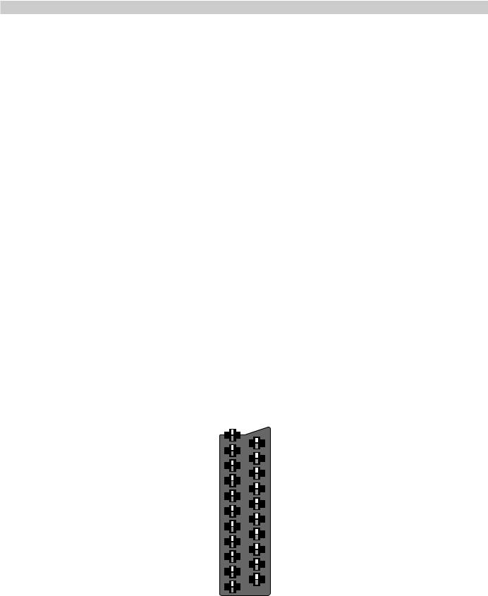
SCART connector
Pin |
SCART 1 |
SCART 2 |
1 |
Audio out R |
Audio out R |
2 |
Audio in R |
Audio in R |
3 |
Audio out L |
Audio out L |
4 |
Audio ground |
Audio ground |
5 |
RGB ground, blue |
Ground |
6 |
Audio in L |
Audio in L |
|
|
|
7 |
RGB input, blue |
S-video out (chrominance) |
|
|
(copy from front AV-connector) |
8 |
Switching voltage |
Switching voltage |
|
0...2 V : no function |
0...2 V : no function |
|
4.5...7 V : 16/9 picture ratio |
4.5...7 V : 16/9 picture ratio |
|
9.5...12 V : normal picture ratio |
9.5...12 V : normal picture ratio |
|
|
|
9 |
RGB ground, green |
Ground |
|
|
|
10 |
- |
- |
11 |
RGB input, green |
- |
12 |
- |
- |
13 |
RGB ground, red |
S-video ground (chrominance) |
14 |
Ground |
Ground |
15 |
RGB input, red |
S-video input (chrominance) |
|
(or S-video chrominance input if scart 1 only) |
|
16 |
Switching voltage, RGB blanking |
- |
17 |
Ground, video in |
Ground, video in |
18 |
Ground, video out |
Ground, video out |
|
|
|
19 |
Video out |
Video out |
|
S-video out (luminance) |
|
20 |
Video in |
Video in |
|
RGB sync in |
S-video in (luminance) |
|
|
|
21 |
Shield |
Shield |
|
|
|
21
19
20
17
18
15
16
13
14
11
12
9
10
7
8
5
6
3
4
1
2
5
Service adjustments
Configuration and fault diagnosis
The set must be configured after adding or removing any option. By pressing the RED button in service mode, the processor checks the configuration of the TV set and shows the settings on the screen. The configuration can be stored by pressing the OK button.
This feature can also be used in fault diagnosis. If an option bit is not ’1’ when it should be, the IC (or feature) is either not present or faulty.
Note! IIC DEV 1, IIC DEV 2, AUTO OPT and IF OPT bytes are configured automatically every time the RED-button is pressed.
TEXT OPT, HW OPT and SW OPT bytes must be set manually.
Changing the option bytes
1.Select the configuration mode by pressing the RED button in the service mode.
 Service
|
|
Bit |
0: |
|
|
|
|
TV tuner |
|
||
|
± |
|
|
|
|
|
|
IIC |
DEV 1 |
00001111 |
|
|
|
||||
|
|
IIC |
DEV 2 |
00000000 |
|
Auto |
|
|
|
|
|
|
|
|
|
|
|
|
|
AUTO OPT |
10010001 |
||
|
|
IF OPT |
00000001 |
||
|
|
||||
Manual |
|
TEXT OPT |
00000011 |
||
|
|||||
|
HW |
OPT |
00000000 |
||
|
|
SW |
OPT |
00000010 |
|
|
|
– |
|
|
|
|
|
|
|
|
|
|
|
SW VER |
SP2Axx.x |
||
|
|
NVM |
VER |
|
SP21-xx |
SW VER = µP software version.
NVM VER = NVRAM software version.
2.Select IIC Device byte 1 - 2 or Option byte 1 - 5 with cursor buttons (up/down). The selected byte is shown highlighted.
The name of a responding bit can be seen by using cursor buttons (left/right).
3.Set / clear the bits with number buttons (0 ... 7).
4.Store the settings by pressing the OK button.
5.Return to the normal service mode by pressing the RED button.
Option byte description |
|
|
|
|
|
|
|
|
|
|
|||
Bit |
Description |
|
|
|
Setting |
’1’ |
`0’ |
||||||
|
|
|
7 |
6 |
5 |
4 |
3 |
2 |
1 |
0 |
|
|
|
|
IIC DEV 1 |
|
00001111 |
|
|
|
|||||||
0 |
TV tuner 5002PH5 |
|
|
|
|
|
|
|
|
|
Yes |
No |
|
1 |
Decoder/sync processor TDA8854 |
Yes |
No |
||||||||||
2 |
Teletext processor TPU3050 |
|
|
|
|
|
Yes |
No |
|||||
3 |
Sound processor MSP34x0 |
|
|
|
|
|
Yes |
No |
|||||
4 |
Video matrix switch TEA6415 |
|
|
|
|
Yes |
No |
||||||
5 |
PIP processor |
|
|
|
|
|
|
|
|
|
Yes |
No |
|
6 |
PIP tuner |
|
|
|
|
|
|
|
|
|
Yes |
No |
|
7 |
3D virtual sound processor |
|
|
|
|
|
Yes |
No |
|||||
|
|
|
|
|
|
|
|||||||
|
IIC DEV 2 |
|
00000000 |
|
|
|
|||||||
5 |
Power controller STV5180 |
|
|
|
|
|
|
Yes |
No |
||||
6 |
Sound processor MSP3410 |
|
|
|
|
|
Yes |
No |
|||||
7 |
Reserved for production use |
|
|
|
|
Yes |
No |
||||||
|
|
|
|
|
|
|
|||||||
|
AUTO OPT |
|
10010001 |
|
|
|
|||||||
0 |
Scart 2 |
|
|
|
|
|
|
|
|
|
Yes |
No |
|
1 |
16:9 picture tube |
|
|
|
|
|
|
|
|
|
Yes |
No |
|
3 |
Text memory 4 Mb DRAM |
|
|
|
|
|
|
Yes |
No |
||||
4 |
Text memory 1 Mb SRAM |
|
|
|
|
|
|
Yes |
No |
||||
5 |
Text memory 256 kb SRAM |
|
|
|
|
|
Yes |
No |
|||||
6 |
Tilt adjustment |
|
|
|
|
|
|
|
|
|
Yes |
No |
|
7 |
NICAM identification enabled |
|
|
|
|
Yes |
No |
||||||
|
|
|
|
|
|
|
|||||||
|
IF OPT |
|
00000001 |
|
|
|
|||||||
0 |
B/G system in IF |
|
|
|
|
|
|
|
|
|
Yes |
No |
|
1 |
I system in IF |
|
|
|
|
|
|
|
|
|
Yes |
No |
|
2 |
D/K system in IF |
|
|
|
|
|
|
|
|
|
Yes |
No |
|
3, 4 |
L/L' system in IF |
|
|
|
|
|
|
|
|
|
Yes |
No |
|
5 |
HEF4094B in IF |
|
|
|
|
|
|
|
|
|
Yes |
No |
|
|
|
|
|
|
|
|
|||||||
|
TEXT OPT |
|
00000011 |
|
|
|
|||||||
1 |
FLOF function enabled |
|
|
|
|
|
|
|
|
Yes |
No |
||
7,6,5 |
Text character set selected |
|
|
|
|
|
|
|
|
||||
|
000 = West Europe / Czech |
|
|
|
|
|
|
|
|
||||
|
001 = East Europe |
|
|
|
|
|
|
|
|
|
|
|
|
|
010 = West Europe / USA |
|
|
|
|
|
|
|
|
||||
|
011 = West Europe / Turkish |
|
|
|
|
|
|
|
|||||
|
100 = East Europe 2 |
|
|
|
|
|
|
|
|
|
|
|
|
|
|
|
|
|
|
|
|||||||
|
HW OPT |
|
00000000 |
|
|
|
|||||||
0 |
A/V connector installed |
|
|
|
|
|
|
|
|
Yes |
No |
||
1 |
SVHS input in AV |
|
|
|
|
|
|
|
|
|
Yes |
No |
|
2 |
3.58 MHz xtal installed |
|
|
|
|
|
|
|
|
Yes |
No |
||
3 |
Line-out installed |
|
|
|
|
|
|
|
|
|
Yes |
No |
|
|
|
|
|
|
|
|
|||||||
|
SW OPT |
|
00000010 |
|
|
|
|||||||
1 |
Carrier mute enabled |
|
|
|
|
|
|
|
|
|
Yes |
No |
|
2 |
Stand-by prevent |
|
|
|
|
|
|
|
|
|
Yes |
No |
|
3 |
Autostart enabled (Special use only!) |
Yes |
No |
||||||||||
4 |
Pal + helper blanking 4:3 |
|
|
|
|
|
|
|
Yes |
No |
|||
5 |
E1 FB enabled (USER) |
|
|
|
|
|
|
|
|
Yes |
No |
||
7 |
Hotel TV enabled |
|
|
|
|
|
|
|
|
|
Yes |
No |
|
|
|
|
|
|
|
|
|||||||
|
SW VER |
|
SP2Axx.x |
|
|
|
|||||||
|
SW VER = µP software version |
|
|
|
|
|
|||||||
|
|
|
|
|
|||||||||
|
NVM VER |
|
SP21-xx |
|
|
|
|||||||
|
NVM VER = NVRAM software version |
|
|
||||||||||
6
Service-Einstellungen
Konfiguration und Fehlerdiagnose
Das Fernsehgerät muß nach Hinzufügen oder Wegnahme jeder Option konfiguriert werden. Bei Drücken der roten Taste im Servicemodus überprüft der Prozessor die Konfiguration des Fernsehgerätes und zeigt die Einstellungen auf dem Bildschirm. Die Konfiguration kann durch Drücken der OK-Taste gespeichert werden.
Dieses Feature kann auch bei der Fehlerdiagnose verwendet werden. Wenn ein Optionsbit nicht wie vorgesehen ‘1’ ist, ist der IC (oder das Feature) entweder nicht vorhanden oder fehlerhaft.
Hinweis! IIC DEV 1, IIC DEV 2, AUTO OPT und die IF OPT-Bytes werden immer bei Drücken der roten Taste konfiguriert.
TEXT OPT, HW OPT und die SW OPT-Bytes müssen manuell eingestellt werden.
Ändern der Optionsbytes
1.Wählen Sie den Konfigurationsmodus durch Drücken der roten Taste im Servicemodus.
 Service
|
|
Bit |
0: |
|
|
|
|
TV tuner |
|
||
|
± |
|
|
|
|
|
|
IIC DEV 1 |
00001111 |
||
|
|
||||
|
|
IIC DEV 2 |
00000000 |
||
Auto |
|
|
|
|
|
|
|
|
|
|
|
|
|
AUTO OPT |
10010001 |
||
|
|
IF OPT |
00000001 |
||
|
|
||||
Manuell |
|
TEXT OPT |
00000011 |
||
|
|||||
|
HW |
OPT |
00000000 |
||
|
|
SW |
OPT |
00000010 |
|
|
|
– |
|
|
|
|
|
|
|
|
|
|
|
SW VER |
SP2Axx.x |
||
|
|
NVM VER |
|
SP21-xx |
|
SW VER = µP Softwareversion.
NVM VER = NVRAM Softwareversion.
1.Wählen Sie das IIC Device-Byte 1 - 2 oder das OptionByte 1 - 5 mit den Cursortasten (auf-/abwärts). Das gewählte Byte erscheint hervorgehoben.
Der Name eines zugehörigen Bytes wird bei Benutzung der Cursortasten (links/rechts) sichtbar.
3.Die Einstellung bzw. das Löschen der Bits erfolgt mit den Zifferntasten (0 ... 7).
4.Speichern Sie die Einstellungen durch Drücken der OK-Taste.
5.Gehen Sie durch Drücken der roten Taste in den normalen Servicemodus zurück.
Beschreibungen der Options-Bytes |
|
||||||||||
Bit |
Beschreibung |
|
Einstellung |
’1’ `0’ |
|||||||
|
|
7 |
6 |
5 |
4 |
3 |
2 |
1 |
0 |
|
|
|
IIC DEV 1 |
00001111 |
|
|
|||||||
0 |
TV-Tuner 5002PH5 |
|
|
|
|
|
|
|
|
|
Ja Nein |
1 |
Decoder/Synchronprozessor TDA8854 |
Ja Nein |
|||||||||
2 |
Videotextprozessor TPU3050 |
|
|
|
|
Ja Nein |
|||||
3 |
Tonprozessor MSP34x0 |
|
|
|
|
|
|
|
Ja Nein |
||
4 |
Videomatrixschalter TEA6415 |
|
|
|
|
Ja Nein |
|||||
5 |
PIP-Prozessor |
|
|
|
|
|
|
|
|
|
Ja Nein |
6 |
PIP-Tuner |
|
|
|
|
|
|
|
|
|
Ja Nein |
7 |
3D Virtueller Tonprozessor |
|
|
|
|
|
|
Ja Nein |
|||
|
|
|
|
|
|||||||
|
IIC DEV 2 |
00000000 |
|
|
|||||||
5 |
Spannungsregler STV5180 |
|
|
|
|
|
Ja Nein |
||||
6 |
Tonprozessor MSP3410 |
|
|
|
|
|
|
|
Ja Nein |
||
7 |
Für die Produktion reserviert |
|
|
|
|
Ja Nein |
|||||
|
|
|
|
|
|||||||
|
AUTO OPT |
10010001 |
|
|
|||||||
0 |
Scart 2 |
|
|
|
|
|
|
|
|
|
Ja Nein |
1 |
Bildröhre 16:9 |
|
|
|
|
|
|
|
|
|
Ja Nein |
3 |
Textspeicher 4 Mb DRAM |
|
|
|
|
|
|
Ja Nein |
|||
4 |
Textspeicher 1 Mb SRA |
|
|
|
|
|
|
|
|
Ja Nein |
|
5 |
Textspeicher 256 kb SRAM |
|
|
|
|
|
|
Ja Nein |
|||
6 |
Einstellung Bildneigung |
|
|
|
|
|
|
|
Ja Nein |
||
7 |
NICAM-Identifizierung aktiviert |
|
|
|
Ja Nein |
||||||
|
|
|
|
|
|||||||
|
IF OPT |
00000001 |
|
|
|||||||
0 |
B/G-System in IF |
|
|
|
|
|
|
|
|
|
Ja Nein |
1 |
I-System in IF |
|
|
|
|
|
|
|
|
|
Ja Nein |
2 |
D/K-System in IF |
|
|
|
|
|
|
|
|
|
Ja Nein |
3, 4 |
L/L’-System in IF |
|
|
|
|
|
|
|
|
|
Ja Nein |
5 |
HEF4094B in IF |
|
|
|
|
|
|
|
|
|
Ja Nein |
|
|
|
|
|
|||||||
|
TEXT OPT |
00000011 |
|
|
|||||||
1 |
FLOF-Function aktiviert |
|
|
|
|
|
|
|
|
Ja Nein |
|
7,6,5 |
Textbuchstabenart gewählt |
|
|
|
|
|
Ja Nein |
||||
|
000 = Westeuropa / Tschechien |
|
|
|
Ja Nein |
||||||
|
001 = Osteuropa |
|
|
|
|
|
|
|
|
|
Ja Nein |
|
010 = Westeuropa / USA |
|
|
|
|
|
|
|
Ja Nein |
||
|
011 = Westeuropa / Türkei |
|
|
|
|
|
|
Ja Nein |
|||
|
100 = Osteuropa 2 |
|
|
|
|
|
|
|
|
|
Ja Nein |
|
|
|
|
|
|||||||
|
HW OPT |
00000000 |
|
|
|||||||
0 |
A/V-Anschluß aktiviert |
|
|
|
|
|
|
|
|
Ja Nein |
|
1 |
SVHS-Eingang bei AV |
|
|
|
|
|
|
|
|
Ja Nein |
|
2 |
3.58 MHz xtal installiert |
|
|
|
|
|
|
|
|
Ja Nein |
|
3 |
Linie-Ausgabe installiert |
|
|
|
|
|
|
|
Ja Nein |
||
|
|
|
|
|
|||||||
|
SW OPT |
00000010 |
|
|
|||||||
1 |
Stummschaltung aktiviert |
|
|
|
|
|
|
Ja Nein |
|||
2 |
Stand-by-Verhinderung |
|
|
|
|
|
|
|
Ja Nein |
||
3 |
Autostart aktiviert |
|
|
|
|
|
|
|
|
|
Ja Nein |
|
(Nur für besondere Zwecke!) |
|
|
|
|
|
|||||
4 |
Pal + Hilfsaustastung 4:3 |
|
|
|
|
|
|
|
Ja Nein |
||
5 |
E1 FB aktiviert (USER) |
|
|
|
|
|
|
|
|
Ja Nein |
|
7 |
Hotel TV aktiviert |
|
|
|
|
|
|
|
|
|
Ja Nein |
|
|
|
|
|
|||||||
|
SW VER |
SP2Axx.x |
|
|
|||||||
|
SW VER = µP Softwareversion |
|
|
|
|
||||||
|
|
|
|
||||||||
|
NVM VER |
SP21-xx |
|
|
|||||||
|
NVM VER = NVRAM Softwareversion |
|
|||||||||
 Loading...