


Technical Bulletin T743
|
Product: |
A/V Receiver |
|
Hardware Technical Bulletin: T743-H2005-05R |
|
|
|
|
Date: |
March 7/05 |
Subject: Static protection for |
|
|
muting transistors |
Note: |
Implemented in production from serial number:R49T74310201 |
|
Previous T.B.’s required: Revised from T743-H2005-05
YES
NO
DESCRIPTION: You may have the complaint that the subwoofer or other channels are popping when switching inputs or when turning on and off.
REASON: The channel that is popping may have a muting transistor damaged due to an external source or subwoofer causing static damage to the transistor.
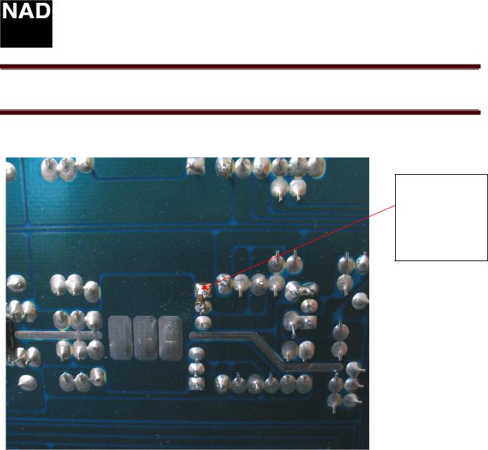
SOLUTION: Replace the transistor and install a 4700 pF capacitor between the base and collector on the pre amp pc board , as shown in the following two schematics. The use of a surface mount capacitor is recommended. Placing the capacitor on the bottom of the board between the base and collector of each muting transistor is preferred . See figure 2 on page 2.
Note: It is recommended to install this capacitor to each channel’s muting transistor.The following are the designations of the muting transistors, Q608,Q609,Q610,Q611,Q615,Q617.
Figure 1 |
muting circuit |
|
muting circuit |
|
Subwoofer/Multi. |
|
All other channels |
|
CH.’S |
|
|
|
|
|
Page 1 of 2
Technical Bulletin T743
Product: A/V Receiver
Hardware Technical Bulletin: T743-H2005-05R
Figure 2
4700pF surface mount capacitor between base and collector pins of muting transistor on the pre amp pc board
Contact:
NAD Electronics International 633 Granite Court
Pickering, ON Canada L1K 3K1
Voice: 905-831-0799 FAX 905-837-6357 www.nadelectronics.com
Page 2 of 2
Technical Bulletin T743
|
Product: |
A/V Receiver |
|
Hardware Technical Bulletin: T743-H2004-03 |
|
|
|
|
Date: |
June 1, 2004 |
Subject: HDTV Component |
|
|
Video change |
Note: |
Implemented in production from Serial number: R44 series and onwards |
|
Previous T.B.’s required:
TYES
TNO
DESCRIPTION: To improve the compatibility of HDTV signals with some TV/Monitors.
REASON: When decoding HDTV signals some TV/Monitors may experience horizontal sync loss.
SOLUTION: Perform the following change to the Component video board.
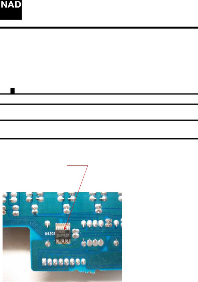
On the component video PCB U4301
A) Link the following pins on U4301;
Pins 9 to 10
Pins 12 to 13
Pins 14 to 15
Figure1
Page 1 OF 2

Technical Bulletin T743
Product: A/V Receiver
Hardware Technical Bulletin: T743-H2004-03
HDTV Component Video Change
B) Remove C4317, C4319, C4321.
Figure 2
C) Replace C4316, C4318, and C4320 with 1000 uF 6V.
Figure 3
Contact:
NAD Electronics International 633 Granite Court
Pickering, ON Canada L1K 3K1 Voice: 905-831-0799 FAX 905-837-6357 www.nadelectronics.com
Page 2 OF 2
 Loading...