

Page 1

MTS Fundamental™ Pneumatic Grip Controller
Manual Title
Additional Information
Product Manual
be certain.
100-231-449 A
Page 2

Copyright information © 2011 MTS Systems Corporation. All rights reserved.
Trademark information MTS is a registered trademark and MTS Criterion and MTS Fundamental are
trademark of MTS Systems Corporation within the United States. These
trademarks may be protected in other countries.
Teflon is a registered trademark of Dupont. All other trademarks or service marks
are property of their respective owners.
Publication information
MANUAL PART NUMBER PUBLICATION DATE
100-231-449 A January 2011
2
MTS Fundamental™ Pneumatic Grip Controller Product Manual
Page 3
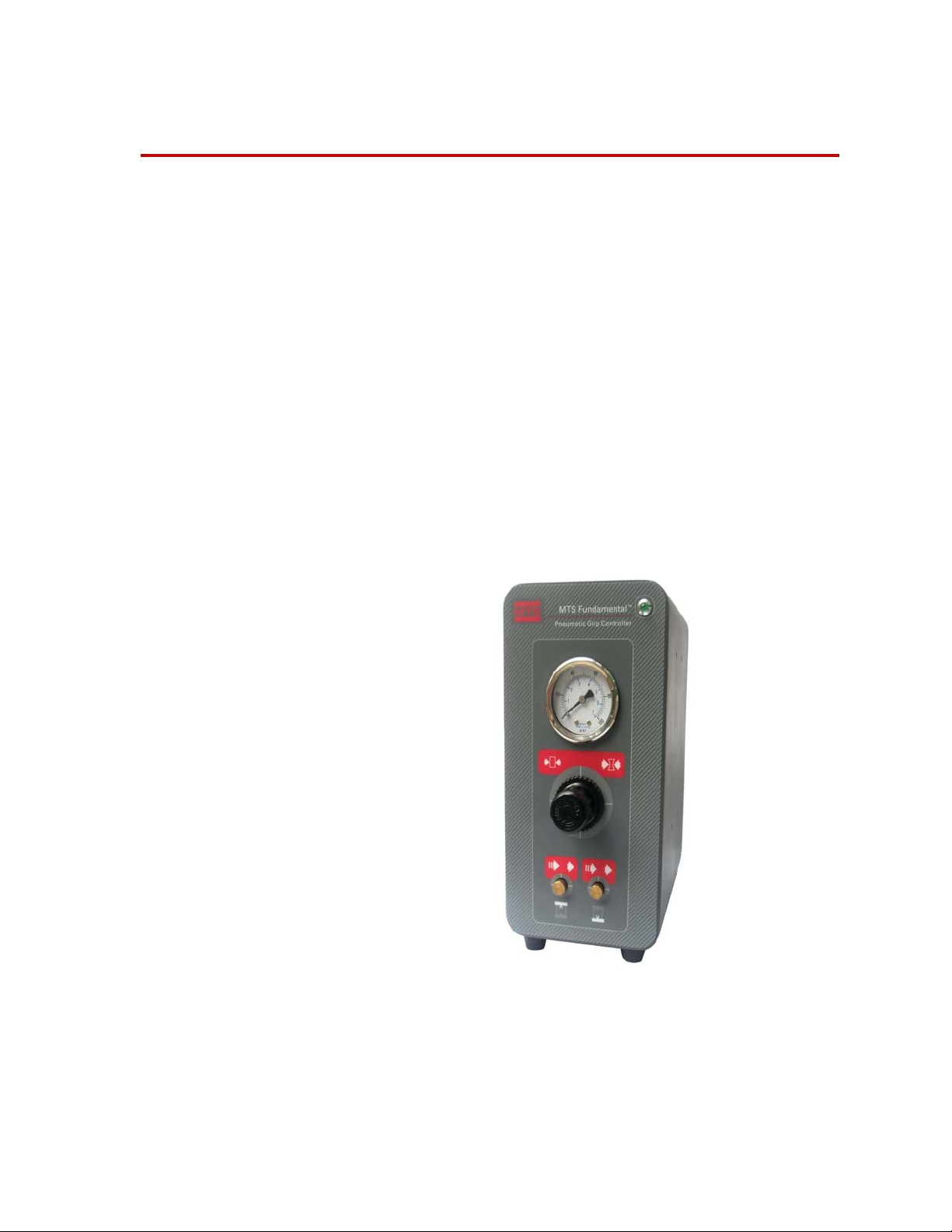
Pneumatic Grip Controller
Contents Safety 4
Control Panel Identification 5
Installation 7
Operation 8
Maintenance 9
Specifications 10
The pneumatic grip controller provides open/close function, air pressure
regulation, and flow control for pneumatic grips.
For grip operation, the unit comes with a foot switch. The foot switch sequence is
user-selectable for adaptable and efficient specimen loading. The controller
comes with temperature-resistant Teflon tubing for grip connections.
MTS Fundamental™ Pneumatic Grip Controller Product Manual
3
Page 4
Safety
Safety
General Safety Precautions
This section provides information about safety issues that pertain to pneumatic
grip controllers in general and a definition for the graphical hazard labeling that
is affixed to your product.
When you prepare to operate the pneumatic grip controller, consider the
following:
• Failure to use this equipment in accordance with the manufacturer’s
• Ensure the controller is off before connecting the pneumatic tubing.
• Always wear protective devices such as eye protectioin.
• Ensure air supply is properly filtered (see “Specifications” on page 10).
recommendations can result in unpredicatbale grip operation, which can
cause equipment damage or personal injury.
Hazard Placards
• Follow all precautions and safety information associated with you
pneumatic grips.
Hazard placards contain specific safety information and are affixed directly to the
system so they are plainly visible.
The following hazard action icons are used on MTS products. These icons
indicate recommended actions that will minimize the chance of personal injury or
equipment damage. They are typically placed on or near the area of concern.
They are intended to alert the user to actions that should be taken.
I
CON DESCRIPTION
General waring. Possible hazard(s) exists in
the vicinity where this icon is located. See
the manual for additional information.
Do not start, operation, or service pneumatic
grip controller until you read and understand
operator’s manual.
Failure to do so could result in serious
injury.
4
MTS Fundamental™ Pneumatic Grip Controller Product Manual
Page 5

Control Panel Identification
Front Panel
Control Panel Identification
1
2
3
4
ITEM CONTROL DESCRIPTION
1
2
3
4
5
Power/equipment indicator A continuously lit indicator indicates the pwoer is
OK; If the indicator keeps flashing, check the AC
power adapter.
Output air pressure (indicating
gage)
Pressure control (knob) Use the appropriate minimum pressure to grip the
Upper clamp closure rate control
(knob)
Lower clamp closure rate control
(knob)
MTS Fundamental Pneumatic Grips can withstand a
maximum pressure of 0.7 MPa (100 psi).
sample.
When adjusting this control, ensure the closure rate is
not so high as to damage fragile samples.
When adjusting this control, ensure the closure rate is
not so high as to damage fragile samples.
5
MTS Fundamental™ Pneumatic Grip Controller Product Manual
5
Page 6

Control Panel Identification
Back Panel
1
2
3
4
5
6
7
I
TEM CONTROL DESCRIPTION
1
2
3
4
Emergency stop output connector It is connected with emergency stop part by cable.
Emergency stop input connector It is connected with emergency stop part by cable.
Pneumatic tubing connections They are connected with grips.
Communications connector The host controls the communications connector which
supports the software.
5
6
Remote switch connector Foot switch connector.
DC power connector This power connector is used to power the pneumatic grip
controller.
7
Air input connector It is connected with air supply.
6
MTS Fundamental™ Pneumatic Grip Controller Product Manual
Page 7

Installation
Installation
1. Disconnect power to the pneumatic grip controller.
Note To release the tubing, press in the locking collar (see 3 on the previous
page) and pull the tubing out of the connection.
2. Using the supplied tubing and cutter, cut the tubing to the appropriate
length.
3. Push the tubing into the four grip connections firmly.
4. Connect the foot switch to the Switch Connection.
5. Firmly push the tubing into the Compressed Air Input.
6. Connect E-stop Input.
7. Connect E-stop Output. This connector allows you to pass the E-stop signal
to another device. If the pneumatic grip controller is the last device in the Estop chain, this connector must be terminated (jumpered).
MTS Fundamental™ Pneumatic Grip Controller Product Manual
7
Page 8

Operation
Operation
Use the foot switch to operate the pneumatic grip controller.
1. When you press the upper grip foot switch the first time, the upper grip is
closed. Press the switch again to release the grip.
2. When you press the lower grip foot switch the first time, the lower grip is
closed. Press the switch again to release the grip.
8
MTS Fundamental™ Pneumatic Grip Controller Product Manual
Page 9

Maintenance
Maintenance
• Ensure that the hose is tightly connected to the interface.
• When necessary, use a mild detergent and a soft cloth to clean the pneumatic
grip controller.
• When pneumatic tubing shows signs of wear, replace it. (MTS part number
11421170001) .
MTS Fundamental™ Pneumatic Grip Controller Product Manual
9
Page 10

Specifications
Specifications
ITEM SPECIFICATIONS
Requirements of input gas
Air pressure
Filtering
Dew point temperature
Power supply requirements to
Meanwell AC to 12 V DC power
supply
Input voltage
Input frequency
Input current
Peumatic tubing
External diameter
Temperature range
Material
MTS part number
Environmental requirements
Temperature
Less than 0.7 Mpa (100 psi)
Less than 15 μm
Less than 7°C (44.6°F)
100-240 V AC (single phase)
50/60 Hz
1.4 A
6 mm (15/64 inch)
-170°C to 260°C (-275°F to 500°F)
PTFE (plastic insulation material)
11421170001
5°C to 40 °C (41°F to 104°F)
10
Relative humidity
Altitude
5-85% non-condensing
Less than 2000 m (6,500 ft)
MTS Fundamental™ Pneumatic Grip Controller Product Manual
Page 11

Page 12

m
MTS Systems Corporation
http://www.mts.com/en/Global/index.asp
ISO 9001 Certified QMS
 Loading...