

Page 1

be certain.
m
Model 409.83 Temperature Controller
Product Information
015-058-901 F
Page 2

Copyright information © 1997, 2000, 2001, 2004, 2008 MTS Systems Corporation. All rights reserved.
Trademark information MTS is a registered trademark of MTS Systems Corporation within the United
States. This trademark may be protected in other countries.
Eurotherm is a registered trademark of Eurotherm Controls Ltd.
Publication information
Manual Part Number Publication Date
015-058-901 A August 1997
015-058-901 B March 2000
015-058-901 C October 2001
015-058-901 D March 2004
015-058-901 E June 2004
015-058-901 F March 2008
2
Manual Template 4.3
Page 3

Contents
EC Declaration of Conformity 5
Manufacturer/Importer: 6
Technical Support 7
How to Get Technical Support 7
Before You Contact MTS 7
If You Contact MTS by Phone 8
Problem Submittal Form in MTS Manuals 9
Preface 11
Before You Begin 11
Conventions 12
Documentation Conventions 12
Introduction 15
Model 409.83 Temperature Controller Functional Description 15
Model 409.83 Temperature Controller Specifications 16
Safety Information 19
Hazard Placard Placement 19
Installation 21
Model 409 High Temperature Controller Connections 22
Model 409.83 Temperature Controller Configuration 24
Model 409.83 Temperature Controller Calibration 25
Model 409.83 Temperature Controller
3
Page 4

Operation 27
Model 409.83 Temperature Controller Powerup 27
Model 409.83 Temperature Controller Controls and Indicators 28
Temperature Setpoints 29
Parameter Settings 30
About Alarms 31
Process Alarms 31
Diagnostic Alarms 32
Access Levels 32
Selecting an Access Level 33
Maintenance 35
Controller Settings 37
4
Model 409.83 Temperature Controller
Page 5

EC Declaration of Conformity
Description of Model MTS Model 409.83 Multizone Temperature Controller and 653.01, 02, 03, 04
Furnaces.
Manufacturer MTS Systems Corporation
14000 Technology Drive
Eden Prairie, MN, USA 55344
phone: 952-937-4000
European agent MTS Systems GmbH
Hohentwielsteig 3
14163 Berlin, Germany
phone: +49-30-810020
Test Standards Tests were performed to verify that this product met the Essential Requirements
of the Low Voltage directive 73/23/EEC and the EMC directive 89/336/EEC by
conforming to the following product specifications:
EN 61010-1:2001 and EN 61010-2-010:1994 Safety requirements for electrical
equipment for measurement, control and laboratory use, Part 1: General
requirements.
EN 61000-6-2 Electromagnetic compatibility, Generic immunity standard, Part
2: industrial environment (March 1999).
D
ESCRIPTION BASIC STANDARD TEST SPECIFICATION
Limits for harmonic current emissions EN 61000-3-2 / 2000 per EN 61000-6-2:1999
Limits for voltage fluctuations and flicker EN 61000-3-3 / 2001 per EN 61000-6-2:1999
Electrostatic discharge EN 61000-4-2 / 1995 4 kV contact discharge
8 kV air discharge
Radio frequency electromagnetic field,
amplitude modulated
Electrical fast transient EN 61000-4-4 / 1995 2 kV control, signal, and mains
Surge immunity test EN 61000-4-5 / 1995 2 kV mains
Radio frequency common mode, amplitude
modulated
Power frequency magnetic field EN 61000-4-8 / 1993 30 A/m
Voltage dips, short interruptions and
voltage variations
EN 61000-4-3 / 1993 10 V/m
EN 61000-4-6 / 1993 10 Vrms
EN 61000-4-11 / 1994 per EN 61000-6-2:1999
Model 409.83 Temperature Controller EC Declaration of Conformity
5
Page 6

Manufacturer/Importer:
Manufacturer/Importer:
Signed:
Name: Leo Kühhass
Title: European Operations Manager
EN 55011 Specification for limits and methods of measurement of radio
disturbance characteristics of industrial, scientific and medical (ISM) radio
frequency equipment (1991). Group 1, class A (non-domestic where RF is NOT
used in the treatment of material).
ASIC STANDARD DESCRIPTION
B
Radiated emissions EN 55011
Conducted emissions EN 55011
Date: May 12, 2004
EC Declaration of Conformity
6
Model 409.83 Temperature Controller
Page 7

Technical Support
How to Get Technical Support
How to Get Technical Support
Start with your
manuals
Technical support
methods
MTS web site
www.mts.com
E-mail techsupport@mts.com
Telephone MTS Call Center 800-328-2255
Fax 952-937-4515
The manuals supplied by MTS provide most of the information you need to use
and maintain your equipment. If your equipment includes MTS software, look
for online help and README files that contain additional product information.
If you cannot find answers to your technical questions from these sources, you
can use the internet, e-mail, telephone, or fax to contact MTS for assistance.
MTS provides a full range of support services after your system is installed. If
you have any questions about a system or product, contact MTS in one of the
following ways.
The MTS web site gives you access to our technical support staff by means of a
Technical Support link:
www.mts.com > Contact Us > Service & Technical Support
Weekdays 7:00 A.M. to 5:00 P.M., Central Time
Please include “Technical Support” in the subject line.
Before You Contact MTS
MTS can help you more efficiently if you have the following information
available when you contact us for support.
Know your site
number and system
number
Model 409.83 Temperature Controller Technical Support
The site number contains your company number and identifies your equipment
type (material testing, simulation, and so forth). The number is usually written on
a label on your MTS equipment before the system leaves MTS. If you do not
have or do not know your MTS site number, contact your MTS sales engineer.
Example site number: 571167
When you have more than one MTS system, the system job number identifies
which system you are calling about. You can find your job number in the papers
sent to you when you ordered your system.
Example system number: US1.42460
7
Page 8

If You Contact MTS by Phone
Know information from
prior technical
If you have contacted MTS about this problem before, we can recall your file.
You will need to tell us the:
assistance
• MTS notification number
• Name of the person who helped you
Identify the problem Describe the problem you are experiencing and know the answers to the
following questions:
• How long and how often has the problem been occurring?
• Can you reproduce the problem?
• Were any hardware or software changes made to the system before the
problem started?
• What are the model numbers of the suspect equipment?
• What model controller are you using (if applicable)?
• What test configuration are you using?
Know relevant
computer information
If you are experiencing a computer problem, have the following information
available:
• Manufacturer’s name and model number
• Operating software type and service patch information
• Amount of system memory
• Amount of free space on the hard drive in which the application resides
• Current status of hard-drive fragmentation
• Connection status to a corporate network
Know relevant
For software application problems, have the following information available:
software information
• The software application’s name, version number, build number, and if
available, software patch number. This information is displayed briefly
when you launch the application, and can typically be found in the “About”
selection in the “Help” menu.
• It is also helpful if the names of other non-MTS applications that are
running on your computer, such as anti-virus software, screen savers,
keyboard enhancers, print spoolers, and so forth are known and available.
If You Contact MTS by Phone
Your call will be registered by a Call Center agent if you are calling within the
United States or Canada. Before connecting you with a technical support
specialist, the agent will ask you for your site number, name, company, company
address, and the phone number where you can normally be reached.
Technical Support
8
Model 409.83 Temperature Controller
Page 9

Problem Submittal Form in MTS Manuals
If you are calling about an issue that has already been assigned a notification
number, please provide that number. You will be assigned a unique notification
number about any new issue.
Identify system type To assist the Call Center agent with connecting you to the most qualified
technical support specialist available, identify your system as one of the
following types:
• Electromechanical materials test system
• Hydromechanical materials test system
• Vehicle test system
• Vehicle component test system
• Aero test system
Be prepared to
Prepare yourself for troubleshooting while on the phone:
troubleshoot
• Call from a telephone when you are close to the system so that you can try
implementing suggestions made over the phone.
• Have the original operating and application software media available.
• If you are not familiar with all aspects of the equipment operation, have an
experienced user nearby to assist you.
Write down relevant
Prepare yourself in case we need to call you back:
information
• Remember to ask for the notification number.
• Record the name of the person who helped you.
• Write down any specific instructions to be followed, such as data recording
or performance monitoring.
After you call MTS logs and tracks all calls to ensure that you receive assistance and that action
is taken regarding your problem or request. If you have questions about the status
of your problem or have additional information to report, please contact MTS
again and provide your original notification number.
Problem Submittal Form in MTS Manuals
Use the Problem Submittal Form to communicate problems you are experiencing
with your MTS software, hardware, manuals, or service which have not been
resolved to your satisfaction through the technical support process. This form
includes check boxes that allow you to indicate the urgency of your problem and
your expectation of an acceptable response time. We guarantee a timely
response—your feedback is important to us.
The Problem Submittal Form can be accessed:
• In the back of many MTS manuals (postage paid form to be mailed to MTS)
• www.mts.com > Contact Us > Problem Submittal Form (electronic form to
be e-mailed to MTS)
Model 409.83 Temperature Controller Technical Support
9
Page 10

Problem Submittal Form in MTS Manuals
Technical Support
10
Model 409.83 Temperature Controller
Page 11

Before You Begin
Preface
Before You Begin
Safety first! Before you attempt to use your MTS product or system, read and understand the
Safety manual and any other safety information provided with your system.
Improper installation, operation, or maintenance of MTS equipment in your test
facility can result in hazardous conditions that can cause severe personal injury or
death and damage to your equipment and specimen. Again, read and understand
the safety information provided with your system before you continue. It is very
important that you remain aware of hazards that apply to your system.
Other MTS manuals In addition to this manual, you may receive additional MTS manuals in paper or
electronic form.
If you have purchased a test system, it may include an MTS System
Documentation CD. This CD contains an electronic copy of the MTS manuals
that pertain to your test system, including hydraulic and mechanical component
manuals, assembly drawings and parts lists, and operation and preventive
maintenance manuals. Controller and application software manuals are typically
included on the software CD distribution disc(s).
Model 409.83 Temperature Controller Preface
11
Page 12
Conventions
DANGER
WARNING
CAUTION
Conventions
Documentation Conventions
The following paragraphs describe some of the conventions that are used in your
MTS manuals.
Hazard conventions As necessary, hazard notices may be embedded in this manual. These notices
contain safety information that is specific to the task to be performed. Hazard
notices immediately precede the step or procedure that may lead to an associated
hazard. Read all hazard notices carefully and follow the directions that are given.
Three different levels of hazard notices may appear in your manuals. Following
are examples of all three levels.
Note For general safety information, see the safety information provided with
your system.
Danger notices indicate the presence of a hazard with a high level of risk which,
if ignored, will result in death, severe personal injury, or substantial property
damage.
Warning notices indicate the presence of a hazard with a medium level of risk
which, if ignored, can result in death, severe personal injury, or substantial
property damage.
Caution notices indicate the presence of a hazard with a low level of risk which,
if ignored, could cause moderate or minor personal injury, equipment damage, or
endanger test integrity.
Notes Notes provide additional information about operating your system or highlight
easily overlooked items. For example:
Note Resources that are put back on the hardware lists show up at the end of
the list.
Special terms The first occurrence of special terms is shown in italics.
Illustrations Illustrations appear in this manual to clarify text. It is important for you to be
Electronic manual
conventions
Preface
12
aware that these illustrations are examples only and do not necessarily represent
your actual system configuration, test application, or software.
This manual is available as an electronic document in the Portable Document
File (PDF) format. It can be viewed on any computer that has Adobe Acrobat
Reader installed.
Model 409.83 Temperature Controller
Page 13

Documentation Conventions
Hypertext links The electronic document has many hypertext links displayed in a blue font. All
blue words in the body text, along with all contents entries and index page
numbers, are hypertext links. When you click a hypertext link, the application
jumps to the corresponding topic.
Model 409.83 Temperature Controller Preface
13
Page 14

Documentation Conventions
14
Preface
Model 409.83 Temperature Controller
Page 15

Introduction
Eurotherm Model 2216
Temperature Control
Modules
Model 409.83 Temperature Controller Functional
The MTS Model 409.83 Temperature Controller is a microprocessor-based
controller for use with MTS Model 652 and 653 High-Temperature Furnaces. It
may be mounted on a table top or on a load unit.
Model 409.83 Temperature Controller
Inappropriate use Before you attempt to use the Model 409.83 High Temperature Controller, read
and understand this manual. Improper installation or operation of this product
can result in hazardous conditions that can cause severe personal injury or death,
and damage your equipment and specimen.
WEEE The Waste Electrical and Electronic Equipment (WEEE) symbol ( ) means
that the controller and its electronic parts must not be disposed of as unsorted
municipal waste. Proper disposal is required by approved electronic waste
collection agencies. Customers in the EC region who desire to return an end-oflife controller and its electronic parts are encouraged to contact your local MTS
Systems Sales/Service Offices for instructions.
Model 409.83 Temperature Controller Functional Description
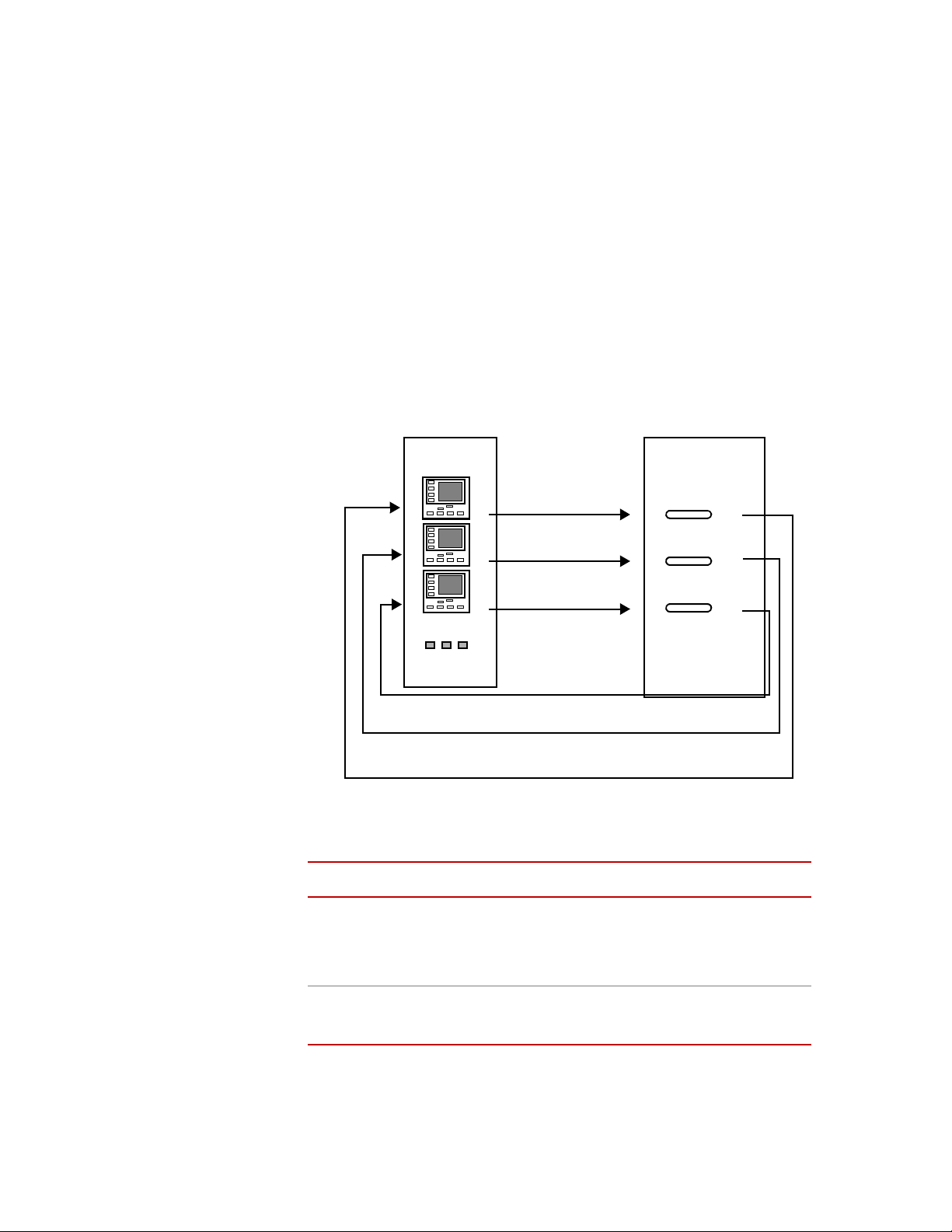
Closed-loop control is maintained in each zone by a single Eurotherm Model
2216 Temperature Controller (control module). The Model 409.83 Temperature
Controller includes up to three Eurotherm control modules which correspond to
up to three heat zones in the furnace. Each module accepts a thermocouple input
and outputs proportional power to control the respective furnace heating element.
The control modules are programmed at MTS for use with Series 652 or 653
High-Temperature Furnaces. Tuning parameters establish the temperature
setpoint, control accuracy, and operating limits. Alarm circuits function as an
Model 409.83 Temperature Controller Introduction
15
Page 16
Model 409.83 Temperature Controller Specifications
High
Temperature
Furnace
Upper Control
Signal
Middle Control
Signal
Lower Control
Signal
Lower Thermocouple
Signal
Middle Thermocouple Signal
Upper Thermocouple Signal
element
element
element
Temperature
Controller
interlock when the heater elements are enabled. If undesirable conditions arise,
power to the heater elements is cut off automatically.
The following figure illustrates a block diagram of the Model 409.83
Temperature Controller and a high-temperature furnace.
A temperature setpoint is selected for each furnace heat zone. The setpoint is
compared to the temperature measurement provided by a thermocouple inside in
the furnace. Any difference (between the setpoint and the actual temperature)
causes an error signal.
The error signal produces a time proportional signal. This time proportional
signal is sent to a corresponding solid state relay. The time proportional output
pulses the solid state relay on and off at a rate determined by the amplitude and
polarity of the error signal. The solid state relay applies the AC power to the
corresponding heating element in the furnace.
Model 409.83 Temperature Controller Specifications
Introduction
16
Environmental:
Line Voltage
Parameter
Tem per atu re
Relative Humidity
†
Specification
0°C to 50°C (32°F to 122°F)
10 to 90%, noncondensing
100–120 V AC± 10%, 50/60 Hz
220–240 V AC± 10%, 50/60 Hz
Model 409.83 Temperature Controller
*
Page 17

Model 409.83 Temperature Controller Specifications
Parameter
Line Current
1 zone
2 zone
3 zone
Cable length, AC line cord Approximately 2.4 m (8 ft.)
Cable length, Control to Furnace Maximum 3.96 m (13 ft.)
Operating Temperature, Furnace 100°C to 1400°C (212°F–2552°F)
Number of Zones 1, 2, or 3
Thermocouple Type R
* Specifications are subject to change without notice. Contact MTS for
verification of specifications critical to you needs.
† The Model 409.83 Temperature Controller line voltage must be specified
at time of order (it is not field selectable). The AC line voltage
specification listed conforms to the CE low-voltage directive. The
specification allows for ±10% of the values listed.
100–120 V 220–240 V
8 A 4 A
16 A 8 A
N/A 12 A
Specification
*
Model 409.83 Temperature Controller Introduction
17
Page 18

Model 409.83 Temperature Controller Specifications
18
Introduction
Model 409.83 Temperature Controller
Page 19

Safety Information
This unit
wired for
100-120 V~
50/60 Hz
16 amp
This unit
wired for
220-240 V~
50/60 Hz
12 amp
This unit
wired for
220-240 V~
50/60 Hz
8 amp
Left
Furnace
Right
Furnace
J5
J4
This unit
wired for
100-120 V~
50/60 Hz
8 amp
This unit
wired for
220-240 V~
50/60 Hz
4 amp
J6
Upper Lower
J6
Lower
Upper Mid
Hazard Placard Placement
Hazard placards contain specific safety information and are affixed directly to the
system so they are plainly visible.
Each placard describes a system-related hazard. When possible, international
symbols (icons) are used to graphically indicate the type of hazard and the
placard label indicates its severity. In some instances, the placard may contain
text that describes the hazard, the potential result if the hazard is ignored, and
general instructions about how to avoid the hazard.
The following labels are typically located on the controller.
L
ABEL DESCRIPTION
Identification label.
Hazard Placard Placement
Part # 002-680-701
Contains the following information:
• MTS contact information
• Year manufactured
• Final assembly number
• Model
• Serial number
A combination of these information
labels may appear somewhere on the
controller.
Label Set Part # 052-546-801
Model 409.83 Temperature Controller Safety Information
19
Page 20

Hazard Placard Placement
Safety Information
20
Model 409.83 Temperature Controller
Page 21

Installation
CAUTION
This chapter provides installation information for the Model 409.83 Temperature
Controller.
Do not use this controller with incompatible furnaces.
The temperature controller is programmed for use with the Model 652 or 653 High
Temperature Furnaces. The heating elements of older furnaces could be
damaged if used with this temperature controller.
Note The 409.83 is a class 1 LED product as defined by the CE low voltage
directive.
Mounting
considerations
The Model 409.83 Temperature Controller can be mounted on a table top (with
an optional table top bracket) or floor stand. The temperature controller must be
mounted such that the lamps on the controller are visible from the furnace.
1. Ensure that the temperature controller has arrived with no shipping damage.
If damaged, contact the Customer Service division of MTS Systems
Corporation.
2. Locate the table-top or floor stand that accompanied the controller. Mount
the temperature controller to it using the nuts and bolts provided.
3. Connect cables and wires per the cable assembly drawing.
AC power disconnect Turn off the AC power switch. Remove the AC power cord from the unit. This
will remove all AC power from the chassis.
Note Be sure to locate the chassis so that you have adequate access to
disconnect the power cord form the chassis.
Model 409.83 Temperature Controller Installation
21
Page 22

Model 409 High Temperature Controller Connections
WARNING
Platinum/Rhodium (Black)
Platinum (Red)
From
Thermocouple
+
–
Model 409 High Temperature Controller Connections
All input/output signals that interface the temperature controller and other system
components are available on the bottom panel. This section provides information
on all input/output signals of the temperature controller.
Model 409.83 Temperature Controller Bottom Panel
The furnace/controller must be connected to a supply source which
incorporates a residual current operated circuit-breaker which interrupts the
supply at a differential current of 30mA or less.
Due to the fact that the heaters are hazardous live and are accessible, the
equipment must be connected to a supply source that incorporates such a circuit
breaker.
Chassis voltage The temperature controller receives power from a detachable, three-wire power
cord. The power cord plugs into an input power connector block located on the
bottom panel. The chassis power switch is located on the rear panel; on is labeled
|, and off is labeled 0. The line voltage is selected at time of order (120 or 240 V)
and is not field selectable.
J1, J2, J3
thermocouple inputs
Temperature feedback is provided through a single Type ‘R’ thermocouple lead
(for each zone). The furnace thermocouples should be connected to the input
connectors. The connections are polarized; the longer slot is negative (–) and the
shorter slot is positive (+).
22
Installation
J1, J2, and J3 Thermocouple Input Connections
Model 409.83 Temperature Controller
Page 23

Model 409 High Temperature Controller Connections
Left
Furnace
Right
Furnace
J4, J5 heating element
outputs
J6 serial
communication
Socket-style connectors J4 and J5 transfer the heater control signal (line voltage)
from the temperature controller to the furnace heater elements. The cables
connected to J4 and J5 are interchangeable.
J4 and J5 Heating Element Output Connections
The J6 serial communication port has three functions:
• Interlock input
The interlock input can be connected to an external (normally-closed)
switch or contact. If the external switch or contact opens, the temperature
controller alarm is triggered, and power is cut off to the heating elements.
• Interlock contact output
The interlock output (relay output) can be connected to an external
monitoring device to follow the enable/alarm state of the temperature
controller. This contact is closed when the Model 409.83 Controller heating
elements are enabled. If an alarm is triggered or the Disable button is
pressed (interlock is open), a signal is sent to the external monitoring device.
• RS–485 communication port to temperature control module
All functions and readout values in each Eurotherm 2216 Controller can be
monitored and adjusted by a single RS-485 serial port located at J6.
If nothing is connected to the J6 port, a jumper plug must be installed (MTS part
number 525099-01).
J6 Serial Communication Connection
Model 409.83 Temperature Controller Installation
23
Page 24

Model 409.83 Temperature Controller Configuration
CAUTION
Model 409.83 Temperature Controller Configuration
Through the configuration level you can set up the fundamental characteristics of
the controller. These include:
• The type of control
• The input type and range
• The alarm functions
• The output functions
• The communications configuration
• Calibration
• Passwords
Selecting an access
level
1. Access the configuration level.
• If the controller is powered up, select the appropriate configuration
level.
• If the controller is not powered up, press and hold the up and down
arrows simultaneously while powering up the controller. This takes you
directly to the ConF password entry display.
2. At the PASS prompt, enter the configuration password.
The password is initially factory-set to 2.
Note Refer to the Eurotherm Model 2216 Temperature Controller manual for
information on changing passwords.
3. Press the scroll button.
The first display of the configuration will be shown.
A. To return to the operator access level from the ConF access level, press
the page and scroll buttons simultaneously. At the Exit prompt, use the
up or down arrows to select Ye s . This will return you to the Home
display in the operator access level.
24
Installation
Configuration is protected by password and should only be carried out by
qualified persons.
Incorrect configuration could result in damage to the process being controlled or
personal injury.
Note For complete information on parameter availability (including navigation
diagrams), refer to the Eurotherm Model 2216 Temperature Controller
manual.
Model 409.83 Temperature Controller
Page 25

Model 409.83 Temperature Controller Calibration
Model 409.83 Temperature Controller Calibration
The basic calibration of the controller is highly stable and set for life. User
calibration allows you to offset the permanent factory calibration to either:
• Calibrate the controller to your reference standards.
• Match the calibration of the controller to that of a particular transducer or
sensor input.
• Calibrate the controller to suit the characteristics of a particular installation
• Remove long term drift in the factory-set calibration.
User calibration works by introducing zero and span offsets onto the factory-set
calibration.
Note For complete information on enabling and performing user calibration,
refer to the Eurotherm Model 2216 Temperature Controller manual.
Model 409.83 Temperature Controller Installation
25
Page 26

Model 409.83 Temperature Controller Calibration
26
Installation
Model 409.83 Temperature Controller
Page 27

Operation
WARNING
2216
OP1
OP2
SP2
REM
26.0
20.0
Measured
temperature
Setpoint
EUROTHERM
This chapter provides operational procedures and a functional description of the
Model 409.83 Temperature Controller front panel and indicators.
The protection provided by this equipment can be impaired if this furnace is
not used in its intended manner.
Do not operate the furnace in a manner contrary to its intended use.
Model 409.83 Temperature Controller Powerup
When the temperature controller is turned on, each control module goes through
a self-test sequence that takes approximately three seconds. When the test
sequence is completed, the control module defaults to the “Home” display. The
Home display indicates the actual temperature (or process value) in the upper
readout and the temperature setpoint in the lower readout (see the following
figure).
Model 409.83 Temperature Controller Powerup
Home Display
If the controller detects an alarm condition, the yellow alarm indicator
illuminates, and the control module flashes an alarm message in either the upper
or lower readout of the Home display.
Model 409.83 Temperature Controller Operation
27
Page 28

Model 409.83 Temperature Controller Controls and
Disable Enable Alarm
2216
EUROTHERM
MAN
OP1
SP2
REM
OP2
RUN
1
2
3
4
5
6
7
14
13
12
9
10
8
Top of controller
11
Model 409.83 Temperature Controller Controls and Indicators
The following figure illustrates the lower part of the Model 409.83 Temperature
Controller front panel.
.
C
ALLOUT CONTROL OR
I
NDICATOR
Note There are two control modules on a two-zone and three control modules
1 OP1 Output 1
2 OP2 Output 2
28
Operation
Front Panel Layout
on a three-zone temperature controller.
Controls and Indicators
NAME DESCRIPTION
When lit, it indicates that output 1 is on. This is normally
the heating output.
When lit, it indicates that output 2 is on. This is normally
the cooling output, and it is not connected on typical
systems.
Model 409.83 Temperature Controller
Page 29

Controls and Indicators (Continued)
Temperature Setpoints
ALLOUT CONTROL OR
C
I
NDICATOR
3 SP2 Setpoint 2
4REM Remote
5MAN Manual
6 Page Button
7Scroll Button
8 Down Button
NAME DESCRIPTION
When lit, this indicates that setpoint 2 has been selected.
When lit, this indicates that the PDSIO remote setpoint
Setpoint
input has been selected.
When lit, it indicates that manual mode has been
Mode
selected.
Press to select a new list of parameters.
Press to select a new parameter in a list.
Press to decrease a value in the lower readout.
To speed up the rate of change, press and hold the button.
9 Up Button
Press to increase a value in the lower readout.
To speed up the rate of change, press and hold the button.
10 RUN Run Indicator
When lit, it indicates that setpoint rate limit is active.
11 LCD Display Readout
12 Switch/Indicator
(red)
13 Switch/Indicator
(green)
14 Indicator (yellow) Alarm
Not
Shown
Power Switch I / O
Disable
Enable
Temperature Setpoints
Normal operation of the temperature controller requires the desired temperature
setpoints to be entered into each control module. After the setpoints have been
entered, the heater elements can be enabled.
To enter the temperature setpoints:
1. From the Home display, press the up or down arrow (to increase or decrease
the current value).
Displays temperature controller data (temp readout,
setpoint, parameter value, and so forth.)
Disables the heating elements of the high-temperature
furnace.
Enables the heating elements of the high-temperature
furnace.
Functions in conjunction with the alarm indicators of
each temperature controller. When the interlock is
broken, the Alarm indicator lights, and power to the
elements is cut off.
Chassis power switch (on back panel). On is labeled I,
Off is labeled O.
Model 409.83 Temperature Controller Operation
29
Page 30

Parameter Settings
2216
OP1
OP2
SP2
REM
AL
LiSt
List header
Always displays
‘LiSt’
Parameter Settings
Two seconds after releasing either button, the display blinks to show the
control module has accepted the new value.
2. Repeat step 1 for each control module.
You can return to the Home display by pressing the scroll and page buttons
simultaneously. Alternatively, you will always be returned to the Home
display if no button is pressed for 45 seconds.
3. Press the Enable Heater Elements switch.
This will bring the furnace up to temperature.
Note Parameters are set at MTS Systems according to the configuration
drawing at the end of the manual. If a control module is replaced, set the
parameters according to the MTS-factory settings and then run the
Eurotherm Automatic Tuning. Once the MTS factory settings have been
entered, you may deviate from them (in small steps).
Parameters are settings within the control module that determine how the control
module will operate. For example, alarm setpoints are parameters that determine
when alarms will occur. Parameters are arranged in lists. The names of these lists
are found in the list headers. The available lists are:
Home List Set Point List On/Off List
Alarm List Input List Communications List
PID List Output List Access List
Typical List Header Display
Note Refer to the Eurotherm Model 2216 product manual shipped with this
manual for a listing of the parameters available under each list header.
To change the value of a parameter:
30
Operation
1. From the Home display, press the page button to select the appropriate list
header.
Model 409.83 Temperature Controller
Page 31

About Alarms
About Alarms
Lists always show LiSt in the lower readout.
2. From the list header display, press the scroll button to select the required
parameter.
The parameter name displays in the upper readout and its value in the lower.
3. From the parameter display, press the up or down arrow (to increase or
decrease the current value).
Two seconds after releasing either button, the display blinks to show the
control module has accepted the new value.
4. Repeat Steps 1–3 for each parameter in each control module.
You can return to the Home display by pressing the scroll and page buttons
simultaneously. Alternatively, you will always be returned to the Home
display if no button is pressed for 45 seconds.
If any of the temperature controllers detect an alarm condition, two indicators
notify the operator.
Process Alarms
The alarm indicator on the lower panel lights, and an alarm message flashes in
either the upper or lower readout of the Home display. Alarms can be
acknowledged by pressing the page or scroll buttons on the display on the
affected control module.
On the control modules, new alarms are displayed as a double flash, followed by
a pause. If there is more than one alarm, the display cycles through the relevant
alarm conditions.
There are two types of alarms: Process and Diagnostic.
Process alarms warn of a problem with the process being monitored by the
controller.
Process Alarms
ALARM DISPLAY
-FSH Full Scale High Alarm
–FSL Full Scale Low Alarm
–dHi Deviation High Alarm
†
DESCRIPTION
*
–dLo Deviation Low Alarm
–dEV Deviation Band Alarm
Model 409.83 Temperature Controller Operation
31
Page 32

Diagnostic Alarms
Diagnostic Alarms
* Refer to the Eurotherm Model 2216 Temperature Controller manual
shipped with this manual for information on how to correct alarm
conditions.
† In place of the dash, the first character will indicate the alarm number.
Diagnostic alarms indicate that a fault exists in either the controller or other
connected devices.
Diagnostic Alarms
ALARM DISPLAY DESCRIPTION
EE.Er
S.br
L.br
Ld.F
SSr.F
Htr.F
HW.Er
rmt.F
LLLL
HHHH
Err1
Err2
Err3
Electrically Erasable Memory Error
Sensor Break
Loop Break
Load Failure
Solid State Relay Failure
Heater failure
Hardware error
Remote input failure
Out of range low reading
Out of range high reading
Error 1: ROM self-test failure
Error 2: RAM self-test failure
Error 3: Watchdog fail
*
Access Levels
Operation
32
Err4
Err5
Pwr.F
* Refer to the Eurotherm Model 2216 Temperature Controller manual
shipped with this manual for information on how to correct alarm
conditions.
Error 4: Keyboard failure
Error 5: Input circuit failure
Power failure (low line voltage)
Access levels provide the ability to restrict parameter changes. There are four
levels of access in the temperature controller:
• Operator Level
Model 409.83 Temperature Controller
Page 33

• Full Level
• Edit Level
• Configuration Level
Full, Edit, and Configuration levels are password-protected to prevent
unauthorized access.
Selecting an Access Level
To select an access level:
1. From the Home display, press the page button until you see the ACCS list
Selecting an Access Level
• Allows viewing and editing of parameters defined in the Edit level.
• Allows viewing and editing of all parameters.
• Allows you to set which parameters are accessible in the Operator
level.
• Allows you to set up the fundamental characteristics of the controller.
header.
Editing the
operator access
2. Press the scroll button.
The display will read CODE. Enter the password using the up and down
keys (the password is set to 1 when the unit is shipped from the factory).
Once the correct password is entered, the lower display will read PASS,
indicating that the access level is unlocked.
Note Refer to the Eurotherm Model 2216 Temperature Controller manual for
information on changing passwords.
3. Press the scroll button to proceed to the GOTO display.
4. From the GOTO display, press the up or down arrows to select the desired
access level.
There are four access levels available:
• OPER Operator level
• FULL Full level
• EDIT Edit level
• CONF Configuration level
In the edit access level, you can set which parameters are accessible in the
Operator access level and/or accessible from the Home display. To set operator
access to a parameter:
1. Select the Edit level.
2. Select the parameter to be set by toggling through the list headers (page
button) and selecting the parameter (scroll button).
Model 409.83 Temperature Controller Operation
33
Page 34

Selecting an Access Level
3. Once the parameter has been selected, use the up and down arrows to set the
parameter availability in Operator level.
There are four codes available:
• ALTR Makes a parameter alterable in Operator level
• PRO Promotes a parameter to the Home list display
• READ Makes a parameter or list header read-only
• HIDE Hides a parameter or list header
Returning to
operator level
To return to operator level from either FULL or EDIT level, repeat entry of
password and select OPER on the GOTO display. In Edit level, the control
module will automatically return to operator level if no button is pressed for 45
seconds.
34
Operation
Model 409.83 Temperature Controller
Page 35

Maintenance
CAUTION
Cleaning Keep the exterior of the temperature controller free from dust and other debris.
Should the controller require cleaning, keep the following points in mind:
Do not clean the controller exterior with harsh detergents.
Use only a soft cloth to clean the exterior of the controller. If a cleaning agent is
needed, use only mild detergent with water. Harsh detergents can damage the
temperature controller finish and electronics.
• Power should be disconnected (by unplugging the AC line cord at the wall
outlet) before cleaning.
• Use a soft cloth to remove dust and other debris from the exterior of the
temperature controller. If a cleaning agent is required, use only a mild
detergent and water.
• Allow for sufficient dry time before reconnecting power to the temperature
controller.
Replacing a Eurotherm
2216
Parameters are set at MTS Systems Corporation according to the configuration
drawing (MTS part number 531124-xx). If a control module is replaced, set the
parameters according to the MTS-factory settings and then run the Eurotherm
Automatic Tuning. Once the MTS factory settings have been entered, you may
deviate from them (in small steps).
Model 409.83 Temperature Controller Maintenance
35
Page 36

36
Maintenance
Model 409.83 Temperature Controller
Page 37

Controller Settings
Model 409.83 Temperature Controller Controller Settings
37
Page 38

Controller Settings
38
Model 409.83 Temperature Controller
Page 39

Page 40

m
MTS Systems Corporation
14000 Technology Drive
Eden Prairie, Minnesota 55344-2290 USA
Toll Free Phone: 800-328-2255
(within the U.S. or Canada)
Phone: 952-937-4000
(outside the U.S. or Canada)
Fax: 952-937-4515
E-mail: info@mts.com
Internet: www.mts.com
ISO 9001 Certified QMS
 Loading...