

Page 1

316 Load Frame
Product Information
l
100-105-843 B
Page 2

Copyright information © 2008 MTS Systems Corporation. All rights reserved.
Trademark information MTS is a registered trademark of MTS Systems Corporation.
Contact information MTS Systems Corporation
14000 Technology Drive
Eden Prairie, Minnesota 55344-2290 USA
Toll Free Phone: 800-328-2255 (within the U.S. or Canada)
Phone: 952-937-4000 (outside the U.S. or Canada)
Fax: 952-937-4515
E-mail: info@mts.com
http://www.mts.com
Publication information
Manual Part Number Publication Date
100-105-843 A
100-105-843 B
January 2003
April 2008
Page 3

Contents
Introduction 5
Functional Description 6
Specification 9
Direct Shear Capability 11
Operation 13
Hydraulic Configurations 13
Specimen Mounting Considerations 14
Uniaxial Configuration 15
Installation of Hardware 15
Installation of spacers as required 16
Specimen installation 17
Specimen removal 18
Tri-axial Configuration 19
Installation of Hardware 19
Tri-axial Cell Initial Installation 22
Installation of the specimen into the triaxial cell 24
Specimen removal in the triaxial cell configuration 27
Direct Shear Configuration 28
Installation of Hardware 28
Installation of the Direct Shear hardware 29
Direct Shear Specimen Preparation 30
Direct Shear Specimen Insertion into the Test Space 31
Direct Shear Specimen Removal from Test Space 32
Test specimen removal from specimen box 33
Maintenance 35
Making Daily Inspections 35
Preventing Rust 36
Checking the Accumulators’ Precharge Pressures 37
Servicing the Actuator 38
Installation 39
Series 316 Load Frame Product Information
3
Page 4

Unpacking and Inspection 39
Lifting and Moving Instructions 40
Installation of Load Frame 41
4
Series 316 Load Frame Product Information
Page 5

Introduction
The MTS Series 316 Load Frame Assembly is used to apply axial loads to rock
or concrete specimens for unaxial compression, tension, and fracture mechanics
tests. The assembly consists of a fixed crosshead mounted on four columns,
which are bolted to the base plate, resulting in a rigid, yet freestanding frame.
The four-column design allows access to the test area from all four sides for easy
insertion and removal of a wide range of specimen sizes and fixtures. Plastic
curtains on three sides and a front door enclose the test area. The test area height
is adjusted by using spacer plates for uniaxial testing. The load frame itself rests
on a rigid table to provide a convenient working height.
When a triaxial cell is inserted into the test space, the Series 316 Load Frame
actuator applies axial stress to the specimen inside the triaxial cell. Alternatively,
a horizontal loading assembly that includes a horizontal actuator can be attached
to the axial load frame to provide a shearing load for direct shear tests. In this
configuration, the Series 316 Load Frame actuator applies the normal load.
The load frame assembly is available in four standard sizes based on load
capacity. Choosing a load frame depends on the strength and size of the material
being tested and the testing requirements.
Series 316 Load Frame Product Information Introduction
5
Page 6
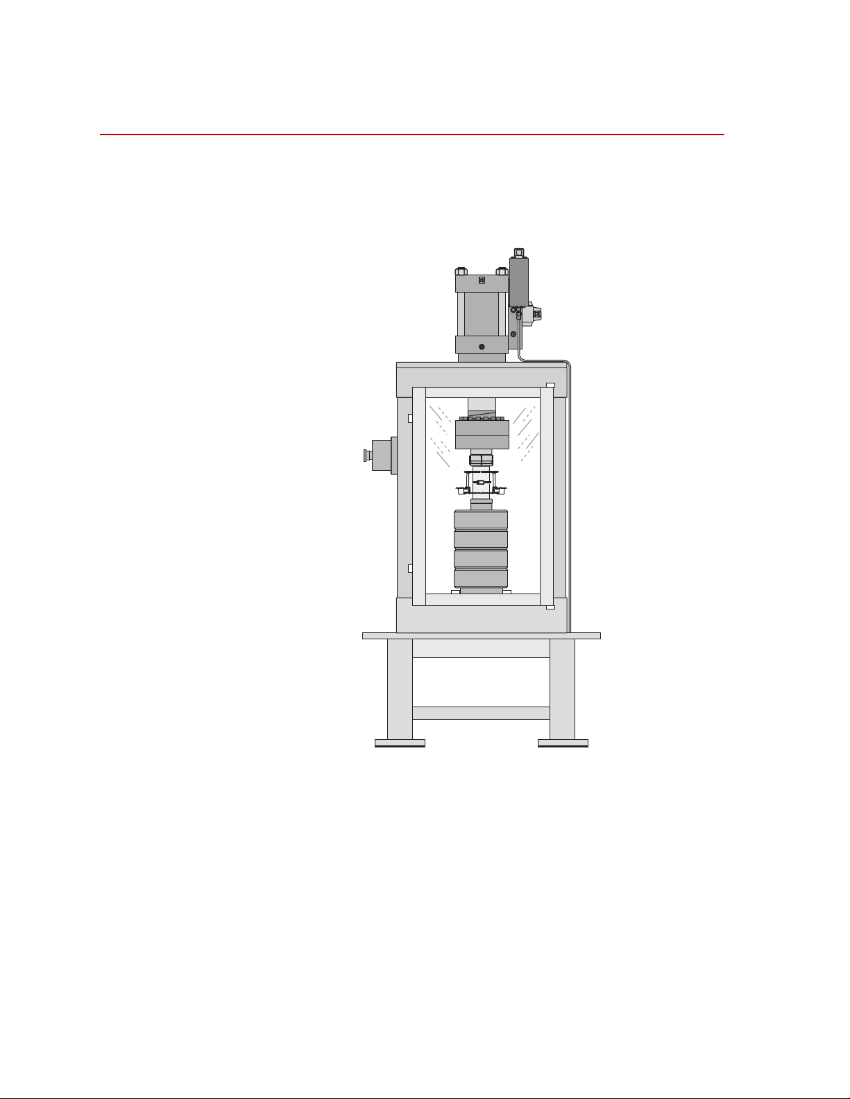
Functional Description
r
Model
632.94
r
Model
632.94
815-316-01_A
Functional Description
Series 316 Load Frames consist of four vertical columns that support a fixed
crosshead and fixed platen. A combination of the number of spacers and the
actuator stroke is used for adjusting the test space height.
6
Introduction
Series316 Load Frame configured for uniaxial compression testing
Series 316 Load Frames have the capability of testing specimens using a triaxial
cell as shown in the following illustration.
Series 316 Load Frame Product Information
Page 7
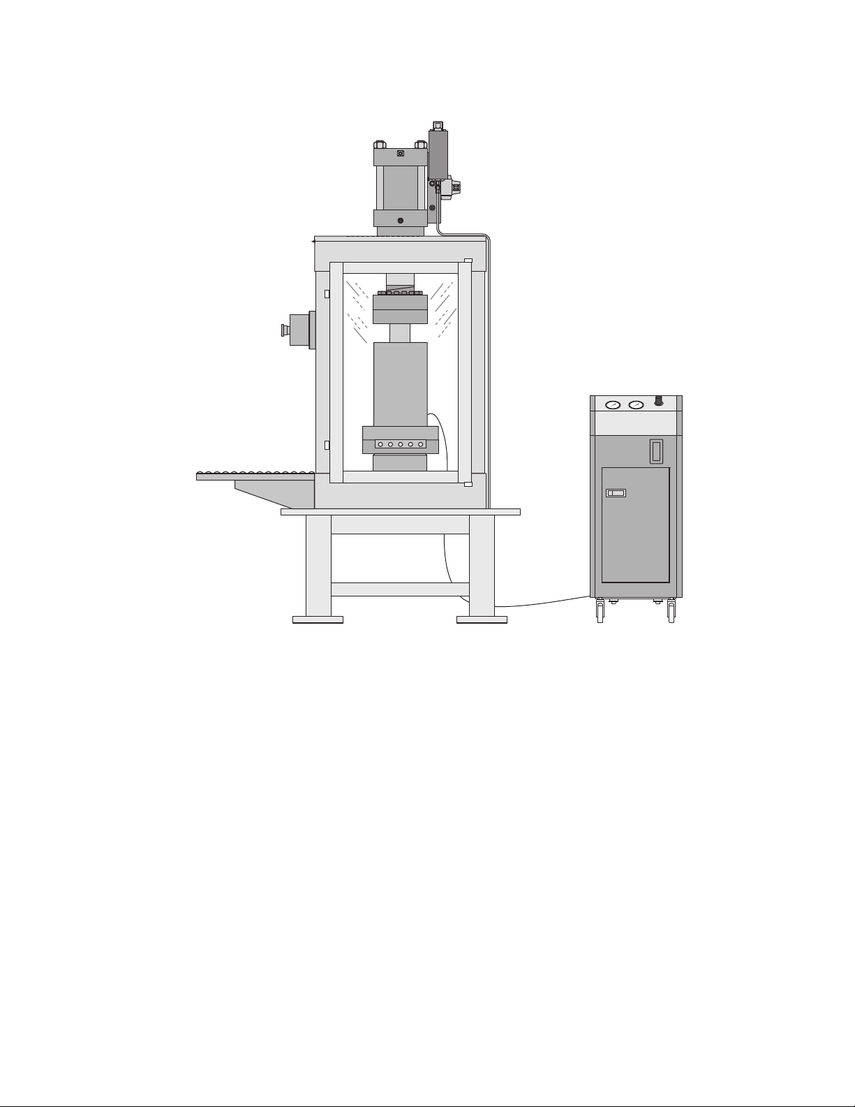
Functional Description
815-316-09
m
Series 316 Load Frame configured for triaxial testing
Series 316 Load Frame Product Information Introduction
7
Page 8
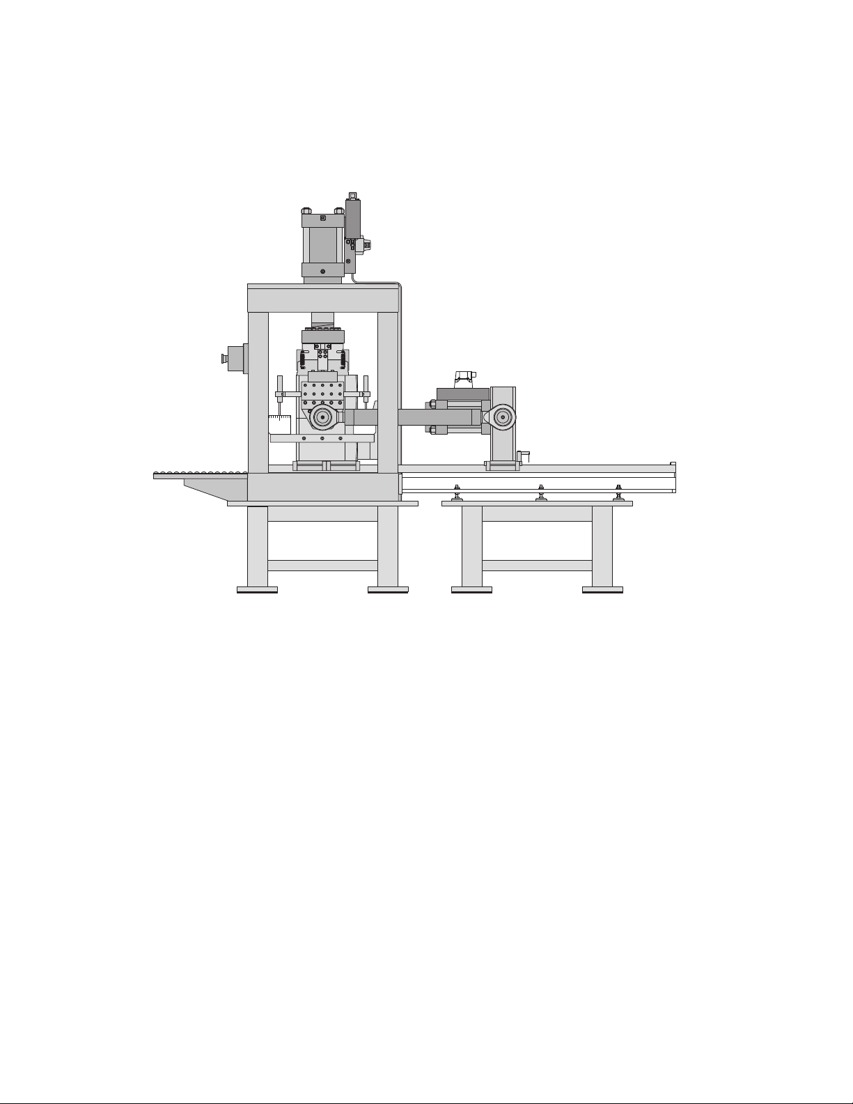
Functional Description
815-316-05
Series 316 Load Frames, when combined with a shear testing assembly, have the
capability of testing specimens in a direct shear mode, as shown in the following
illustration.
Series 316 Load Frame configured for direct shear testing
8
Introduction
Series 316 Load Frame Product Information
Page 9

Specification
Specification
The Series 316 load frames are freestanding and the weight of the frames are
distributed adequately to prevent overload of most laboratory floors. Isolation
pads are provided with the load frames.
This table lists dimensions and weights of the standard 316 Load Frames.
316 Load Frame Specifications (part 1 of 2)
ERIES 316.01 SERIES 316.02 SERIES 316.03 SERIES 316.04
S
Actuator 243.40S 243.60S 243.70S 243.80S
Compression kN(kip) 496(111) 1013(227) 1459(328) 1984(446)
Tension kN(kip) 291(65) 648(145) 961(216) 1334(300)
Actuator Displacement
mm(in)s
Load Frame Spring Rate:
N/m 1.1x10^9 2.6x10^9 2.6x10^9 3.0x10^9
Lb/in 6.2x10^6 1.5x10^7 1.5x10^7 1.7x10^7
Parallel alignment Between
platens
100(4) 100(4) 100(4) 100(4)
0.051(0.002) 0.051(0.002) 0.051(0.002) 0.051(0.002)
Series 316 Load Frame Product Information Introduction
9
Page 10

Specification
316 Load Frame Specifications (Continued) (part 2 of 2)
SERIES 316.01 SERIES 316.02 SERIES 316.03 SERIES 316.04
Force Measurement Load Cell Load Cell ΔP transducer ΔP transducer
Load Frame Height:
(Standard) mm(in) 1523(60) 1653(65) 1733(68) 1765(69)
(Table) mm(in) 609(24) 617(34) 617(34) 617(34)
Test Space mm(in) 736+/-50 (29+/-2) 735+/-50 (29+/-2) 735+/-50 (29+/-2) 730+/-50 (28.75+/-2)
Floor Loading Length mm
(in)
Floor Loading Depth mm (in) 686(27) 762(30) 762(30) 762(30)
Approx. Load Frame Weight
Kg (lbs)
Floor Loading
kg/m2 (psi)
940(37) 1118(44) 1118(44) 1118(44)
2512 (5540) 3266 (7200) 3400 (7500) 3855 (8500)
3895 (5.6) 3834 (5.5) 3991 (5.7) 4525 (6.5)
10
Introduction
Series 316 Load Frame Product Information
Page 11

Direct Shear Capability
Refer to the assembly drawings typically found on teh system reference manual
CD for additional information.
P
ARAMETER SPECIFICATION
Specification
Actuator
Tension kN (lbs) 162 (36.4)
Compression kN (lbs) 254 (57.0)
Actuator Displacement mm (in) 100(4.0)
Force Measurement Load Cell
Specimen Dimension
Diameter mm (in) 150 (5.90)
Length mm (in) 300 (11.82)
Gap mm (in) 20 (0.79)
Floor Loading Length mm (in) 1365(54)
Floor Loading Width mm (in) 760 (30)
Approximate Frame Weight
Kg (lbs) 2425 (1100)
* For additional information, refer to the Series 243 Hydraulic
Actuator Product Information Manual; part number 011774800
243.20
*
Series 316 Load Frame Product Information Introduction
11
Page 12

Specification
12
Introduction
Series 316 Load Frame Product Information
Page 13

Operation
Procedures in this section assume the operator is familiar with all operating
aspects of the system electrical controller and interlock restrictions that apply to
starting the hydraulic power supply.
The operation instructions for the Series 316 Load Frame include specimen
mounting for Uni-axial and Direct Shear configurations. The instructions also
describe insertion of MTS Model 656 Tri-axial cells. Please see the appropriate
Tri-axial instruction manual for specimen preparation and insertion inside the triaxial cell.
Hydraulic Configurations
Series 316 Load Frames are provided with hydraulic service manifolds for
control of hydraulic pressure. Systems configured for direct shear applications
are provided with a Model 293 hydraulic service manifold for control of
hydraulic pressure to the axial and direct shear actuators; refer the the 293.1x
Hydraulic Service Manifold Product Information, part number 015081000, for
additional information.
Hydraulic Configurations
Attached to the return pressure lines is a dump solenoid that will direct returnline hydraulic pressure to the drain line following shutdown. Shutdown without
a dump solenoid would cause the actuators to slowly drift because the actuators
have unequal area pistons.
Series 316 Load Frame Product Information Operation
13
Page 14

Specimen Mounting Considerations
Specimen Mounting Considerations
Specimen mounting is the most critical and potentially hazardous step in system
operation. Improper operation of the load frame during specimen installation or
testing can cause damage to equipment or specimens. Observe the following
precautions when installing a specimen.
• Configure the test program to reduce the possibility of specimen buckling
both during the test and at specimen failure. Buckling can cause damaging
side loads to be applied to the load cell.
• If the specimen will be tested in both tension and compression, reduce
backlash to a minimum. This will reduce the possibility of data being
invalidated by fixture or specimen shifting.
14
Operation
Series 316 Load Frame Product Information
Page 15

Uniaxial Configuration
Shown with crosshead removed
Installation of Hardware
If not already installed, attach the square loading block to the base of the frame.
Uniaxial Configuration
Note Torque the bolts per the specifications on the load frame assembly
drawing for full tension capability of the system. Compression testing
conditions do not require this torque setting. The bolts should however
be tightened to a level to prevent mechanical backlash when conducting
through-zero tests (tension/compression/tension).
Series 316 Load Frame Product Information Operation
15
Page 16

Uniaxial Configuration
Compression Indirect Tension
Installation of spacers as required
Install the appropriate number of spacers for the test to be conducted. When
determining the number of spacers needed, it is best to extend the actuator to a
position that leaves just enough stroke for the expected testing needs. This
actuator position helps reduce the risk of damage to the specimen or fixtures due
to actuator over-travel.
Typical steps for determining load train components:
1. After ensuring that there is adequate clearance, fully extend the actuator.
2. Retract the actuator the estimated distance required for the test.
3. Compare the opening with the sum of the displacement required for the test,
the height of the specimen, and the height of any fixturing required for the
test such as compression platens and adapter plates.
4. Determine the number of spacers required to fill the remaining test space.
By adjusting the actuator position and adding or removing spacers, it will be
possible to obtain the correct test space.
5. Install all components and ensure that all bolts are tightened appropriately.
Operation
16
Series 316 Load Frame Product Information
Page 17

Specimen installation
1. Turn the hydraulic service manifold (HSM) off.
2. Insert the specimen into the test space. Attach extensometers to the
3. Attach any electrical cabling for the load cell and extensometers.
4. Remove the zero pins from the extensometers and zero offset the transducer
5. Close the front door of the load frame. The front door interlock will engage
6. If not already in stroke control, change the actuator control mode to stroke
7. Turn the hydraulic service manifold (HSM) on.
8. Zero the load signal and change the control mode to load control, and apply
Uniaxial Configuration
specimen, with the zero pins in place.
signals. For additional information see the TestStar Operations Manual.
when the door is closed.
control.
a seating load to the specimen.
Note Opening the door will generate a program interlock but will not turn off
the hydraulic service manifold (HSM).
Series 316 Load Frame Product Information Operation
17
Page 18

Uniaxial Configuration
Specimen removal
1. When the test is complete or the specimen is to be removed from the test
space, change the servo control mode to stroke control and retract the
actuator.
2. Turn the hydraulic service manifold (HSM) off.
3. Open the front door of the frame.
4. Remove the extensometers from the specimen, and insert the zero pins. The
zero pins help protect the extensometers from inadvertent over-travel.
5. Remove the specimen.
18
Operation
Series 316 Load Frame Product Information
Page 19

Tri-axial Configuration
Shown with
optional lift
Tri-axial Configuration
316 Load Frame with Closed Triaxial Cell
Installation of Hardware
1. Remove any spacer plates that may have been used in the uniaxial or direct
shear test configurations
2. Remove the uniaxial load cell.
3. Install the square loading plate on the base of the frame if it is not already
installed.
Series 316 Load Frame Product Information Operation
19
Page 20

Tri-axial Configuration
Note Torque the bolts per the specifications on the drawing for full tension
capability of the system. Compression testing conditions do not require
this torque setting. The bolts should however be tightened to a level to
prevent mechanical backlash when conducting through-zero tests
(tension/compression/tension).
4. Install positive stops, quantity 2.
20
Operation
Series 316 Load Frame Product Information
Page 21

5. Install locating block for the triaxial cell.
Tri-axial Configuration
Series 316 Load Frame Product Information Operation
21
Page 22

Tri-axial Configuration
Tri-axial Cell Initial Installation
1. Position the vessel-mounting table on the slides that extend out from the
front of the load frame test space.
22
Operation
Series 316 Load Frame Product Information
Page 23

Tri-axial Configuration
2. The loading bolts should be tightened to hold the bell of the tri-axial cell to
the tri-axial cell base.
3. Using the crane, lift and place the triaxial cell onto the vessel-mounting
table.
4. Disconnect the crane from the tri-axial cell.
Series 316 Load Frame Product Information Operation
23
Page 24

Tri-axial Configuration
Shown with
optional lift
Installation of the specimen into the triaxial cell
Note It is assumed that the actuator has been retracted to allow adequate
room to insert the triaxial cell into the test space.
24
Operation
316 Load Frame with Open Triaxial Cell
1. Use spring loaded retention pins to hold the triaxial cell locating plate to
horizontal slides.
2. Attach the lifting crane to the triaxial cell.
3. Apply a lifting load to the bell of the triaxial cell and lift the bell high
enough to allow for specimen installation.
Note Due to seal pressure, it may be necessary to tap the lower base plate
with a softheaded hammer as the bell is being removed from the base
plate.
4. Install the specimen and any additional hardware such as endcaps,
extensometers, and pore pressure lines. Connect transducers cables to the
mounted connectors inside the triaxial cell.
5. For Ultrasonic testing, specific platens containing the ultrasonic P, S1 and
S2 crystals must be installed. These platens are operated with external
electronics.
Series 316 Load Frame Product Information
Page 25

Tri-axial Configuration
6. After the specimen has been installed and all internal electrical connections
have been made, turn the crane handle counter-clockwise to lower the bell
of the tri-axial cell onto the base plate using the locating pins as guides.
7. Disconnect the crane from the triaxial cell.
8. Connect the tri-axial cell bell to the base plate.
9. Slide the triaxial cell into the test space until it comes to rest against the
positive stops.
10. Attach the locating stop to the base of the frame.
11. Attach confining and pore lines to the triaxial cell as required for the test.
12. Connect all transducer ID and system cables.
Series 316 Load Frame Product Information Operation
25
Page 26

Tri-axial Configuration
13. Close the front door of the load frame.
14. Turn the hydraulic service manifold (HSM) on with the actuator in stroke
control.
15. Switch to load control and extend the actuator so that the actuator touches
the upper pushrod of the triaxial cell.
16. Turn the HSM off.
17. Open the door and attach the pushrod to the actuator rod with bolts.
18. Close the front door and proceed with the test program, which would
include such items as filling the vessel with fluid, bringing pressure system
to desired test parameters and electrically zero all transducers.
Note The door interlock does not turn off the HSM. The switch does provide a
program interlock. See the TestStar manuals for more information about
testing programs that use control hardware interlock.
26
Operation
Series 316 Load Frame Product Information
Page 27

Specimen removal in the triaxial cell configuration
1. When the test is complete, turn the HSM off.
2. Open the door and remove the bolts attaching the triaxial cell pushrod to the
actuator rod.
3. Close the door, turn the HSM on and retract the actuator.
4. Turn the HSM off.
5. Drain the confining fluid out of the triaxial cell.
6. Disconnect the confining and pore pressure lines.
7. Disconnect the transducer ID and system transducer cabling.
8. Remove the locating stop from in front of the triaxial cell.
9. Slide the triaxial cell out along the rails.
10. Use the spring-loaded retention pins to hold the locating plate to the rails.
Tri-axial Configuration
11. Attach the lifting crane to the triaxial cell.
Note To release the lifting cable, it may be necessary to pull on the end while
turning the crank counterclockwise.
12. Apply a lifting load to the bell of the triaxial cell.
Note Seal pressure may require using three jacking screws in the base of the
cell to help the triaxial cell bell separate from the baseplate.
13. Move the bell of the tri-axial cell off to the side and lower it to a safe
position.
14. Remove the specimen.
15. Remove the extensometers from the specimen, and insert the zero pins. The
zero pins help protect the extensometers from inadvertent over-travel.
Series 316 Load Frame Product Information Operation
27
Page 28

Direct Shear Configuration
Direct Shear Configuration
Installation of Hardware
1. Remove any spacer plates that may have been used in the uniaxial and
triaxial configurations.
2. Remove the uniaxial load cell.
3. Install the axial load cell used with the direct shear testing configuration.
Note Use spanner wrenches to preload the mechanical joint.
4. Optional: Remove restraint blocks on the axial spherical seat
5. Remove square loading plate on the base of the frame.
6. Remove the positive blocks, quantity 2, used to for the triaxial test
configuration.
7. Remove locating block for the triaxial cell.
Note It assumed that the actuator has been retracted to a safe position.
28
Operation
Series 316 Load Frame Product Information
Page 29

Installation of the Direct Shear hardware
Note The upper and lower portions of the direct shear specimen box may be
attached with handles. Do not remove the handles until the direct shear
system is installed in the test space and the upper portion of the fixture is
attached to the actuator rod.
1. Remove the locating pin on the direct shear hardware and push the assembly
into test space.
2. Insert the locating pin into the forward locating hole.
3. Close the load frame front door.
4. With the axial actuator in stroke control, turn the HSM on.
5. Position the axial actuator to allow connection of the axial load cell used
with the direct shear configuration.
6. If attached, remove handles supporting the upper portion of the direct shear
assembly.
Direct Shear Configuration
Series 316 Load Frame Product Information Operation
29
Page 30

Direct Shear Configuration
Direct Shear Specimen Preparation
1. Locate the two specimen shear boxes.
2. Place the lower shear box on a clean, flat surface. Use a sealant such as
modeling clay to seal around the inside edges of the box to prevent leakage
of the filler. Typical filler material is Hydro-stone plaster. Hydro-stone uses
a weight mix ratio of 32/100 (water/plaster), or a mixture of 0.326 liters of
water per kilogram of Hydro-stone.
Note Water weighs approximately 0.98 kg/liter (8 lbs/gallon).
3. Place the specimen in the box such that the desired specimen shear plane is
horizontal, and located vertically in the center of the gap between the two
halves of the box. If necessary, support the specimen with a block of wood.
Fill the cavity of the box with the appropriate filler.
Note Large spaces around the specimen may be filled with pieces of filler from
previous tests.
4. Place the specimen box spacers on the corners of the lower shear box.
5. Place the spacer material on top of the lower shear box. For reference, wood
is often used for this material with a nominal thickness of about 25 mm.
This material will have to be cut to accommodate the specimen and
specimen box spacers.
6. Using a sealant such as modeling clay seal the edges of the upper inside
specimen box.
7. Place the upper shear box on top of the box spacers. Attach the front handle
to the upper and lower shear boxes. Once the handle is bolted in place, the
upper and lower shear boxes will be correctly positioned with respect to
each other.
8. Fill the upper shear box with the filler material.
9. Let the filler set. A typical set time is 12 hours.
30
Operation
Series 316 Load Frame Product Information
Page 31

Direct Shear Configuration
Direct Shear Specimen Insertion into the Test Space
Note It is assume that system is in a safe operating condition.
1. Attach the crane to lifting eyes on the upper direct shear box with a lifting
strap.
2. Open the front door of the load frame. Place the nylon spacer on top of the
triaxial cell vessel-mounting table.
3. Using the crane place the direct shear box assembly on the nylon spacer of
the loading plate. Disconnect the crane from the direct shear boxes.
4. Push the direct shear box assembly into the test space.
5. Attach the shear box assembly to the direct shear system with 16 bolts and
torque each bolt to 7.8 N-m (69 in-lbs), alternating between top and bottom
shear box assembly.
6. Remove the front handles.
7. Remove the two bolts from the spherical seat assembly that were used to lift
the upper specimen box.
8. Attach all transducer ID and system cables.
9. Adjust the six displacement transducers into positions that are close to the
electrical null of the transducer output.
10. Remove any remaining electrical offsets with the controller.
11. Close the front door of the load frame.
12. Change the control mode so that the direct shear actuator is in stroke control
and the axial actuator is in load control.
13. Remove any servo error in the system and turn the system axial and direct
shear HSM on.
14. Proceed with testing.
Note Opening the door will generate a program interlock but not turn off the
HSM.
Series 316 Load Frame Product Information Operation
31
Page 32

Direct Shear Configuration
Direct Shear Specimen Removal from Test Space
1. Change control modes so that the axial and direct shear actuators are in
stroke control.
2. Attach the upper specimen box to the spherical seat using two lifting bolts.
3. Using the axial actuator, position the specimen boxes appropriately to attach
the front handles to the specimen boxes, and attach the front handles.
4. Turn the axial and direct shear HSM off.
5. Open the front door of the load frame.
6. Disconnect the shear box from the direct shear assembly by loosening and
removing the 16 bolts that hold the specimen to the shear assembly.
7. Slide the assembly onto the carriage and remove it from the test space. Use
the crane assembly with lifting eyes and a strap to move the specimen box
assembly.
32
Operation
Series 316 Load Frame Product Information
Page 33

Test specimen removal from specimen box
Removing grout (filler) material from the specimen boxes using a mallet to break
up the grout. Some disassembly of the specimen box may be required to remove
all the grout.
Direct Shear Configuration
Series 316 Load Frame Product Information Operation
33
Page 34

Direct Shear Configuration
34
Operation
Series 316 Load Frame Product Information
Page 35

Maintenance
Making Daily Inspections
Before the start of each day’s testing, do a quick inspection of your load frame.
Following are typical items that should be checked daily:
• Ensure that there are no leaks from the hydraulic lifts or locks.
• Ensure that there are no leaks from the actuator, hydraulic service manifold,
servovalve, or accumulators.
• Ensure that electrical connections are tight, with no frayed or poorly routed
cables.
• Ensure that hoses are routed properly and that fittings are not leaking.
Making Daily Inspections
Series 316 Load Frame Product Information Maintenance
35
Page 36

Preventing Rust
Preventing Rust
The operating environment determines how often you take rust prevention
measures. Humid and corrosive environments require more prevention.
Recommended supplies:
• #1 grade kerosene
• Silicone spray
• 000 emery cloth
• Touchup paint; MTS part numbers 011-059-854 (beige), 011-059-856
• Metal primer paint
• Lint-free cloths
Unpainted surfaces: Spray with silicone, and then wipe with a clean, lint-free
cloth. Or, wipe with a clean, lint-free cloth dampened with clean hydraulic fluid.
(gray), 044-587-501 (brown)
The direct shear specimen boxes should be protected with a rust inhibitor when
not in use.
Chrome plated surfaces: For microscratches, wipe with a clean, lint-free cloth
dampened with #1 kerosene. For rust discoloration, polish with 000 emery cloth,
and then wipe down. Black oxide surfaces: Spray with silicone, and then wipe
with a clean, lint-free cloth. Or, wipe with a clean, lint-free cloth dampened with
clean hydraulic fluid. Painted surfaces: For small scratches, use touchup paint.
For large scratches, sand, prime, and use touchup paint.
36
Maintenance
Series 316 Load Frame Product Information
Page 37

Checking the Accumulators’ Precharge Pressures
Checking the Accumulators’ Precharge Pressures
Check pressure at least once a month; more often as required by operating
conditions. An accumulators’ correct precharge pressure is written on its label.
See the Series 111 Accumulator Product Information manual (part number
011553304) for the complete details on checking the precharge intervals and
servicing the accumulators. Record both the pressures and the room temperature
in a logbook. Use these readings as a basis for increasing or decreasing the
interval between pressure checks. Generally, recharging is required when there is
a change of ±1.4 MPa (200 psi) in the pressure line accumulator or ±50% in the
return line accumulator.
Series 316 Load Frame Product Information Maintenance
37
Page 38

Servicing the Actuator
WARNING
Servicing the Actuator
If the actuator begins leaking hydraulic fluid or its performance becomes poor, it
should be serviced by a qualified service technician.
The hydraulic blocking valves will cause system pressure to be trapped in
actuator that can cause unexpected actuator rod movement.
Unexpected actuator rod movement can result in personal injury and
equipment damage.
There is a pressure relief control on the actuator manifold that allows this pressure
to be dissipated.
38
Maintenance
Series 316 Load Frame Product Information
Page 39

Installation
This section provides installation instructions for Series 316 Load Frame. MTS
System Corporation recommends that the procedures in the following
subsections be performed in the order given or referenced to minimize the chance
of damage to equipment or injury to personnel.
Unpacking and Inspection
Unpacking and Inspection
Unpacking Load
Frame
Unpacking Direct
Shear
Inspection Inspect the load frame for evidence of structural damage. Inspect any electrical
If the load frame is shipped in the horizontal position strapped to a wooden skid,
it should be uncrated and tipped to its upright position before it is moved. Use
the following procedure:
1. Carefully cut and remove the strap form around the load frame using an
appropriate tool. Some load frames are bolted to the skid. Remove these
bolts if applicable.
2. Series 316 load Frames are shipped with eye bolts installed in the holes in
the top of the crosshead.
A. Attach lifting chain hooks (or equivalent) to all lift point eyebolts or
hoist rings. Ensure chain hooks are secure and of sufficient capacity
for the task (see “Specification” on page 9 for the weight of frame.)
B. Block the bottom of the load frame to prevent slipping as the load
frame is raised.
C. Slowly lift load frame to vertical position.
1. Remove direct shear assembly with guide rails from crate.
2. Carefully cut and remove holding straps to direct shear assembly.
connectors mounted on the load frame base for damage and cleanliness. If
shipped with hydraulic hoses attached, inspect the hose for evidence of damage
and leakage. Inspect the hose connections fitting for damage.
Series 316 Load Frame Product Information Installation
39
Page 40

Lifting and Moving Instructions
WARNING
Lifting and Moving Instructions
This subsection provides a procedure for lifting and moving the load frame.
Improper lifting or transportation of the device can result in damage to
equipment or injury to personnel.
Read and comply with the following instructions and refer to the Lifting and
Moving Instructions booklet attached to the load frame.
1. Ensure all devices involved in lifting and moving the load frame are in good
working order. Inspect eyebolts or hoist rings, chains, overhead crane, etc,
for cracks and damage. Replace as necessary.
2. Ensure all devices involved in lifting and moving the load frame can support
the weight of the load frame. (This weigh includes the load frame, load cell,
actuator, servo valve(s), manifold(s) grips, etc.)
3. The load frame must be lifted at the designated lift points only. The lift
points are locate on top of the crosshead.
4. If chains will be used to lift and move the load frame, the lifting chains must
not exceed a 30-degree angle from vertical to prevent undesired stress/strain
on the eyebolts or hoist rings.
5. Do not apply shock loads when lifting or moving the load frame. Shock
loads can cause momentary forces exceeding the actual load frame weight,
which can result in exceeding the recommended force rating of the lifting
devices.
6. Before lifting or moving the load frame, ensure all lifting chain hooks (or
equivalent are securely placed in all lift point eyebolts or hoist rings.
7. Lift load frame only has high as necessary. It is recommended to lift the
load frame only a few inches off the ground.
8. Move load frame to desire location and carefully lower into position
40
Installation
Series 316 Load Frame Product Information
Page 41

Installation of Load Frame
1. Move the load frame to the desired location.
Location requirements of the load frame are based primarily upon size,
weight, and hydraulic requirements. Floor structure should be checked to
ensure that the weigh of the load frame could be supported. Ensure safe
and adequate access space in all directions around the load frame. Ensure
safe and adequate lighting. Adequate and appropriate routing of control
cables and hoses should be located, playing special attention to conditions,
which can cause cable or hose damage.
2. Level the load frame.
If it is necessary to level the load frame, one or more pieces of shim stock
can be placed under one or more of the feet. This operation should be done
in conjunction with the vibration pad installation( see atep 3).
3. Install vibration isolation pads.
Most load frames are supplied with rubber vibration isolation pads that
absorb some of the vibration of the load frame, protecting the support floor.
These pads must be stacked, separated by metal dividers, and installed under
the four corners of the load frame.
Installation of Load Frame
4. Install direct shear fixture.
A. Position the direct shear fixture base at the rear of the 316-load frame.
B. Place isolation pads under direct shear base. If necessary metal shims
may be used.
C. Attach bolts that attach direct shear base to rear of load frame base.
Note Direct Shear fixture can slide without proper support. Do not allow direct
shear fixture to slide off guide rails.
D. Align guide rails to mounting hole pattern on base of load frame.
E. Adjust feet of direct shear fixture.
F. Attach guide rails to load frame base.
5. Install 293.11 Service Manifold.
The service manifold does not require isolation pad. It may be located in a
convenient spot within reach of system hoses.
6. Install hydraulic hoses and electrical connections.
A. Connect all applicable hydraulic hoes and all electric cables.
B. Typical hose connections to load frame consist of –6 pressure, -6 return
and –6 drain. Care should be observed that appropriate hose
connections are made.
C. Typical hose connections to direct shear assembly consist of –4
pressure, -4 return and –4 drain.
Series 316 Load Frame Product Information Installation
41
Page 42

Installation of Load Frame
42
Installation
Series 316 Load Frame Product Information
Page 43

Page 44

m
MTS Systems Corporation
14000 Technology Drive
Eden Prairie, Minnesota 55344-2290 USA
Toll Free Phone: 800-328-2255
(within the U.S. or Canada)
Phone: 952-937-4000
(outside the U.S. or Canada)
Fax: 952-937-4515
E-mail: info@mts.com
http://www.mts.com
ISO 9001:2000 Certified QMS
 Loading...