

Page 1

Series 315 Load Frame
Product Information Manual
Model 315.01
Model 315.02
Model 315.03
Model 315.04
l
100-104-403 A
Page 2

Copyright information © 2002 MTS Systems Corporation. All rights reserved.
Trademark information MTS is a registered trademark of MTS Systems Corporation.
Contact information MTS Systems Corporation
14000 Technology Drive
Eden Prairie, Minnesota 55344-2290 USA
Toll Free Phone: 800-328-2255 (within the U.S. or Canada)
Phone: 952-937-4000 (outside the U.S. or Canada)
Fax: 952-937-4515
E-mail: info@mts.com
http://www.mts.com
Publication information
Manual Part Number Publication Date
100-104-403 A
November 2002
Page 3

Contents
Introduction 5
Component Identification 7
Functional Description 8
Specifications 10
Load Frame Dimensions 11
Floor Loading Footprint Dimensions 13
Load Frame Stiffness Calculation 14
Installation 17
Lifting and Moving Instructions 18
Connecting Cables 23
Connecting Hydraulics 24
Operation 25
Emergency Stop 25
Crush Point Hazards 26
Maintenance 27
Maintenance Intervals 28
Making Daily Inspections 29
Minimizing Rust 30
Methods for Various Surfaces 30
Checking the Accumulators’ Precharge 31
Series 315 Load Frame Contents
3
Page 4

4
Contents
Series 315 Load Frame
Page 5
Introduction
Contents Component Identification 7
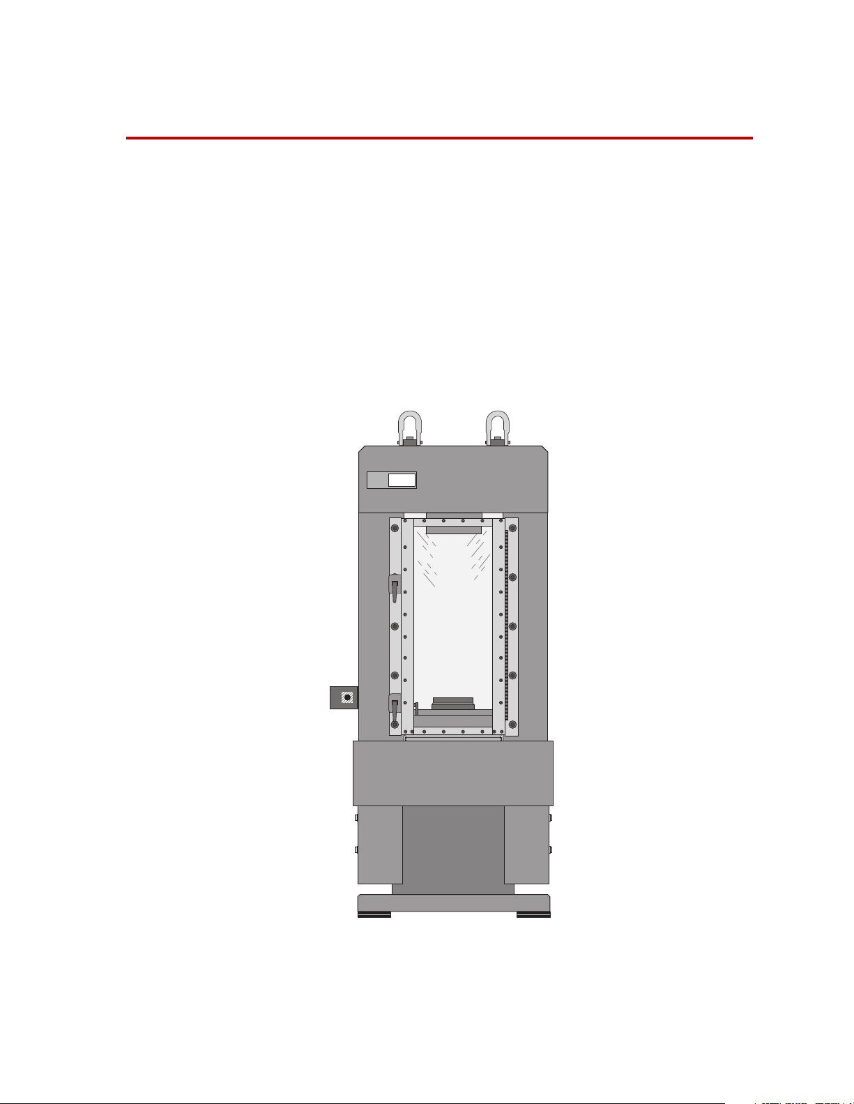
The Series 315 Load Frames are designed to perform high-velocity tension
or compression testing, high-frequency fatigue testing, as well as other
tests. The load frame must be configured with optional actuators,
servovalves, force transducers, grips, and other components from MTS
Systems Corporation.
Functional Description 8
Specifications 10
“Load Frame Stiffness Calculation” on page 14
815
Rock Mechanics
r
Test System
Series 315 Load Frame Introduction
5
Page 6

What you
need to know
This manual assumes that you know how to use your system controller.
See the appropriate manual for information about performing any
controller-related step in this manual’s procedures. You are expected to
know how to do the following:
• Turn system electrical power on and off
• Turn hydraulic pressure on and off
• Manually adjust the actuator position
• Use your grips and fixtures
Related products The load frame includes other products. See the following product manuals
for product-specific information and maintenance procedures.
• The Series 111 Accumulator Product Information manual.
(part number 011-553-300)
• The Series 252 Servovalve Product Information manual
(part number 011-182-900)
• The Series 298 Actuator Manifold Product Information manual
(part number 011-563-103)
6
Introduction
Series 315 Load Frame
Page 7
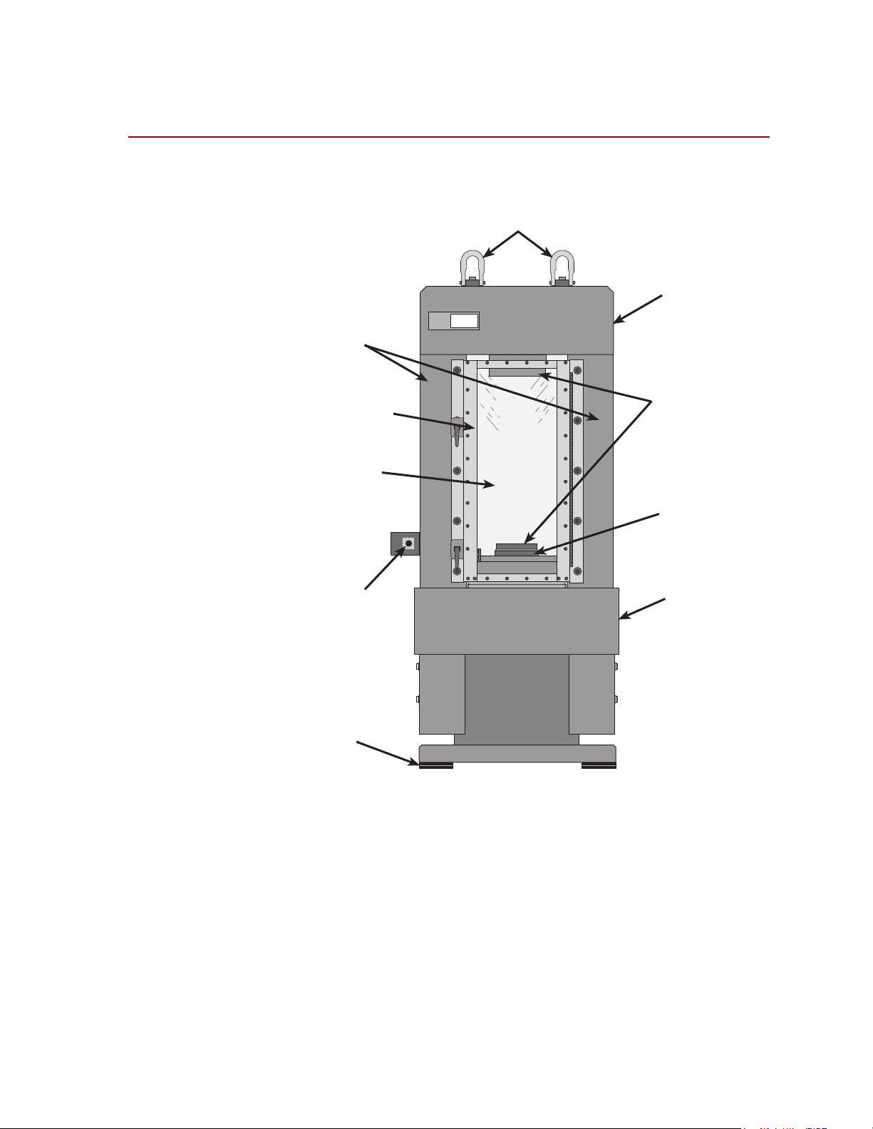
Component Identification
Retangular
Columns
Security
Door
Impact Resistant
Lexan Panel
r
Rock Mechanics
Test System
815
Hoist Rings
Rigid Fixed
Crosshead
Accessory
Attachment
Plates
Fatigue Rated,
Single-ended,
Double-acting
Actuator
Emergency Stop
Button
Vibration
Isolation Pads
Stiff Base
Plate
Series 315 Load Frame Introduction
7
Page 8

Functional Description
The load frame is a stand alone testing structure. The following paragraphs
describe the components shown on the illustration in the “Component
Identification” on page 7.
Load Frame The load frame has an integrated construction that provides high stiffness,
reducing deflection energy stored in the frame — ideal for testing brittle
materials. The actuator is integrated into the base plate which decreases
frame height and increases stiffness.
The integrated construction also provides a precision, parallel alignment
between crosshead and actuator surface for proper specimen loading.
The load frame provides a large test area for uniaxial and triaxial testing.
The front security door allows easy access to test space. The impact
resistant Lexan panels in front and back allow observation of tests in
progress and helps contain specimen fragments.
Actuator The actuator is a single ended, double acting design allows testing in
compression and tension. The actuator provides a 100 mm (4 in) actuator
stroke for tests requiring large displacements.
Proprietary seal and bearing designs, which have set an industry standard
for durability, ensure long life and performance. Direct-bonded polymer
bearings reduce friction and maximize heat dissipation.
Transducers The load frame usually includes a force transducer and an LVDT (or other
Differential Pressure
∆P) Transducer
(
Internal Linear Variable
Differential Transformer
(LVDT)
displacement measurement device.
The ∆P transducer provides force readout without affecting load frame
stiffness. The ∆P transducer is accurate to within ±1% of the calibrated
range at loads above 1000kN. It provides useful measure of external loads
applied to specimens inside a triaxial cell, when conducting multiple
failure state tests per ISRM. The output signal is conditioned at the Digital
Controller for closed-loop control and data acquisition.
The LVDT is calibrated to full scale actuator travel to provide complete
positioning control. The LVDT is used for specimen positioning and
preloading, and measuring actuator displacement during the test. The
output signal is conditioned at the Digital Controller for closed-loop control
and data acquisition.
8
Introduction
Series 315 Load Frame
Page 9

Servovalves Servovalves regulate the direction and flow of the hydraulic fluid to and from a
hydraulic actuator. The servovalve responds to the polarity and magnitude of the
command signal generated by the controller.
Hydraulic distribution Hydraulic distribution includes a hydraulic manifold (also called an actuator
manifold or hydraulic service manifold) which controls the hydraulic pressure to the
load frame. The manifold includes solenoid valves that control the hydraulic
pressure (off, low, or high). An actuator manifold is mounted directly to the actuator
on the load frame. A hydraulic service manifold (HSM) is located near the load
frame and connects to the actuator with hydraulic hoses.
Most hydraulic distribution systems will also include a check valve in the return line.
The purpose of this check valve is to minimize actuator drift where pressure is
present on the return line without servo control of the 315 frame.
Series 315 Load Frame Introduction
9
Page 10

Specifications
Compression rating
kN 1600 2700 4600 4600
kip 350 600 1000 1000
Model 315.01 Model 315.02 Model 315.03 Model 315.04
Tension rating
*
kN 1050 1350 2300 2300
kip 240 300 500 500
Actuator displacement
mm 100 100 100 100
in 4444
Load frame spring rate
†
N/m
lb/in
Parallel alignment between
platens
mm 0.051 0.051 0.051 0.051
in 0.002 0.002 0.002 0.002
Weight
kg 2359 3855 6350 7590
lb 5200 8500 14,000 16,700
7. 0 x 10
4.0 x 10
9
7
9.0 x 10
5.0 x 10
9
7
11.0 x 10
6.3 x 10
9
7
10.5 x 10
6.0 x 10
9
7
Floor Load (using four102 x
152 mm (4 x 6 in.) vibration
isolation pads)
‡
kPa 380 614 1007 1200
psi 55 89 146 174
* Although the Load Frame assembly is capable of producing the indicated force in tension, the actual
tensile force limit is dependent on the attachment hardware (e.g., threaded connectors) that attach
the gripping fixtures to the crosshead and actuator.
† See “Load Frame Stiffness Calculation” on page 14 for the method used to determine load frame
spring rate.
‡ See the figure and table below for the floor loading footprint dimensions.
10
Introduction
Series 315 Load Frame
Page 11
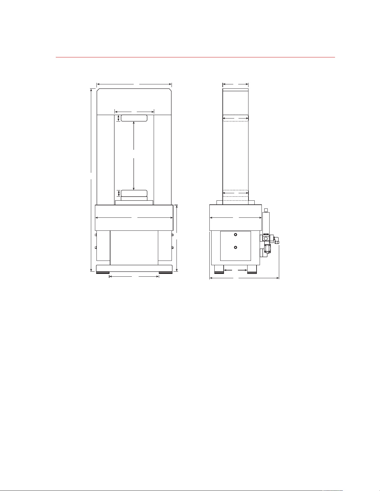
Load Frame Dimensions
D
E
H
J
L
G
A
L
J
B
C
F
M
Model 315 Load Frame Dimensions
N
K
815-315-02
Series 315 Load Frame Introduction
11
Page 12

Model 315.01 Model 315.02 Model 315.03 Model 315.04
*
Dimensions
A 2184 86 2337 92 2692 106 2972 117
B 711 28 914 36 1016 40 1143 45
C 483 19 610 24 737 29 737 29
D 686 27 864 34 953 37.5 1143 45
E 305 12 305 12 356 14 356 14
F 635 25 787 31 965 38 1041 41
mm in mm in mm in mm in
†
G
868 min
970 max
34.2 min
38.2 max
868 min
970 max
34.2 min
38.2 max
868 min
970 max
34.2 min
38.2 max
1160 min
1262 max
45.7 min
49.7 max
H 457 18 457 18 546 21.5 686 27
‡
J
191 7.5 305 12 381 15 381 15
K 640 25.2 805 31.7 927 36.5 927 36.5
L 74 2.94 74 2.94 74 2.94 74 2.94
M 432 17 483 19 584 23 584 23
N 229 9 312 12.3 406 16 406 16
Weight of each
18 kg 40 lb 43 kg 95 lb 68 kg 150 lb 68 kg 150 lb
accessory
attachment
plate (L)
§
* Refer to the figure below for dimension locations.
† The minimum dimension is with the actuator rod fully extended; the maximum dimension is with the
actuator rod fully retracted.
‡ This dimension applies to the piston rod and the accessory attachment plates for the piston rod and
crosshead.
§ Both accessory attachment plates must be removed to use a Model 656 Triaxial Cell in the load frame.
12
Introduction
Series 315 Load Frame
Page 13

Floor Loading Footprint Dimensions
Model
315.01
Length 737 mm
29 in
Depth 432 mm
17 in
Model
315.02
889 mm
35 in
521 mm
20.5 in.
Vibration Isolation
Pads
Length
Model
315.03
991 mm
39 in
610 mm
24 in
102 mm
(4 in)
Model
315.04
991 mm
39 in
610 mm
24 in
152 mm
(6 in)
Depth
815-315-08
Series 315 Load Frame Introduction
13
Page 14

Load Frame Stiffness Calculation
The Load Frame Spring Rate (stiffness) value reported by MTS is a combination of
the theoretical stiffness of the top plate (crosshead), columns and baseplate. The
equations that are used to calculate these numbers are presented below.
Top Plate
Columns
Base Plate
Spring Model
(T)
(C)
(B)
W
H
T
T
D
T
Top Plate
Columns
W
C
H
C
W
H
B
B
D
C
D
B
Base Plate
815-315-09
Definition of Terms A = Area
Introduction
14
D = Depth
E = Modulus of Elasticity
G = Modulus of Rigidity
H = Height
I = Moment of Inertia
K = Spring Rate
L = Length
W = Width
Series 315 Load Frame
Page 15

Top Plate
-
--
ACE
I
T
DTHT)3(
----------------------
=
12
Columns
Base Plate
Spring rate
LTWT2W
ATDTH
ACWCD
–=
=
T
=
C
LCHC=
DBHB)3(
----------------------
I
=
B
LBWT2W
ABHBD
K
K
C
12
–=
=
B
48EI
---------------
=
T
L
T
-----------
=
L
C
C
C
1–
20ATG
T
------------------
+
3
(for each column)
6L
1– 1–
T
K
B
K
System
48EI
--------------- -
=
1–
20ABG
B
------------------ -
+
3
L
B
K
1–
++[=
T
6L
2KC()1–K
1– 1–
B
1–
1–
]
B
Series 315 Load Frame Introduction
15
Page 16

Note to spring rate
equations
Although the baseplate is modeled as a solid rectangular beam, it actually has a large
hole through it where the actuator is mounted. It is assumed, however, that since the
actuator is attached to the baseplate with fully preloaded fasteners, the stiffness of
the baseplate/actuator assembly is approximately comparable to a solid baseplate
(i.e. with no hole through it). The calculated spring rate values have been found to
be in good agreement with actual measurements on load frame assemblies.
The intent in reporting a spring rate value is to allow comparison between load
frames. For this reason, other, more variable elements in the load train, such as
compression platens, force transducers (load cells) and spacers, are not taken into
consideration. (Typically, different components are used for each application
configuration. Including these elements in the calculation would make direct
comparison between frames difficult.)
Since a servo-hydraulic actuator assembly is a dynamically controlled device that
displays a complex effective “spring rate” (based on oil pressure, oil volume,
cylinder deflection, etc.), it is also not included in the calculation. In general, a high
response servo-hydraulic, closed-loop control system in conjunction with a load
frame properly designed for high stiffness, is sufficient to actively control the
actuator, absorb elastic energy stored in the load frame, and prevent loading system
induced specimen failure. Appendix B discusses in more detail the influence of load
frame stiffness on specimen failure behavior.
16
Introduction
Series 315 Load Frame
Page 17

Installation
Contents Lifting and Moving Instructions 18
Prerequisite You will need a fork lift or overhead crane capable of lifting the load
This section describes how to install the Series 315 Load Frame.
Connecting Cables 23
Connecting Hydraulics 24
frame. Ensure the lifting equipment can accommodate the weight of the
load frame, see the following table.
315 Load Frame Weights
Model Weight
315.01 2359 kg (5200 lb)
315.02 3855 kg (8500 lb)
315.03 6350 kg (14,000 lb)
315.04 7590 kg (16,700 lb)
Procedure Perform the following to install the load frame.
1. Unpack the load frame. Go to “Lifting and moving” on page 19 to unpack and
move the load frame.
2. Connect the cables between the load frame and controller. Go to “Connecting
Cables” on page 23 to make the various controller connections. Return to this
procedure when done.
3. Connect the hydraulic hoses between the load frame and hydraulic
service manifold. Go to “Connecting Hydraulics” on page 24 to connect the
load frame to your hydraulic supply system. Return to this procedure when
done.
Series 315 Load Frame Installation
17
Page 18

Lifting and Moving Instructions
Required equipment The load frame is shipped horizontally on a wooden pallet. You will need
the following equipment to unpack the load frame:
• Lifting slings—not chains—to lift the load frame from its pallet
• Lifting chains to tip the load frame upright
• Rubber mats for the load frame’s feet to rest on
• Wooden blocks for the load frame’s columns to rest on
• A knife to cut the packing straps
WARNING
The load frame is extremely heavy.
The weight of the load frame can seriously hurt you and damage your load
frame.
• Do not allow the load frame to drop or topple.
• Ensure that your chains, slings, and crane have a working capacity greater
than the load frame’s weight (see “315 Load Frame Weights” on page 17).
• Ensure that the lifting eyebolts are tight.
• Ensure that the crosshead locking bolts are fully tightened.
• Lift the load frame only high enough to clear its pallet.
• Operate the crane smoothly to prevent sudden shocks to the sling.
Precautions Read and observe the following precautions when moving this load frame.
1. The loaf frame must be lifted at designated lift points. Lift points are
located at the top of the load frame and are noted by placards similar to the
one shown here:
18
Installation
LIFT POINT
2. Ensure all devices involved in lifting and moving the load frame are in
good repair and working order. Repair or replace any hoist rings,
chains, hooks, lifting device, etc., that might be cracked or damaged.
Ensure the hoist rings are properly mounted in the load frame and
properly secured.
Series 315 Load Frame
Page 19

3. Ensure that the device(s) use for lifting and moving the load frame can
support the entire weight shown on the Lifting and Moving Caution placard on
the back of the load frame. This weight includes the load frame, load cell (if
applicable), actuator, servovalve(s), hydraulic service manifold, grips, and any
other devices attached to the load frame as delivered.
4. Do not apply shock loads to the lifting device(s) when lifting or
moving the load frame. Shock loads can cause momentary forces that
exceed the actual load frame weight. Such shock loads can exceed the
recommended lift capacity of the lifting device(s).
5. Before lifting the load frame, ensure that lifting chain hooks (or equivalent
devices) are securely placed in both hoist rings.
6. Lift the load frame only as high as necessary to clear fixed
obstructions.
7. If chains are used to lift the load frame, the lifting chains should not exceed a
30
° angle from vertical. Angles exceeding 30° can cause undesirable stress/
strain on the hoist rings. This restriction applies only when the total weight of
the load frame is to be supported.
Lifting and moving 1. Unpack the load frame from its shipping container.
Remove all devices (straps, bolts, etc.) that secure the load frame to
the shipping skid or crate. If the load frame was shipped in the
horizontal position, remove all crating material down to the base skid.
2. Inspect the load frame for shipping damage.
Look for the following:
• Scratches in the load frame or columns
• Damaged electrical connections
• Damaged hydraulic connections
• Dents and other structural damage
• Torn, kinked, or breaking hoses
Report any damage found to both the carrier and MTS. In the U.S. and
Canada, call the MTS HELPLine at 1-800-328-2255. Elsewhere, contact
your local MTS office.
Note Steps 3 through 5 of this procedure apply only to load frames shipped in
the horizontal position. If the load frame was shipped in a vertical
position, skip to Step 6.
Series 315 Load Frame Installation
19
Page 20

3. Attach lifting device(s).
A. Attach lifting chain hooks (or equivalent devices) to the hoist
rings on top of the load frame. When attaching both hoist rings to
the same point, do not exceed a 30° chain angle as shown in the
following figure. Exceeding a 30° chain angle causes undesired
stress or strain on the eye bolts or hoist rings.
30° Maximum
B. Remove the side covers from the actuator.
C. Attach lift straps around the ends of the upper leg as shown in the
following illustration.
Hoist Ring
D. Connect the slings to a second, separate lifting device.
E. Ensure the attachment devices are secure.
Side Cover
Load Frame Upper Leg
Lift Strap
Side Cover
Supports
Actuator
Lower Leg
20
Installation
Series 315 Load Frame
Page 21

4. Lift the load frame and prepare for vertical positioning.
A. Lift the load frame, keeping it horizontal, until it is completely
clear of the skid and supports.
B. Remove the skid and supports.
C. Place wood beams beneath the bottom (actuator) end of the load
frame, with the length of the beams running parallel to the length
of the load frame.
5. Raise the load frame to its vertical (upright) position.
A. Lower the bottom end of the load frame until it contacts the wood
beams.
B. Block the beams so they do not slide.
C. Slowly raise the load frame to a vertical position. As the unit rises,
keep moving the crane to keep the chains as straight as possible.
D. Disconnect the lift straps from the bottom end of the load frame.
6. Move the load frame to its final location.
Before you move the load frame review the following:
• The floor where the load frame will sit can bear its weight (see “315 Load
Frame Weights” on page 17).
• The path to the load frame’s destination is clear and uncluttered.
• The area where the load frame will sit is clean and well lit, with
all hoses and cables moved out of harm’s way.
A. When the load frame is upright, raise it slightly to clear the wood
beams. Lift the load frame only as high as necessary.
B. Move the load frame slowly to its installation site.
Series 315 Load Frame Installation
21
Page 22

7. Place the load frame onto the isolation pads.
Install stock metal shims between the pads and the floor.
Load Frame
Install
Shims
to Level
Floor
Isolation Pads
C. Lower the load frame gently into place.
D. Replace the actuator side covers.
8. Remove the chains.
22
Installation
Series 315 Load Frame
Page 23

Connecting Cables
Your controller manual should have cabling information about the
connections described in this section. Most controller manuals provide the
signal pinouts of the connector and assembly numbers for standard MTS
cables.
Note Many of the cables are connected to optional equipment. The following
Prerequisite You must have either a cable assembly drawing of your test system, or you must
know the system controller well enough to determine each type of cable connection.
paragraphs list the most common connections. The exact connector
locations vary quite a bit among the various models of the load frame.
Typical cable
connections
• The force transducer is connected to a DC conditioner in the controller.
• The ground connection is located on the back of the control panel. This is
usually connected to a chassis ground on a console or the controller chassis.
• The load frame control panel is connected to the controller chassis. It contains
the emergency stop signal.
• The servovalve is connected to a valve driver in the controller.
• The displacement sensor (also called an linear variable displacement transducer
or LVDT) is connected to an AC conditioner in the controller.
Series 315 Load Frame Installation
23
Page 24

Connecting Hydraulics
The procedure describes how to connect the load frame to the hydraulic
power source. The load frame can be connected directly to the hydraulic
power unit (also called HPU), to hydraulic plumbing in the workplace, or
through a hydraulic service manifold (HSM).
Note The internal hydraulic connections from the actuator manifold and
accessories such as the hydraulic lifts and locks should already be made.
The load frame actuator usually has a manifold mounted to it. The
manifold connects the ports on each end cap to the ports for a servovalve.
The hydraulic connection are made at this manifold.
1. Connect the return line from the hydraulic power source to the
hydraulic port on the manifold labeled “R”.
2. Connect the pressure line from the hydraulic power source to the
hydraulic port on the manifold labeled “P”.
3. Connect the drain line from the hydraulic power source to the
hydraulic port on the manifold labeled “D”.
4. Turn on the HPU and check for any hydraulic pressure leaks.
5. Select low pressure for the load frame and check for hydraulic leaks in
the load frame.
6. Select high pressure for the load frame and check for hydraulic leaks
in the load frame.
7. Return to the installation procedure.
24
Installation
Series 315 Load Frame
Page 25

Operation
This section describes how to use the Series 315 Load Frame.
Contents Emergency Stop 25
Crush Point Hazards 26
Emergency Stop
Emergency Stop The Emergency Stop button shuts down the hydraulic pressure and stops
the test program. Press this button to shut down hydraulic power, and twist
the switch clockwise to release it. Use the Emergency Stop button to shut
down your test if something unexpected should happen.
815
Rock Mechanics
r
Test System
Emergency Stop
Button
Series 315 Load Frame Operation
25
Page 26

Crush Point Hazards
It is important to stay clear of any potential crush points when the system is
operating. You should know where the crush points are in your system
and protect yourself and others from those crush points with appropriate
safety devices. The following paragraphs describe crush points and
precautions to take while working around crush points.
Crush point
Crush points
Locations A crush point exists between the platen and crosshead on load frames
where the actuator piston rod and specimen move (both areas are shown).
Another potential crush point exists where the lower end of the actuator
piston rod extends below the platen and the bottom of the load frame/load
frame.
Precautions Keep clear of any mechanical linkage that moves within a closed area. If
the linkage should move (when the system starts or due to mechanical
failure), very high forces can be present that could pinch, cut, or crush
anything in the path of linkage movement.
26
Operation
Never allow any part of your body to enter the path of machine movement
or to touch moving machinery, linkages, hoses, cables, specimens, etc.
These present serious crush points or pinch points.
Series 315 Load Frame
Page 27

Maintenance
This section describes the procedures which must be periodically performed to
ensure the continued safe and effective operation of your load frame. The
maintenance interval table on page 28 shows a schedule to maintain your load
frame.
Contents Maintenance Intervals 28
Making Daily Inspections 29
Minimizing Rust 30
Checking the Accumulators’ Precharge 31
Series 315 Load Frame Maintenance
27
Page 28

Maintenance Intervals
The following table lists the recommended interval for each of these procedures.
What to Do When to Do It
Making daily inspections
Minimizing rust
Checking the
accumulators’ precharge
pressures
For maintenance items listed that do not have a corresponding procedure in this manual, call the MTS
*
HELPLine.
Before the start of each day’s testing. See “Making Daily Inspections” on
Depends on the operating
environment; more often in humid
environments.
At least once a month; more often as
required by operating conditions.
How to Do It
page 29.
See “Minimizing Rust” on page 30.
See “Checking the Accumulators’
Precharge” on page 31.
*
28
Maintenance
Series 315 Load Frame
Page 29

Making Daily Inspections
Before the start of each day’s testing, do a quick inspection of your load frame.
Following are typical things that should be checked daily:
• Ensure that there are no leaks from the actuator, hydraulic service manifold,
servovalve, or accumulators.
• Ensure that electrical connections are tight, with no frayed or poorly routed
cables.
• Ensure that hoses are routed properly and fittings are not leaking.
Series 315 Load Frame Maintenance
29
Page 30

Minimizing Rust
Where you operate the load frame determines how often you take rust prevention
measures. Humid and corrosive environments require more prevention.
Recommended
supplies:
• 1 grade kerosene
• Silicone spray
• 000 emery cloth
• Touchup paint; MTS part numbers 011-059-854 (beige),
011-059-856 (grey), 044-587-501 (brown)
• Metal primer paint
• Lint-free cloths
Methods for Various Surfaces
The method and supplies needed to minimize rust, depends on the surface type.
These surface types and methods are described in the follow paragraphs.
Black oxide surfaces Spray with silicone, and then wipe with a clean, lint-free cloth. Or, wipe with a clean,
lint-free cloth dampened with clean hydraulic fluid.
Painted surfaces For small scratches, use touchup paint. For large scratches, sand, prime, and use
touchup paint.
Chrome plated
surfaces
For microscratches, wipe with a clean, lint-free cloth dampened with #1 kerosene.
For rust discoloration, polish with a very fine emery cloth, and then wipe down.
Unpainted surfaces Spray with silicone, and then wipe with a clean, lint-free cloth. Or, wipe with a clean,
lint-free cloth dampened with clean hydraulic fluid.
30
Maintenance
Series 315 Load Frame
Page 31

Checking the Accumulators’ Precharge
An accumulators’ correct precharge pressure is written on its label. Begin by
checking precharge pressures at least once a month.
See the Series 111 Accumulator Product Information manual for the complete details on
checking the precharge intervals and servicing the accumulators.
Record both the pressures and the room temperature in a log book. Use these
readings as a basis for increasing or decreasing the interval between pressure checks.
Generally, recharging is required when there is a change of ±1.4 MPa
(200 psi) in the pressure line accumulator or ±50% in the return line accumulator.
Series 315 Load Frame Maintenance
31
Page 32

32
Maintenance
Series 315 Load Frame
Page 33

Page 34

m
MTS Systems Corporation
14000 Technology Drive
Eden Prairie, Minnesota 55344-2290 USA
Toll Free Phone: 800-328-2255
(within the U.S. or Canada)
Phone: 952-937-4000
(outside the U.S. or Canada)
Fax: 952-937-4515
E-mail: info@mts.com
http://www.mts.com
ISO 9001:2000 Certified QMS
 Loading...