


 Loading...
Quick Start
Thank you for purchasing the MSI® MEG X399 CREATION motherboard. This Quick Start section provides demonstration diagrams about how to install your computer. Some of the installations also provide video demonstrations. Please link to the URL to watch it with the web browser on your phone or tablet. You
may have even link to the URL by scanning the QR code.
MSI® MEG X399 CREATION PCURLQR URL
MSI® MEG X399 CREATION ..URL . QRURL .
MSI® MEG X399 CREATIONURL QR code
MSI® MEG X399 CREATION
QR URL
Quick Start I

Installing a Processor/ CPU / //
Youtube |
|
|
|
http://v.youku. |
|
|
com/v_show/id_ |
||
|
|
|
|
XMjk4NzgxOTQ4NA==. |
|
|
|
|
html |
https://youtu.be/yk4EpVUU03E |
|
|
|
|
3 |
|
|
CPU |
6 |
2 |
|
|
5 |
|
1 |
|
|
||
|
|
|
||
|
|
|
|
|
|
|
7 |
4 |
|
|
|
|
|
|
8
13
10 9
11 12
18 16
 14
14
 15
15
 17
17


 19
19
II Quick Start

Installing DDR4 memory/ DDR4 /
DDR4 / DDR4 / DDR4
Youtube |
|
|
http://youtu.be/T03aDrJPyQs http://v.youku.com/v_show/id_XNzUyMTI5ODI4.html
1
|
2 |
2 |
3 |
Quick Start III
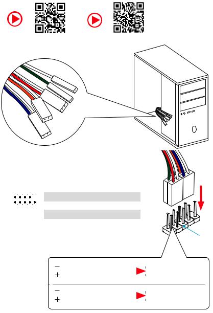
Connecting the Front Panel Header/
/ //
Youtube |
|
|
http://youtu.be/DPELIdVNZUI http://v.youku.com/v_show/id_XNjcyMTczMzM2.html
|
|
- |
|
|
|
LED |
|
|
LED+ |
POWER |
|
|
POWER |
||
|
LED |
|
|
SW |
HDD |
||
|
|
||
POWER |
|
|
|
SW |
|
|
|
RESET |
|
|
|
2 |
|
|
|
10 |
|
1 |
HDD LED + |
2 |
Power LED + |
|
|
|
|
|
|
|
|
|
|||
|
|
|
3 |
HDD LED - |
4 |
Power LED - |
||||
|
|
|
|
|
|
|
||||
|
|
|
|
|
|
|
|
|
|
|
|
|
|
|
|
|
|
5 |
Reset Switch |
6 |
Power Switch |
1 |
|
|
|
9 |
|
|||||
|
|
|
|
|
|
|
|
|||
|
|
JFP1 |
|
|
7 |
Reset Switch |
8 |
Power Switch |
||
|
|
|
|
|
|
|
|
|||
|
|
|
|
9 |
Reserved |
10 |
No Pin |
|||
|
|
|
|
|
|
|
||||
|
|
|
|
|
|
|
|
|
|
|
RESETSW
HDDLED
|
HDD LED |
|
|
|
|
|
HDD LED - |
|
|
|
|
|
|
||
|
|
|
|
|
|
|
HDD LED + |
|
|
|
|
|
|
|
|
|
|
|
|
|
|
|
POWER LED - |
|
POWER LED |
|
|
|
|
|
POWER LED + |
|
|
|
|
|
|
|
IV Quick Start
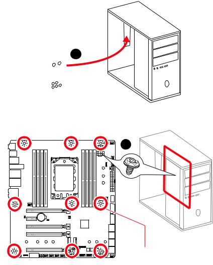
Installing the Motherboard/ /
/ /
1
2
BAT1
If you want to use the mounting screw hole, please refer to M.2 SHIELD FROZR1 & M.2 SHIELD FROZR2 section for removing the M.2 SHIELD FROZR 2.
Quick Start V
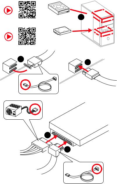
Installing SATA Drives/ SATA /
SATA / SATA / SATA
Youtube
1 
http://youtu.be/RZsMpqxythc
http://v.youku.com/v_show/ id_XNDkzODU5MTky.html
2 

 3
3
5
4
VI Quick Start
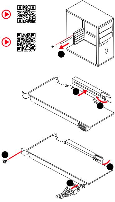
Installing a Graphics Card/ /
/ /
Youtube
http://youtu.be/mG0GZpr9w_A
http://v.youku.com/v_show/ 1 id_XNDkyOTc3MzQ4.html
3
2 
5
 4
4
6 

Quick Start VII
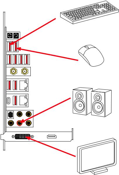
Connecting Peripheral Devices/ /
/ /
VIII Quick Start
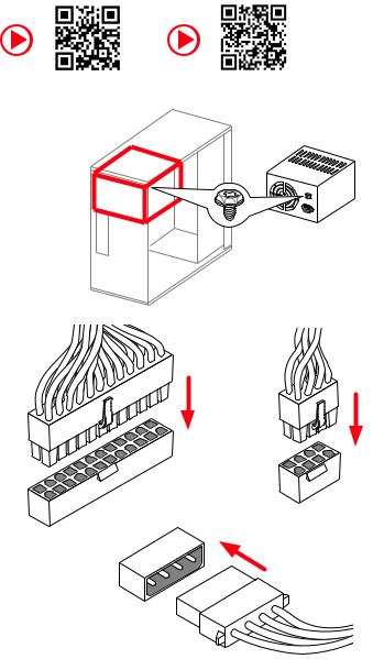
Connecting the Power Connectors/ // /
Youtube |
|
|
http://youtu.be/gkDYyR_83I4 http://v.youku.com/v_show/id_XNDkzODU0MDQw.html
ATX_PWR1 |
CPU_PWR1~2 |
|
PCIE_PWR1
Quick Start IX
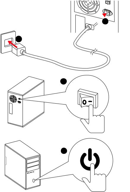
Power On/ / / /
 1
1
2
3
4
X Quick Start
Contents |
|
Safety Information................................................................................................. |
3 |
Specifications......................................................................................................... |
4 |
JCORSAIR1 Connector Specification...................................................................... |
9 |
Package contents .................................................................................................. |
9 |
Rear I/O Panel ..................................................................................................... |
10 |
LAN Port LED Status Table................................................................................... |
10 |
Audio Ports Configuration .................................................................................... |
10 |
Installing Antennas............................................................................................... |
11 |
Realtek Audio Console ......................................................................................... |
12 |
Overview of Components .................................................................................... |
14 |
CPU Socket ........................................................................................................... |
15 |
OC1: GAME BOOST Knob ..................................................................................... |
18 |
JOC_RT1: OC Retry Jumper ................................................................................. |
19 |
JOC_FS1: OC Force Enter BIOS Jumper .............................................................. |
19 |
JSLOW1: Slow Mode Booting Jumper.................................................................. |
19 |
DIMM Slots............................................................................................................ |
20 |
PCI_E1~5: PCIe Expansion Slots.......................................................................... |
21 |
M2_1~3: M.2 Slots (Key M) ................................................................................... |
23 |
Installing M.2 XPANDER-AERO card.................................................................... |
25 |
SATA1~8: SATA 6Gb/s Connectors ....................................................................... |
27 |
JFP1, JFP2: Front Panel Connectors ................................................................... |
27 |
CPU_PWR1~2, ATX_PWR1, PCIE_PWR1: Power Connectors.............................. |
28 |
JUSB1~2: USB 2.0 Connectors............................................................................. |
29 |
JUSB4~5: USB 3.1 Gen1 Connectors ................................................................... |
29 |
JUSB3: USB 3.1 Gen2 Type-C Connector............................................................. |
30 |
CPU_FAN1, PUMP_FAN1, SYS_FAN1~5, EXT_FAN1~3: Fan Connectors............ |
31 |
T_SEN1~3: Thermal Sensor Connectors ............................................................. |
31 |
JCI1: Chassis Intrusion Connector....................................................................... |
32 |
JTPM1: TPM Module Connector........................................................................... |
32 |
JAUD1: Front Audio Connector ............................................................................ |
33 |
JBAT1: Clear CMOS (Reset BIOS) Jumper ........................................................... |
33 |
JBLK_U1, JBLK_D1: Base clock Plus, Minus connectors................................... |
34 |
POWER1, RESET1: Power Button, Reset Button ................................................. |
34 |
JRGB1, JRGB2, JRAINBOW1: RGB LED connectors............................................ |
35 |
JCORSAIR1: CORSAIR Connector ........................................................................ |
36 |
Onboard LEDs...................................................................................................... |
37 |
EZ Debug LED....................................................................................................... |
37 |
Contents 1
DIMM LEDs ........................................................................................................... |
37 |
Fan LEDs............................................................................................................... |
37 |
JPWRLED1: LED light demonstration power input connector ............................ |
38 |
Debug Code LED................................................................................................... |
38 |
Hexadecimal Character Table .............................................................................. |
38 |
Boot Phases.......................................................................................................... |
38 |
Debug Code LED Table ......................................................................................... |
39 |
ACPI States Codes ................................................................................................ |
40 |
BIOS Setup........................................................................................................... |
42 |
Entering BIOS Setup............................................................................................. |
42 |
Resetting BIOS...................................................................................................... |
43 |
Updating BIOS....................................................................................................... |
43 |
EZ Mode ................................................................................................................ |
45 |
Advanced Mode .................................................................................................... |
47 |
OC Menu................................................................................................................ |
48 |
Software Description........................................................................................... |
53 |
Installing Windows® 10......................................................................................... |
53 |
Installing Drivers .................................................................................................. |
53 |
Installing Utilities ................................................................................................. |
53 |
2 Contents
Safety Information
yThe components included in this package are prone to damage from electrostatic discharge (ESD). Please adhere to the following instructions to ensure successful computer assembly.
yEnsure that all components are securely connected. Loose connections may cause the computer to not recognize a component or fail to start.
yHold the motherboard by the edges to avoid touching sensitive components.
yIt is recommended to wear an electrostatic discharge (ESD) wrist strap when handling the motherboard to prevent electrostatic damage. If an ESD wrist strap is not available, discharge yourself of static electricity by touching another metal object before handling the motherboard.
yStore the motherboard in an electrostatic shielding container or on an anti-static pad whenever the motherboard is not installed.
yBefore turning on the computer, ensure that there are no loose screws or metal components on the motherboard or anywhere within the computer case.
yDo not boot the computer before installation is completed. This could cause permanent damage to the components as well as injury to the user.
yIf you need help during any installation step, please consult a certified computer technician.
yAlways turn off the power supply and unplug the power cord from the power outlet before installing or removing any computer component.
yKeep this user guide for future reference.
yKeep this motherboard away from humidity.
yMake sure that your electrical outlet provides the same voltage as is indicated on the PSU, before connecting the PSU to the electrical outlet.
yPlace the power cord such a way that people can not step on it. Do not place anything over the power cord.
yAll cautions and warnings on the motherboard should be noted.
yIf any of the following situations arises, get the motherboard checked by service personnel:
Liquid has penetrated into the computer.
The motherboard has been exposed to moisture.
The motherboard does not work well or you can not get it work according to user guide.
The motherboard has been dropped and damaged.
The motherboard has obvious sign of breakage.
yDo not leave this motherboard in an environment above 60°C (140°F), it may damage the motherboard.
Safety Information 3

Specifications
CPU |
Supports AMD® Ryzen Threadripper processor for SocketTR4 |
|
|
|
|
Chipset |
AMD® X399 Chipset |
|
|
|
|
|
y8x DDR4 memory slots, support up to 128GB* |
|
|
yQuad channel memory architecture** |
|
Memory |
ySupports DDR4 3600+(OC)/ 3466(OC)/ 3333(OC)/ 3200(OC)/ |
|
|
3066(OC)/ 2933(OC)/ 2800(OC)/ 2667(OC)/ 2400/ 2133 MHz* |
|
|
* For the latest information about memory, please visit http://www.msi.com |
|
|
** Please refer the DIMM Slots section for more details. |
|
|
|
|
Expansion Slots |
y4x PCIe 3.0 x16 slots |
|
y1x PCIe 2.0 x1 slot |
||
|
||
|
|
|
Multi-GPU |
ySupports 3-Way NVIDIA® SLI™ Technology |
|
ySupports 3-Way AMD® CrossFire™ Technology |
||
|
||
|
|
|
LAN |
2x Intel I211 Gigabit LAN controllers |
|
|
|
|
|
Intel® Wireless-AC 9260 card |
|
Wireless LAN & |
ySupports Wi-Fi 802.11 ac, 2x2, Dual Band, (2.4GHz, 5GHz) |
|
Bluetooth® |
up to 1.73 Gbps speed. |
|
|
ySupports Bluetooth® 5 |
|
|
|
|
|
yAMD® X399 Chipset |
|
|
8x SATA 6Gb/s ports |
|
|
yAMD® CPU |
|
Storage |
3x M.2 slots (Key M) |
|
Supports up to PCIe 3.0 x4 and SATA 6Gb/s |
||
|
||
|
M2_1, M2_3 slots support 2242/ 2260 /2280 storage |
|
|
devices |
|
|
M2_2 slot supports 2242/ 2260 /2280/ 22110 storage |
|
|
devices |
|
|
|
|
|
AMD® X399 Chipset |
|
RAID |
ySupports RAID 0, RAID 1 and RAID 10 for SATA storage |
|
|
devices |
|
|
|
|
|
Continued on next page |
4 Specifications

Continued from previous page
|
yASMedia® ASM3142 Chipset |
|
1x USB 3.1 Gen2 (SuperSpeed USB 10Gbps) Type-C port |
|
available through the internal USB connector |
|
yAMD® X399 Chipset |
|
1x USB 3.1 Gen1 (SuperSpeed USB) Type-A port on the |
|
back panel |
|
1x USB 3.1 Gen1 (SuperSpeed USB) Type-C port on the |
USB |
back panel |
|
4x USB 3.1 Gen1 (SuperSpeed USB) ports available |
|
through the internal USB connectors |
|
4x USB 2.0 (High-speed USB) ports available through |
|
the internal USB connectors |
|
yAMD® CPU |
|
8x USB 3.1 Gen1 (SuperSpeed USB) Type-A ports on the |
|
back panel |
|
|
|
yRealtek® ALC1220 Codec |
Audio |
y7.1-Channel High Definition Audio |
|
ySupports S/PDIF output |
|
|
|
y1x Clear CMOS button |
|
y1x BIOS FLASHBACK+ button |
|
y8x USB 3.1 Gen1 Type-A ports |
|
1x BIOS FLASHBACK+ port |
Back Panel |
y2x WiFi antenna connectors |
Connectors |
y1x USB 3.1 Gen1 Type-A port |
|
|
|
y1x USB 3.1 Gen1 Type-C port |
|
y2x LAN (RJ45) ports |
|
y5x OFC audio jacks |
|
y1x Optical S/PDIF OUT connector |
|
|
|
Continued on next page |
Specifications 5

Continued from previous page
y1x 24-pin ATX main power connector
y2x 8-pin ATX 12V power connector
y1x flat 4-pin ATX 12V power connector*
y8x SATA 6Gb/s connectors
y2x USB 2.0 connectors (supports additional 4 USB 2.0 ports)
y2x USB 3.1 Gen1 connectors (supports additional 4 USB 3.1 Gen1 ports)
y1x USB 3.1 Gen2 Type-C port
y1x 4-pin CPU fan connector
y1x 4-pin Water Pump connector
Internal Connectors y5x 4-pin system fan connectors
|
y3x 4-pin extend fan connectors |
|
y2x Front panel connectors |
|
y1x Front panel audio connector |
|
y2x 5050 RGB LED strip 12V connector (JRGB1~2) |
|
y1x WS2812B Individually Addressable RGB LED strip 5V |
|
connector (JRAINBOW1) |
|
y1x CORSAIR connector (JCORSAIR1) |
|
y1x TPM module connector |
|
y3x 2-pin Thermal Sensors connectors |
|
* Provides additional power to PCIe x16 slots |
|
|
|
y1x GAME BOOST knob |
Internal Buttons |
y1x Power button |
|
y1x Reset button |
|
|
|
y1x Clear CMOS jumper |
|
y1x OC retry connector |
|
y1x OC force enter BIOS connector |
Jumper |
y1x Chassis Intrusion connector |
|
y1x Slow mode connector |
|
y1x JBLK_U1 connector |
|
y1x JBLK_D1 connector |
|
|
Debug LED |
y1x 2-Digit Debug Code LED |
|
|
|
Continued on next page |
6 Specifications

|
Continued from previous page |
|
|
|
|
I/O Controller |
NUVOTON NCT6797 Controller Chip |
|
|
|
|
|
yCPU/System temperature detection |
|
Hardware Monitor |
yCPU/System fan speed detection |
|
|
yCPU/System fan speed control |
|
|
|
|
Form Factor |
yEATX Form Factor |
|
y12 in. x 10.7 in. (30.4 cm x 27.2 cm) |
||
|
||
|
|
|
|
y1x 128 Mb flash |
|
BIOS Features |
yUEFI AMI BIOS |
|
yACPI 6.0, SM BIOS 2.8 |
||
|
||
|
yMulti-language |
|
|
|
|
|
yDrivers |
|
|
yAPP MANAGER |
|
|
ySUPER CHARGER |
|
|
yCOMMAND CENTER |
|
|
yLIVE UPDATE 6 |
|
|
ySMART TOOL |
|
|
yGAMING APP |
|
Software |
yX-BOOST |
|
yMYSTIC LIGHT (LED) |
||
|
||
|
yRAMDISK |
|
|
yGAMING LAN MANAGER |
|
|
yNahimic 3 |
|
|
yOpen Broadcaster Software (OBS) |
|
|
yCPU-Z MSI GAMING |
|
|
yNorton™ Internet Security Solution |
|
|
yGoogle Chrome™ ,Google Toolbar, Google Drive |
|
|
|
|
|
Continued on next page |
Specifications 7
Continued from previous page
|
yAudio Boost 4 |
|
yNahimic 3 |
|
yGAMING LAN with Gaming LAN Manager |
|
yIntel WiFi |
|
yTriple Turbo M.2 |
|
yPump Fan |
|
ySmart Fan Control |
|
yMystic Light |
|
yMystic Light Extension |
|
yMystic light SYNC |
|
yEZ DEBUG LED |
|
yDDR4 Steel Armor |
|
yM.2 Shield FROZR |
|
yPCI-E Steel Armor |
Special Features |
yMulti GPU – SLI Technology |
|
yMulti GPU – CrossFire Technology |
|
yDDR4 Boost |
|
yGAME Boost |
|
yCore Boost |
|
yVoice Boost |
|
yOC Engine (Clock gen) |
|
yUSB with type A+C |
|
yAMD Turbo USB3.1 Gen 1 |
|
yFront Lightning USB 3.1 Gen 2 Type-C |
|
yVR Ready |
|
yGAMING HOTKEY |
|
yGAMING MOUSE Control |
|
yClick BIOS 5 |
|
yBIOS FLASHBACK+ |
|
|
8 Specifications

JCORSAIR1 Connector Specification
Supporting CORSAIR RGB Products |
Maximum connection |
|
|
Lighting PRO RGB LED Strip |
20 |
|
|
HD RGB Fan |
6 |
|
|
SP RGB Fan |
6 |
|
|
LL RGB Fan |
6 |
|
|
Package contents
Please check the contents of your motherboard package. It should contain:
yUser Manual
yQuick Installation Guide
yDriver DVD
ySATA 6G Cable x4
yLED Y CABLE
yLED JCORSAIR CABLE
yLED JRAINBOW CABLE
ySENSOR CABLE x3
yM.2 Xpander-AERO
ySLI HB BRIDGE M
yWiFi antenna
yCase Badge
yHDD Sticker
yVIP card
yI/O Shielding
yM.2 Screw x3
Important
If any of the above items are damaged or missing, please contact your retailer.
Package contents 9
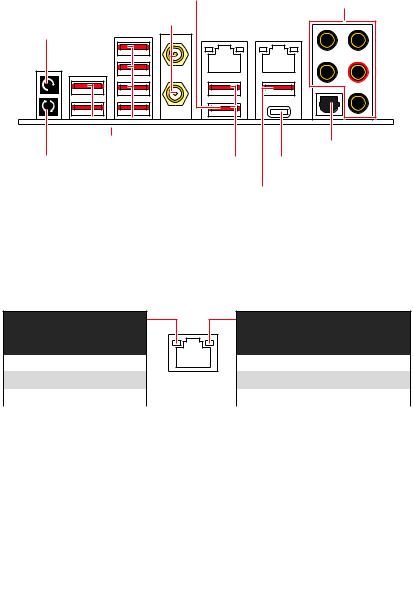
Rear I/O Panel
|
|
BIOS FLASHBACK+ port |
Audio Ports |
|
|
WiFi Antenna |
|
||
|
|
|
||
Clear CMOS |
Connectors |
LAN |
|
|
|
|
|
|
|
button |
|
|
|
|
USB 3.1 Gen1 Type-A |
|
|
Optical S/PDIF-Out |
|
|
|
|
|
|
BIOS |
USB 3.1 Gen1 Type-A |
USB 3.1 Gen1 Type-C |
||
FLASHBACK+ |
(VR READY ports) |
|
|
|
button |
|
USB 3.1 Gen1 Type-A |
||
|
|
|||
yClear CMOS button - Power off your computer. Press and hold the Clear CMOS button for about 5-10 seconds to reset BIOS to default values.
yBIOS FLASHBACK+ port/ button - Please refer to page 44 for Updating BIOS with BIOS FLASHBACK+.
LAN Port LED Status Table
Link/ Activity LED
Status |
Description |
|
|
Off |
No link |
|
|
Yellow |
Linked |
|
|
Blinking |
Data activity |
|
|
Speed LED
Status |
Description |
|
|
Off |
10 Mbps connection |
|
|
Green |
100 Mbps connection |
|
|
Orange |
1 Gbps connection |
|
|
Audio Ports Configuration
|
|
|
|
|
|
|
|
|
|
Audio Ports |
|
Channel |
|
|
|
|
|
|
|
|
|
|
|
|
|
|
|||
|
|
|
|
|
|
|
|
|
|
|
|
|
|
|
|
|
|
|
|
|
|
|
|
|
|
2 |
4 |
6 |
8 |
|
|
|
|
|
|
|
|
|
|
|
|
|
|
|
|
|
|
|
|
|
|
|
|
|
Center/ Subwoofer Out |
|
|
● |
● |
|
|
|
|
|
|
|
|
|
|
|
||||
|
|
|
|
|
|
|
|
|
|
Rear Speaker Out |
|
● |
● |
● |
|
|
|
|
|
|
|
|
|
|
|
||||
|
|
|
|
|
|
|
|
|
|
Line-In/ Side Speaker Out |
|
|
|
● |
|
|
|
|
|
|
|
|
|
|
|
|
|||
|
|
|
|
|
|
|
|
|
|
Line-Out/ Front Speaker Out |
● |
● |
● |
● |
|
|
|
|
|
|
|
|
|
|
|||||
|
|
|
|
|
|
|
|
|
|
Mic In |
|
|
|
|
|
|
|
|
|
|
|
|
|
|
|
|
|
||
|
|
|
|
|
|
|
|
|
|
|
|
|
|
|
|
|
|
|
|
|
|
|
|
|
(●: connected, Blank: empty) |
|
|
|
|
10 Rear I/O Panel
Installing Antennas
1.Combine the antenna with the base.
2.Screw two antenna cables tight to the WiFi antenna connectors as shown.
2 

1
3. Place the antenna as high as possible.
Rear I/O Panel 11
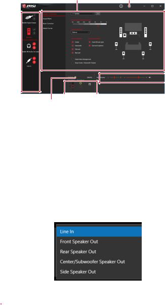
Realtek Audio Console
After Realtek Audio Console is installed. You can use it to change sound settings to get better sound experience.
Application Enhancement |
Advanced Settings |
Device 
Selection
 Main Volume
|
|
|
|
|
Connector Settings |
|
Jack Status |
||
|
||||
|
|
|
||
yDevice Selection - allows you to select a audio output source to change the related options. The check sign indicates the devices as default.
yApplication Enhancement - the array of options will provide you a complete guidance of anticipated sound effect for both output and input device.
yAdvanced Settings - provides the mechanism to deal with 2 independent audio streams.
yMain Volume - controls the volume or balance the right/left side of the speakers that you plugged in front or rear panel by adjust the bar.
yJack Status - depicts all render and capture devices currently connected with your computer.
yConnector Settings - configures the connection settings.
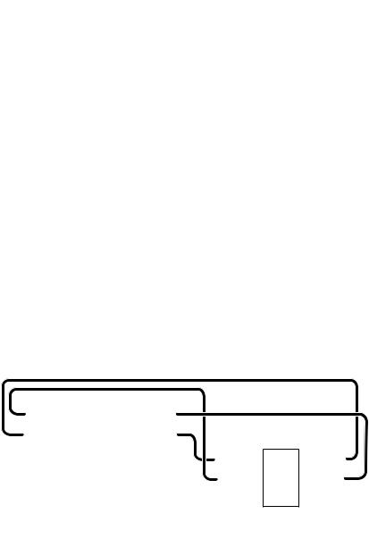
Auto popup dialog
When you plug into a device at an audio jack, a dialogue window will pop up asking you which device is current connected.
Each jack corresponds to its default setting as shown on the next page.
 Important
The pictures above for reference only and may vary from the product you purchased.
12 Rear I/O Panel
Audio jacks to headphone and microphone diagram
Audio jacks to stereo speakers diagram
AUDIO INPUT
Audio jacks to 7.1-channel speakers diagram
AUDIO INPUT
Rear |
Front |
Side |
Center/ |
|
Subwoofer |
Rear I/O Panel 13
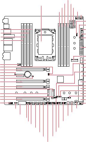
Overview of Components
DIMMC1
DIMMC2
DIMMD1
DIMMD2
SYS_FAN1
JBLK_D1
PCI_E1
JCI1
PCI_E2
JBAT1
PCI_E3
PCI_E4
M2_1
M2_2
JPWRLED1
PCI_E5
JAUD1
|
DIMMB2 |
||
CPU Socket |
DIMMB1 |
CPU_PWR1 |
|
DIMMA2 |
CPU_PWR2 |
||
|
|||
|
DIMMA1 |
CPU_FAN1 |
|
|
|
PUMP_FAN1 |
|
|
|
JRGB2 |
|
|
|
T_SEN3 |
|
|
|
SYS_FAN5 |
|
|
|
SYS_FAN3 |
|
|
|
JCORSAIR1 |
|
|
|
ATX_PWR1 |
|
|
|
M2_3 |
|
|
|
JUSB3 |
|
|
|
JBLK_U1 |
|
|
|
JUSB5 |
|
BAT1 |
|
JSLOW1 |
|
|
JUSB4 |
||
|
|
||
|
|
SATA▼1▲2 |
|
|
|
JOC_RT1 |
|
|
|
SATA▼3▲4 |
|
|
|
JOC_FS1 |
|
|
|
SATA▼5▲6 |
|
|
|
JRAINBOW1 |
|
|
|
SATA▼7▲8 |
|
|
|
SYS_FAN4 |
|
JRGB1 |
|
OC1 |
|
PCIE_PWR1 |
|
POWER1 |
|
RESET1 |
|||
T_SEN1 |
|||
|
|
||
T_SEN2 |
JUSB2 |
|
|
EXT_FAN1 |
|
|
|
EXT_FAN2 |
JUSB1 |
|
|
SYS_FAN2 |
JFP2 |
|
|
SYS_FAN3 |
JFP1 |
|
|
JTPM1
14 Overview of Components
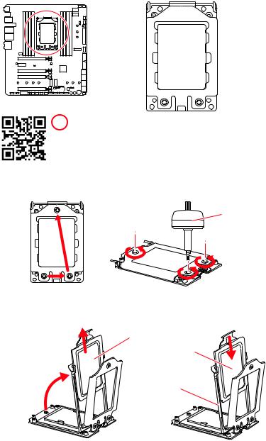
CPU Socket
Please use the Torx screwdriver come with the AMD CPU and follow the steps below to install the CPU.
1
 3 2
3 2
 Video Demonstration
Watch the video to learn how to unbox and install AMD Ryzen Threadripper CPU.
https://youtu.be/yk4EpVUU03E
1.Loosen load plate screws with the AMD Torx screwdriver in the sequence 3→2→1. The load plate will automatically lift up to the fully open position.
1 |
AMD Torx screwdriver |
|
3 |
2 |
2.Slide out the External Cap from the frame rail, and then slide the Carrier Frame with CPU into the frame rail. Make sure that the Carrier Frame with CPU has been properly installed in the frame rail.
External Cap
Carrier Frame with CPU
Frame rail
Overview of Components 15
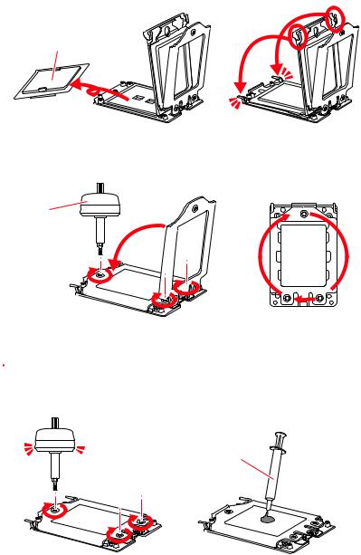
3. Remove the protective pin cap, and then close and buckle the frame rail.
Protective pin cap
4.Close the load plate, and then turn the load plate screws clockwise a little with the AMD Torx screwdriver in the sequence 1→2→3→1→2→3 until they are snug.
AMD Torx screwdriver |
1 |
3 2 
5. Tighten load plate screws until you hear a click from the AMD Torx screwdriver.
 Important
If the load plate is not secured properly, the computer will not power on.
6. Apply thermal paste on the top of the CPU.
 Click
Click
Thermal paste
16 Overview of Components

7.Place the heatsink on the motherboard, align the bolts with the mounting nuts on the motherboard. Then, tighten the bolts in a diagonal order to spread the tension properly across the sides.
8.Finally, attach the CPU fan cable to the CPU fan connector on the motherboard.
2 |
3 |
4 |
1 |
 Important
yAlways unplug the power cord from the power outlet before installing or removing the CPU.
yPlease retain the protective caps after installing the processor. MSI will deal with Return Merchandise Authorization (RMA) requests if only the motherboard comes with the protective caps on the CPU socket.
yWhen installing a CPU, always remember to install a CPU heatsink. A CPU heatsink is necessary to prevent overheating and maintain system stability.
yConfirm that the CPU heatsink has formed a tight seal with the CPU before booting your system.
yOverheating can seriously damage the CPU and motherboard. Always make sure the cooling fans work properly to protect the CPU from overheating. Be sure to apply an even layer of thermal paste (or thermal tape) between the CPU and the heatsink to enhance heat dissipation.
yWhenever the CPU is not installed, always protect the CPU socket pins by covering the socket with the plastic cap.
yIf you purchased a separate CPU and heatsink/ cooler, Please refer to the documentation in the heatsink/ cooler package for more details about installation.
yThis motherboard is designed to support overclocking. Before attempting to overclock, please make sure that all other system components can tolerate overclocking. Any attempt to operate beyond product specifications is not recommended. MSI® does not guarantee the damages or risks caused by inadequate operation beyond product specifications.
Overview of Components 17
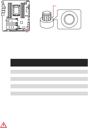
OC1: GAME BOOST Knob
This knob allows you to manually select a stage from number 0 (default) to number 11 (extreme) for overclocking the processor. The processor’s voltage and frequency will be automatically adjusted after you power on your computer.
GAME BOOST knob
1 1
0 1
8
0
6
1
2
4
Using GAME BOOST Knob
To setup the GAME BOOST knob, take the following steps:
1.Set the GAME BOOST knob to hardware mode in BIOS Setup.
2.Power off the computer.
3.Rotate the GAME BOOST knob to select the overclocking stage as you desire.
Stage |
|
CPU Frequency |
|
||
TR 1950X |
TR 1920X |
TR 1920 |
TR 1900X |
||
|
|||||
0 |
3.4 GHz |
3.5 GHz |
3.2 GHz |
3.8 GHz |
|
1 |
3.75 GHz |
3.85 GHz |
3.55 GHz |
4.15 GHz |
|
2 |
3.8 GHz |
3.9 GHz |
3.6 GHz |
4.2 GHz |
|
4 |
3.85 GHz |
3.95 GHz |
3.65 GHz |
4.25 GHz |
|
6 |
3.9 GHz |
4 GHz |
3.7 GHz |
4.3 GHz |
|
8 |
3.95 GHz |
4.05 GHz |
3.75 GHz |
4.35 GHz |
|
10 |
4 GHz |
4.1 GHz |
3.8 GHz |
4.4 GHz |
|
11 |
4.1 GHz |
4.2 GHz |
3.9 GHz |
4.5 GHz |
|
4.Power on and then GAME BOOST will automatically overclock processor depending on the stage you selected.
To disable GAME BOOST:
1.Set the GAME BOOST knob to HW mode in BIOS Setup.
2.Power off the computer.
3.Rotate the GAME BOOST knob to 0 and then power on. The configuration parameters will be returned to default values.
Important
yYou can also control the GAME BOOST function in BIOS Setup or with MSI COMMAND CENTER software.
yIn order to optimize performance and improve system stability, when you activate the GAME BOOST function, please leave the settings in the BIOS > OC menu unchanged.
18 Overview of Components
yThe success of overclocking depends on the components of your computer.
yWe do not guarantee the GAME BOOST overclocking range or the damages/ risks caused by overclocking behavior.
yMSI components are recommended for better compatibility when using GAME BOOST function.
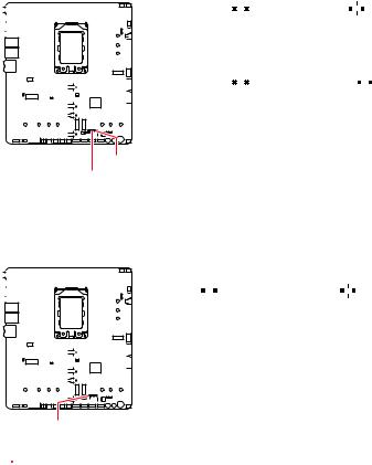
JOC_RT1: OC Retry Jumper
When you close this jumper, the system will keep retrying OC items until it boot up successfully.
JOC_FS1: OC Force Enter BIOS Jumper
When you close this jumper, the system will be forced access to the BIOS and skip OC failure messages .
|
|
|
|
|
|
|
|
|
|
|
|
|
|
|
|
|
|
|
JOC_RT1 |
|
|
|
|
|
|
|
|
|
|
|
|
|
|
|
|
|
|
|
|
|
|
|
|
|
|
|
|
|
|
|
|
|
|
|
|
Normal |
Keep retrying OC |
||||||||||||||||
|
|
|
|
|
|
|
|
|
|
|
|
|
|
|
|
|
|
|||||||||||||||||||
|
|
|
|
|
|
|
|
|
|
|
|
|
|
|
|
|
|
|
(default) |
|
|
|
|
|
|
|
|
|
|
|
||||||
|
|
|
|
|
|
|
|
|
|
|
|
|
|
|
|
|
|
|
|
|
|
|
|
|
|
|
|
|
||||||||
|
|
|
|
|
|
|
|
|
|
|
|
|
|
|
|
|
||||||||||||||||||||
|
|
|
|
|
|
|
|
|
|
|
|
|
|
|
|
|
|
|
|
|
|
|
|
|
|
|
|
|
|
|
|
|
|
|
|
|
|
|
|
|
|
|
|
|
|
|
|
|
|
|
|
|
|
|
|
JOC_FS1 |
|
|
|
|
|
|
|
|
|
|
|
|
|
|
|
|
|
|
|
|
|
|
|
|
|
|
|
|
|
|
|
|
|
|
|
|
|
|
|
|
|
|
|
|
|
|
|
|
|
|
|
|
||
|
|
|
|
|
|
|
|
|
|
|
|
|
|
|
|
|
|
|
Normal |
Force access to the |
||||||||||||||||
|
|
|
|
|
|
|
|
|
|
|
|
|
|
|
|
|
|
|
(default) |
BIOS and skip OC failure |
||||||||||||||||
|
|
|
|
|
|
|
|
|
|
|
|
|
|
|
|
|
|
|
|
|
|
|
|
|
|
messages |
||||||||||
JOC_FS1 JOC_RT1
JSLOW1: Slow Mode Booting Jumper
This jumper is used for LN2 cooling solution, that provides the extreme overclocking conditions, to boot at a stable processor frequency and to prevent the system from crashing.
|
|
|
|
|
|
|
|
|
|
|
|
|
|
|
|
|
|
|
|
|
|
|
|
|
|
|
|
|
|
|
|
|
|
|
|
|
|
|
|
|
|
|
|
|
|
|
|
|
|
|
|
|
|
|
|
|
|
|
|
|
|
|
|
|
|
|
|
|
|
|
|
|
|
|
|
|
|
|
|
|
|
|
|
|
|
|
|
|
|
|
|
|
|
|
|
|
|
|
|
|
|
|
|
Normal |
Enabled |
|||||
|
|
|
|
|||||||||||||||||||||||||||||||||
|
|
|
|
|
|
|
|
|
|
|
|
|
|
|
|
|
|
|
|
|
|
|
|
|
|
|
|
|
|
(default) |
(Please enable this jumper |
|||||
|
|
|
|
|
|
|
|
|
|
|
|
|
|
|
|
|
|
|
|
|
|
|
|
|
|
|
|
|
|
|||||||
|
|
|
|
|
|
|
|
|
|
|
|
|
|
|
|
|
|
|
|
|
|
|
|
|
|
|
|
|
|
|||||||
|
|
|
|
|
|
|
|
|
|
|
|
|
|
|
|
|
|
|
|
|
|
|
|
|
|
|
|
|
|
|
|
|
|
during BIOS POST.) |
||
|
|
|
|
|
|
|
|
|
|
|
|
|
|
|
|
|
|
|
|
|
|
|
|
|
|
|
|
|
|
|
|
|
|
|
|
|
|
|
|
|
|
|
|
|
|
|
|
|
|
|
|
|
|
|
|
|
|
|
|
|
|
|
|
|
|
|
|
|
|
|
|
|
|
JSLOW1
 Important
yUsers will try extreme low temperature overclocking at their own risks. The overclocking results will vary according to the CPU version.
yPlease don’t switch to Enabled when power-off or the system will be un-bootable.
Overview of Components 19
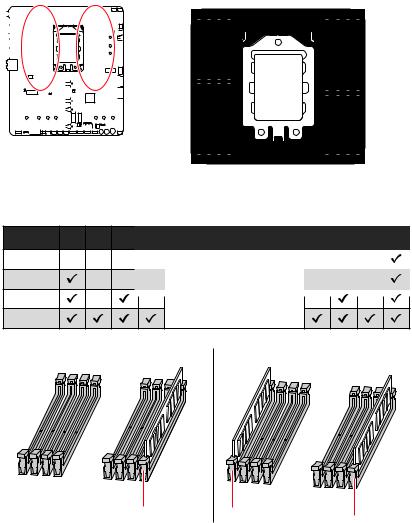
DIMM Slots
|
|
|
|
|
|
|
|
|
|
|
|
|
|
|
|
|
|
|
|
|
|
|
|
|
|
|
|
|
|
|
|
|
|
|
|
|
|
|
|
|
|
|
|
|
|
|
|
|
|
|
|
|
|
|
|
|
|
|
|
|
|
|
|
|
|
|
|
|
|
|
|
|
|
|
|
|
|
|
|
|
|
|
|
|
|
|
|
|
|
|
|
|
|
|
|
|
|
|
|
|
|
|
|
|
|
|
|
|
|
|
|
|
|
|
|
|
|
|
|
|
|
|
|
|
|
|
|
|
|
|
|
|
|
|
|
|
|
|
|
|
|
|
|
|
|
|
|
|
|
|
|
|
|
|
|
|
|
|
|
|
|
|
|
|
|
|
|
|
|
|
|
|
|
|
|
|
|
|
|
|
|
|
|
|
|
|
|
|
|
|
|
|
|
|
|
|
|
|
|
|
|
|
|
|
|
|
|
|
|
|
|
|
|
|
|
|
|
|
|
|
|
|
|
|
|
|
|
|
|
|
|
|
|
|
|
|
|
|
|
|
|
|
|
|
|
|
|
|
|
|
|
|
|
|
|
|
|
|
|
|
|
|
|
|
|
|
|
|
|
|
|
|
|
|
|
|
|
|
|
|
|
|
|
|
|
|
|
|
|
|
|
|
|
|
|
|
|
|
|
|
|
|
|
|
|
|
|
|
|
|
|
|
|
|
|
|
|
|
|
|
|
|
|
|
|
|
|
|
|
|
|
|
|
|
|
|
|
|
|
|
|
|
|
|
|
|
|
|
|
|
|
|
|
|
|
|
|
|
|
|
|
|
|
|
|
|
|
|
|
|
|
|
|
|
|
|
|
|
|
|
|
|
|
|
|
|
|
|
|
|
|
|
|
|
|
|
|
|
|
|
|
|
|
|
|
|
|
|
|
|
|
|
|
|
|
|
|
|
|
|
|
|
|
|
|
|
|
|
|
|
|
|
|
|
|
|
|
|
|
|
|
|
|
|
|
|
|
|
|
|
|
|
|
|
|
|
|
|
|
|
|
|
|
|
|
|
|
|
|
|
D2D1C2C1 |
A1A2B1B2 |
|||||||||||||||||
Memory module installation recommendation |
|
|
|
|
||||
D2 |
D1 |
C2 |
C1 |
CPU Socket |
A1 |
A2 |
B1 |
B2 |
1 DIMM |
|
|
|
|
|
|
|
|
2 DIMMs |
|
|
|
SocketTR4 CPU |
|
|
|
|
4 DIMMs |
|
|
|
|
|
|
|
|
|
|
|
|
|
|
|
|
|
8 DIMMs |
|
|
|
|
|
|
|
|
 DIMMB2
  DIMMD2
 DIMMB2
20 Overview of Components
Loading...