


K9NGM/ K9NGM2 Series
MS-7252 (V1.X) Mainboard
G52-72521X4
i

Copyright Notice
The material in this document is the intellectual property of M ICRO-STAR INTERNATIONAL. We take every care in the preparation of this document, but no guarantee is given as to the correctness of its contents. Our products are under continual improvement and we reserve the right to make changes without notice.
Trademarks
All trademarks are the properties of their respective owners.
NVIDIA, the NVIDIA logo, DualNet, and nForce are registered trademarks or trademarks of NVIDIA Corporation in the United States and/or other countries.
AMD, Athlon™, Athlon™ XP, Thoroughbred™, and Duron™ are registered trademarks of AMD Corporation.
Intel® and Pentium® are registered trademarks of Intel Corporation.
PS/2 and OS®/2 are registered trademarks of International Business Machines Corporation.
Windows® 95/98/2000/NT/XP are registered trademarks of Microsoft Corporation. Netware® is a registered trademark of Novell, Inc.
Award® is a registered trademark of Phoenix Technologies Ltd. AMI® is a registered trademark of American Megatrends Inc.
Revision History
Revision |
Revision History |
Date |
V1.0 |
First release for EU |
June 2006 |
Technical Support
If a problem arises with your system and no solution can be obtained from the user’s manual, please contact your place of purchase or local distributor. Alternatively, please try the following help resources for further guidance.
 Visit the MSI website for FAQ, technical guide, BIOS updates, driver updates, and other information: http://www.msi.com.tw/program/service/faq/ faq/esc_faq_list.php
 Contact our technical staff at: http://support.msi.com.tw/
ii

Safety Instructions
1.Always read the safety instructions carefully.
2.Keep this User’s Manual for future reference.
3.Keep this equipment away from humidity.
4.Lay this equipment on a reliable flat surface before setting it up.
5.The openings on the enclosure are for air convection hence protects the equipment from overheating. DO NOT COVER THE OPENINGS.
6.Make sure the voltage of the power source and adjust properly 110/220V before connecting the equipment to the power inlet.
7.Place the power cord such a way that people can not step on it. Do not place anything over the power cord.
8.Always Unplug the Power Cord before inserting any add-on card or module.
9.All cautions and warnings on the equipment should be noted.
10.Never pour any liquid into the opening that could damage or cause electrical shock.
11.If any of the following situations arises, get the equipment checked by service personnel:
†The power cord or plug is damaged.
†Liquid has penetrated into the equipment.
†The equipment has been exposed to moisture.
†The equipment does not work well or you can not get it work according to User’s Manual.
†The equipment has dropped and damaged.
†The equipment has obvious sign of breakage.
12.DONOT LEAVETHIS EQUIPMENT INANENVIRONMENT UNCONDITIONED, STORAGE TEMPERATURE ABOVE 600 C (1400F), IT MAYDAMAGE THE EQUIPMENT.
CAUTION: Danger of explosion if battery is incorrectly replaced. Replace only with the same or equivalent type recommended by the manufacturer.
iii
FCC-B Radio Frequency Interference Statement
This equipment has been tested and found to comply with the limits for a Class B digital device, pursuant to Part
15 of the FCC Rules. These limits are designed to provide reasonable protection against harmful interference in a residential installation. This equipment generates, uses and can radiate radio frequency energy and, if not installed and used in accordance with the instructions, may cause harmful interference to radio communications. However, there is no guarantee that interference will not occur in a particular installation. If this equipment does cause harmful interference to radio or television reception, which can be determined by turning the equipment off and on, the user is encouraged to try to correct the interference by one or more of the measures listed below.
†Reorient or relocate the receiving antenna.
†Increase the separation between the equipment and receiver.
†Connect the equipment into an outlet on a circuit different from that to which the receiver is connected.
†Consult the dealer or an experienced radio/television technician for help.
Notice 1
The changes or modifications not expressly approved by the party responsible for compliance could void the user’s authority to operate the equipment.
Notice 2
Shielded interface cables and A.C. power cord, if any, must be used in order to comply with the emission limits.
VOIR LANOTICE D’INSTALLATIONAVANT DE RACCORDER AU RESEAU.
Micro-Star International
MS-7252
This device complies with Part 15 of the FCC Rules. Operation is subject to the following two conditions:
(1)this device may not cause harmful interference, and
(2)this device must accept any interference received, including interference that may cause undesired operation.
iv

WEEE (Waste Electrical and Electronic Equipment) Statement
v

vi

vii
|
CONTENTS |
|
Copyright |
Notice ......................................................................................................... |
ii |
Trademarks .................................................................................................................. |
ii |
|
Revision |
History ......................................................................................................... |
ii |
Technical |
Support ...................................................................................................... |
ii |
Safety Instructions ................................................................................................... |
iii |
|
FCC-B Radio Frequency Interference Statement ............................................. |
iv |
|
WEEE (Waste Electrical and Electronic Equipment) Statement ....................... |
v |
|
English ...................................................................................................................... |
|
En-1 |
Specifications .................................................................................................... |
En-1 |
|
How to use this Installation Guide? ................................................................. |
En-3 |
|
Central Processing Unit: CPU ........................................................................... |
En-4 |
|
Memory............................................................................................................... |
En-5 |
|
Connectors, Jumpers, Slots ............................................................................. |
En-6 |
|
Back Panel ........................................................................................................ |
En-12 |
|
BIOS Setup ....................................................................................................... |
En-14 |
|
Software Information ...................................................................................... |
En-16 |
|
German .................................................................................................................... |
|
De-1 |
Spezifikationen .................................................................................................. |
De-1 |
|
“Wie Sie diese Installationsanleitung verwenden.” ........................................ |
De-3 |
|
Hauptprozessor: CPU ....................................................................................... |
De-4 |
|
Speicher ............................................................................................................. |
De-5 |
|
Anschlüsse, Steckbrücken und Slots ............................................................. |
De-6 |
|
Hinteres Anschlusspaneel ............................................................................. |
De-12 |
|
BIOS Setup ....................................................................................................... |
De-14 |
|
Software Information ...................................................................................... |
De-16 |
|
French ....................................................................................................................... |
|
Fr-1 |
Spécificités ......................................................................................................... |
Fr-1 |
|
“Comment utiliser ce manuel?” .......................................................................... |
Fr-3 |
|
Central Processing Unit: CPU ............................................................................ |
Fr-4 |
|
Mémoire ............................................................................................................... |
Fr-5 |
|
Connecteurs, Jumper, Slots .............................................................................. |
Fr-6 |
|
Panneau Arrière ............................................................................................... |
Fr-12 |
|
Installation du BIOS .......................................................................................... |
Fr-14 |
|
Information de Logiciel ..................................................................................... |
Fr-16 |
|
viii

Installation Guide
Specifications
 Processor Support*
- AMD® Athlon 64 and Athlon FX in the socket AM2 package.
 Supported FSB
- HyperTransport supporting speed up to 1GHz (2000MT/s)
 Chipset
- nVIDIA® C51G & MCP51G (for K9NGM series), C51PV and MCP51 (for K9NGM2 series)
Memory Support**
-DDRII 400/ 533/ 667/ 800 SDRAM (8GB Max)
-4 DDRII DIMMs (Dual Channel, 240-pin/ 1.8V/ non-ECC)
LAN
- Supports 10/100/1000 M/bit LAN by Vitesse VSC8601 or 10/100 M/bit LAN by Realtek RTL8201CL
 IEEE 1394 (optional)
-Controlled by VIA® VT6308P
-Transfer rate is up to 400 Mb/s
Audio
-Controlled by Realtek ALC883
-Supports 8 channels audio out
-Azalis 1.0 Audio solution
IDE
-1 IDE port controlled by nForce MCP51G/ MCP51
-Supports Ultra DMA 133/100/ 66 mode, and PIO Bus Master mode
SATA
-K9NGM2 series supports 4 SATAII ports (SATA1~ 4, 300 MB/s)
-K9NGM series supports 2 SATAII ports (SATA1~2, 300 MB/s)
RAID
-SATA1~4 support RAID0/ RAID1/ RAID0+1/ RAID5 or JBOD mode (for K9NGM2 series)
-SATA1~2 support RAID0/ RAID1 or JBOD mode (for K9NGM series)
Floppy
- 1 floppy port
 Connectors
  Back panel
-1 PS/2 mouse port
-1 PS/2 keyboard port
-1 VGA port
-1 DVI port (only for K9NGM2 series)
-1 Parallel port support SPP/EPP/ECP mode
-1 IEEE 1394 port (optional)
-4 USB 2.0 ports
-1 LAN jack
-3 flexible audio jacks
On-Board Pinheaders
-2 USB 2.0 pinheaders
-1 IEEE 1394 pinheader
-1 TV-out pinheader (only for K9NGM2 series)
-1 SPDIF-out pinheader / 1 SPDIF-in pinheader
-1 COM port pinheader
-1 Audio-out pinheader
Slots
-1 PCI Express x 16 slot
-1 PCI Express x 1 slot
-2 PCI slots support 3.3V/ 5V PCI bus interface
 Form Factor
- Micro-ATX (24.4 cm X 24.4 cm)
Mounting
- 8 mounting holes
*For the latest information about CPU, please visit http:// www.ms i.com. tw/pro gram/product s/mainboard/ mbd/ pro_mbd_cpu_support.php
**For the updated supporting memory modules, please visit http://www.msi.com.tw/program/products/mainboard/mbd/ pro_mbd_trp_list.php
English
En-1

 MS-7252 Mainboard
|
30 |
35 |
38 |
|
|
|
34 |
29 |
|
|
37 |
|
|
|
|
33 |
32 |
36 |
39 |
(for K9NGM2 series only)
(for K9NGM2 |
4 |
series only) |
18 |
|
23 |
1 |
3 |
|
|
|
15 |
|
|
|
21 |
|
|
|
5 |
|
|
|
6 |
26 |
|
|
7 |
|
|
|
|
|
|
|
4 |
27 |
|
|
20 |
|
|
|
|
|
|
|
8 |
12 |
45 |
10 |
9 |
|
|
17 |
|
|
14 |
|
|
|
|
|
|
|
11 |
|
|
Layout of K9NGM/ K9NGM2 Series
(MS-7252 v1.X) Mainboard
En-2
Installation Guide
“How to use this Installation Guide?”
This installation guide is designed for you to easily install the mainboard. Follow the steps below to use this guide:
-Read the specifications of the mainboard first on page En-1.
-Find out the component with the component number at your desire from the layout of the mainboard on page En-2.
-Find out the component description and installing instructions with the “Components Index Table” direction and install it.
-Set BIOS and install the driver / utiltity at your desire.
Components Index Table
|
Component Number |
page |
|
Component Number |
page |
1 |
Central Processing Unit Socket |
En-4 |
3 |
DDRII Sockets : DIMM1~4 (dual channel) En-5 |
|
4 |
Fan Power Connectors |
En-6 |
5 |
Floppy Disk Driver Connector |
En-6 |
6 |
ATA 133 Hard Disk Connector |
En-6 |
7 |
Serial ATA 2.0 Connectors |
En-6 |
8 |
Front Panel Connectors |
En-7 |
9 |
Front USB 2.0 Connectors |
En-7 |
10 |
IEEE 1394 Connectors |
En-7 |
11 |
SPDIF-Out/ SPDIF-ln Connector |
En-7 |
12 |
Front Panel Audio Connector |
En-8 |
14 |
CD-ln Connector |
En-8 |
15 |
Chassis Intrusion Switch Connector |
En-8 |
17 |
Serial Port Header |
En-8 |
18 |
TV-Out Connector |
En-8 |
20 |
Clear CMOS Jumper |
En-10 |
21 |
ATX 24-Pin Power Connector |
En-10 |
25 |
ATX 12V Power Connector (1x4-Pin) |
En-10 |
26 |
PCI Express Slots (x16/ x4/ x1) |
En-11 |
27 |
PCI Slots |
En-11 |
29 |
Mouse/ Keyboard port Connector |
En-12 |
30 |
Parallel Port Connector |
En-12 |
32 |
VGA Connector |
En-12 |
33 |
DVI-D Connector |
En-12 |
34 |
IEEE 1394 Port Connector |
En-12 |
35 |
LAN (RJ-45) Jack |
En-13 |
36 |
USB Connectors |
En-13 |
37 |
Green Audio Jack (Line-out) |
En-13 |
38 |
Blue Audio Jack |
En-13 |
39 |
Pink Audio Jack (Mic-In) |
En-13 |
45 |
Audio-out Connector |
En-11 |
|
|
|
English
En-3

 MS-7252 Mainboard
Central Processing Unit: CPU
 1
1 The mainboard supports AMD® processor. The mainboard uses a CPU socket called Socket AM2 for easy CPU installation.
For the latest information about CPU, please visit http://www.msi.com.tw/program/products/mainboard/mbd/ pro_mbd_cpu_support.php
Important
Overheating
Overheating will seriously damage the CPU and system, always make sure the cooling fan can work properly to protect the CPU from overheating.
Replacing the CPU
While replacing the CPU, always turn off theATX powersupply orunplug the power supply’s power cord from grounded outlet first to ensure the safety of CPU.
CPU Installation Procedures for Socket AM2
1.Please turn off the power and unplug the power cord before installing the CPU.
2. Pull the lever sideways awayfrom the socket. Make sure to raise the lever up to a 90-degree angle.
3.Look for the gold arrow of the CPU. The gold arrow should point as shown in the picture. The CPU can only fit in the correct orientation.
4. If the CPU is correctly installed, the pins should be completely embedded into the |
Gold arrow |
socket and can notbe seen. Please note that anyviolation of the correct installation |
|
procedures may cause permanent damages to your mainboard. |
|
5.Press the CPU down firmly into the socket and close the lever. As the CPU is likely
to move while the lever is being closed, always close the lever with your fingers pressing tightly on top of the CPU to make sure the CPU is properly and completely embedded intothe socket.
Correct CPU placement
Installing CPU Cooler Set
When you are installing the CPU, make sure the CPU has a heat sink and a cooling fan attached on the top to prevent overheating. If you do not have the heat sink and cooling fan, contact your dealer to purchase and install them before turning on the computer.
Important
Mainboard photos shown in this section are fordemonstration of the cooler installation for Socket AM2 CPUs only. The appearance of yourmainboard may vary depending on the model you purchase.
1.Position the cooling set onto the retention mechanism. Hook one end
of the clip to hook first.
2. Then press down the other end of the clip to fasten the cooling set on Fixed Lever the top of the retention mechanism. Locate the FixLeverand lift up it
.
3.Fasten down the lever.
4.Attach the CPU Fan cabletothe CPU fanconnectoron the mainboard.
En-4
Installation Guide
Memory
 2
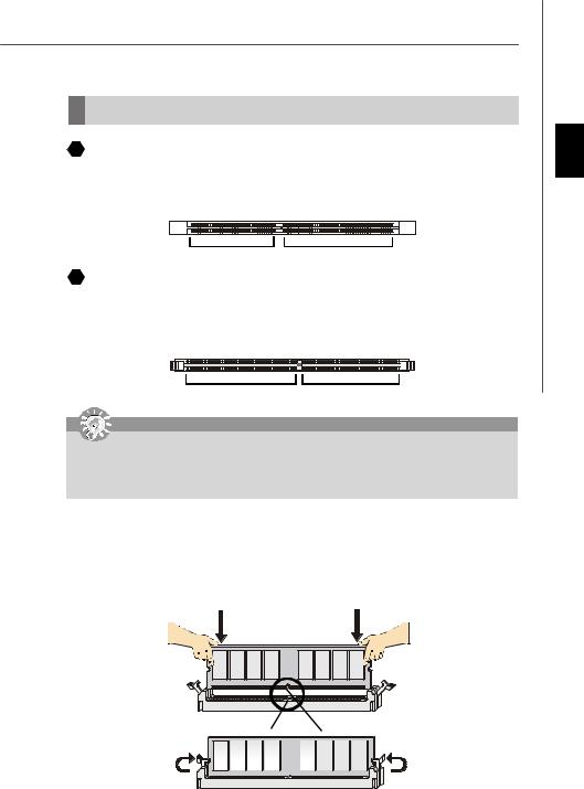
2  DDR
DDR
Specification : 184-pin, 2.5v.
Single channel definition : All DIMM slots are GREEN color.
Dual channels definition : DIMM slot(s) on Channel A are marked in GREEN color. DIMM slot(s) on Channel B are marked in Purple color.
40x2=80 pin |
52x2=104 pin |
 3
3  DDRII
DDRII
Specification : 240-pin, 1.8v.
Single channel definition : All DIMM slots are GREEN color.
Dual channels definition : DIMM slot(s) on Channel A are marked in GREEN color. DIMM slot(s) on Channel B are marked in Orange color.
64x2=128 pin |
56x2=112 pin |
Important
-DDRII modules are not interchangeable with DDR and the DDRII standard is not backward compatible, you should always install DDRII memory module in the DDRII DIMM slot and install DDR memory module in the DDR DIMM slot.
-In dual-channel mode, make sure that you install memory modules of the same type and density in different channel DDR DIMM slots.
-To enable successful system boot-up, always insert the memory modules into the DIMM1 first.
Installing DDR/ DDRII Modules
You can find the notch on the memory modules and the volt on the DIMM slots whetherDDR orDDRII. Follow the procedures below to install the DDR/ DDRII module properly.
1.The DDR/DDRII modules has only one notch on the center of module. The module will only fit in the right orientation.
2.Insert the memory module vertically into the DIMM slot. Then push it in until the golden finger on the memory module is deeplyinserted in the socket.
3.The plastic clip at each side of the DIMM slot will automatically close.
English
Volt |
|
|
|
|
|
Notch |
|||
|
|
|
|
|
|
|
|
|
|
|
|
|
|
|
|
|
|
|
|
|
|
|
|
|
|
|
|
|
|
|
|
|
|
|
|
|
|
|
|
En-5

 MS-7252 Mainboard
Connectors, Jumpers, Slots
 4
4 Fan Power Connectors
The fan power connectors support system cooling fan with +12V. The CPU FAN supports Smart FAN function. When connect the wire to the connectors, always take note that the red wire is the positive and should be connected to the +12V, the black wire is Ground and should be connected to GND. If the mainboard has a System Hardware Monitor chipset onboard, you must use a specially designed fan with speed sensor to take advantage of the fan control.
Control |
|
|
|
SENSOR or NC |
|
|
|
|
SENSOR |
|
|
|
+12V |
|
|
|
|
+12V |
|
|
|
GND |
|
|
|
|
|
|
|
||||||
GND |
|
|
|
|
|
|
|
|
|
|
|
SYS FAN/ NB FAN/ |
|||||
CPU FAN |
||||||||
POWER FAN |
||||||||
Important
Please referto the recommended CPU fans at AMD® official website or consult the vendors for properCPU cooling fan. Fan/heatsink with 3 or 4 pins are both available for CPUFAN.
 5
5  Floppy Disk Drive Connector (FDD connector)
The mainboard provides a standard floppy disk drive connector that supports 360K, 720K, 1.2M, 1.44M and 2.88M floppy disktypes.
 6
6 ATA133 Hard Disk Connector (IDE connector)
A IDE connector can connect a Master and a Slave drive. You can connect CD-ROM/ Hard Driver and other IDE devices. The UltraATA133 interface boosts data transfer rates between the computer and the hard drive up to 133 megabytes (MB) per second. The new interface is one-third faster than earlier record-breaking UltraATA/100 technology and is backwards compatible with the existing Ultra ATA interface.
Important
If you install two hard disks on cable, you must configure the second drive to Slave mode by setting its jumper. Refer to the hard disk documentation supplied by hard disk vendors for jumper setting instructions.
 7
7  Serial ATA Connector
SATA1.0 connector supports serialATA data rates of 150 MB/s and will be marked in ORANGE color. SATA 2.0 connector supports serial ATA data rates of 300 MB/s and will be marked in PURPLE color. Each SATA connector can connect to 1 hard disk device.
|
|
|
|
|
|
|
|
SATA 1.0 connector (Orange) |
|
|
|
|
|
|
|
|
|
Serial ATAcable |
|
|
|
|
|
|
|
SATA 2.0 connector (Purple) |
|
|
|
|
|
|
|
||
|
|
|
|
|
|
|
Take out the dust coverand connect |
|
|
|
|
|
|
|
|
|
to the hard disk devices |
Connect to SATA connector
Important
Please do not fold the Serial ATA cable into 90-degree angle. Otherwise, data loss may occur during transmission.
En-6
Installation Guide
 8
8  Front Panel Connectors
These two front panel connectors are used forelectrical connection to the front panel switches and LEDs. JFP1 is compliant with Intel® Front Panel I/O Connectivity Design Guide.
|
Reset |
HDD |
|
8 7 |
|
|
|
Switch LED |
|
Pow er |
|
||
|
|
|
|
|||
JFP1 |
9 |
1 |
Spe a |
|
JFP2 |
|
2 |
|
|||||
|
10 |
ker |
|
EL |
|
|
|
|
|
2 1 |
|
||
|
|
|
|
D |
|
|
Power Power
Switch LED
 9
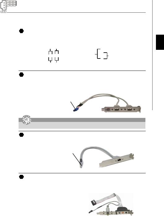
9  Front USB 2.0 Connector (Yellow)
USB 2.0 technology increases data transfer rate up to a maximum throughput of 480Mbps, which is 40 times faster than USB 1.1, and is ideal for connecting high-speed USB interface peripherals such as USB HDD, digital cameras, MP3 players, printers, modems and the like.
|
1 2 |
USB 2.0 Bracket |
|
|
(Optional) |
||
VCC |
VCC |
||
USB0- |
USB1- |
Connected to USB |
|
connector |
|||
USB0+ |
USB1+ |
||
|
|||
GND |
GND |
|
|
Key(no pin) |
USBOC |
|
|
|
9 10 |
|
Important
Note that the pins of VCC and GND must be connected correctly to avoid possible damage.
 10 IEEE 1394 Connector (Green)
The 1394 pin headerallows you to connect IEEE 1394 ports via an external IEEE1394 bracket.
|
1 2 |
TPA+ |
TPA- |
Ground |
Ground |
TPB+ |
TPB- |
Cablepower |
Cablepower |
Key(no pin) |
Ground |
|
9 10 |
Connected to 1394 connector (with foolproof design)
IEEE1394Bracket
(Optional)
 11 SPDIF-Out Connector/ SPDIF-In Connector
These two connectors are used to connect SPDIF (Sony & Philips Digital Interconnect Format) interface for digital audio transmission.
Connected to JSPDO1 or JSPDI1 is at your desire.
GND |
GND |
SPDIF_out |
SPDIF_in |
VCC |
VCC |
JSPDO1 |
JSPDI1 |
Audio-out/ SPDIF Bracket
(Optional)
English
En-7
 MS-7252 Mainboard
12 Front Panel Audio Connector |
|
|
1 2 |
|
The front panel audio connectorallows you to connect to the front panel audio and |
port1 _L |
Ground |
||
is compliant with Intel® Front Panel I/O Connectivity Design Guide. |
port1 _R |
Presence# |
||
|
|
|
port2_R |
Sense1_Return |
|
|
|
Sense_Send |
Key |
|
1 2 |
|
port2_L |
Sense2_Return |
|
|
|
910 |
|
AUD_MIC |
AUD_GND |
|
|
|
|
|
|
||
AUD_MIC_BIAS |
AUD_VCC |
13 Front Panel Audio Connector |
|
|
AUD_FPout_R |
AUD_RET_R |
|
|
|
HP_ON |
Key |
The frontpanel audio connectorallows you to connect tothe frontpanel audio and |
||
AUD_FPout_ L |
AUD_RET_L is compliant with Intel® Front Panel I/O Connectivity Design Guide. |
|||
|
9 10 |
|
|
|
Important
If you do not want to connect to the front audio header, pins 5 & 6, 9 & 10have to be jumperedin order to have signal output directed to the rear audio ports. Otherwise, the Line-Out connector on the back panel will not function.
 14
14 CD-In Connector
This connector is provided for CD-ROM audio.
L GND R
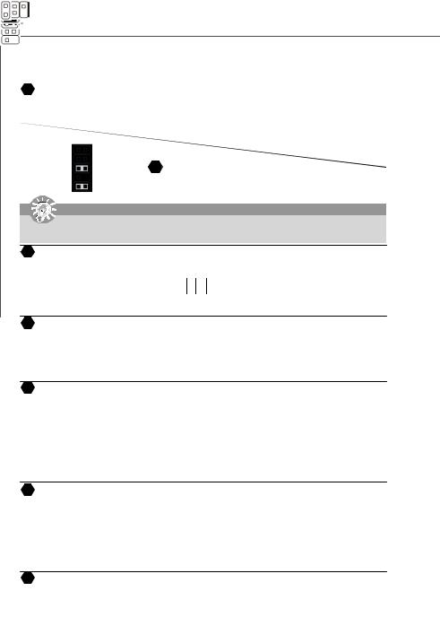
 15
15 Chassis Intrusion Switch Connector
This connector is connected to a 2-pin chassis switch. If the chassis is opened, the switch will be short. The system will record this status and show a warning message on the screen. To clear the warning, you must enter the BIOS utility and clear the record.
1CINTRU
2GND
 16
16 IrDA Infrared Module Connector
The connectorallows you to connect to IrDA Infrared module. You must configure the setting through the BIOS setup to use the IR function. It is compliant with Intel® Front Panel I/O Connectivity Design Guide.
NCVIR
C5CXT
51
62
CNrGIR uoXR dn
 17
17 Serial Port Header
The 9-pin header allows you to connect serial port via an external COM port bracket.
|
1 6 |
DCD |
DSR |
SIN |
RTS |
SOUT |
CTS |
DTR |
RI (9) |
Ground |
5 |
|
 18
18 TV-Out Connector
The TV-Out connector is for you to attach a TV-Out bracket. The TV-Out bracket offers some types of TV-Out connectors. Select the appropriate one to connect to an television and it will be able to display PC information.
14
Ground |
COMP or CVBS |
Yout |
Ground (5) |
Cout |
3 |
|
En-8

Installation Guide
 19 D-Bracket™ 2 Connector
The connector is for you to connect D-Bracket™ 2. D-Bracket™ 2 is a external USB Bracket that support both USB1.1 & 2.0 spec. It integrates four LEDs and allows users to identify system problem through 16 various combinations of LED signals. The 4 LEDs can debug all problems that fail the system, such as VGA, RAM or otherfailures. This special feature is very useful for the overclocking users. These users can use the feature to detect if there are any problems or failures.
1 2 |
|
Connected to D-Bracket™ |
|
DBR1 |
2 Connector |
|
|
DBG1 |
|
||
|
|
||
DBG2 |
DBR2 |
|
|
DBG3 |
DBR3 |
|
|
DBG4 |
DBR4 |
|
|
Key(no pin) |
NC |
|
|
9 10 |
|
|
|
|
|
|
Connected to the USB pinheader |
|
|
|
in YELLOW color |
Red |
|
Green |
|
LEDs signal |
|
Description |
LEDs signal |
D-Bracket™ 2
(Optional)
1 |
2 |
LEDs |
3 |
4 |
|
Description
1 |
2 |
System PowerON |
|
The D-LED will hang here if the |
|||
3 |
4 |
processor is damaged or not in- |
|
stalled properly. |
|||
|
|
||
1 |
2 |
EarlyChipset Initialization |
|
3 |
4 |
|
|
|
|
Memory Detection Test |
|
1 |
2 |
Testing onboard memory size. The |
|
D-LED will hang if the memorymod- |
|||
3 |
4 |
||
ule is damaged or not installed |
|||
|
|
properly. |
|
1 |
2 |
Decompressing BIOS image to RAM |
|
3 |
4 |
for fast booting. |
|
|
|||
1 |
2 |
Initializing Keyboard Controller. |
|
3 |
4 |
||
|
|||
1 |
2 |
Testing VGA BIOS |
|
This will start writing VGA sign-on |
|||
3 |
4 |
||
message to the screen. |
|||
1 |
2 |
Processor Initialization |
|
This will show information regarding |
|||
|
|
||
3 |
4 |
the processor (like brand name, sys- |
|
|
|
tem bus, etc...) |
|
1 |
2 |
Testing RTC (Real Time Clock) |
|
3 |
4 |
||
|
1
3
1
3
1
3
1
3
1
3
1
3
1
3
1
3
Initializing Video Interface
2 This will start detecting CPU clock,
4checking type ofvideo onboard. Then, detect and initializethe video adapter.
BIOS Sign On
2 This will start showing information
4about logo, processor brand name, etc...
Testing Base and Extended Memory 2 Testing base memory from 240K to
4640K and extended memory above 1MB using various patterns.
2 |
Assign Resources to all ISA. |
|
4 |
||
|
2Initializing Hard Drive Controller This will initialize IDE drive and
4 controller.
2Initializing Floppy Drive Controller This will initialize Floppy Drive and
4 controller.
2 BootAttempt
This will set low stack and boot via
4 |
INT 19h. |
|
|
||
2 |
Operating System Booting |
|
4 |
||
|
English
En-9
 Loading...