


Service Manual
Datascope
Passport
®
0070-01-0705-02_PPV srv color.indd 1 2/17/11 4:32 PM

Service Manual
Datascope
Passport
®
0070-02-0705-02_PPV srv b_w.indd 1 2/17/11 4:33 PM

CapnoLine® is a U.S. registered trademark of Oridion Medical Ltd.
f
DRYLINE
Durasensor
Edwards
FilterLine
LNCS
LNOP
Masimo SET
Max-Fast
miniMediCO
Microstream
Navigator
Nellcor
NIV Line
Oxiband
™
is a trademark of Artema Medical AB
®
is a U.S. registered trademark of Nellcor Puritan Bennett Inc.
®
is a U.S. registered trademark of Edwards Lifesciences Corp.
®
is a U.S. registered trademark of Oridion Medical Ltd.
®
is a U.S. registered trademark of Masimo Corp.
®
is a U.S. registered trademark of Masimo Corp.
®
is a U.S. registered trademark of Masimo Corp.
™
is a trademark of Nellcor Puritan Bennett Inc.
®
is a U.S. registered trademark of Oridion Medical Ltd.
2
®
is a U.S. registered trademark of Oridion Medical Ltd.
™
is a U.S. trademark of Mindray DS USA, Inc.
™
is a U.S. trademark of Nellcor Puritan Bennett Inc.
™
is a trademark of Oridion Medical Ltd.
®
is a U.S. registered trademark of Nellcor Puritan Bennett Inc.
™
OxiMax
Oxisensor
Passport V
Velcro
Viewstation OR
Windows
is a U.S. trademark of Nellcor Puritan Bennett Inc.
®
is a U.S. registered trademark of Nellcor Puritan Bennett Inc.
™
is a U.S. trademark of Mindray DS USA, Inc.
®
is a registered trademark of Velcro Industries B.V.
™
is a U.S. trademark of Mindray DS USA, Inc.
®
is a registered trademark of Microsoft Corp.
Copyright © Mindray DS USA, Inc., 2009. All rights reserved. Contents of this publication may not be reproduced in any
orm without permission of Mindray DS USA, Inc.
Passport V™ Service Manual 0070-10-0705

Table of Contents
Foreword....................................................................................................................................................... v
Warnings, Cautions, and Notes .......................................................................................................................v
Warnings ......................................................................................................................................................v
Cautions ........................................................................................................................................................ v
Notes ............................................................................................................................................................ vi
Theory of Operation .........................................................................................................1 - 1
Introduction....................................................................................................................................................1 - 1
System Connections ........................................................................................................................................1 - 2
Mounting the Patient Monitor ....................................................................................................................1 - 2
Connectors for Peripheral Devices .............................................................................................................1 - 2
Main Unit ......................................................................................................................................................1 - 3
Input System ........................................................................................................................................... 1 - 4
Output System.........................................................................................................................................1 - 4
Processing and Communications System.....................................................................................................1 - 6
Power Management System ...................................................................................................................... 1 - 6
Equipment Interface System....................................................................................................................... 1 - 8
Parameter modules ..................................................................................................................................1 - 10
Block Diagrams ................................................................................................................ 2 -1
Introduction....................................................................................................................................................2 - 1
Block Diagram................................................................................................................................................ 2 - 2
Repair Information ........................................................................................................... 3 - 1
Introduction....................................................................................................................................................3 - 1
Safety Precautions...........................................................................................................................................3 - 1
Troubleshooting Guidelines .............................................................................................................................. 3 - 2
Special Tools Required ....................................................................................................................................3 - 2
Disassembly Instructions...................................................................................................................................3 - 2
Removal of the Key Panel and Keys ...........................................................................................................3 - 3
Removal of the Front Housing Assembly .....................................................................................................3 - 4
Removal of the Main Board ......................................................................................................................3 - 5
Removal of the Inverter............................................................................................................................. 3 - 6
Removal of the LCD Panel.........................................................................................................................3 - 7
Removal of the Keyboard .........................................................................................................................3 - 8
Removal of the Alarm LED Board ...............................................................................................................3 - 9
Removal of the Encoder............................................................................................................................3 - 9
Removal of the Multi-parameter Board Assembly .........................................................................................3 - 10
Removal of the Parameter Front Panel Assembly ..........................................................................................3 - 12
Removal of the Multi-parameter board........................................................................................................3 - 13
Removal of the CO
Removal of the Masimo SpO
Removal of the Nellcor SpO
Removal of the NIBP Assembly .................................................................................................................. 3 - 15
Removal of the Local Printer Assembly........................................................................................................ 3 - 15
Removal of the Local Printer Cover (if needed).............................................................................................3 - 16
Removal of the Main Frame and Multi-parameter Board Assembly ................................................................. 3 - 16
Removal of the Speaker Assembly .............................................................................................................3 - 17
Removal of the Fan Assembly....................................................................................................................3 - 18
Removal of the CF Card Assembly............................................................................................................. 3 - 19
Removal of the Power Board .....................................................................................................................3 - 19
Removal of the Li-ion Battery Interface Board Assembly................................................................................. 3 - 21
Removal of the Interface Board Assembly ...................................................................................................3 - 23
Removal of the Wireless AP ......................................................................................................................3 - 25
Nurse Call Cable............................................................................................................................................3 - 27
Module.....................................................................................................................3 - 13
2
Module .......................................................................................................3 - 14
2
Module ........................................................................................................3 - 14
2
Passport V™ Service Manual 0070-10-0705 i

Table of Contents
P/N 8000-21-10361 ..............................................................................................................................3 - 27
Analog Output Cable ...................................................................................................................................... 3 - 27
P/N 6100-20-86360 ..............................................................................................................................3 - 27
Defib Synch Cable ..........................................................................................................................................3 - 28
P/N 6100-20-86361 ..............................................................................................................................3 - 28
Serial Port to Gas Module 3 Cable ...................................................................................................................3 - 29
P/N 0012-00-1276-XX ............................................................................................................................3 - 29
Null Modem Cable .........................................................................................................................................3 - 30
P/N 0012-00-1275-01............................................................................................................................3 - 30
Universal ECG Lead Wires ..............................................................................................................................3 - 31
P/N 0012-00-1503-XX ............................................................................................................................3 - 31
ECG Cable, 3/5-lead (ESIS and Non ESIS)........................................................................................................ 3 - 32
P/N 0012-00-1745-XX ............................................................................................................................3 - 32
12-pin 3-lead Neo ECG Trunk Cable (IEC/AHA) ................................................................................................ 3 - 32
P/N 040-000072-00 ..............................................................................................................................3 - 32
IBP Cable....................................................................................................................................................... 3 - 33
P/N 040-000052-00 ..............................................................................................................................3 - 33
P/N 040-000053-00 ..............................................................................................................................3 - 33
P/N 040-000054-00 ..............................................................................................................................3 - 33
P/N 040-000096-00 ..............................................................................................................................3 - 34
Temperature Cable .........................................................................................................................................3 - 34
1.15.1 P/N 040-000055-00 ...................................................................................................................3 - 34
P/N 040-000056-00 ..............................................................................................................................3 - 34
P/N 040-000057-00 ..............................................................................................................................3 - 35
P/N 040-000058-00 ..............................................................................................................................3 - 35
P/N 040-000091-00 ..............................................................................................................................3 - 35
P/N 040-000100-00 ..............................................................................................................................3 - 36
P/N 040-000224-00 ..............................................................................................................................3 - 36
Troubleshooting Menus....................................................................................................................................3 - 37
ECG Troubleshooting ............................................................................................................................... 3 - 37
NIBP Troubleshooting...............................................................................................................................3 - 39
Troubleshooting..............................................................................................................................3 - 40
SpO
2
Temperature Troubleshooting ....................................................................................................................3 - 42
Resp Troubleshooting ...............................................................................................................................3 - 43
IBP Troubleshooting .................................................................................................................................3 - 44
Troubleshooting ............................................................................................................................... 3 - 45
CO
2
Gas Module Troubleshooting ....................................................................................................................3 - 48
Trends Troubleshooting............................................................................................................................. 3 - 50
Remote/Local Printer Troubleshooting......................................................................................................... 3 - 50
Monitor/Display Troubleshooting ..............................................................................................................3 - 52
Remote View Troubleshooting ...................................................................................................................3 - 52
Installation Menu ............................................................................................................................................3 - 53
Installation Mode.....................................................................................................................................3 - 53
Advanced Installation Setup Menu............................................................................................................. 3 - 56
Options Menu......................................................................................................................................... 3 - 57
Trend Storage ................................................................................................................................................ 3 - 57
Software Download ........................................................................................................................................3 - 58
Isometric Drawings and Parts List ..................................................................................... 4 - 1
Introduction....................................................................................................................................................4 - 1
Top Level Assembly ......................................................................................................................................... 4 - 2
Main Unit Assembly ........................................................................................................................................4 - 4
Front Housing Sub-assembly ............................................................................................................................. 4 - 5
ii 0070-10-0705 Passport V™ Service Manual

Table of Contents
Rear Housing Sub-assembly ............................................................................................................................. 4 - 7
Main Chassis Sub-assembly .............................................................................................................................4 - 8
Interface Connector PCB Assembly....................................................................................................................4 - 10
Parameter Sub-assembly ..................................................................................................................................4 - 11
Patient Connector Sub-assembly........................................................................................................................4 - 12
NIBP Module Assembly ...................................................................................................................................4 - 13
Microstream CO
DPM CO
Masimo SpO
Nellcor SpO
Module Assembly .................................................................................................................4 - 14
2
Module Assembly............................................................................................................................ 4 - 15
2
PCB Assembly........................................................................................................................... 4 - 16
2
Module Assembly ....................................................................................................................... 4 - 17
2
Calibration Procedure ....................................................................................................... 5 - 1
Introduction....................................................................................................................................................5 - 1
Warnings and Guidelines................................................................................................................................5 - 1
Test Equipment and Special Tools Required........................................................................................................5 - 2
Services.........................................................................................................................................................5 - 2
ECG Channels Check ..............................................................................................................................5 - 3
NIBP Maintenance...................................................................................................................................5 - 4
NIBP Accuracy Test .........................................................................................................................5 - 4
NIBP Leakage Test ...........................................................................................................................5 - 5
NIBP Calibration .............................................................................................................................5 - 5
IBP Calibration........................................................................................................................................ 5 - 6
Calibration .....................................................................................................................................5 - 6
CO
2
Gas Calibration ......................................................................................................................................5 - 8
Monitor Log ............................................................................................................................................5 - 11
Verification ....................................................................................................................................................5 - 12
Initial Set-up............................................................................................................................................ 5 - 12
ECG ......................................................................................................................................................5 - 13
Initialization .................................................................................................................................... 5 - 13
Leads OFF ......................................................................................................................................5 - 13
Pacer Detect ...................................................................................................................................5 - 13
Performance Test .............................................................................................................................5 - 14
IBP 1 and IBP 2 Verification ......................................................................................................................5 - 14
Temperature Verification........................................................................................................................... 5 - 14
Verification....................................................................................................................................5 - 14
SpO
2
NIBP Verification ..................................................................................................................................... 5 - 14
Battery Operation Verification...................................................................................................................5 - 15
Operation Verification......................................................................................................................5 - 15
CO
2
Leakage Current Tests ..............................................................................................................................5 - 15
Preventative Maintenance................................................................................................. 6 - 1
User Preventative Maintenance Introduction .......................................................................................................6 - 1
Preventative Maintenance Schedule .................................................................................................................. 6 - 2
Mechanical / Physical / Visual Inspection - Annually ...................................................................................6 - 2
Visual test ............................................................................................................................................... 6 - 2
Power on test ..........................................................................................................................................6 - 2
Perform NIBP Verification and Calibration – Annually ..................................................................................6 - 2
Perform CO
Perform IBP Verification and Calibration – Annually.....................................................................................6 - 2
Perform ECG Verification – Annually.......................................................................................................... 6 - 2
Perform Verification and Gas Calibration – Annually ...................................................................................6 - 3
Temperature Perform Verification – Annually ............................................................................................... 6 - 3
SpO
2
Electrical Safety Tests – Annually ...............................................................................................................6 - 3
Verification and Calibration -- Annually...................................................................................6 - 2
2
Perform Verification – Annually ........................................................................................................6 - 3
Passport V™ Service Manual 0070-10-0705 iii

Table of Contents
Cleaning and Disinfection of the Passport V Monitor ...........................................................................................6 - 4
Care and Cleaning of SpO
Cleaning and Re-use of a Nellcor
Cleaning CO
Sensors, Adapters and Sampling Components .............................................................................. 6 - 6
2
Sensors................................................................................................................. 6 - 5
2
®
Sensor.................................................................................................. 6 - 5
Sterilization and Cleaning of Cuffs....................................................................................................................6 - 7
Reusable Cuffs with Bladders ....................................................................................................................6 - 7
Reusable Bladderless Cuffs .......................................................................................................................6 - 8
Disposable Blood Pressure Cuffs................................................................................................................6 - 8
Care and Cleaning of Gas Module...................................................................................................................6 - 9
Care and Cleaning of 3- and 5-lead ECG Cables and Leadwires .........................................................................6 - 10
Battery Replacement and Maintenance .............................................................................................................. 6 - 11
Battery Replacement ................................................................................................................................6 - 11
Battery Maintenance ................................................................................................................................ 6 - 11
Local Printer Maintenance................................................................................................................................ 6 - 12
Cleaning the Local Printer Printhead...........................................................................................................6 - 12
Local Printer Paper Replacement ................................................................................................................ 6 - 12
Care and Storage of Thermal Chart Paper..................................................................................................6 - 12
Warranty Statements.......................................................................................................................................6 - 14
USA, Canada, Mexico, and Puerto Rico.....................................................................................................6 - 14
International (excluding North America) .....................................................................................................6 - 15
Phone Numbers and How To Get Help ......................................................................................................6 - 16
Manufacturer’s Responsibility .................................................................................................................... 6 - 16
iv 0070-10-0705 Passport V™ Service Manual

Foreword Introduction
Foreword
The Passport V Service Manual is intended as a guide for technically qualified personnel
during repair and calibration procedures. This publication may have been updated to reflect
product design changes and/or manual improvements.
Warnings, Cautions, and Notes
Please read and adhere to all warnings, cautions, and notes listed here and in the
appropriate areas throughout this manual.
A WARNING is provided to alert the user to potential serious outcomes (death, injury, or
serious adverse events) to the patient or the user.
A CAUTION is provided to alert the user to use special care necessary for the safe and
effective use of the device. They may include actions to be taken to avoid effects on patients
or users that may not be potentially life threatening or result in serious injury, but about which
the user should be aware. Cautions are also provided to alert the user to adverse effects on
this device of use or misuse and the care necessary to avoid such effects.
A NOTE is provided when additional general information is applicable.
Warnings
WARNING: The Passport V operates on line voltages. Therefore, an
electric shock hazard may exist when the instrument covers
are removed. Repair and calibration procedures should only
be performed by qualified personnel who proceed with care
and follow proper servicing techniques. Warnings are given
in various chapters, as well as in other appropriate
locations.
WARNING: Internal Electrical Shock Hazard - This unit does not contain
any user-serviceable parts. Do not remove instrument
covers. Refer Servicing to qualified personnel.
WARNING: Whenever the monitor is opened for calibration or repair, a
risk (leakage) current safety check and a verification of
basic functions of all parameters should be performed
before the monitor is returned to Clinical use. See
“Verification” on page 5-12.
WARNING: Do not clean the monitor while it is powered on and/or
plugged in.
WARNING: Perform the decontamination process with the unit powered
off and the power cord removed.
Cautions
CAUTION: Calibration is not to be performed while monitoring a
patient.
CAUTION: A functional tester cannot be used to assess the accuracy of
the pulse oximeter probe or a pulse oximeter monitor.
Passport V™ Service Manual 0070-10-0705 v

Introduction Notes
CAUTION: When cleaning the monitor, do not allow cleaning solutions
CAUTION: When cleaning sensors, do not use excessive amounts of
CAUTION: Some disinfectants may cause skin irritation. Please rinse
CAUTION: Using dark colored soaks may stain the cuffs. Test a single
CAUTION: When ironing or pressing the cuffs, be aware that the
CAUTION: Disposable cuffs can be cleaned using a mild soap solution
CAUTION: Do not clean the Gas Module while it is on and/or plugged
CAUTION: The internal sampling system of the Gas Module does not
into the vent openings.
liquid. Wipe the sensor surface with a soft cloth dampened
with cleaning solution. Do not attempt to sterilize.
cuff thoroughly with water to remove any residual
disinfectants.
cuff to ensure that no damage will occur.
®
Vel cro
(162°C).
and dried with a clean cloth.
in.
need to be cleaned or sterilized. There is no reverse flow
back to the patient. If the internal sampling system is
suspected to be clogged or dirty, the module should be
serviced by an authorized service person only.
fasteners can melt at temperatures above 325°F
CAUTION: To avoid permanent damage, do not expose metal
components (e.g., pins, sockets, snaps) to disinfectants,
soaps, or chemicals.
CAUTION: Recharge batteries in the Passport V.
CAUTION: Remove the batteries if the Passport V is not likely to be
used for an extended period of time.
CAUTION: Never pull the local printer paper with force when a
recording is in process; it may cause damage to the local
printer.
CAUTION: Do not leave the local printer door open unless reloading
paper or troubleshooting.
Notes
NOTE: Unauthorized servicing may void the remainder of the
warranty. Check with the factory or with a local authorized
representative to determine the warranty status of a
particular instrument.
vi 0070-10-0705 Passport V™ Service Manual
1.0
Theory of Operation
1.1 Introduction
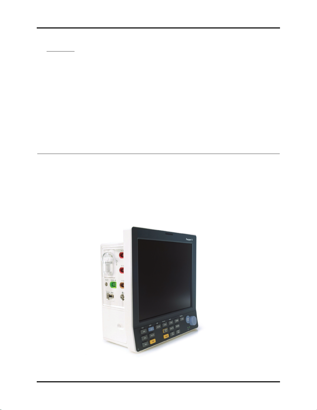
This patient monitor is intended to be used for monitoring, displaying, reviewing, storing,
and transferring of multiple physiological parameters including: ECG, respiration (Resp),
temperature (Temp), SpO
blood pressure (IBP), End tidal CO
pediatric, and neonatal patients.
, pulse rate (PR), non-invasive blood pressure (NIBP), invasive
2
value (EtCO2) and anesthetic gas (AG) of single adult,
2
FIGURE 1-1 The Passport V Monitor
Passport V™ Service Manual 0070-10-0705 1 - 1
System Connections Theory of Operation
Additional Passport V features:
• Provides audible and visual alarm indications.
• Incorporates multiple input devices such as a keypad and knob.
• Enables program upgrade over the network.
1.2 System Connections
1.2.1 Mounting the Patient Monitor
The Passport V can be mounted on a wall mount bracket, a rolling stand, or a bedrail
hook, which can be ordered optionally. Each type of mounting solution is delivered with a
complete set of mounting hardware and instructions. Refer to the documentation delivered
with the mounting hardware for instructions on assembling mounts.
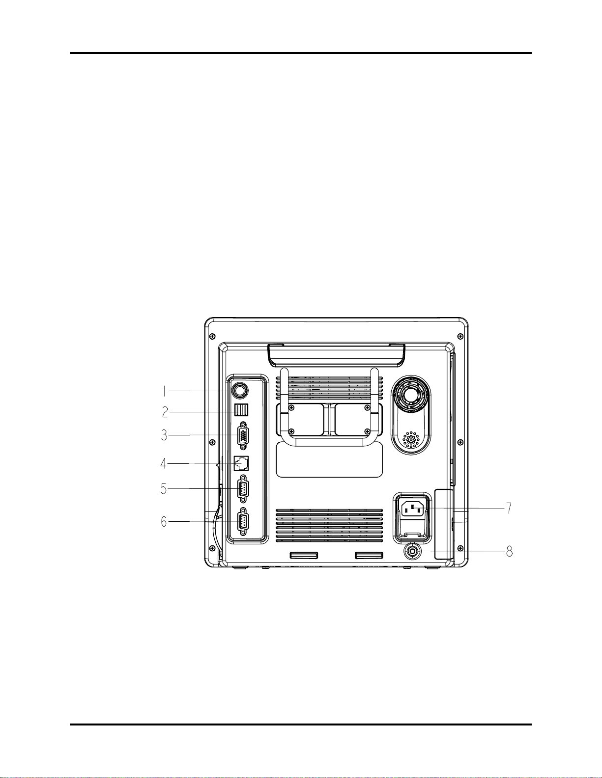
1.2.2 Connectors for Peripheral Devices
On the back of the Passport V are the connectors for peripheral devices.
FIGURE 1-2 Connectors for Peripheral Devices
1 - 2 0070-10-0705 Passport V™ Service Manual

Theory of Operation Main Unit
1. Auxiliary Output
A standard BNC connector, through which defibrillator synchronization signals, analog
output signals, and nurse call signals can be outputted, depending on how the monitor is
configured.
2. SB Connector
A connector for an external storage device.
3. VGA Connector
A connector for a standard SVGA color monitor.
4. Network Connector
An RJ45 connector, through which an Ethernet network or a PC can be connected.
5. RS232 serial port
A DB9 connector, used to connect a PC for data or a Gas Module 3, depending on how
the monitor is configured.
6. RS232 serial port
A DB9 connector, used to connect a PC for data or a Gas Module 3, depending on how
the monitor is configured.
7. AC Power Connector
A connector for an AC power source (100 to 240 VAC, 50/60Hz).
8. Equipotential lug
A connector for common ground with other equipment.
1.3 Main Unit
The Passport V consists of the following:
• Input system:
keypad, knob, and power switch.
• Output system:
LCD panel, alarm LED board, local printer, speaker, AC/battery status LEDs).
• Processing and communications system:
CPU board, Power management and interface board.
• Power management system:
battery, battery interface board, power board (AC/DC), Power management and
interface board.
• Equipment interface system:
power management and interface board, Ethernet-wireless adapter.
• Parameter modules:
multi-parameter board, CO
Additionally, the patient monitor can also connect a DPM SB storage device, a Gas
Module 3, or a PC for data transfer.
module, OEM SpO2 module, NIBP module.
2
Passport V™ Service Manual 0070-10-0705 1 - 3
Main Unit Theory of Operation
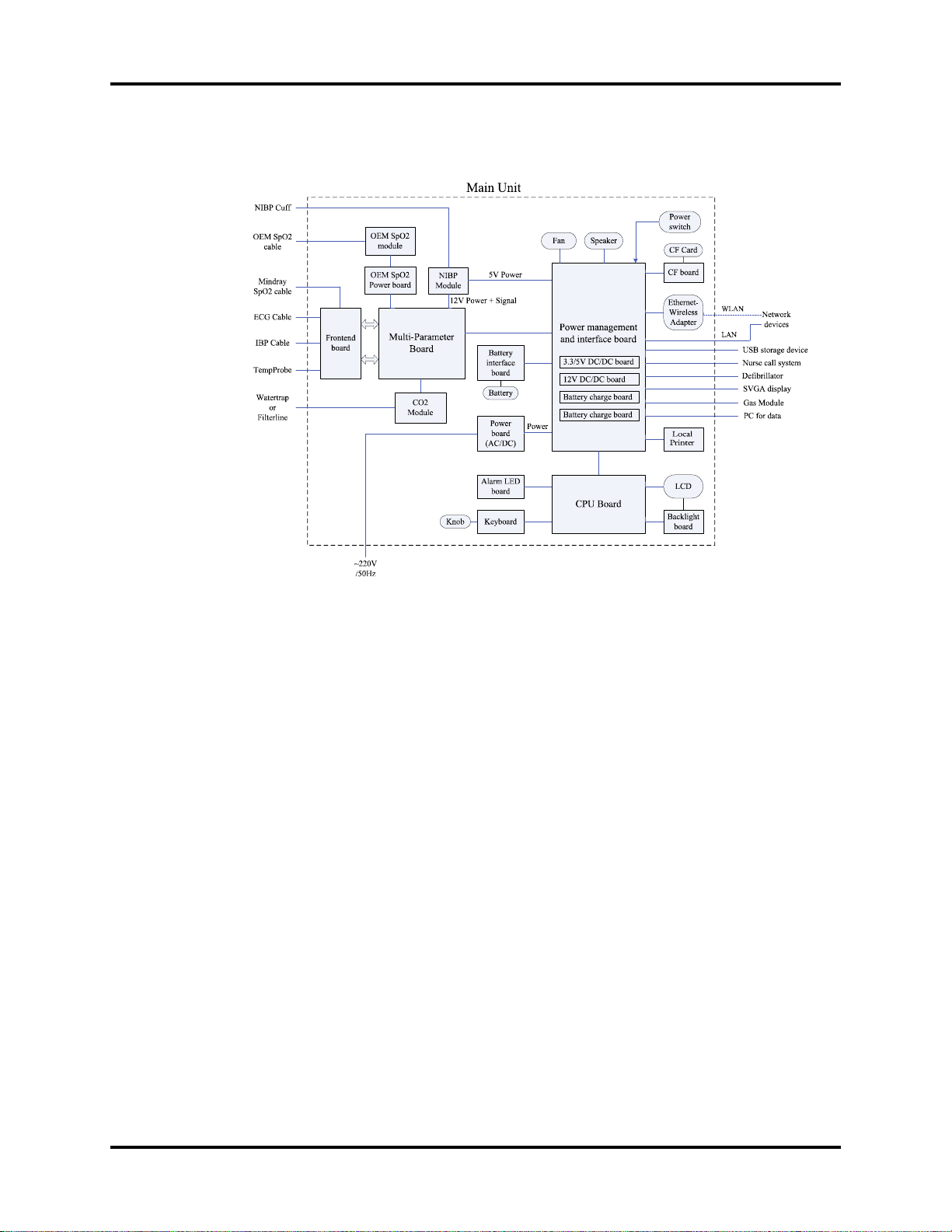
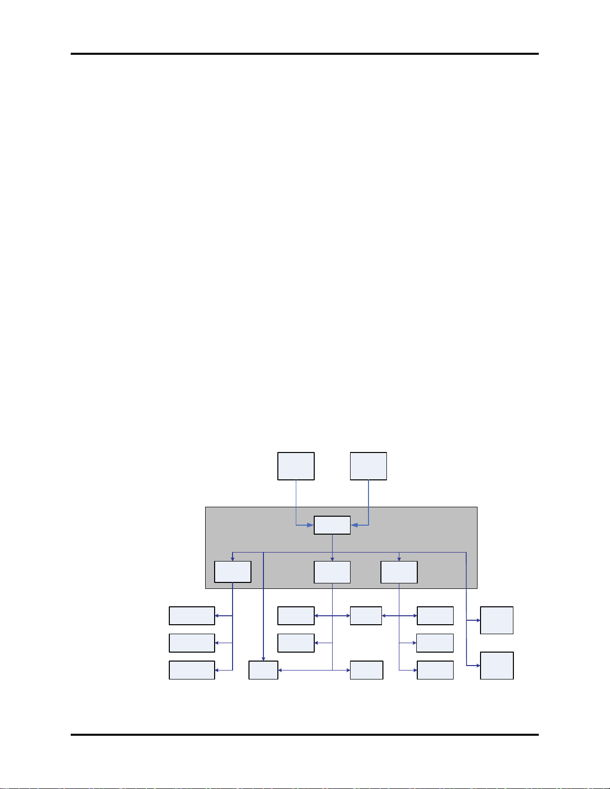
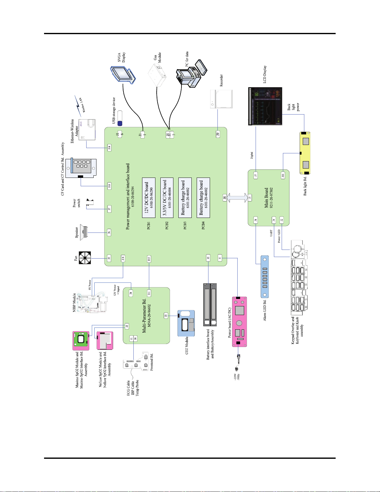
The following diagram illustrates the structure of the patient monitor.
FIGURE 1-3 Patient monitor structure
1.3.1 Input System
Keypad
The keypad, located at the lower part of the monitor’s front panel, contains 18 keys, AC
status LED and battery status LED, and also provides a connection for the knob to the CPU
board.
Knob
The knob can be pressed, or rotated either clockwise or counter-clockwise. It connects to the
keypad.
Power switch
The power switch, located at the right side of the monitor, is a single-throw rocker switch.
Pressing it will power the monitor on or off. The power switch’s status is detected by the
power management and interface board.
1.3.2 Output System
LCD Panel
The monitor uses an LCD panel with a resolution of 800x600, which runs power and gets
digital signals from the CPU board. The backlight is powered by the backlight board, which
is powered by the CPU board.
1 - 4 0070-10-0705 Passport V™ Service Manual
Theory of Operation Main Unit
Alarm Lamp
The monitor has an alarm lamp on the front panel. The alarm LED board converts the electric
signals into visual signals and then sends the visual signals to the alarm lamp through a light
pipe. The alarm lamp illuminates either red or yellow, depending on how the alarm is
configured.
Local Printer
The local printer receives data coming from the CPU board through a UART and then sends
them to the thermal print head for printing. The local printer has a hard key (starting/
stopping recordings) and a green LED on its front. It connects to the power management and
interface board.
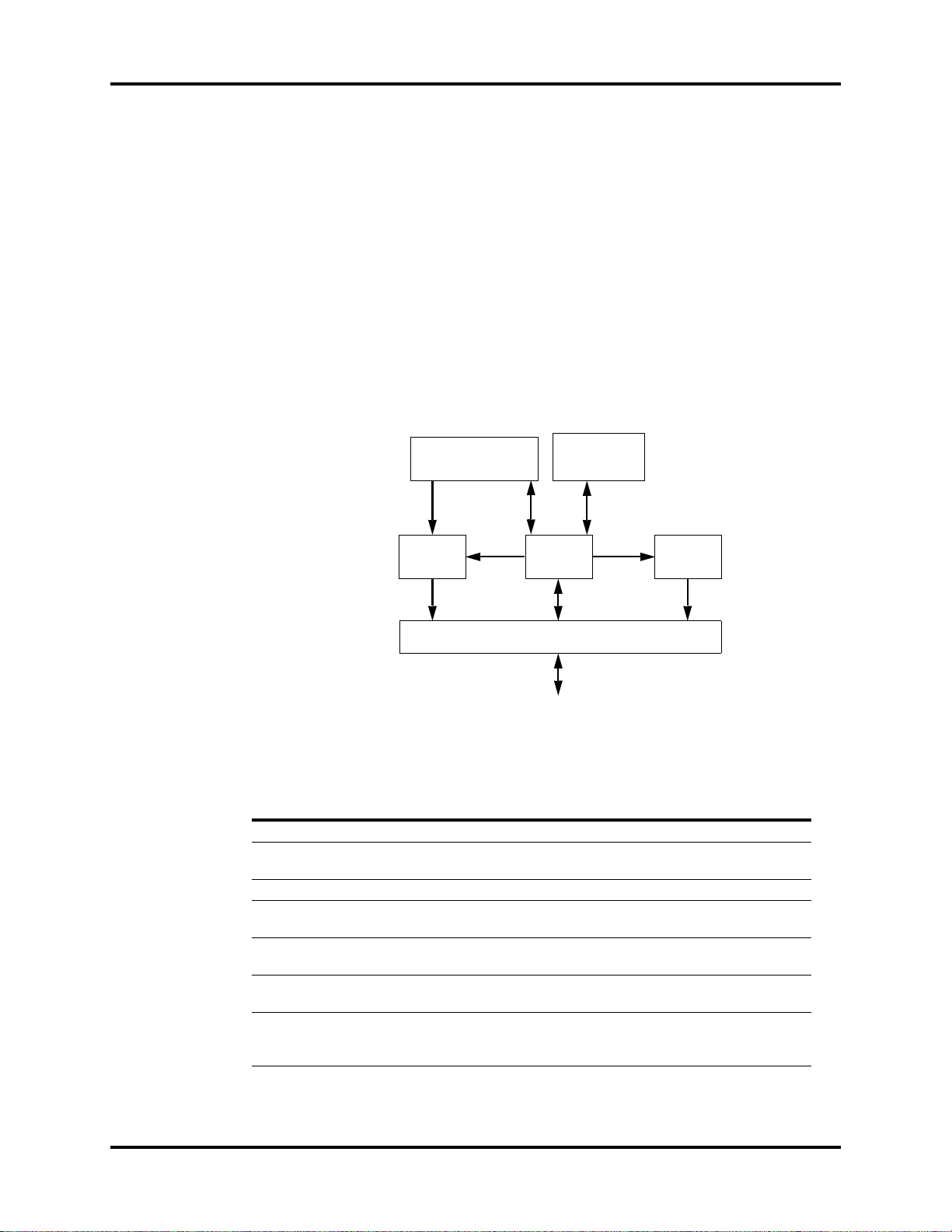
The following diagram shows its operating principle.
LOCAL PRINTER
LOCAL PRINTER
KEY BOARD
KEY BOARD
KEY & LED
INTERFACE
POWER
SUPPLY
INTERFACE
MAIN BOARD
SIGNAL
INTERFACE
POWER
MODULE
POWER
SUPPLY
CONTROL
FPC INTERFACE
THERMAL PRINT HEAD
CPU
MOTOR
CONTROL
DRIVE
CIRCUIT
FIGURE 1-4 Operating principle
MODULE DESCRIPTION
Power supply interface Introduces a DC from the CPU board.
Power module Converts the input power into voltages that fit each module and
CPU Controls the communications between modules.
Signal interface Controls the communications between the CPU board and the
Drive circuit Receives control signals from the CPU and then forwards them to
Local Printer key board Sends key commands to the CPU and receives commands from
FPC interface Sends the thermal print head information to the CPU and
then forwards them to each module.
local printer CPU.
the stepper motor.
the CPU to control the LED on the local printer.
receives commands from the CPU to control the thermal print
head.
Passport V™ Service Manual 0070-10-0705 1 - 5

Main Unit Theory of Operation
Speaker
The speaker provides sound for alarms, key strokes, heart beats, pulse, and so on. It is driven
directly by the CPU board.
AC and battery status LEDs
The AC status LED and the battery status LED, located at the keypad, are controlled by the
MCU on the power management and interface board. The driving signals come from the
power management and interface board and then go to the keypad via the CPU board.
1.3.3 Processing and Communications System
CPU board
The CPU board is the heart of the patient monitor. It implements a series of tasks including
input and output control, data storage and processing, display processing, system control,
communication management, print management, alarming, etc.
The CPU board has a CPU system comprising the CPU, FLASH, memory, real-time clock,
EEPROM, FPGA, etc. Among them, FPGA deals with audio, video, and interfacing signals.
Also, it provides interfaces to other boards, modules, and devices.
Connections and communications with other components are implemented via the CPU
board, which provides interfaces to:
• A built-in display
• The power management and interface board. Between this board and the CPU board,
the signals of USB+Network+UART+SVGA+I2C+Speaker+GPIO are communicated.
Among them, UART signals finally go to the parameter boards.
• The keypad. Between the keypad and the CPU board, there are two signal wires: one is
the UART signal wire and another is the AC power and battery status signal wire.
• The alarm LED board
Power management and interface board
The power management and interface board is a multi-functional board. It transmits UART
signals to several boards and modules (e.g., multi-parameter board, CO
SpO
module, NIBP module, local printer module, etc.).
2
1.3.4 Power Management System
Battery
The monitor uses two rechargeable lithium-ion batteries (11.1 V, 4400 mAh). The battery
compartment door is located at the left-bottom of the patient monitor. The battery power is
introduced to the power module via the battery interface board, and then processed and
distributed to each component by the power management and interface board.
module, OEM
2
Battery interface board
The battery interface board serves as an interface between the batteries and the power
management and interface board.
1 - 6 0070-10-0705 Passport V™ Service Manual
Theory of Operation Main Unit
Power board (AC/DC)
The power board (AC/DC) converts the input AC power to DC power (16.8V DC), which
then serves as the input of the power management and interface board.
Power management and interface board
This board is responsible for power management and interfaces. Power management can
perform the functions below:
1. Auto-select the DC source between the power board and the two batteries.
2. Convert the DC source into 12V, 5V, and 3.3V DC and then output them to other boards
and modules.
3. Provide over-voltage and under-voltage protection for 12V, 5V, and 3.3V DC.
4. Detect the power switch status and control power on/off.
5. Detect the battery capacity and control battery charge/discharge.
6. Control the LED for battery and AC status.
7. Control the fan and detect its running status (the complex control algorithm is
implemented via the CPU board).
8. Detect the internal temperature of the patient monitor.
On this board there are four sub-boards: 3.3V and 5V DC board, 12V DC board, and two
battery charge boards. The 3.3V and 5V DC board converts the DC source into 5V and
3.3V. The 12V DC board converts the DC source into 12V DC. Both of them have an over-
current protection mechanism. Each of the two battery charge boards controls the charging
of a battery.
The DC power system is illustrated below:
CPU board
digital circuit
Interface board
digital circuit
LCD digital
circuit
Power management
and interface board
3.3V
DC/DC
3.3V
Local
Printer
Power
board
(AC/DC)
16.8V
Knob
CF control
board
DC source
auto-select
5V
DC/DC
5V
Battery
interface
16.8V/11.1V
NIBP
Wireless
Adapter
board
11.1V
DC/DC
12V
12V
Alarm
indicator
OEM SpO2
module
CO2
module
Multi-
Parameter
board
Backlight
board
FIGURE 1-5 DC power system
Passport V™ Service Manual 0070-10-0705 1 - 7
Main Unit Theory of Operation
1.3.5 Equipment Interface System
Power management and interface board
This board is also responsible for digital interfaces.
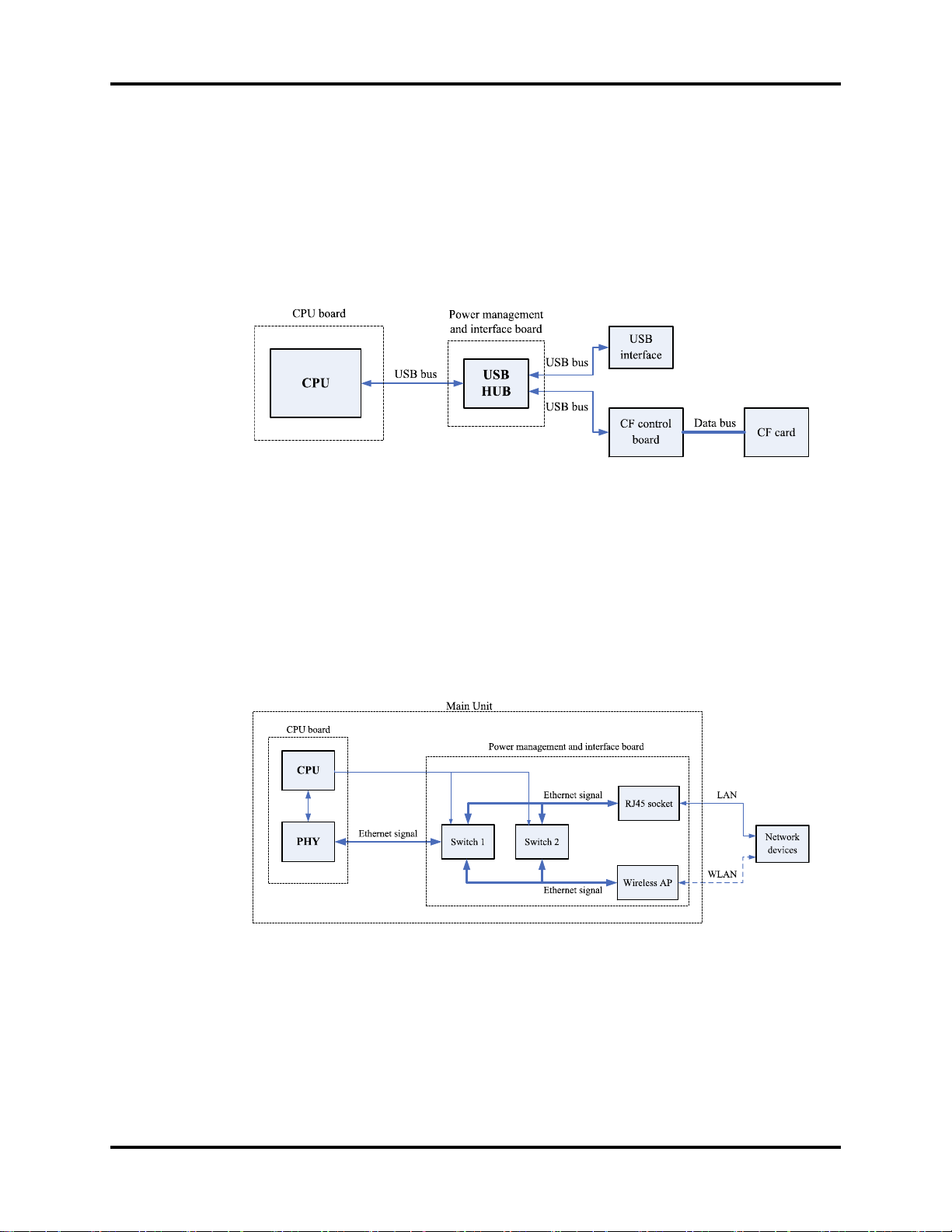
A USB HUB is located at the board. It receives USB signals from the CPU and then distributes
them to three USB ports, of which two connect the USB sockets, and the other connects the
CF control board.
FIGURE 1-6 The USB hub
This board provides connections for both wired network and wireless adapter. In the figure
below, switch 2 always stays off during normal use. The operator can switch between wired
network and wireless adapter through the software UI. Then, the CPU applies the operator’s
selection by controlling switch 1. In configuration mode, the CPU turns off switch 1 and then
turns on switch 2 so that the operator can connect a PC to the wired network to configure the
wireless adapter.
The Ethernet wireless adapter enables the patient monitor to go wireless.
FIGURE 1-7 The ethernet wireless adapter
1 - 8 0070-10-0705 Passport V™ Service Manual
Theory of Operation Main Unit
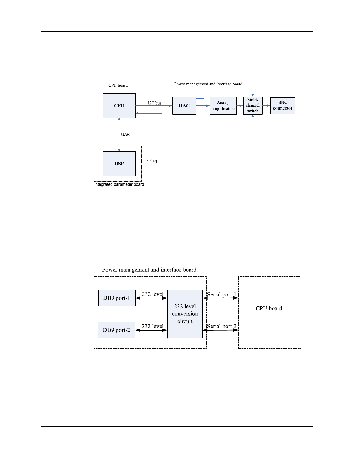
The CPU generates analog signals by controlling the DAC chip on the power management
and interface board via the I2C bus. The analog signals are transmitted to the BNC socket
via the amplifier circuit.
FIGURE 1-8 The amplifier circuit
The signal r_flag from the multi-parameter board goes to the power management and
interface board. The CPU can select the source of defibrillator synchronization signals by
controlling the output of the DAC. The signal r_flag also goes to the CPU for a self-test.
Two UART interfaces (serial port 1 and serial port 2) from the CPU board are extended as
two RS232-level ports via the power management and interface board. Both interfaces can
be configured to accommodate a PC for data or an AG module.
FIGURE 1-9 The serial ports
Passport V™ Service Manual 0070-10-0705 1 - 9

Main Unit Theory of Operation
1.3.6 Parameter modules
Multi-Parameter board
The multi-parameter board incorporates multiple parameters, such as ECG, RESP, DPM
SPO
, 2-channel IBP, TEMP, etc. Details include the following:
2
• The multi-parameter board employs a high-speed DSP, making digital filtering, arrhythmia
analysis, and ST analysis faster and more effective.
• The DSP is in charge of 3- and 5-lead ECG monitoring, arrhythmia and ST analysis, RESP
monitoring, and communicating with the CPU board.
• The multi-parameter board also employs an MCU, which supports 1-channel temperature
measurement, DPM SpO
measurement data to the DSP.
• Respiration rate is monitored using the impedance method and can only be measured
with two ECG leads.
• The multi-parameter board integrates the DPM SpO2 circuit. If a monitor is configured
with an OEM SpO
CO2 Module
, and 2-channel IBP measurement. The MCU transfers all the
2
module, then DPM SpO2 functions are overridden.
2
• There are two types of CO2 modules: DPM CO2 and Microstream CO2.
• The DPM CO2 module measures the CO2 concentration using the NDIR technology. It
performs a zero calibration periodically to ensure accurate measurements for a long
period of time. An appropriate compensation can be applied according to the patient
environment, thus preventing measurements from being influenced by interfering gases.
• The Microstream CO
module ensures that measurements will not be affected by other
2
gases and the accuracy can be maintained without any gas compensation. Additionally,
the module has a very low sample flow rate, reducing its effect on the patient and the
environment to a minimum.
OEM SpO
There are two types of OEM SpO
Module
2
modules: Masimo-2013 SpO2 module and Nellcor SpO2
2
module.
An isolation power board is attached to each of them and used to isolate the DC power and
the UART signal of the OEM SpO
modules from other circuits in the main unit. The UART
2
signal comes from the CPU board and passes through the power management and interface
board.
1 - 10 0070-10-0705 Passport V™ Service Manual
Theory of Operation Main Unit
NIBP Module
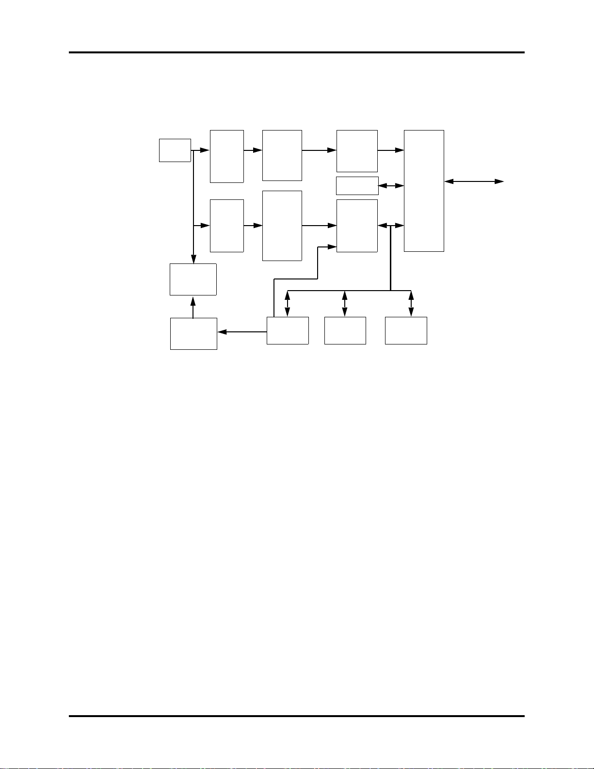
The figure below shows the NIBP module parameter board diagram.
CUFF
MANIFOLD
VALVES
AND PUMP
PRESSURE
SENSOR
FOR
PROTECT
PRESSURE
SENSOR
PRESSURE
SIGNAL
AMPLIFIER
CIRCUITS
FOR
PROTECT
VALV E
CIRCUIT
PRESSURE
SIGNAL
PRESSURE
SIGNAL
AMPLIFIER
CIRCUITS
MOTOR CONTROL
FEEDBACK SIGNAL
PUMP AND
CONTROL
OVER
PRESSURE
PROTECT
CIRCUIT
WATC HDOG
A/D
CONVERTER
FLASH DRAM
CPU
ASYCHRONOUS
SERIAL
COMMUNICATION
FIGURE 1-10 The NIBP module parameter board
The Passport V calculates NIBP values using the oscillometric method of noninvasive blood
pressure measurement. These measurements correspond to comparisons with auscultatory
values, measured using the fifth Korotkoff sound within ANSI/AAMI SP10 standards for
accuracy.
Passport V™ Service Manual 0070-10-0705 1 - 11

Main Unit Theory of Operation
This page intentionally left blank.
1 - 12 0070-10-0705 Passport V™ Service Manual

2.0
Block Diagrams
2.1 Introduction
The Block Diagrams indicate the internal organization of the instrument. The block diagrams are used to
gain both familiarity with the instrument and to locate malfunctioning PC boards as readily as possible.
DESCRIPTION PART NUMBER
NIBP Module 6100-30-86329
Masimo SpO
Nellcor SpO
Microstream CO
DPM CO
Power board (AC/DC) 9211-30-87311
Alarm LED Board 9211-30-87306
Battery interface board assembly 9211-30-87331
Keypad Overlay 6100-20-86264-XX or
Keypad 6100-20-86265-XX
Main board 9211-20-87303
Power management and interface board 6100-20-86294
Back light board 022-000001-00
LCD Display 0000-10-11092
Local Printer 6101-30-46619
Wireless AP Module 6100-30-86332
CF card assembly 6100-30-86330
Power Switch with Cable Assembly 6100-21-86306
Speaker 020-000001-00
Fan Assembly 6100-21-86315
Module 6100-30-86335
2
Module 6100-30-86336
2
Module 6100-30-86333
2
Module 6100-30-86334
2
6100-20-86341-XX
NOTE: See Isometric Drawings and Parts List for a complete list of
Part Numbers.
Passport V™ Service Manual 0070-10-0705 2 - 1
Block Diagram Block Diagrams
FIGURE 2-1 Passport V Block Diagram
2.2 Block Diagram
2 - 2 0070-10-0705 Passport V™ Service Manual

3.0
Repair Information
3.1 Introduction
This chapter provides the necessary technical information to perform repairs on the
Passport V. The most important prerequisites for effective troubleshooting are a thorough
understanding of the instrument functions as well as understanding the theory of operation.
3.2 Safety Precautions
In the event the instrument covers are removed, observe the following warnings and
guidelines.
1. Do not short component leads together.
2. The instrument covers must not be removed by anyone other than qualified technical
personnel who have received supplementary instructions regarding maintenance of
medical equipment or have equivalent experience in this area.
WARNING: Internal Electrical Shock Hazard - This unit does not contain
any user-serviceable parts. Do not remove instrument
covers. Refer Servicing to qualified personnel.
WARNING: Whenever the monitor is opened for calibration or repair, a
risk (leakage) current safety check and a verification of
basic functions of all parameters should be performed
before the monitor is returned to Clinical use. See
“Verification” on page 5-12.
Passport V™ Service Manual 0070-10-0705 3 - 1

Troubleshooting Guidelines Repair Information
3.3 Troubleshooting Guidelines
1. Identify the problem
Due to the wide variety of potential symptoms, certain problems may be more subtle
than others. One approach to troubleshooting is to set up the instrument as described in
Chapter 5.0. Following the guidelines of the tests will help determine the problem if one
exists.
2. Avoid shorting component leads
During repair procedures, it can become tempting to make a series of quick
measurements. Always turn the power off before connecting and disconnecting the test
leads and probes. The accidental shorting of leads can easily stress the components and
cause a second failure (aside from the safety risk).
3. Use the Proper equipment
The equipment listed below is suggested to fulfill a wide range of troubleshooting
requirements. It is imperative to use the designated equipment in order to ensure proper
results of any and all test procedures.
4. Clean up the repair area
After any repair, especially after any soldering or desoldering, clean off the repair area
with alcohol and a stiff brush. This will remove any residual solder flux, in turn allowing
the instrument to return to its original appearance.
3.4 Special Tools Required
• Digital Voltmeter
• Digital Mercury Manometer – 0 to 300 mmHg
• Safety Analyzer
• Patient Simulator
• Test Chamber / Dummy Cuff (P/N 0138-00-0001-01 (700 cc) or -03 (500 cc))
• Desktop PC or notebook PC.
• Microsoft Windows 2000/XP operating system
• Intel Pentium CPU, above 500MHz
• Above 128M memory
• At least one network card and at least one USB port
• CAT-5 crossover cable
• USB cable or DPM SB storage device
3.5 Disassembly Instructions
Before disassembling the unit, perform the following:
• Power down the unit and remove the line cord.
• Remove all cable assemblies from the left side, right side, and rear of the unit.
• Remove any batteries that were installed.
• Perform all work on a properly grounded ESD workstation.
3 - 2 0070-10-0705 Passport V™ Service Manual
Repair Information Disassembly Instructions
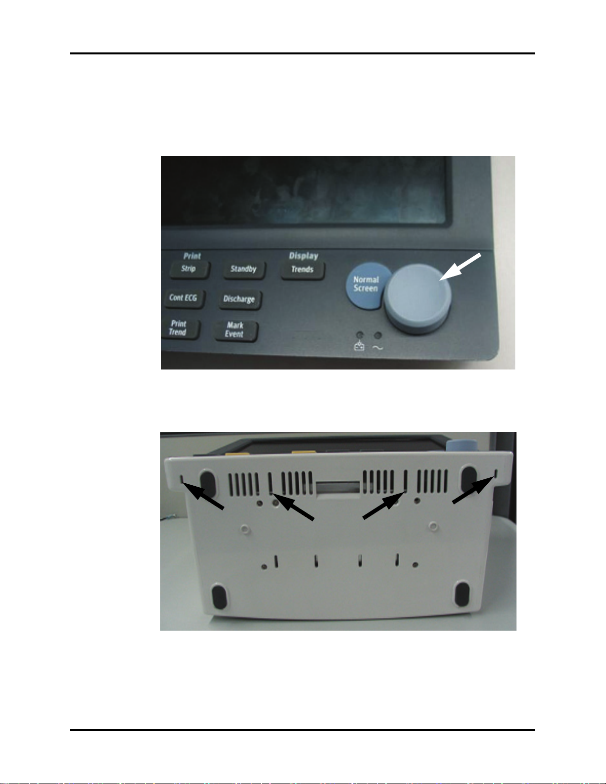
3.5.1 Removal of the Key Panel and Keys
1. Place the unit on a protective surface.
2. Carefully remove the knob with a pair of pliers that have protection on the jaws. Some
pliers may damage the knob.
FIGURE 3-1 Remove the knob
3. Release the key panel’s four clips from the bottom of the unit with a flat-bladed
screwdriver.
FIGURE 3-2 Release the key panel clips
4. Remove the key panel from the front.
5. Remove the keys and place to the side with the key panel.
Passport V™ Service Manual 0070-10-0705 3 - 3
Disassembly Instructions Repair Information
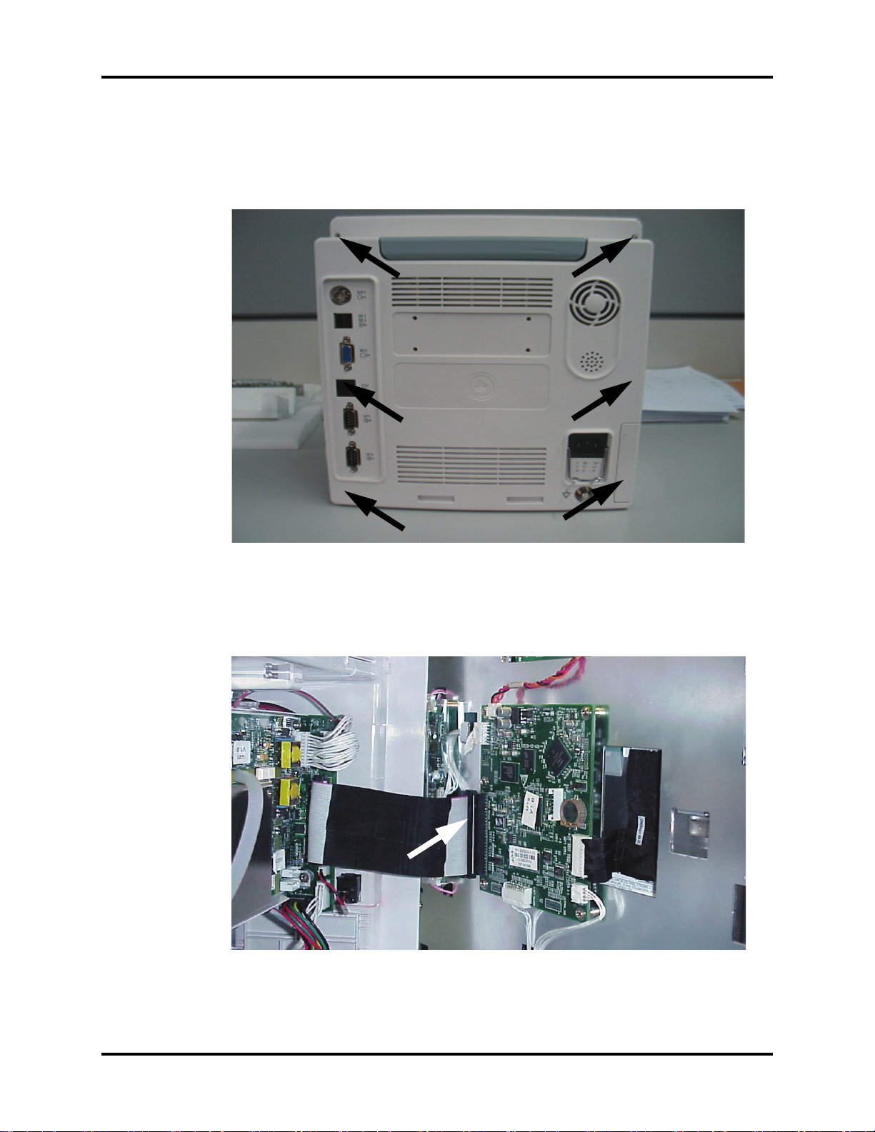
3.5.2 Removal of the Front Housing Assembly
1. Place the unit face down on a protective surface.
2. Remove the six screws from the rear of the unit.
FIGURE 3-3 Remove the screws from the rear of the unit
3. Turn the unit over and carefully separate the front housing assembly and rear housing
assembly.
4. Disconnect the 50-pin ribbon cable from the front housing assembly.
FIGURE 3-4 Disconnect the ribbon cable from the front housing assembly
5. Remove the front housing assembly.
3 - 4 0070-10-0705 Passport V™ Service Manual
Repair Information Disassembly Instructions
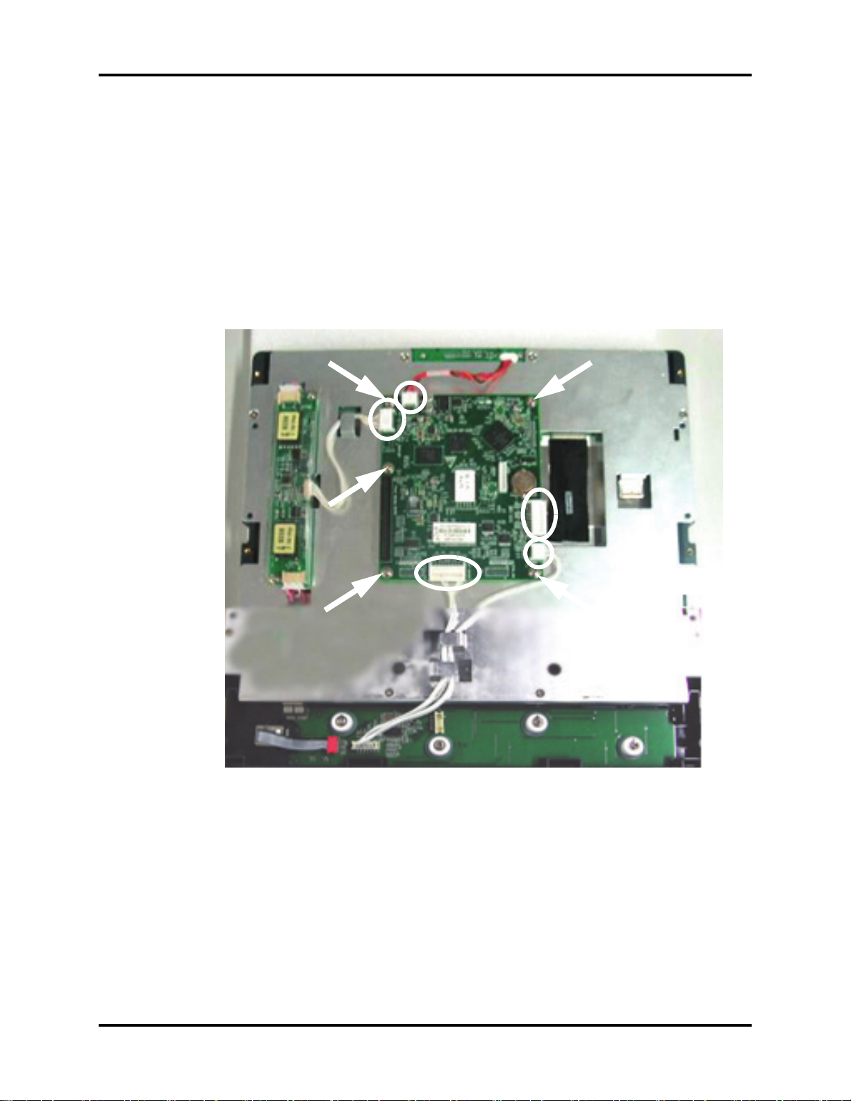
3.5.3 Removal of the Main Board
1. Remove the front housing assembly as stated in “Removal of the Front Housing
Assembly” on page 3-4.
2. Remove the keyboard cable.
3. Remove the inverter cable.
4. Remove the LCD panel cable.
5. Remove the alarm LED board cable.
6. Remove the five screws that secure the main board to the front housing bracket.
7. Remove the main board carefully.
FIGURE 3-5 Remove the main board
Passport V™ Service Manual 0070-10-0705 3 - 5
Disassembly Instructions Repair Information
3.5.4 Removal of the Inverter
1. Remove the front housing assembly as stated in “Removal of the Front Housing
Assembly” on page 3-4.
2. Remove the inverter cable.
3. Remove the two backlight board cable from the inverter.
4. Remove the two screws that secure the inverter to the front housing bracket.
5. Remove the inverter carefully.
FIGURE 3-6 Remove the inverter
3 - 6 0070-10-0705 Passport V™ Service Manual
Repair Information Disassembly Instructions
3.5.5 Removal of the LCD Panel
1. Remove the front housing assembly as stated in “Removal of the Front Housing
Assembly” on page 3-4.
2. Remove the two backlight board cables from the inverter.
3. Remove the keyboard cable.
4. Remove the alarm LED board cable.
5. Remove the LCD panel cable.
6. Remove the eight screws that secure the front housing bracket.
7. Remove the front housing bracket and place to the side.
FIGURE 3-7 Remove the LCD panel
Passport V™ Service Manual 0070-10-0705 3 - 7

Disassembly Instructions Repair Information
8. Remove the four screws that secure the LCD panel.
9. Remove the LCD panel carefully.
FIGURE 3-8 Remove the LCD panel
3.5.6 Removal of the Keyboard
1. Remove the front housing assembly as stated in “Removal of the Front Housing
Assembly” on page 3-4.
2. Remove the keyboard cable.
3. Remove the encoder cable.
4. Remove the four screws that secure the keyboard to the front housing.
5. Remove the four keyboard pads and four silica washers.
6. Release the clip on the right side of the keyboard and remove the keyboard carefully.
FIGURE 3-9 Remove the Keyboard
3 - 8 0070-10-0705 Passport V™ Service Manual

Repair Information Disassembly Instructions
3.5.7 Removal of the Alarm LED Board
1. Remove the front housing assembly as stated in “Removal of the Front Housing
Assembly” on page 3-4.
2. Remove the alarm LED board cable.
3. Remove the two screws that secure the board to the front housing.
4. Remove the alarm LED board and light conducting pipe carefully.
FIGURE 3-10 Remove the alarm LED board
3.5.8 Removal of the Encoder
1. Remove the front housing assembly as stated in “Removal of the Front Housing
Assembly” on page 3-4.
2. Remove the encoder cable from the keyboard.
FIGURE 3-11 Disconnect the encoder cable
Passport V™ Service Manual 0070-10-0705 3 - 9

Disassembly Instructions Repair Information
3. Carefully remove the knob with a pair of pliers that have protection on the jaws. Some
pliers may damage the knob.
4. Remove the nut that secures the encoder.
5. Remove the encoder carefully.
FIGURE 3-12 Remove the encoder
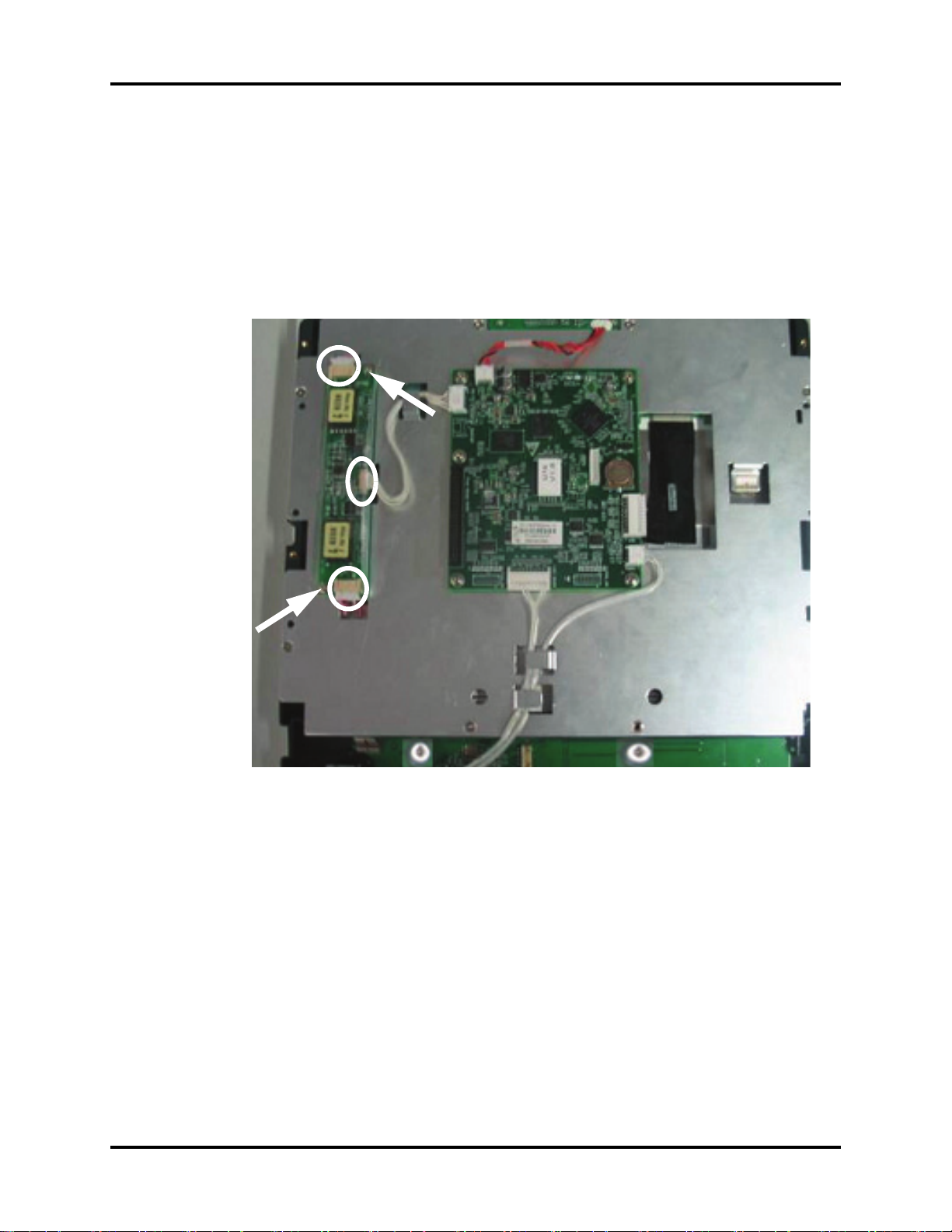
3.5.9 Removal of the Multi-parameter Board Assembly
1. Remove the front housing assembly as stated in “Removal of the Front Housing
Assembly” on page 3-4.
2. Disconnect the 50-pin ribbon cable from the interface board.
3. Disconnect the cable from J15 of the interface board.
4. Disconnect the NIBP communication cable from the interface board.
FIGURE 3-13 Disconnect the cables from the multi-parameter board
3 - 10 0070-10-0705 Passport V™ Service Manual

Repair Information Disassembly Instructions
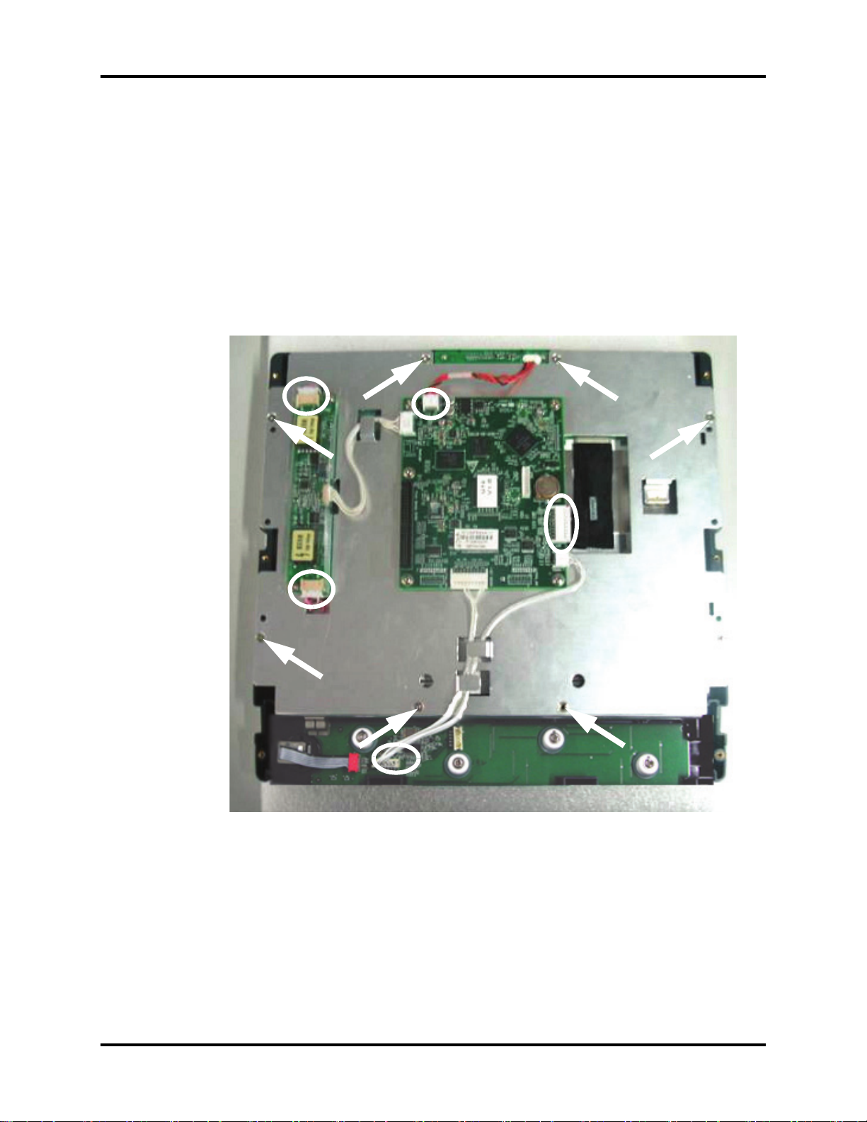
5. Remove the four screws that secure the assembly to the rear housing and main frame.
6. Disconnect the CO
tubing and cable from the multi-parameter board assembly (if CO2
2
module is configured).
7. Remove the multi-parameter board assembly carefully.
FIGURE 3-14 Remove the multi-parameter board assembly
Passport V™ Service Manual 0070-10-0705 3 - 11

Disassembly Instructions Repair Information
3.5.10 Removal of the Parameter Front Panel Assembly
1. Remove the multi-parameter board assembly as stated in “Removal of the Multi-
parameter Board Assembly” on page 3-10.
2. Unplug the tubing from the NIBP connector.
FIGURE 3-15 Unplug the tubing from the NIBP connector
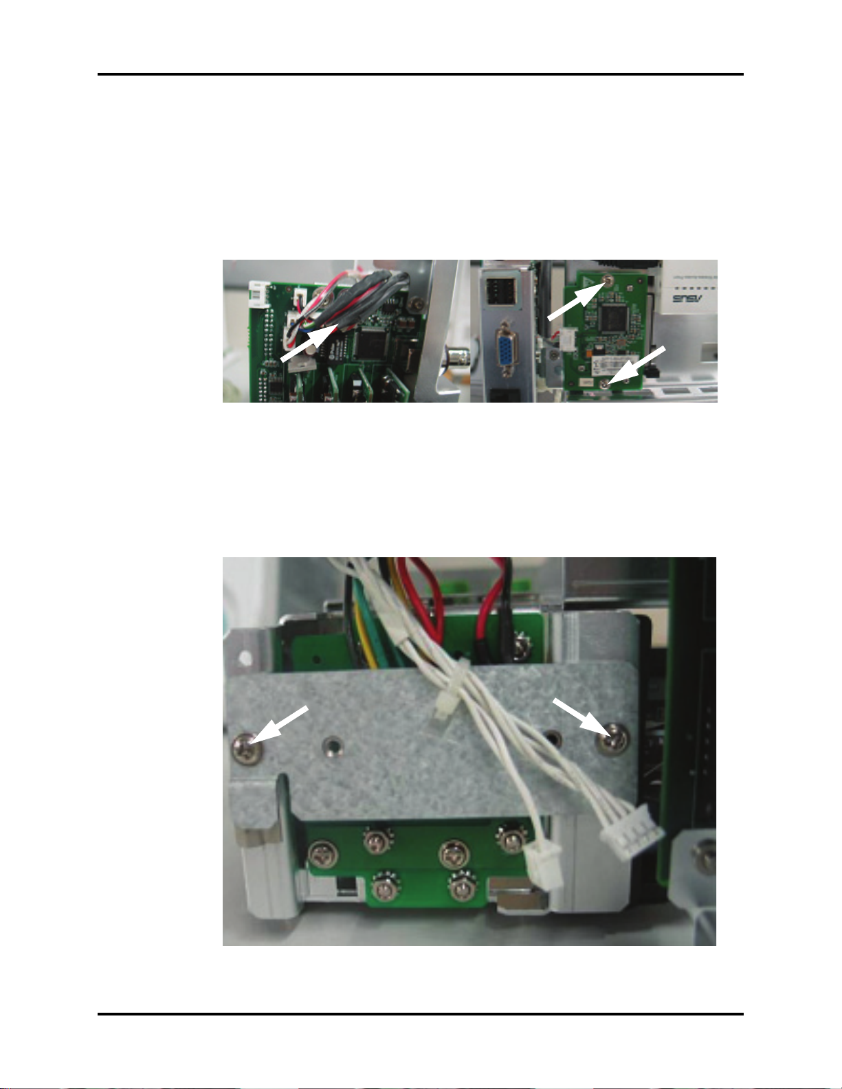
3. Unfasten the two screws that secure the SpO
connector and then remove the connector
2
(if Masimo or Nellcor SpO2 module is configured).
FIGURE 3-16 Masimo SpO
2
FIGURE 3-17 Nellcor SpO
4. Remove the three screws that secure the parameter front panel.
5. Remove the parameter front panel.
2
FIGURE 3-18 Remove the parameter front panel
3 - 12 0070-10-0705 Passport V™ Service Manual

Repair Information Disassembly Instructions
3.5.11 Removal of the Multi-parameter board
1. Remove the parameter front panel assembly as stated in “Removal of the Parameter
Front Panel Assembly” on page 3-12.
2. Remove the three screws that secure the multi-parameter board.
3. Remove the multi-parameter board.
FIGURE 3-19 Remove the multi-parameter board
3.5.12 Removal of the CO2 Module
1. Remove the multi-parameter board assembly as stated in “Removal of the Multi-
parameter Board Assembly” on page 3-10.
2. Remove the two screws that secure the module to the main frame.
3. Remove the CO
FIGURE 3-20 DPM CO2 FIGURE 3-21 Microstream CO
module.
2
2
4. Remove the water trap connector assembly or microstream CO
assembly from the parameter front panel assembly (if necessary).
Passport V™ Service Manual 0070-10-0705 3 - 13
connector fixture
2

Disassembly Instructions Repair Information
3.5.13 Removal of the Masimo SpO2 Module
1. Remove the multi-parameter board assembly as stated in “Removal of the Multi-
parameter Board Assembly” on page 3-10.
2. Disconnect the SpO2 communication cable from the multi-parameter board.
3. Cut the tie of flexible cable.
4. Unfasten the screw that secures the Masimo SpO2 module to the multi-parameter board
installation frame.
5. Unfasten the two screws that secure the Masimo SpO2 connector.
6. Remove the Masimo SpO2 module.
FIGURE 3-22 Remove the Masimo SpO2 module
3.5.14 Removal of the Nellcor SpO2 Module
1. Remove the multi-parameter board assembly as stated in “Removal of the Multi-
parameter Board Assembly” on page 3-10.
2. Disconnect the SpO2 communication cable from the multi-parameter board.
3. Cut the tie of flexible cable.
4. Unfasten the screw that secures the Nellcor SpO
installation frame.
5. Unfasten the two screws that secure the Nellcor SpO2 connector.
6. Remove the Nellcor SpO2 module.
module to the multi-parameter board
2
FIGURE 3-23 Remove the Nellcor SpO
3 - 14 0070-10-0705 Passport V™ Service Manual
module
2

Repair Information Disassembly Instructions
3.5.15 Removal of the NIBP Assembly
1. Remove the multi-parameter board assembly as stated in “Removal of the Multi-
parameter Board Assembly” on page 3-10.
2. Unplug the tubing from the NIBP gas nipple.
3. Disconnect the NIBP communication cable from the NIBP board.
4. Unfasten the screws that secure the NIBP assembly to the multi-parameter board
installation frame.
5. Remove the NIBP assembly.
FIGURE 3-24 Remove the NIBP assembly
3.5.16 Removal of the Local Printer Assembly
1. Remove the two screws that secure the local printer.
2. Release the two clips and pull out the local printer.
FIGURE 3-25 Remove the local printer assembly
3. Disconnect the local printer cable.
4. Remove the local printer.
Passport V™ Service Manual 0070-10-0705 3 - 15

Disassembly Instructions Repair Information
3.5.17 Removal of the Local Printer Cover (if needed)
1. Pry up the local printer cover with a flat-bladed screwdriver.
FIGURE 3-26 Remove the local printer cover
3.5.18 Removal of the Main Frame and Multi-parameter Board Assembly
1. Remove the front housing assembly as stated in “Removal of the Front Housing
Assembly” on page 3-4.
2. Remove the local printer assembly (if installed) as stated in “Removal of the Local Printer
Assembly” on page 3-15.
3. Disconnect the power switch cable from the interface board.
4. Remove the eight screws that secure the main frame and multi-parameter board
assembly to the rear housing.
FIGURE 3-27 Remove the screws and cables from the main frame
3 - 16 0070-10-0705 Passport V™ Service Manual

Repair Information Disassembly Instructions
5. Remove the two screws that secure the main frame from the bottom.
6. Remove the main frame and multi-parameter board assembly.
FIGURE 3-28 Remove the main frame and multi-parameter board assembly
3.5.19 Removal of the Speaker Assembly
1. Remove the main frame and multi-parameter board assembly as stated in “Removal of
the Main Frame and Multi-parameter Board Assembly” on page 3-16.
2. Cut the clamp that secures the speaker cable.
3. Disconnect the speaker cable from the interface board.
FIGURE 3-29 Disconnect the speaker cable from the interface board
4. Remove the three screws that secure the speaker.
5. Remove the speaker assembly.
FIGURE 3-30 Remove the speaker assembly
Passport V™ Service Manual 0070-10-0705 3 - 17

Disassembly Instructions Repair Information
3.5.20 Removal of the Fan Assembly
1. Remove the main frame and multi-parameter board assembly as stated in “Removal of
the Main Frame and Multi-parameter Board Assembly” on page 3-16.
2. Cut the clamp that secures the fan cable.
3. Disconnect the fan cable from the interface board.
FIGURE 3-31 Disconnect the fan cable from the interface board
4. Remove the fan EVA cushion.
5. Remove the two screws that secure the fan.
FIGURE 3-32 Remove the fan assembly
6. Remove the fan.
3 - 18 0070-10-0705 Passport V™ Service Manual
Repair Information Disassembly Instructions
3.5.21 Removal of the CF Card Assembly
1. Remove the main frame and multi-parameter board assembly as stated in “Removal of
the Main Frame and Multi-parameter Board Assembly” on page 3-16.
2. Remove the two screws that secure the CF card assembly.
3. Disconnect the CF card cable.
4. Remove the CF card assembly.
FIGURE 3-33 Remove the CF card assembly
3.5.22 Removal of the Power Board
1. Remove the main frame and multi-parameter board assembly as stated in “Removal of
the Main Frame and Multi-parameter Board Assembly” on page 3-16.
2. Remove the two screws that secure the local printer connecting board and then remove the
board.
FIGURE 3-34 Remove the screws securing the local printer connecting board
Passport V™ Service Manual 0070-10-0705 3 - 19

Disassembly Instructions Repair Information
3. Disconnect the power board connecting cable from the interface board.
FIGURE 3-35 Disconnect the power board connecting cable
4. Remove the three screws that secure the power socket support from the back of the main
frame.
5. Remove the screw that secures the grounding wire.
FIGURE 3-36 Remove the screws that secure the power socket
3 - 20 0070-10-0705 Passport V™ Service Manual

Repair Information Disassembly Instructions
6. Disconnect the power socket cable from the power board.
7. Remove the four screws that secure the power board.
8. Remove the power board.
FIGURE 3-37 Remove the power board
3.5.23 Removal of the Li-ion Battery Interface Board Assembly
1. Remove the front housing assembly as stated in “Removal of the Front Housing
Assembly” on page 3-4.
2. Remove the local printer assembly (if installed) as stated in “Removal of the Local Printer
Assembly” on page 3-15.
3. Remove the two screws that secure the local printer connecting board and then remove
the board.
FIGURE 3-38 Remove the screws securing the local printer connecting board
Passport V™ Service Manual 0070-10-0705 3 - 21

Disassembly Instructions Repair Information
4. Disconnect the Li-ion battery interface board cable from the interface board.
FIGURE 3-39 Disconnect the Li-ion battery interface board cable
5. Remove the four nuts that secure the Li-ion battery interface board assembly.
6. Remove the Li-ion battery interface board assembly.
FIGURE 3-40 remove the Li-ion battery interface board assembly
3 - 22 0070-10-0705 Passport V™ Service Manual

Repair Information Disassembly Instructions
3.5.24 Removal of the Interface Board Assembly
1. Remove the multi-parameter board assembly as stated in “Removal of the Multi-
parameter Board Assembly” on page 3-10.
2. Remove the local printer assembly (if installed) as stated in “Removal of the Local Printer
Assembly” on page 3-15.
3. Disconnect the power switch cable from the interface board.
4. Remove the six screws that secure the main frame to the rear housing.
FIGURE 3-41 Remove the screws from the main frame
5. Remove the two screws that secure the main frame from the bottom.
6. Remove the main frame assembly and place to the side.
FIGURE 3-42 Remove the screws securing the main frame
7. Disconnect the Li-ion battery interface board cable from the interface board.
8. Disconnect the power cable from the interface board.
9. Disconnect the local printer cable from the interface board.
Passport V™ Service Manual 0070-10-0705 3 - 23

Disassembly Instructions Repair Information
FIGURE 3-43 Disconnect the cables from the interface board
10. Disconnect the speaker cable from the interface board.
11. Disconnect the fan cable from the interface board.
12. Disconnect the CF card cable from the interface board.
13. Disconnect the wireless AP (if installed) cable from the interface board.
FIGURE 3-44 Disconnect the cables from the interface board
14. Remove the two screws that secure the interface board assembly to the main frame.
15. Remove the interface board assembly.
FIGURE 3-45 Remove the interface board assembly
3 - 24 0070-10-0705 Passport V™ Service Manual

Repair Information Disassembly Instructions
3.5.25 Removal of the Wireless AP
1. Remove the multi-parameter board assembly as stated in “Removal of the Multi-
parameter Board Assembly” on page 3-10.
2. Remove the local printer assembly (if installed) as stated in “Removal of the Local Printer
Assembly” on page 3-15.
3. Disconnect the power switch cable from the interface board.
4. Remove the six screws that secure the main frame to the rear housing.
FIGURE 3-46 Remove the screws from the main frame
5. Remove the two screws that secure the main frame from the bottom.
6. Remove the main frame assembly.
FIGURE 3-47 Remove the screws securing the main frame
Passport V™ Service Manual 0070-10-0705 3 - 25

Disassembly Instructions Repair Information
7. Remove the nut that secures the wireless AP to the main frame.
FIGURE 3-48 Remove the nut securing the wireless AP to the main frame
8. Disconnect the wireless AP cable from the wireless AP.
9. Remove the wireless AP.
FIGURE 3-49 Disconnect the cables from the wireless AP
3 - 26 0070-10-0705 Passport V™ Service Manual

Repair Information Nurse Call Cable
3.6 Nurse Call Cable
3.6.1 P/N 8000-21-10361
FIGURE 3-50 Nurse Call Cable
3.7 Analog Output Cable
3.7.1 P/N 6100-20-86360
FIGURE 3-51 Analog Output Cable
Passport V™ Service Manual 0070-10-0705 3 - 27

Defib Synch Cable Repair Information
3.8 Defib Synch Cable
3.8.1 P/N 6100-20-86361
FIGURE 3-52 Defib Synch Cable
3 - 28 0070-10-0705 Passport V™ Service Manual

Repair Information Serial Port to Gas Module 3 Cable
3.9 Serial Port to Gas Module 3 Cable
3.9.1 P/N 0012-00-1276-XX
DESCRIPTION DASH NUMBER
12" 9-pin mini-D serial to 25-pin D-shell -01
72" 9-pin mini-D serial to 25-pin D-shell -02
FIGURE 3-53 Serial Port to Gas Module 3 Cable
Passport V™ Service Manual 0070-10-0705 3 - 29

Null Modem Cable Repair Information
3.10 Null Modem Cable
3.10.1 P/N 0012-00-1275-01
FIGURE 3-54 Null Modem Cable
3 - 30 0070-10-0705 Passport V™ Service Manual

Repair Information Universal ECG Lead Wires
3.11 Universal ECG Lead Wires
3.11.1 P/N 0012-00-1503-XX
DESCRIPTION DASH #
10 24", snap, 5-lead set, Domestic -02
11 24", snap, 3-lead set, Domestic -05
12 24", snap, 5-lead set, International -11
13 24", snap, 3-lead set, International -14
FIGURE 3-55 Universal ECG Lead Wires
Passport V™ Service Manual 0070-10-0705 3 - 31

ECG Cable, 3/5-lead (ESIS and Non ESIS) Repair Information
3.12 ECG Cable, 3/5-lead (ESIS and Non ESIS)
3.12.1 P/N 0012-00-1745-XX
FIGURE 3-56 ECG Cable, 3/5-lead (ESIS and Non ESIS)
3.13 12-pin 3-lead Neo ECG Trunk Cable (IEC/AHA)
3.13.1 P/N 040-000072-00
FIGURE 3-57 12-pin 3-lead Neo ECG Trunk Cable (IEC/AHA)
3 - 32 0070-10-0705 Passport V™ Service Manual

Repair Information IBP Cable
3.14 IBP Cable
3.14.1 P/N 040-000052-00
FIGURE 3-58 5-pin IBP Cable (IM2301, Hospira)
3.14.2 P/N 040-000053-00
FIGURE 3-59 5-pin IBP Cable (IM2302, BD)
3.14.3 P/N 040-000054-00
FIGURE 3-60 5-pin IBP Cable (IM2303, Edwards)
Passport V™ Service Manual 0070-10-0705 3 - 33

Temperature Cable Repair Information
3.14.4 P/N 040-000096-00
FIGURE 3-61 IBP Adapter Cable (5-pin to 6-pin)
3.15 Temperature Cable
3.15.1 1.15.1 P/N 040-000055-00
FIGURE 3-62 5-pin Esophageal/Rectal Temp Probe (Adult)
3.15.2 P/N 040-000056-00
FIGURE 3-63 5-pin Esophageal/Rectal Temp Probe (Pediatric/Infant)
3 - 34 0070-10-0705 Passport V™ Service Manual

Repair Information Temperature Cable
3.15.3 P/N 040-000057-00
FIGURE 3-64 5-pin Skin Temp Probe (Adult)
3.15.4 P/N 040-000058-00
FIGURE 3-65 5-pin Skin Temp Probe (Pediatric/Infant)
3.15.5 P/N 040-000091-00
FIGURE 3-66 5-pin Temp Cable for 400 Series Disposable Sensor
Passport V™ Service Manual 0070-10-0705 3 - 35

Temperature Cable Repair Information
3.15.6 P/N 040-000100-00
FIGURE 3-67 5-pin Temp Adapter Cable (5-pin to 6.35 Phone)
3.15.7 P/N 040-000224-00
FIGURE 3-68 5-pin Temp Cable for MRS Disposable Sensor (5.5 DC Jack)
3 - 36 0070-10-0705 Passport V™ Service Manual

Repair Information Troubleshooting Menus
3.16 Troubleshooting Menus
3.16.1 ECG Troubleshooting
MESSAGE/PROBLEM REASON SOLUTION
Noisy ECG traces 1 Loose or dry electrodes.
2 Defective electrode wires.
3 Patient cable or leads are
routed too close to other
electrical devices.
Excessive Electro-surgical
Interference
Muscle Noise 1 Inadequate skin
Excessive alarms: heart rate,
lead fault
ECG Noise 1 External interference.
No ECG Waveform 1 Gain set too low.
1 Wrong ECG cable used. 1 Use ESIS ECG cable with
preparation prior to
application of electrode,
tremors, tense subject,
and/or poor electrode
placement.
1 Electrodes dry
2 Alarm limits set too close
to patient's normal heart
rate.
3 R-wave wrong size.
4 Excessive patient
movement or muscle
tremor.
2 Patient movement.
2 Lead wires and patient
cable not fully or properly
inserted.
3 Cable or lead wires
damaged.
1 Apply fresh, moist
electrodes.
2Replace wires as
necessary.
3 Eliminate 60Hz
interference.
internal filter block.
NOTE: Respiration
monitoring via the
ECG electrodes will
not be available
when using an ESIS
ECG cable.
1 Repeat skin preparation
and electrode location
procedures.
2 Apply fresh, moist
electrodes.
3 Avoid areas of the torso
that are very muscular.
1 Re-prep skin and apply
fresh, moist electrodes.
2 Readjust.
3 Must have a higher
amplitude than the other
ECG waves, like the P
and T waves.
4 Reposition electrodes and
secure with tape, if
necessary.
1 Check patient.
2 Check electrode contacts
/reposition electrodes/
cable.
3 Check environment for
source of interference.
1 Readjust as required (Set
via the Size key).
2 Check for proper
insertion.
3 Check with lead
continuity tester.
Passport V™ Service Manual 0070-10-0705 3 - 37

Troubleshooting Menus Repair Information
MESSAGE/PROBLEM REASON SOLUTION
Base Line Wander 1 Patient moving
ECG Artifact 1 Electrical interference
Self Test Error 1 During power-on of the
Communication Stop 1 As the ECG module
Communication Error 1 The ECG module
ESU-Resp Off 1 The high frequency
ECG Signal Invalid 1 Connections not tight or
Pacer Rejection On 1 When Pacer Reject is set
Learning 1 Displayed when a
No Arrhythmia Detection at
Central
excessively.
2 Patient's respiration.
Electrodes dry or loose.
3 Static build up around
patient.
4 ECG Filter set to “ST” or
“Diagnose” mode.
from auxiliary devices.
2 Patient movement.
unit, if ECG module can
not self-test successfully,
this message will display.
communication stops, the
data packets sent by the
module can not be
received.
communication error. The
command can not be sent
correctly.
electrosurgery unit
interference signal is
detected.
properly secured.
2 Electrodes dry or loose.
3 Cable or lead wires
damaged.
to On.
learning cycle has been
requested for Arrhythmia
or ST.
1 Central Station does not
have arrhythmia Analysis
capability.
1 Secure lead wires and
cable to patient.
2 Reposition electrodes.
3 Re-prep skin and apply
fresh, moist electrodes.
4Check with local
biomedical personnel.
5 Set ECG Filter to
“Monitor” mode.
1 Check patient.
2 Check Electrode Contacts
/reposition electrodes/
cable.
3 Check for electrical
interference, replace
wires as necessary.
1 Power cycle unit. If
message reappears,
contact Technical
Support.
1 Contact Technical
Support.
1 Contact Technical
Support.
1 Wait until the high
frequency electrosurgery
unit interference
disappears.
1 Ensure proper
connection. (Electrode to
lead, lead to cable, cable
to monitor).
2 Re-prep skin and apply
fresh, moist electrodes.
3 Check with continuity
tester.
1 This is normal operation.
When Pace Reject is set
to Off, this message
disappears.
/
/
3 - 38 0070-10-0705 Passport V™ Service Manual

Repair Information Troubleshooting Menus
MESSAGE/PROBLEM REASON SOLUTION
ECG Channels Checking... 1 Appears when the ECG
Module is calibrating.
Initialization Error 1 During the ECG module
power-on, as the ECG
module communication
stops, system fails to
communicate with
module.
1 This is normal operation.
Turn off ECG module
calibration and the
message will be cleared.
1 Contact Technical
Support.
3.16.2 NIBP Troubleshooting
MESSAGE/ PROBLEM REASON SOLUTION
NIBP: Self Test Error 1 Failed self-test.
2 Sensor or A/D sampling
may have error.
NIBP: Communication Error 1 NIBP module
communication error. The
command can not be sent
correctly.
NIBP: System Error 1 System error. After start-
up, the inflating pump,
A/D sampling unit or
pressure sensor may have
error or the pointer may
have error when the
software is running.
2 Power supply is not stable
or circuit failure leads to
voltage error.
NIBP: Cuff Overpressure 1 The hardware
overpressure limit has
been exceeded.
2 Overpressure. The cuff
pressure exceeds 297
mmHg in ADU mode,
240 mmHg in PED mode
or 147 mmHg in NEO
mode.
NIBP: Pneumatic Leak 1 Leakage. In Pneumatic
check, air leakage is
found in hose.
NIBP: Unable to Measure 1 Unable to make
measurement after three
automatic retries.
NIBP: Reset Failed 1 Reset failed. 1 Power cycle unit.If
1 Power cycle unit. If
message reappears,
contact Technical
Support.
1 Power cycle unit. If
message reappears,
contact Technical
Support.
1 Power cycle unit. If
message reappears,
contact Technical
Support.
1 Power cycle unit.If
message reappears,
contact Technical
Support.
1 Change the cuff.
1 Check Patient.
2 Retry measurement. If
message reappears,
power cycle unit. If
message reappears,
contact Technical
Support.
message reappears,
contact Technical
Support.
Passport V™ Service Manual 0070-10-0705 3 - 39

Troubleshooting Menus Repair Information
MESSAGE/ PROBLEM REASON SOLUTION
NIBP: Retry Pump Higher 1 A measurement has been
attempted but no reading
was possible. This results
from inadequate cuff
inflation pressure.
NIBP: Retry 1 Cuff is loosely wrapped.
The cuff may be too
loosely wrapped or not
attached at all.
2 Weak signal. The pulse of
the patient may be too
1 Retry will be attempted.
2 Check that appropriate
patient size is set.
3 Pre-set initial inflation
pressure.
1 Retry will be attempted.
Check for leaks and
quality of peripheral
pulses. Decrease patient
movement. Switch cuff to
another limb.
weak or the cuff is loosely
wrapped.
3 Excessive motion. In
measurement, signals
contain motion artifact or
too much interference.
4 Time-out. Measurement
takes more than 120
seconds in ADU/PED
mode and 90 seconds in
NEO mode.
5 Retry Overpressure or
bad measurement.
NIBP: Initialization Error 1 During the IBP module
power-on, as the IBP
1 Contact Technical
Support.
module communication
stops, system fails to
communicate with
module.
NIBP: Communication Stop 1 As the Resp module
communication stops, the
1 Contact Technical
Support.
data packets sent by the
module can not be
received.
3.16.3 SpO2 Troubleshooting
MESSAGE/ PROBLEM REASON SOLUTION
: No Sensor 1 Sensor is not plugged in
SpO
2
SpO
: Sensor Off 1 Sensor may not be
2
SpO
: Interference
2
(Masimo/Nellcor Only)
to the monitor.
connected to the patient.
1 Noise detected on the
pulse signal prevents
pulse discrimination.
SpO
: Pulse Search 1 Hardware settings are
2
being adjusted in order to
discriminate a pulse
waveform.
SpO
: No Pulse (DPM/Nellcor
2
Only)
1 No detectable pulse is
measured.
3 - 40 0070-10-0705 Passport V™ Service Manual
1 Plug the sensor into the
monitor.
1 Check patient connection.
1 Decrease patient motion,
check sensor.
1 Change to site where
pulse is stronger if patient
is vasoconstricted.
2 Change or readjust
sensor if loose.
1 Check to patient
connection and patient
status.

Repair Information Troubleshooting Menus
MESSAGE/ PROBLEM REASON SOLUTION
SpO2: Failure 1 The system has detected
an unrecoverable failure
of the SpO
system.
2
1 Power cycle unit. If
message reappears,
contact Technical
Support.
SpO
: Low Perfusion
2
(Masimo/DPM only)
1 Patient perfusion is low. 1 Check to patient
connection and patient
status.
SpO
: Too Much Light
2
(Masimo/DPM only)
1 There is too much
ambient room light for the
sensor to function
1 Minimize the room light
around the patient. Check
sensor.
properly.
SpO
: Unrecognized Sensor
2
(Masimo SET Only)
SpO
: Communication Error 1 The monitor and the
2
: Board Fault
SpO
2
(Masimo Only)
SpO
: Sensor Fault 1 Defective Sensor. 1 Replace Sensor.
2
: Motion
SpO
2
(Nellcor Only)
SpO
: Weak Pulse
2
(Nellcor Only)
SpO
: Low Signal
2
(Nellcor Only)
1 The monitor does not
recognize the sensor.
1 Replace the sensor with a
recommended sensor.
1 Power cycle unit. If
SpO
modules are not
2
communicating properly.
1 Masimo SET board failed
to operate properly.
problem persists, contact
Technical Support.
1 See Proper Service Menu:
Suggestion.
1 Motion is detected. 1 Decrease patient motion,
check sensor.
1 Low pulse amplitude. 1 Contact Technical
Support.
1The SpO2 signal is too
low or too weak.
1 Check sensor placement,
move as necessary.
2 Switch limb / Notify
physician.
: Check Sensor
SpO
2
(Nellcor Only)
SpO
: Weak Signal
2
(Nellcor Only)
1The SpO2 module has
sensed a poor connection
or a bad sensor.
1The SpO2 signal is too
low or too weak.
1 Reconnect the same
sensor. If problem
persists, replace sensor.
1 Check patient.
2 Reposition sensor.
3 Change sensor.
Unable to obtain SpO
reading
2
1 Patient has poor
perfusion. Sensor not on
Patient.
2 Cables loose / not
connected.
3 Ambient light.
1 Switch limbs / Notify
physician.
2 Reapply sensor.
3 Check connections,
switch cable.
4 Switch limbs and cover
sensor with opaque
material.
No SpO
waveform 1 Waveform not selected to
2
Display.
2 Cable or sensor not
plugged in.
1 Go to the Display Setup
Menu, choose to display
Pleth in the waveform
area.
2 Check cable and sensor.
SpO
: Initialization Error 1 No response after send
2
order during
1 Contact Technical
Support.
initialization.
Passport V™ Service Manual 0070-10-0705 3 - 41

Troubleshooting Menus Repair Information
MESSAGE/ PROBLEM REASON SOLUTION
SpO2: Communication Error 1 The monitor and the
SpO
: Communication Stop 1 As the SpO2 module
2
SpO
modules are not
2
communicating properly.
communication stops, the
data packets sent by the
SpO
module can not be
2
received.
1 Contact Technical
Support.
1 Contact Technical
Support.
3.16.4 Temperature Troubleshooting
MESSAGE/ PROBLEM REASON SOLUTION
Temperature Probes not
Work in g
Temperature not displayed 1 Improper display setup.
Temp: Communication Stop 1 As the Temp module
Temp: Communication Error 1 Temp module
Temp: SelfTest Error 1 Module sends out error
Temp: Calibration Error 1 A calibration failed. 1 Restart the monitor.
Temp: Initialization Error 1 During the Temperature
1 Poor contact from probes
to body.
2 Cable not plugged in.
communication stops, the
data packets sent by the
Temp module can not be
received.
communication error. The
command can not be
send correctly.
during selftest because of
some unspecified
reasons.
module power-on, as the
Temperature module
communication stops,
system fails to
communicate with
module.
1 Check the body surface
contact at the probe tip.
2 Reposition or apply
thermoconductive gel.
1 Check display setup in
Monitor Setup Menu and
change as desired.
2 Check the cable.
1 Contact Technical
Support.
1 Contact Technical
Support.
1 Contact Technical
Support.
2 Contact Technical
Support.
1 Contact Technical
Support.
3 - 42 0070-10-0705 Passport V™ Service Manual

Repair Information Troubleshooting Menus
3.16.5 Resp Troubleshooting
MESSAGE/ PROBLEM REASON SOLUTION
Resp. Waveform Too Large 1 Scales set
Resp. Waveform Too Small 1 Patient breathing is
False Apnea Alarm 1 Apnea delay may be
No Resp. Waveform or Rate
Displayed
“CHK Lead” Message 1 Increased impedance
Resp high impedance 1 Connections not tight
“CVA” Message 1 Can be caused by
Resp: Initialization Error 1 During the Resp module
inappropriately.
shallow or patient is
turned on side.Scale set
inappropriately.
improperly set.
2 Patient may be having
frequent episodes of CVA.
3 Scale size may be too
low.
1 Respiration turned Off.
2 Patient connected using
ESIS choke cable.
3 Cable not connected.
caused by one of the
following:
2Chest hair under
electrodes.
3 Dried electrode gel.
4 Electrode off. Lead off.
5 Cracked lead wires.
6 Poor skin prep.
and/or properly secured.
2 Electrodes dry or loose.
3 Cable or lead wires
damaged.
shallow breathing or an
apnea event.
2 Patient HR and
respiratory rate identical.
power-on, as the Resp
module communication
stops, system fails to
communicate with
module.
1 Change lead selection.
2 Change Respiration
scale.
1 Change lead selection.
2 Change respiration scale.
1 Choose another apnea
delay.
2 Reposition electrodes to
better detect respirations.
3 Change Respiration
scale.
1 Turn respiration On (Off
will be displayed in Resp.
window).
2 Check that proper patient
cable is used. Use non
ESIS patient cable.
3 Check cable.
1Prep chest.
2 Change electrodes.
3 Replace electrode.
4Replace lead.
5Replace lead wires.
6 Clean and abrade skin
before applying
electrodes.
1 Ensure proper
connection. (Electrode to
lead, lead to cable, cable
to monitor).
2 Re-prep skin and apply
fresh, moist electrodes.
3 Check with continuity
tester.
1 Check the patient.
2 Adjust scales or leads if
necessary. Check the
patient.
1 Contact Technical
Support.
Passport V™ Service Manual 0070-10-0705 3 - 43

Troubleshooting Menus Repair Information
MESSAGE/ PROBLEM REASON SOLUTION
Resp: Communication Error 1 System cannot
communicate correctly
with Resp module, and
receive the error data
packets.
Resp: Communication Stop 1 As the Resp module
communication stops, the
data packets sent by the
module can not be
received.
1 Restart the monitor. If the
error still appears, please
contact Technical
Support.
1 Contact Technical
Support.
3.16.6 IBP Troubleshooting
MESSAGE/ PROBLEM REASON SOLUTION
Damped Invasive Waveform 1 Air bubbles in tubing.
2 Kinked catheter.
3 Catheter against wall of
blood vessel.
4 Blood in tubing
5 Catheter partially
occluded with clot.
IBP not Displayed / No IBP
Wav efo rm
Abnormally High or Low
readings
Sensor Off 1 The IBP sensor
Sensor Off. Cannot Zero! 1 Sensor Off. And can not
Pulsatile Pressure. Cannot
Zero!
Pressure Overrange. Cannot
Zero!
Initialization Error 1 During the IBP module
1Improper Setup.
2 Cable not plugged in
3 Transducer not
connected.
4 Stopcock turned
improperly.
5 Transducer not zeroed.
1 Transducer too HIGH or
too LOW.
disconnected from the
patient or the monitor.
zero IBP channel.
1 Input the pulsatile
pressure, can not zero IBP
channel.
1 The pressure is
overrange, can not zero
IBP channel.
power-on, as the IBP
module communication
stops, system fails to
communicate with
module.
1 Eliminate air from tubing.
2 Change position of
catheter, check patient.
3Check for leaks at
connector, flush catheter.
4 Pump pressure bag up to
300 mmHg.
5 Consult physician.
1 Check display setup in
monitor setup.
2 Check cable.
3Check transducer
connection.
4Check transducer.
5 Check and zero the
transducer.
1 Check patient adjust
transducer, re-zero.
1 Reconnect sensor, re-zero
IBP channel.
1 Reconnect sensor, re-zero
IBP channel.
1 Input the static pressure,
re-zero IBP channel.
1 Check the static pressure
value, re-zero IBP
channel.
1 Contact Technical
Support.
3 - 44 0070-10-0705 Passport V™ Service Manual

Repair Information Troubleshooting Menus
MESSAGE/ PROBLEM REASON SOLUTION
Communication Error 1 IBP communication error.
The command can not be
send correctly.
1 Power cycle unit. If
message reappears,
contact Technical
Support.
Communication Stop 1 As the IBP module
communication stops, the
data packets sent by the
IBP module can not be
1 Power cycle unit. If
message reappears,
contact Technical
Support.
received.
3.16.7 CO2 Troubleshooting
MESSAGE/ PROBLEM REASON SOLUTION
: Check Flow Rate
CO
2
(Microstream only)
CO
: Filtering Disconnected
2
(Microstream only)
CO
: Purge
2
(Microstream only)
CO
: Occlusion
2
(Microstream only)
CO
: Sensor High Temperature
2
(DPM only)
CO
: Sensor Low Temperature
2
(DPM only)
CO
: High Airway Press.
2
(DPM only)
CO
: Low Airway Press.
2
(DPM only)
CO
: High Barometric
2
(DPM only)
1 The system has detected a
high or low flow rate.
1 Check Filterline and
replace if necessary.
1 Filtering disconnected. 1 Connect Filterline to
monitor.
1 Sample line is blocked or
kinked.
1 Check sample line. Clear
blockage or kink or
replace with a new
sample line.
1 Sample line is blocked or
kinked.
1 Check sample line. Clear
blockage or kink or
replace with a new
sample line.
1 Temperature over ranges
high limit checked by
1 Check, stop using or
replace the sensor.
module.
1 Temperature over ranges
low limit checked by
1 Check, stop using or
replace the sensor.
module.
1Measurement of Flux
Sensor in module is
higher than 790 mmHg.
1 Check airway's output
and connection.
2 If problems remain, return
it to factory for
maintaining.
1Measurement of Flux
Sensor in module is less
than 400 mmHg.
1 Check airway's output
and connection.
2 If problems remain exist,
return it to factory for
maintaining.
1 Atmospheric pressure is
too high (higher than
790mmHg).
1Check the CO
2
connections, make sure
that the monitor
application site meets the
requirements, and check
for special sources that
affect the ambient
pressure.
2 Restart the monitor.
Passport V™ Service Manual 0070-10-0705 3 - 45

Troubleshooting Menus Repair Information
MESSAGE/ PROBLEM REASON SOLUTION
: Low Barometric
CO
2
(DPM only)
1 Atmospheric pressure is
too low (lower than
428mmHg).
1Check the CO
2
connections, make sure
that the monitor
application site meets the
requirements, and check
for special sources that
affect the ambient
pressure.
2 Restart the monitor.
CO
: FilterLine Error
2
(DPM only)
1 Filterline is leaked or
blocked.
1 Check if there is a leak in
the CO
sample line or
2
sample line has
the CO
2
been occluded.
: Initialization Error
CO
2
(DPM/Microstream only)
1 No response after send
order during
1 Contact Technical
Support.
initialization.
CO
: SelfTest Error
2
(DPM/Microstream only)
1 Module can not work
because of software fault,
1 Contact Technical
Support.
circuit error, etc.
CO
: Communication Error
2
(DPM/Microstream only)
CO
: Communication Stop
2
(DPM/Microstream only)
CO
: Check Airway
2
(Microstream only)
CO
: Main Board Error
2
(Microstream only)
1The monitor receives
wrong response from
CO
module.
2
1 Sending out order is
failed during work.
1 Airway Error 1 Check airway
1 Module has problems. 1 Reset the module.
1 Contact Technical
Support.
1 Contact Technical
Support.
connection.
2 Contact Technical
Support.
: Replace Scrubber &
CO
2
Pump
(Microstream only)
CO
: 15V Overrange
2
(Microstream only)
1 Module has problems. 1 Restart the monitor.
2 Contact Technical
Support.
1 Power supply to module is
out of range.
1 Check power supply.
2 Restart the monitor.
3 Contact Technical
Support.
CO
: Hardware Error
2
(DPM only)
1 Module has problems. 1 Restart the monitor.
2 Contact Technical
Support.
CO
: No Watertrap
2
(DPM only)
1 No watertrap on CO2
module
1Make sure to plug-in
water trap, and make
sure it is firmly connected
and fastened.
CO
: Temperature Overrange
2
(Microstream only)
CO
: Check Sensor
2
(Microstream only)
1 Temperature sensor
installed in the gas cell
has read temperature
value below 5 or above
70.
1 Possible Faulty sensor. 1 Replace the module.
1 Make sure the device is
not working in extreme
hot or cold condition.
Apply cooling or heating
if possible.
2 Contact Technical
Support.
3 - 46 0070-10-0705 Passport V™ Service Manual

Repair Information Troubleshooting Menus
MESSAGE/ PROBLEM REASON SOLUTION
CO2: Warming up
(DPM/Microstream only)
1The CO2 sensor has not
reached its operating
temperature.
1 It takes typically 30
seconds for the sensor to
warm up.
2 Wait for the message to
go away.
CO
: Startup
2
(DPM only)
Calibration Completed
Successfully
1The CO2 is starting up. 1 Wait for the message to
go away.
1 Calibration finished and
/
successful.
(DPM/Microstream only)
Not Ready For Calibration
(DPM/Microstream only)
1 Module in unable to
initialize calibration.
1 Repeat calibration
procedure. If problem
persists, contact Technical
Support.
CO
: Zeroing...
2
(DPM/Microstream only)
1 The device is adjusting
the sensor signal to
predefined range for
1 This is normal operation.
Wai t for m essag e to
clear.
better measurement.
CO
: Zero Failed
2
(DPM/Microstream only)
1 Signal cannot be adjusted
to predefined range
within zeroing duration.
1Check the CO
2
connections. After the
sensor's temperature
becomes stabilized,
perform a zero
calibration again. If
problem persists, contact
Technical Support.
Calibration Error
(DPM/Microstream only)
1 The actual concentration
of calibration gas applied
is in wide discrepancy
with the concentration
value entered by the user
in the Calibration dialog.
1 Make sure the
concentration value
entered is the same as the
calibration gas applied.
2 Repeat calibration
procedure. If problem
persists, contact Technical
Support.
Caused by no gas or wrong
gas concentration
(Microstream only)
1 No gas or wrong gas
concentration.
1Check the gas
connections or gas
concentration. Repeat
calibration procedure. If
problem persists, contact
Technical Support.
Caused by Measurement Error
(Microstream only)
1 Measurement Error 1 Repeat calibration
procedure. If problem
persists, contact Technical
Support.
Caused by no stable gas flow
(Microstream only)
1 No stable gas flow 1 Check the gas
connections or gas
concentration. Repeat
calibration procedure. If
problem persists, contact
Technical Support.
Passport V™ Service Manual 0070-10-0705 3 - 47

Troubleshooting Menus Repair Information
3.16.8 Gas Module Troubleshooting
MESSAGE/ PROBLEM REASON SOLUTION
GM: Agents Uncalibrated 1 Appears after an
unsuccessful calibration
attempt of the agent
sensor. The numeric data
for all agents will appear
as XXX, and the agent
waveform will be a
flatline.
GM: CO
Uncalibrated 1 Appears after an
2
unsuccessful calibration
attempt of the CO
2
sensor. The numeric data
for CO
will appear as
2
XXX, and the CO
2
waveform will be a
flatline.
GM: N
O Uncalibrated 1 Appears after an
2
unsuccessful calibration
attempt of the N
O
2
sensor. The numeric data
for N
O will appear as
2
XXX, and the N
O
2
waveform will be a
flatline.
GM: O
Uncalibrated 1 Appears after an
2
unsuccessful calibration
attempt of the O
sensor.
2
The numeric data for O
will appear as XXX, and
the O
waveform will be
2
a flatline.
GM: Agent Zero Error 1 Appears when the system
has been unable to
successfully zero the
anesthetic agent sensor.
GM: CO
Zero Error 1 Appears when the system
2
has been unable to
successfully zero the CO
sensor.
GM: N
O Zero Error 1 Appears when the system
2
has been unable to
successfully zero the N
sensor.
GM: O
Zero Error 1 Appears when the system
2
has been unable to
successfully zero the O
sensor.
1 Ensure proper gas mixture
is attached tightly and
regulator is on. Repeat
calibration procedure. If
problem persists, contact
Technical Support.
1 Ensure proper gas mixture
is attached tightly and
regulator is on. Repeat
calibration procedure. If
problem persists, contact
Technical Support.
1 Ensure proper gas mixture
is attached tightly and
regulator is on. Repeat
calibration procedure. If
problem persists, contact
Technical Support.
1 Ensure proper gas mixture
is attached tightly and
regulator is on. Repeat
2
calibration procedure. If
problem persists, contact
Technical Support.
1 Manually start zeroing
the system again. If
problem persists, contact
Technical Support.
1 Manually start zeroing
the system again. If
2
problem persists, contact
Technical Support.
1 Manually start zeroing
the system again. If
O
2
problem persists, contact
Technical Support.
1 Manually start zeroing
the system again. If
2
problem persists, contact
Technical Support.
3 - 48 0070-10-0705 Passport V™ Service Manual

Repair Information Troubleshooting Menus
MESSAGE/ PROBLEM REASON SOLUTION
GM: Cannot Zero...Retrying 1 Appears when
Passport V requests
Zeroing (either on the
automatic cycle or by a
user request) and the Gas
Module is unable to
initialize the cycle.
GM: Warming Up 1 Appears when the system
has been turned on, and
the sensors have not
reached their stable
operating temperature.
GM: Air Leak 1 Appears when the system
detects a pneumatic leak.
2 Also may appear when
the Gas Module has been
turned on without a
sample line attached.
3 Gas Module has been on
for a long period of time
without Passport V
Monitor being on.
GM: Replace Trap 1 Indicates residue build-up
on the water trap
membrane that is
decreasing airflow.
GM: Exhaust Blocked 1 Appears when the system
detects a blockage at the
exhaust gas outlet, as
indicated by an increase
in internal pressure.
GM: Failed 1 Appears when the Gas
Module detects an
unrecoverable error in its
own operation.
GM: Occlusion 1 Appears when the system
detects an obstruction in
the sampling line or the
water trap bottle is full.
GM: Pump Off 1 Appears when the system
has turned off the pump
due to a pneumatic error.
1 Allow system to retry
without intervention. If
problem persist, contact
Technical Support.
1 Wait for the message to
go away. It takes up to
five minutes for the device
to warm up.
1 Turn Gas Module and
Passport V Off.
2Install/check sample
lines, filters, water trap
and electrical
connections.
3 Turn off Gas Module. Turn
on Gas Module and
Passport V Monitor
1 Replace water trap
reservoir.
1 Remove waste gas
scavenging assembly,
check if message
disappears.Check
exhaust line for blockage
and clear if possible. If
message persists contact
Technical Support.
1 Contact Technical
Support.
1 Empty and rinse water
trap. Change water trap,
if necessary,
2 Check sampling line and
filter for blockage, clear
sampling line if possible.
Replace sampling line
and/or filter if necessary.
3 Check exhaust line for
blockage and clear if
possible. If problem
persists, contact Technical
Support.
1 Restart the pump from the
Gas Menu. If problem
persists, contact Technical
Support.
Passport V™ Service Manual 0070-10-0705 3 - 49

Troubleshooting Menus Repair Information
MESSAGE/ PROBLEM REASON SOLUTION
GM: Unknown Agent 1 Appears when the system
detects a gas that does
not match the
spectroscopic signatures
of the five known
anesthetic agents.
Sampling Error 1 Appears when a
sampling error occurs on
one or more Gas Module
channels during
calibration.
Not Ready For Calibration 1 Appears when the Gas
Module is unable to
initialize calibration.
Zeroing Error 1 Appears when the Gas
Module cannot perform a
Zeroing during
calibration.
GM: Communication Error 1 System cannot
communicate correctly
with Resp module, and
receive the error data
packets.
GM: Disconnected 1 Appears when the
Passport V cannot
detect signals being sent
by the Gas Module.
1 Use recognized agent.
1 Repeat calibration
procedure. If problem
persists, contact Technical
Support.
1 Repeat calibration
procedure. If problem
persists, contact Technical
Support.
1 Repeat calibration
procedure. If problem
persists, contact Technical
Support.
1 Restart the monitor. If the
error still appears, please
contact Technical
Support.
1Ensure Gas Module is
turned on and interface
cable is properly
connected. If problem
persists, contact Technical
Support.
3.16.9 Trends Troubleshooting
MESSAGE/ PROBLEM REASON SOLUTION
No Trends displayed 1 Trend page is scrolled. 1 Use scroll button in Trend
Patient data is missing when
power cycling unit
1 Data storage card
abnormal.
3.16.10 Remote/Local Printer Troubleshooting
MESSAGE/ PROBLEM REASON SOLUTION
Local Printer Report Appears
Totally Blank
Local Printer Door Open 1 The printer door is not
Local Printer Out Of Paper 1 Printer out of paper. 1 Replace with a new roll of
1 Thermal paper may be
installed incorrectly (upside down).
closed.
Menu to scroll to top of
Trend Menu.
1 Contact Technical
Support.
1 Remove paper and re-
install with paper feeding
off of the spool from the
bottom.
1 Close the printer door.
paper.
3 - 50 0070-10-0705 Passport V™ Service Manual

Repair Information Troubleshooting Menus
MESSAGE/ PROBLEM REASON SOLUTION
Local Printer Busy 1 Printer received multiple
Local Printer Unable To Print 1 The system has detected
Check Remote Printer 1 Remote printer is busy,
No print on Alarm 1 Alarm printing not active. 1 Go to Alarm Setting
Trends not printing 1 Print Trend not pressed.
Local Printer Comm Error 1 Thermal paper may be
Local Printer SelfTest Error 1 The printer door is not
Thermal Printhead Overheated 1 Printer out of paper. 1 Replace with a new roll of
Printer Buffer Full 1 The printer buffer is full. /
No printer selected or
available
Remote Printer Not Available 1 This message is displayed
print requests at one time.
an unrecoverable printer
failure.
disconnected, out of
paper or has a fault
condition.
2 No Trends displayed.
3 No paper.
installed incorrectly (upside down).
closed.
1 No printer selected is
available from the
network.
in the case of a printer
error.
1 Wait until the printer is
not busy.
1 Power cycle unit. If
message reappears,
contact Technical
Support.
1 Check remote printer.
Menu and set Print on
Alarm to Active, then set
Local Printer to On.
1 Press Print Trend when
trend window is open.
Use scroll feature to scroll
to the top of the trend,
then press Print Trend.
2 Check / Replace paper.
1 Remove paper and re-
install with paper feeding
off of the spool from the
bottom.
1 Close the printer door.
paper.
1 Check the selected printer
from the network and
make sure the printer
model is supported by
Passport V monitor.
1 Fix the printer.
Passport V™ Service Manual 0070-10-0705 3 - 51

Troubleshooting Menus Repair Information
3.16.11 Monitor/Display Troubleshooting
MESSAGE/ PROBLEM REASON SOLUTION
No trace for a desired
parameter
Display Appears to be Off 1 Mains power switch may
Disabled Alarm Tone 1 Silence key pressed.
Cooling Fan Failure 1 The unit running on AC
Patient Information did not
appear on display
Incorrect Date or Time 1 Data not entered or
1 Improper attachment of
transducer or cable to
monitor.
2 Faulty transducer or
cable.
not be on.
2 Unit may not be plugged
into an AC outlet.
3 If used as a portable,
battery pack may be
drained.
2 Beep volume low.
power and the cooling
fan is not operational.
1 No data entered.
2 Done was not selected
from keypad after
entering data.
entered incorrectly.
1 Check transducer / cable
connection.
2 Replace transducer or
cable.
1 Check mains power
switch on side panel.
2 Check if power cord is
plugged into an AC
outlet.
3 If battery pack is drained,
plug into an AC outlet to
recharge the battery.
Power unit back on.
Contact Technical
Support.
1 Check for alarm silence
symbol and message.
2 Increase beep volume.
1 Contact Technical
Support.
1 Enter proper patient data.
2 Go to the proper keypad,
enter data, and select
Done when finished.
1 Follow instructions from
“How to Set the Clock /
Date and Time”.
3.16.12 Remote View Troubleshooting
MESSAGE/ PROBLEM REASON SOLUTION
The patient monitor is
connected to a LAN but cannot
view other patients in the
Remote View window.
3 - 52 0070-10-0705 Passport V™ Service Manual
1 Incorrect LAN cable
connection.
2 Excessive requests for
viewing the patient
monitor at the same time.
3 Incorrect IP configuration.
1 Check LAN cable
connection. LAN cable
shall not be longer than
50m.
2 A patient monitor can
only be viewed by 4
other patient monitors at
the same time. The
excessive view requests
system will be ignored.
3 Check for IP address
conflict. Reconfigure IP
address.

Repair Information Installation Menu
3.17 Installation Menu
3.17.1 Installation Mode
FIGURE 3-69 Installation Menu
The following items are set through the Installation Mode menu: Language, Date Format,
Time Format, NIBP Timeout, Temperature Units, Weight Units, Height Units, CO2 Units, ECG
Standard, Notch Filter, ESU Filter, SpO2 Sensor Off Audio, SpO2 Tones, Enable Arrhythmia
All Off Selection, Apnea Latch, Enable Silence All Permanent Selection, Auxiliary Output,
Nurse Call Mode, Set up Serial Port 1, Set up Serial Port 2, Copy Monitor Defaults to
Storage Device, Copy Monitor defaults from Storage Device, Reboot in demo mode, Restore
factory defaults, Advanced Installation Setup, Change Password, and Options.
1. Enter Installation Mode by pressing and holding the Discharge key while powering on
the monitor.
2. Set each item as necessary. The operation of the menu is the same as that of the normal
operating mode. To save all of the selected settings, choose Save Current before exiting
this menu. To access the normal operation screen, power the unit OFF and ON again.
Passport V™ Service Manual 0070-10-0705 3 - 53

Installation Menu Repair Information
The following table describes the Installation Menu structure:
MENU TITLE ON
SCREEN
MENU CHOICES DEFAULT
ACTIONS/
COMMENTS
Save Current Select to save current
settings as defaults.
Select Language English, French,
German, Italian,
English Select to change
language.
Spanish, Portuguese,
Russian, Dutch
Date Format M/D/Y, D/M/Y, Y/
M/D
M/D/Y Select to change date
format.
Time Format 12 hour, 24 hour 12 hour Select to change time
format.
NIBP Timeout 15min, 30min,
45min, 60min
15min Selects time old and
data is removed from
screen.
Temperature Units ºC, ºF ºF Select to change
temperature units.
Weight Units kg, lbs lbs Select to change
weight units.
Height Units cm, Ft/inches inches Select to change
height units.
CO
Units mmHg, %, kPa mmHg Select to change CO2
2
units.
ECG Standard AHA, IEC AHA Select to change ECG
lead standard.
Notch Filter 50Hz, 60Hz 60Hz Select to change notch
filter frequency.
ESU Filter Auto, Disable Auto Select to change ESU
Filter setting.
SpO
Sensor Off
2
Audio
SpO
Tone s Sta n dard To n es,
2
Enable Arrhythmia All
Off Selection
Off, Once, Repeat Off Select to change
SpO
Sensor Off
2
Audio.
Standard Tones Select to change the
Alternative Tones
SpO
tones.
2
Yes, No No Select to enable or
disable the Arrhythmia
All Off menu
selection.
Apnea Latch On, Off On Select to turn apnea
alarm latching on or
off.
Enable Silence All
Permanent Selection
Yes, No No Select to enable or
disable the Permanent
Audio Off menu
selection.
Auxiliary Output Nurse Call, Analog
Output, Defib Sync
Nurse Call Mode Normally Open,
Normally Close
Set up Serial Port 1 None, DIAP, Gas
Module
Nurse Call Select to change the
Auxiliary Output.
Normally Open Select to change
Nurse Call Mode.
None Select to set up a
serial output protocol
port.
3 - 54 0070-10-0705 Passport V™ Service Manual

Repair Information Installation Menu
MENU TITLE ON
SCREEN
Set up Serial Port 2 None, DIAP, Gas
Copy Monitor Defaults
to Storage Device
Copy Monitor Defaults
from Storage Device
Re-boot in demo mode Yes, No No Set to YES to start the
Restore factory
defaults
Advanced Setup Select to view/edit
Change Password Select to change
Options Select to view/edit
MENU CHOICES DEFAULT
None Select to set up a
Module
ACTIONS/
COMMENTS
serial output protocol
port.
Select to copy the
monitor defaults and
settings to the DPM SB
storage device.
Select to copy the
monitor defaults and
settings from the DPM
SB storage device.
monitor in demo mode
on next power-up.
Normal monitoring
will resume after
cycling power in
demo mode.
Select to restore
factory defaults.
Advanced Setup.
password.
options.
Transferring Monitor Default Settings
When installing several monitors with identical display and alarm settings, a DPM SB storage
device can be used to copy the settings from monitor to monitor.
1. Insert the DPM SB storage device into the SB slot of the source monitor.
2. Access the Installation menu by pressing and holding the Discharge key while
powering on the monitor.
3. Select Copy Monitor Defaults to Storage Device. A status message will report completion
of the transfer.
4. Remove the DPM SB storage device and insert it into the SB slot of the receiving monitor.
5. Enter Installation Mode on the receiving monitor by pressing and holding the
Discharge key while powering on the monitor.
6. Select Copy Monitor Defaults from Storage Device. A status message will report
completion of the transfer.
7. Select Save Current and power-cycle the receiving monitor to enter normal monitoring
mode.
Passport V™ Service Manual 0070-10-0705 3 - 55

Installation Menu Repair Information
3.17.2 Advanced Installation Setup Menu
FIGURE 3-70 Advanced Setup Menu
This menu is accessed by selecting Advanced Installation Setup from the Installation Menu.
Select each letter using the Navigator Knob. When finished, rotate to Previous Menu and
select using the Navigator Knob.
MENU TITLE ON
SCREEN MENU CHOICES DEFAULT TEXT STRINGS
DIAP Baud Rate 9600, 19200 9600 Select to change the
DIAP baud rate.
Enable Network Wired, Wireless Wired Select to change
network.
IP Address [0,255] 192.168.0.100 Select to set up IP
Address.
Subnet Mask ID [0,255] 255.255.255.0 Select to set up Subnet
Mask ID.
Configure Wireless
AP
Search Printer Select to search
Paper Size A4, Letter A4 Select to change
Device ID
Select to configure
wireless AP.
printer.
paper size.
3 - 56 0070-10-0705 Passport V™ Service Manual

Repair Information Trend Storage
3.17.3 Options Menu
FIGURE 3-71 Options Menu
Select Update Monitor From Storage Device from Options Menu to update the monitor via
DPM SB storage device. Updating via DPM SB storage device can only be used to enable
certain system functions.
The Update button only appears on the left of an item not yet updated (with “/” on the right)
after Update Monitor From Storage Device is selected and license file verification is passed.
When Update is selected, updating will begin. When update is complete, Permanent will be
displayed in Expiration column. If Update is selected again before the update is completed,
updating will be cancelled and “/” will be displayed.
3.18 Trend Storage
The Passport V monitor is capable of storing, in non-volatile memory, up to 6000 trend
data entries. When the maximum number of entries has been reached, the oldest entry will
be deleted to allow storage of new data.
Patient information and trend data stored in the CF card will be available if the monitor
restarts within one hour after being powered off. Otherwise, the data will be deleted.
The CF card is a standard configuration.
Passport V™ Service Manual 0070-10-0705 3 - 57

Software Download Repair Information
3.19 Software Download
There are two ways to perform a software download: using PC Software Upgrade Tool to
update the monitor via the network, or reading the license in the DPM SB storage device to
update the monitor.
The PC Software Upgrade Tool can create a network update package and license only when
the software is installed through the administrator’s serial number. The user can use the
upgrade package to upgrade the patient monitor.
To access the update mode, press the panel key Trends while powering up the monitor. If an
update signal from the same network is detected, the monitor starts to update software.
The monitor screen will indicate the BIOS version, Host software version, module version,
and corresponding status message. The status message “Upgrade is successful! Disconnect
the network cable, and reboot the monitor.” will display after download is complete.
To update by DPM SB storage device, select Options in installation mode. The update button
only appears after Update Monitor From Storage Device is selected and license file
verification is passed.
When Update is selected, updating will begin. When update is complete, Permanent will be
displayed in the Expiration column. If Update is selected again before update is complete,
updating will be cancelled and “/” will be displayed.
Updating by DPM SB storage device can only be used to enable certain system functions.
3 - 58 0070-10-0705 Passport V™ Service Manual

4.0
Isometric Drawings and Parts List
4.1 Introduction
This chapter provides information necessary to identify the replacement parts and assemblies
of instruments.
Passport V™ Service Manual 0070-10-0705 4 - 1

Top Level Assembly Isometric Drawings and Parts List
4.2 Top Level Assembly
FIGURE 4-1 Top Level Assembly
4 - 2 0070-10-0705 Passport V™ Service Manual

Isometric Drawings and Parts List Top Level Assembly
ITEM NO DESCRIPTION PART NUMBER
1 Knob service kit 801-6100-00007-00
2 Overlay, Keypad, English 6100-20-86264-51
2 Overlay, Keypad, German 6100-20-86264-52
2 Overlay, Keypad, French 6100-20-86264-53
2 Overlay, Keypad, Spanish 6100-20-86264-54
2 Overlay, Keypad, Italian 6100-20-86264-55
2 Overlay, Keypad, Dutch 6100-20-86264-56
2 Overlay, Keypad, Russian 043-001681-00
2 Overlay, Keypad, Brazilian Portuguese 6100-20-86264-57
2 Overlay, Keypad Without IBP, English 6100-20-86341-51
2 Overlay, Keypad Without IBP, German 6100-20-86341-52
2 Overlay, Keypad Without IBP, French 6100-20-86341-53
2 Overlay, Keypad Without IBP, Spanish 6100-20-86341-54
2 Overlay, Keypad Without IBP, Italian 6100-20-86341-55
2 Overlay, Keypad Without IBP, Dutch 6100-20-86341-56
2 Overlay, Keypad Without IBP, Russian 043-001682-00
2 Overlay, Keypad Without IBP, Brazilian Portuguese 6100-20-86341-57
3 Keypad, English 6100-20-86265-51
3 Keypad, German 6100-20-86265-52
3 Keypad, French 6100-20-86265-53
3 Keypad, Spanish 6100-20-86265-54
3 Keypad, Italian 6100-20-86265-55
3 Keypad, Dutch 6100-20-86265-56
3 Keypad, Russian 049-000294-00
3 Keypad, Brazilian Portuguese 6100-20-86265-57
4 Label, Patient Connector, All 6100-20-86316-51
4 Label, Patient Connector, Basic 6100-20-86346-51
4 Label, Patient Connector, ECG/NIBP/T1/IBP 6100-20-86347-51
4 Label, Patient Connector, ECG/NIBP/T1/CO
6100-20-86348-51
2
5 Label, Product Information 6100-20-86317
6 Bedrail Hook 801-6100-00001-00
Passport V™ Service Manual 0070-10-0705 4 - 3

Main Unit Assembly Isometric Drawings and Parts List
4.3 Main Unit Assembly
FIGURE 4-2 Main Unit Assembly
ITEM NO DESCRIPTION PART NUMBER
1 Front Housing Sub-assembly N/A
2 Cable Assembly, Parameter board to Mainboard 9211-20-87225
3 Cable Assembly, Parameter board to Interface Board 9211-20-87237
4 Local Printer door 043-000184-00
4 Local Printer 801-6101-00011-00
5 Power Switch with Cable Assembly 6100-21-86306
6 Screw, Pan Head Phillips M3X6 M04-002505---
7 Sub-assembly, Rear Housing N/A
8 AC Inlet Hook 9211-20-87369
9 Screw, Flat Head Phillips M3X8 M04-000405---
10 Sub-assembly, Main Chassis N/A
11 Microstream CO
11 DPM CO
12 Sub-Assembly, Parameter board subassembly N/A
2
Module Assembly 801-6100-00029-00
2
Module Assembly 801-6100-00030-00
4 - 4 0070-10-0705 Passport V™ Service Manual

Isometric Drawings and Parts List Front Housing Sub-assembly
4.4 Front Housing Sub-assembly
&$%/(9,(:
)52179,(:
%$&.9,(:
FIGURE 4-3 Front Housing Sub-assembly
ITEM NO DESCRIPTION PART NUMBER
1 Insulator, Inverter N/A
2 CCFL Inverter Unit 801-6100-00003-00
3 PCBA, main board service kit 801-6100-00004-00
4 Screw, Pan Head W/Washer Phillips M3X6 M04-004012---
5 Plate, Front Housing 6100-20-86263
6 Screw, Flat Head Phillips M3X6 M04-005005---
7 12.1 Inch TFT-LCD Module kit 801-6100-00033-00
8 Encoder, Optical,16 pos. 5VDC Dip6 0000-10-10789
9 Spring, EMI 0000-10-10996
10 Spacer 043-001578-00
11 Spacer Gasket 047-004776-00
12 PCBA, Keypad 801-6100-00006-00
13 Front housing service kit 801-6100-00005-00
Passport V™ Service Manual 0070-10-0705 4 - 5

Front Housing Sub-assembly Isometric Drawings and Parts List
ITEM NO DESCRIPTION PART NUMBER
14 Lens, Alarm Light 6100-20-86267
15 PCBA, Alarm Light 801-6100-00008-00
16 Screw, Self-Tapping PT2X6 M04-051003---
17 Cable Assembly, Mainboard to Keypad PCBA 6100-20-86304
18 Cable Assembly, Inverter to Mainboard 9211-20-87235
19 Overlay, Alarm Light 6100-20-86268
4 - 6 0070-10-0705 Passport V™ Service Manual
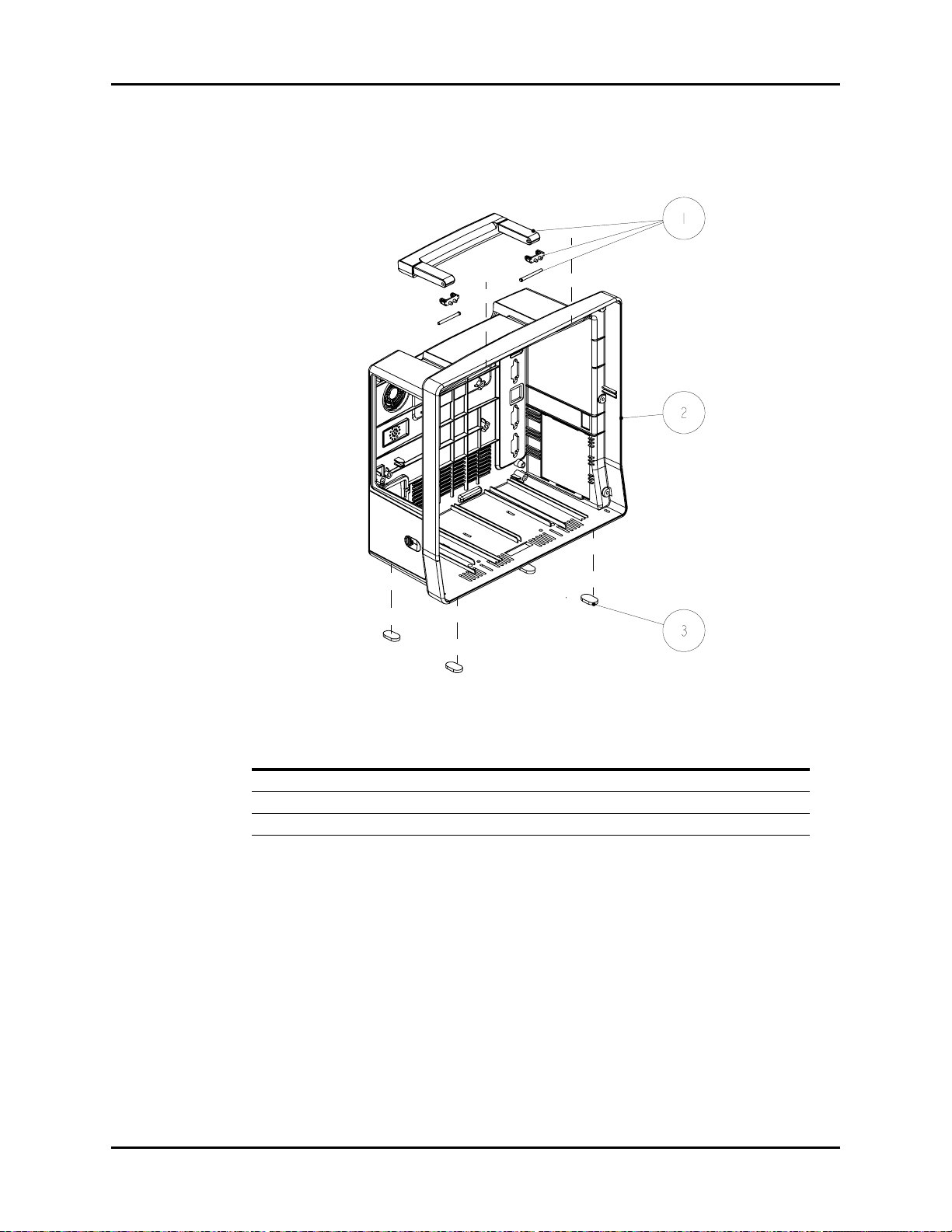
Isometric Drawings and Parts List Rear Housing Sub-assembly
4.5 Rear Housing Sub-assembly
FIGURE 4-4 Rear Housing Sub-assembly
ITEM NO DESCRIPTION PART NUMBER
1 Handle service kit 801-6100-00009-00
2 Rear Housing service kit 801-6100-00010-00
3 Foot DA6H-20-22831
Passport V™ Service Manual 0070-10-0705 4 - 7

Isometric Drawings and Parts List Main Chassis Sub-assembly
4.6 Main Chassis Sub-assembly
Passport V™ Service Manual 0070-10-0705 4 - 8
FIGURE 4-5 Main Chassis Sub-assembly

Isometric Drawings and Parts List Main Chassis Sub-assembly
ITEM NO DESCRIPTION PART NUMBER
1 Interface Connector PCB Assembly 801-6100-00025-00
2 Cable from the interface board to CF card board 6100-20-86302
3 CF card assembly 801-6100-00012-00
4 Storage card CF card 1GB iCF4000 801-0000-00006-00
5 Speaker bolster plate 6100-20-86281
6 Fan service kit 801-6100-00013-00
7 Plate, Fan Retaining 6101-20-46731
8 Screw, Flat Head Phillips M3X25 M04-051172---
9 Module, Wireless AP 801-6100-00014-00
10 Retainer plate, speaker 6100-20-86280
11 Speaker gasket 6006-20-39418
12 Screw, Combined screw M3X8 N/A
13 Speaker cable 4ohm 2W 350mm 020-000001-00
14 Gasket, Speaker pressure plate and spacer 8002-20-36218
15 AC Inlet with Cable Assembly 9211-20-87221
16 Grounding terminal 0509-20-00098
17 Serrated lock washers external teeth GB/T862.2-1987 6
M04-021048---
plated with anti-rustiness nickel
18 Washer, Grounding pillar 6100-20-86393
19 Bracket, AC Inlet N/A
20 PCBA, Power Supply 801-6100-00015-00
21 Insulator, Power Supply Board N/A
22 Screw, Flat Head Phillips M3X6 N/A
23 Battery latch 6100-20-86255
24 Battery latch spring 6100-20-86252
25 Battery compartment overlay 6100-20-86406
26 Clapboard, battery (tool HM-070) 9000-20-07329
27 Screw, Flat Head Self-Tapping PT3X8 N/A
28 Bracket, Main N/A
29 Battery latch retaining plate N/A
30 Spring, EMI 0000-10-10996
31 PCBA, Li-Battery 801-6100-00016-00
32 Nut, Lock WasherM3 N/A
33 Cable Assembly, Local Printer 9211-20-87228
34 Plate, Local Printer Mounting N/A
35 Screw, Pan Head W/Washer Phillips M3X6 M04-004012---
Passport V™ Service Manual 0070-10-0705 4 - 9

Interface Connector PCB Assembly Isometric Drawings and Parts List
4.7 Interface Connector PCB Assembly
FIGURE 4-6 Interface Connector PCB Assembly
ITEM NO DESCRIPTION PART NUMBER
1 Spring, EMI M6T-030006---
2 Bracket, Interface Board Mounting 6100-20-86277
3 Seal (O-ring) 9.5X1.8 silicone A75 (brown) M6M-010009---
4 Silica gel waterproof wrap, SB 6100-20-86275
5 PCBA, Power Supply Management and Interface Use assembly P/N
6 Bracket, Interface Board Top N/A
7 Bracket, Interface Board Bottom N/A
8 Gasket, Network Socket 9211-20-87440
9 Screw, Pan Head W/Washer Phillips M3X6 M04-004012---
10 Spring, EMI 0000-10-10996
801-6100-00025-00
4 - 10 0070-10-0705 Passport V™ Service Manual

Isometric Drawings and Parts List Parameter Sub-assembly
4.8 Parameter Sub-assembly
FIGURE 4-7 Parameter Sub-assembly
ITEM NO DESCRIPTION PART NUMBER
1 Screw, Pan Head W/Washer Phillips M3X6 M04-004012---
2 Module, Integrated Parameter 801-6100-00017-00
3 Frame, Parameter Board Mounting 6100-20-86276
4 Cable Assembly, NIBP 6100-20-86305
5 NIBP Module Assembly 801-6100-00026-00
6 Masimo SpO
6 Nellcor SpO
6 DPM SpO
7 Sub-assembly, Patient Connector 801-6100-00018-00
Module Assembly 801-6100-00028-00
2
Module Assembly 801-6100-00027-00
2
Module Assembly 801-6100-00024-00
2
Passport V™ Service Manual 0070-10-0705 4 - 11

Patient Connector Sub-assembly Isometric Drawings and Parts List
4.9 Patient Connector Sub-assembly
FIGURE 4-8 Patient Connector Sub-assembly
ITEM NO DESCRIPTION PART NUMBER
1 Blank Cover Plate, CO
1 Watertrap assembly, Sidestream CO
1 Assembly, Micro-stream CO
2 Gas Outlet 6200-20-11614
3 Assembly, NIBP Connector DA6H-20-22833
4 Parameter Connector Panel 6100-30-86328
5 Nut, Stainless Steel M5 GB6170 N/A
Opening 6100-20-86297
2
2
Receptacle 801-6100-00020-00
2
See DPM CO2 Module
Assembly
4 - 12 0070-10-0705 Passport V™ Service Manual

Isometric Drawings and Parts List NIBP Module Assembly
4.10 NIBP Module Assembly
FIGURE 4-9 NIBP Module Assembly
ITEM NO DESCRIPTION PART NUMBER
1 Plate, NIBP Mounting N/A
2 PCBA, NIBP PCBA module 801-6100-00019-00
3 Connector. Elbow Reduction, 1/8" & 3/32" ID, White N/A
4 Connector Tee, 200Barb, 3/32" ID, White Nylon N/A
5 Tubing. Silicone, 1/16" X 3/16", TYGON 3350 (1feet) M6G-020006---
6 Air filter hose ID. 1/8", 25um S1-0378-02-0004
7 Valve, Quick Deflate 801-6101-00012-00
8 Screw, Pan Head Phillips M3X18 N/A
9 Proportional solenoid valve: normally open 801-6101-00013-00
10 Frame, NIBP Tubing Retaining N/A
11 Tubing, Silicone, Five Branch N/A
12 Screw, Pan Head Phillips M3X6 N/A
13 TUBE. Silicone, 1/8" X 1/4" X100ft,2800546-100 A21-000002---
14 Pump 801-6101-00018-00
15 Cable Assembly, NIBP 6100-20-86305
16 Screw, Self-Tapping PT2.6X6 N/A
17 Screw, Flat Head Phillips M2X4 N/A
Passport V™ Service Manual 0070-10-0705 4 - 13

Microstream CO2 Module Assembly Isometric Drawings and Parts List
4.11 Microstream CO2 Module Assembly
FIGURE 4-10 Microstream CO2 Module Assembly
ITEM NO DESCRIPTION PART NUMBER
1 Screw, Pan Head W/Washer Phillips M3X6 N/A
2 Bracket, Micro-Stream CO
3 Cable Assembly, Micro-Stream CO
4 PCBA, Micro-Stream CO
5 Cable Assembly, Micro-Stream CO
6 Screw, Pan Head Phillips M3X6 N/A
7 Module, Micro-Stream CO
8 Assembly, Micro-stream CO
Mounting N/A
2
to Transfer Board 9201-20-35932
2
Transfer N/A
2
2
2
Receptacle 801-6100-00020-00
2
9211-20-87247
N/A
4 - 14 0070-10-0705 Passport V™ Service Manual

Isometric Drawings and Parts List DPM CO2 Module Assembly
4.12 DPM CO2 Module Assembly
FIGURE 4-11 DPM CO2 Module
ITEM NO DESCRIPTION PART NUMBER
1 Bracket, Sidestream CO
2 Cable Assembly, Sidestream CO
3 Screw, Pan Head Cross Recessed M3X6 N/A
4 Moisture exchanger (Nafion Tube for DPM CO
5 Cushion, water trap receptacle 6100-20-86355
6 Mounting Frame. DRYLINE, Flush 040-000226-00
7 Screw, Pan head Self-Tapping PT2X6 N/A
8 Tubing (ID 1/16’ OD 1/8’) (20feet) 3001-10-07069
9 Flush Mount, Water Trap 040-000225-00
10 Flow restrictor tube M02A-21-25944
11 Cable Assembly, Watertrap cable 009-000101-00
12 Module, CO
13 Screw, Pan Head W/Washer Phillips M3X6 M04-004012---
Host (M02B) N/A
2
Mounting N/A
2
2
) M02A-10-25936
2
6100-20-86321
Passport V™ Service Manual 0070-10-0705 4 - 15

Masimo SpO2 PCB Assembly Isometric Drawings and Parts List
4.13 Masimo SpO2 PCB Assembly
FIGURE 4-12 Masimo SpO2 PCB Assembly
ITEM NO DESCRIPTION PART NUMBER
1 Large Flat Washer, GB96 3 N/A
2 Spring Washer, GB93 3 N/A
3 Screw, Stud M3X7 N/A
4 PCBA, Masimo Transfer Board 801-6101-00015-00
5 Communication cable. OEM SpO
6 Screw, Pan Head W/Washer Phillips M3X6 M04-004012---
7 Nut, Stainless Steel M3 GB6170 N/A
8 Washer, insulating 3X1mm N/A
9 SpO
10 Screw, Flat Head PhillipsM2.5X4 N/A
11 Frame, Masimo SpO
12 Screw, Self-Tapping PT3X8 N/A
13 Screw, Pan Head Phillips M3X6 N/A
14 Masimo MS-2013 board 801-6101-00016-00
flex cable assembly 2685 040-000150-00
2
Connector 6101-20-46720-52
2
2
9211-20-87242
4 - 16 0070-10-0705 Passport V™ Service Manual

Isometric Drawings and Parts List Nellcor SpO2 Module Assembly
4.14 Nellcor SpO2 Module Assembly
FIGURE 4-13 Nellcor SpO2 Module Assembly
ITEM NO DESCRIPTION PART NUMBER
1 Nellcor SpO
2 Nellcor cable assembly 801-6100-00022-00
3 Screw, Flat Head Phillips M2.5X4 N/A
4 Frame, Nellcor SpO
5 Screw, Self-Tapping PT3X8 N/A
6 Nut, Stud M3X12 N/A
7 Screw, Phillips Pan Head Washer M3X18 N/A
8 Isolated power and signal conversion board PCBA,
Nellcor SpO
9 Communication cable. OEM SpO
10 Screw, Pan Head W/Washer Phillips M3X6 M04-004012---
board service kit 801-6100-00023-00
2
Interface 6101-20-46719-52
2
module
2
2
801-6101-00017-00
9211-20-87242
Passport V™ Service Manual 0070-10-0705 4 - 17

Nellcor SpO2 Module Assembly Isometric Drawings and Parts List
This page intentionally left blank.
4 - 18 0070-10-0705 Passport V™ Service Manual

5.0
Calibration Procedure
5.1 Introduction
The following procedures are provided to verify the proper operation of the Passport V
Monitor. Service Diagnostics provides the capability of diagnosing problems within the
Passport V hardware. A menu driven interface, similar to that of the Passport V user
interface, is used to execute all tests.
CAUTION: Calibration is not to be performed while monitoring a
patient.
5.2 Warnings and Guidelines
If the instrument covers are removed, observe the following warnings and general guidelines:
1. Do not short component leads together.
2. Perform all steps in the exact order given.
3. Use extreme care when reaching inside the opened instrument. Do not contact exposed
metal parts which may become electrically active.
4. Read and understand each step of the procedure prior to beginning the step.
Passport V™ Service Manual 0070-10-0705 5 - 1
 Loading...