


Operating Instructions
™
™
|
Anesthesia System

Operating Instructions
™
™
|
Anesthesia System

A5™ and A3™ are U.S. trademarks of Mindray DS USA, Inc.
Selectatec® is a registered trademark of Ohmeda.
Copyright © Mindray DS USA, Inc., 2010. All rights reserved. Contents of this publication may not be reproduced in any
form without permission of Mindray DS USA, Inc.


Table of Contents
Foreword .................................................................................................................................................................................................................................vii
Indications For Use ..............................................................................................................................................................................................................vii
Responsibilities of Operators...........................................................................................................................................................................................vii
Warnings, Cautions, and Notes.......................................................................................................................................................................................vii
Warnings..................................................................................................................................................................................................................................viii
Cautions...................................................................................................................................................................................................................................xii
Notes.........................................................................................................................................................................................................................................xv
Warranty Statements ..........................................................................................................................................................................................................xvii
Disclaimers..............................................................................................................................................................................................................................xvii
Phone Numbers and How To Get Assistance.............................................................................................................................................................xviii
Manufacturer’s Responsibility .........................................................................................................................................................................................xviii
Symbols....................................................................................................................................................................................................................................xviii
Product Description....................................................................................................................................................1 - 1
General System Overview ...................................................................................................................................................................................................1 - 2
General Description....................................................................................................................................................................................................1 - 2
Key Features ..................................................................................................................................................................................................................1 - 3
Fresh Gas Dosing .........................................................................................................................................................................................................1 - 3
Flow Control..................................................................................................................................................................................................................1 - 4
Flow/Pressure Sensing ...................................................................................................................................................................................1 - 4
Vaporizer Mounting....................................................................................................................................................................................................1 - 4
Anesthesia Ventilator.................................................................................................................................................................................................1 - 4
Breathing System ........................................................................................................................................................................................................1 - 4
Anesthetic Gas Scavenging System (AGSS).......................................................................................................................................................1 - 5
Power Management / Battery Supply..................................................................................................................................................................1 - 5
Workplace Ergonomics..............................................................................................................................................................................................1 - 7
Hook .................................................................................................................................................................................................................................1 - 7
Physical Views..........................................................................................................................................................................................................................1 - 8
Main Unit (Front View)...............................................................................................................................................................................................1 - 8
Main Unit (Rear View).................................................................................................................................................................................................1 - 10
Main Unit (Left View)..................................................................................................................................................................................................1 - 12
Main Unit (Right View)...............................................................................................................................................................................................1 - 13
Main Unit (Top View)..................................................................................................................................................................................................1 - 14
Breathing System (Top View)..................................................................................................................................................................................1 - 15
Breathing System (Left View)..................................................................................................................................................................................1 - 17
Anesthetic Gas Scavenging System (AGSS) (Top, Right, and Rear Views) ..............................................................................................1 - 18
Installation ..................................................................................................................................................................2 - 1
Unpacking.................................................................................................................................................................................................................................2 - 3
Initial Setup...............................................................................................................................................................................................................................2 - 4
Install the Vaporizer...............................................................................................................................................................................................................2 - 5
Filling and Draining the Vaporizer ........................................................................................................................................................................2 - 7
System Interface .........................................................................................................................................................3 - 1
Main Screen Components...................................................................................................................................................................................................3 - 2
System Information Header ...............................................................................................................................................................................................3 - 6
Elapsed Timer................................................................................................................................................................................................................3 - 6
Patient Size ....................................................................................................................................................................................................................3 - 6
Alarm and Prompt Messages ..................................................................................................................................................................................3 - 6
Alarm Silence Icon.......................................................................................................................................................................................................3 - 7
Date and Time ..............................................................................................................................................................................................................3 - 8
Battery Status................................................................................................................................................................................................................3 - 9
Fresh Gas Flow Display.........................................................................................................................................................................................................3 - 10
Waveforms Tab .......................................................................................................................................................................................................................3 - 11
Waveform Color ...........................................................................................................................................................................................................3 - 11
A5/A3™ Operating Instructions 046-003777-00 i

Table of Contents
Waveforms Autoscaling............................................................................................................................................................................................3 - 12
Spirometry Tab (A5 Only)....................................................................................................................................................................................................3 - 13
Loop Type.......................................................................................................................................................................................................................3 - 14
Show Reference ...........................................................................................................................................................................................................3 - 14
Save Loop.......................................................................................................................................................................................................................3 - 14
Review Loops Button .................................................................................................................................................................................................3 - 15
Demographics Tab.................................................................................................................................................................................................................3 - 17
Ventilation Mode Tabs..........................................................................................................................................................................................................3 - 19
Measured Values Area ..........................................................................................................................................................................................................3 - 21
System Softkeys......................................................................................................................................................................................................................3 - 22
Setup Softkey................................................................................................................................................................................................................3 - 22
Alarms Softkey..............................................................................................................................................................................................................3 - 22
Silence Softkey .............................................................................................................................................................................................................3 - 22
Capture Event (Software Version 03.02.00 and later).....................................................................................................................................3 - 22
History (Software Version 03.02.00 and later)...................................................................................................................................................3 - 22
List Trends ..........................................................................................................................................................................................................3 - 22
Graphic Trends (Software Version 03.04.00 and later) .......................................................................................................................3 - 24
Event Log ............................................................................................................................................................................................................3 - 27
Setup...........................................................................................................................................................................................................................................3 - 29
General Tab ..............................................................................................................................................................................................................................3 - 29
Display Tab ...............................................................................................................................................................................................................................3 - 31
System Tab................................................................................................................................................................................................................................3 - 34
Network Configuration..............................................................................................................................................................................................3 - 37
Service Tab................................................................................................................................................................................................................................3 - 40
Preoperative Tests......................................................................................................................................................4 - 1
Preoperative Test Schedules..............................................................................................................................................................................................4 - 2
Test Intervals .................................................................................................................................................................................................................4 - 2
Inspect the System.................................................................................................................................................................................................................4 - 3
Pre-Operative Checkout List...............................................................................................................................................................................................4 - 4
Introduction...................................................................................................................................................................................................................4 - 4
Suggested Pre-Operative Checkout List.............................................................................................................................................................4 - 4
System Self-Test......................................................................................................................................................................................................................4 - 6
Leak and Compliance Tests ................................................................................................................................................................................................4 - 9
Automatic Circuit Leak and Compliance Test...................................................................................................................................................4 - 9
Manual Circuit Leak Test...........................................................................................................................................................................................4 - 14
Power Failure Alarm Test.....................................................................................................................................................................................................4 - 17
Pipeline Tests ...........................................................................................................................................................................................................................4 - 17
Pipeline Test............................................................................................................................................................................................................4 - 17
O
2
O Pipeline Test.........................................................................................................................................................................................................4 - 17
N
2
Air Pipeline Test............................................................................................................................................................................................................4 - 18
Basic Ventilation Testing......................................................................................................................................................................................................4 - 18
Cylinder Tests...........................................................................................................................................................................................................................4 - 19
Check the Cylinder Pressure....................................................................................................................................................................................4 - 19
Cylinder High Pressure Leak Test ....................................................................................................................................................................4 - 19
O
2
O Cylinder High Pressure Leak Test.................................................................................................................................................................4 - 19
N
2
Air Cylinder High Pressure Leak Test....................................................................................................................................................................4 - 19
Flow Control System Test....................................................................................................................................................................................................4 - 20
Vaporizer Tests ........................................................................................................................................................................................................................4 - 21
Vaporizer Back Pressure Test...................................................................................................................................................................................4 - 21
Manual Leak Test.........................................................................................................................................................................................................4 - 21
Vaporizer Leak Test.....................................................................................................................................................................................................4 - 21
Breathing System Tests........................................................................................................................................................................................................4 - 23
ii 046-003777-00 A5/A3™ Operating Instructions

Table of Contents
Bellows Test...................................................................................................................................................................................................................4 - 23
Breathing System Leak Test in Manual Ventilation Status ...........................................................................................................................4 - 23
APL Valve Test...............................................................................................................................................................................................................4 - 24
Alarm Tests ...............................................................................................................................................................................................................................4 - 25
Prepare for Alarm Tests.............................................................................................................................................................................................4 - 25
Test the O
Concentration Monitoring and Alarms........................................................................................................................................4 - 25
2
Test the Low Minute Volume (MV) Alarm...........................................................................................................................................................4 - 26
Test the Apnea Alarm.................................................................................................................................................................................................4 - 26
Test the Continuous Airway Pressure Alarm .....................................................................................................................................................4 - 26
Test the High Paw Alarm...........................................................................................................................................................................................4 - 27
Test the Low Paw Alarm............................................................................................................................................................................................4 - 27
Preoperative Preparations ..................................................................................................................................................................................................4 - 27
Inspect the AGSS ....................................................................................................................................................................................................................4 - 28
Operations...................................................................................................................................................................5 - 1
Powering On the A5/A3 Anesthesia System ................................................................................................................................................................5 - 2
Powering Off the A5/A3 Anesthesia System................................................................................................................................................................5 - 2
Patient Setup............................................................................................................................................................................................................................5 - 3
Discharge / Standby Mode.......................................................................................................................................................................................5 - 3
Select the Patient Size (Adult, Pediatric, Infant)...............................................................................................................................................5 - 5
Oxygen Sensor Calibration.................................................................................................................................................................................................5 - 5
Input Fresh Gas .......................................................................................................................................................................................................................5 - 6
O, Air, and O2 Inputs ......................................................................................................................................................................................5 - 6
Set N
2
Set Anesthetic Agent .................................................................................................................................................................................................5 - 6
Select the Desired Anesthetic Agent ........................................................................................................................................................5 - 7
Adjust the Concentration of Anesthetic Agent ....................................................................................................................................5 - 7
Ventilation Modes..................................................................................................................................................................................................................5 - 8
Monitored Parameters...............................................................................................................................................................................................5 - 8
Ventilation Modes .......................................................................................................................................................................................................5 - 8
Change Ventilation Mode ........................................................................................................................................................................................5 - 8
Set Manual Ventilation Mode..................................................................................................................................................................................5 - 9
Setting Monitor Mode (A5 with AG Module connected)..............................................................................................................................5 - 11
Make Settings before Starting Mechanical Ventilation Mode ....................................................................................................................5 - 13
Set Volume Control Ventilation (VCV)..................................................................................................................................................................5 - 14
To Set VCV Mode ..............................................................................................................................................................................................5 - 14
Set Pressure Control Ventilation (PCV) ................................................................................................................................................................5 - 15
To Set PCV Mode ..............................................................................................................................................................................................5 - 15
Synchronized Intermittent Mandatory Ventilation (SIMV)...........................................................................................................................5 - 16
Pressure Support in Synchronized Intermittent Mandatory Ventilation (SIMV) .......................................................................5 - 16
Synchronized Intermittent Mandatory Ventilation–Volume Control (SIMV-VC) ......................................................................5 - 16
Synchronized Intermittent Mandatory Ventilation–Pressure Control (SIMV-PC) - A5 Only .................................................5 - 17
To Set SIMV-VC or SIMV-PC Mode .............................................................................................................................................................5 - 17
Set Pressure Support Ventilation (PS)..................................................................................................................................................................5 - 18
To Set PS Mode .................................................................................................................................................................................................5 - 18
Start Mechanical Ventilation..............................................................................................................................................................................................5 - 19
Stop Mechanical Ventilation ..............................................................................................................................................................................................5 - 19
Relationships of Ventilation Parameters........................................................................................................................................................................5 - 19
Parameter Monitoring (Waveforms)................................................................................................................................................................................5 - 20
Pressure...........................................................................................................................................................................................................................5 - 20
Auto-zeroing the Pressure Sensors ...........................................................................................................................................................5 - 21
Volume ............................................................................................................................................................................................................................5 - 21
Gas (available with the AG module) .....................................................................................................................................................................5 - 22
Inspired O
(available without the AG module)...............................................................................................................................................5 - 22
2
A5/A3™ Operating Instructions 046-003777-00 iii

Table of Contents
Spirometry (A5 Only)..................................................................................................................................................................................................5 - 22
Spirometry Loops ............................................................................................................................................................................................5 - 23
Waveform Autoscaling ..................................................................................................................................................................................5 - 24
Alarms and Messages .................................................................................................................................................6 - 1
Introduction .............................................................................................................................................................................................................................6 - 2
Alarm System Self-Test..............................................................................................................................................................................................6 - 2
Types of Alarms and Messages...............................................................................................................................................................................6 - 3
Alarm Indicators...........................................................................................................................................................................................................6 - 4
Displaying Alarms ..................................................................................................................................................................................................................6 - 5
Displayed Order of Alarm Messages.....................................................................................................................................................................6 - 6
Setting Alarm Volume ..........................................................................................................................................................................................................6 - 7
Silencing Alarms .....................................................................................................................................................................................................................6 - 8
Alarm Limits..............................................................................................................................................................................................................................6 - 9
Setting Alarm Limits...................................................................................................................................................................................................6 - 9
Loading Alarm Defaults.............................................................................................................................................................................................6 - 11
Auto Alarm Limits........................................................................................................................................................................................................6 - 13
Alarm and Prompt Messages.............................................................................................................................................................................................6 - 14
Technical Alarm Messages.......................................................................................................................................................................................6 - 17
Startup Alarm Messages ...............................................................................................................................................................................6 - 17
CPU Board Runtime Alarm ...........................................................................................................................................................................6 - 19
Power Board Runtime Alarm .......................................................................................................................................................................6 - 20
Electronic Flowmeter Board Runtime Alarm .........................................................................................................................................6 - 20
Ventilator Control Board Runtime Alarm ................................................................................................................................................6 - 21
AG Module Alarm Messages ........................................................................................................................................................................6 - 23
Prompt Messages........................................................................................................................................................................................................6 - 26
Prompt Messages Displayed in Alarm Area ...........................................................................................................................................6 - 26
Prompt Messages Displayed in Pop-up Area ........................................................................................................................................6 - 27
Maintenance ...............................................................................................................................................................7 - 1
Theory of Operation..............................................................................................................................................................................................................7 - 3
Block Diagram..........................................................................................................................................................................................................................7 - 3
Maintenance Schedule.........................................................................................................................................................................................................7 - 4
Breathing System Maintenance........................................................................................................................................................................................7 - 4
Flow Sensor Calibration.......................................................................................................................................................................................................7 - 5
Sensor Calibration............................................................................................................................................................................................................7 - 6
O
2
Calibrate the O2 Sensor.............................................................................................................................................................................................7 - 7
Water Build-up in the Flow Sensor...................................................................................................................................................................................7 - 9
Prevent Water Build-up.............................................................................................................................................................................................7 - 9
Clear Water Build-up ..................................................................................................................................................................................................7 - 9
AGSS Transfer Tube Maintenance....................................................................................................................................................................................7 - 9
Electrical Safety Inspection.................................................................................................................................................................................................7 - 9
Auxiliary Electrical Outlet Test................................................................................................................................................................................7 - 9
Electrical Safety Inspection Test.............................................................................................................................................................................7 - 10
Cleaning and Disinfection...................................................................................................................................................................................................7 - 11
General Guidelines......................................................................................................................................................................................................7 - 11
Cleaning and Disinfecting Agents / Autoclaving.............................................................................................................................................7 - 11
External Surfaces..........................................................................................................................................................................................................7 - 11
Bellows Assembly........................................................................................................................................................................................................7 - 12
Inspiration and Expiration Valves..........................................................................................................................................................................7 - 15
Oxygen Sensor..............................................................................................................................................................................................................7 - 17
APL Valve........................................................................................................................................................................................................................7 - 18
PAW Gauge....................................................................................................................................................................................................................7 - 19
Bag Arm...........................................................................................................................................................................................................................7 - 20
iv 046-003777-00 A5/A3™ Operating Instructions

Table of Contents
Absorber Canister........................................................................................................................................................................................................7 - 21
Breathing System Block.............................................................................................................................................................................................7 - 23
AGSS (Anesthetic Gas Scavenging System) and AGSS Transfer Hose......................................................................................................7 - 25
Regular Maintenance............................................................................................................................................................................................................7 - 27
AG and O2 Concentration Monitoring ......................................................................................................................8 - 1
Introduction .............................................................................................................................................................................................................................8 - 2
Understand MAC Values......................................................................................................................................................................................................8 - 3
Identify External AG Modules ............................................................................................................................................................................................8 - 4
Prepare to Measure AG ........................................................................................................................................................................................................8 - 5
Make AG Settings ...................................................................................................................................................................................................................8 - 6
Set CO2 Unit ..................................................................................................................................................................................................................8 - 6
Set CO2 Placement .....................................................................................................................................................................................................8 - 6
Set CO2 Scale ................................................................................................................................................................................................................8 - 6
Gas Bench Flow Rate ..................................................................................................................................................................................................8 - 6
Set Alarm Limits ...........................................................................................................................................................................................................8 - 7
Measurement Limitations ...................................................................................................................................................................................................8 - 8
Troubleshooting.....................................................................................................................................................................................................................8 - 8
Scavenge the Sample Gas...................................................................................................................................................................................................8 - 9
Calibrate the AG Module .....................................................................................................................................................................................................8 - 10
Product Specifications................................................................................................................................................9 - 1
Standards Compliance .........................................................................................................................................................................................................9 - 2
Safety Designations...............................................................................................................................................................................................................9 - 3
Oxygen Enriched Environments............................................................................................................................................................................9 - 3
Wiring and PC Board Materials...............................................................................................................................................................................9 - 3
Physical Specifications..........................................................................................................................................................................................................9 - 4
Stability Configurations and Conditions........................................................................................................................................................................9 - 4
Environmental Specifications............................................................................................................................................................................................9 - 5
Electrical Specifications........................................................................................................................................................................................................9 - 6
Main Electrical Power Specifications....................................................................................................................................................................9 - 6
Battery Power Specifications...................................................................................................................................................................................9 - 6
Auxiliary Electrical Outlets........................................................................................................................................................................................9 - 6
Communication Ports................................................................................................................................................................................................9 - 7
Pneumatic Specifications ....................................................................................................................................................................................................9 - 8
Pipeline Supply (N
Cylinder Supply (N
Vaporizer Connections ..............................................................................................................................................................................................9 - 8
Drive Gas.........................................................................................................................................................................................................................9 - 8
O Automatic Cutoff................................................................................................................................................................................................9 - 8
N
2
Controls ....................................................................................................................................................................................................................9 - 8
O
2
Oxygen Ratio Controller............................................................................................................................................................................................9 - 8
Breathing System Specifications ......................................................................................................................................................................................9 - 9
Breathing System Volume........................................................................................................................................................................................9 - 9
Absorber Assembly............................................................................................................................................................................................9 - 9
CO
2
Water Trap......................................................................................................................................................................................................................9 - 9
Breathing System Connections..............................................................................................................................................................................9 - 9
APL Valve........................................................................................................................................................................................................................9 - 9
Breathing System Temperature Controller........................................................................................................................................................9 - 10
Breathing Circuit Parameters..................................................................................................................................................................................9 - 10
Materials .........................................................................................................................................................................................................................9 - 11
Anesthetic Gas Scavenging System (AGSS)..................................................................................................................................................................9 - 11
Monitor Module......................................................................................................................................................................................................................9 - 11
AG Module .....................................................................................................................................................................................................................9 - 11
O, Air, O2) .................................................................................................................................................................................9 - 8
2
O, Air, O2).................................................................................................................................................................................9 - 8
2
A5/A3™ Operating Instructions 046-003777-00 v

Table of Contents
Alarms..............................................................................................................................................................................................................................9 - 13
Effect of Interfering Gas on AG Measured Value..............................................................................................................................................9 - 13
Ventilator Specifications......................................................................................................................................................................................................9 - 15
Displays and Controls Specifications ..............................................................................................................................................................................9 - 18
Electronic Controls......................................................................................................................................................................................................9 - 18
Pneumatic Controls ....................................................................................................................................................................................................9 - 18
Alarms.........................................................................................................................................................................................................................................9 - 20
Safety Specifications .............................................................................................................................................................................................................9 - 21
ASTM F 1208 – 89 (2005) Disclosures..............................................................................................................................................................................9 - 23
Leakage of Breathing System..................................................................................................................................................................................9 - 23
Resistance of Breathing Systems ...........................................................................................................................................................................9 - 23
Absorber Resistance..........................................................................................................................................................................................9 - 23
CO
2
Absorber Capacity..............................................................................................................................................................................................9 - 23
CO
2
Unidirectional Valve Opening Pressure...............................................................................................................................................................9 - 23
Data Storage (Non-Volatile) and Recording .................................................................................................................................................................9 - 24
Electromagnetic Capability ................................................................................................................................................................................................9 - 25
Accessories ................................................................................................................................................................. A - 1
Accessory Kits ......................................................................................................................................................................................................................... A - 2
AG Accessories ....................................................................................................................................................................................................................... A - 2
Absorbent Canister...................................................................................................................................................................................................... A - 2
CO
2
Gas Cylinder Accessories ....................................................................................................................................................................................................A - 3
Gas Supply Hoses .................................................................................................................................................................................................................. A - 3
Manuals and Reference Cards .......................................................................................................................................................................................... A - 3
Mounting Accessories .........................................................................................................................................................................................................A - 4
Networking and USB Storage ...........................................................................................................................................................................................A - 4
Vaporizers................................................................................................................................................................................................................................. A - 5
User Accessible Spare Parts .......................................................................................................................................B - 1
AGSS............................................................................................................................................................................................................................................B - 2
Breathing System ...................................................................................................................................................................................................................B - 2
Absorbent Canister.......................................................................................................................................................................................................B - 2
CO
2
Flow Sensor ..............................................................................................................................................................................................................................B - 2
Gas Cylinder Accessories .....................................................................................................................................................................................................B - 3
Sensor...................................................................................................................................................................................................................................B - 3
O
2
Parameters and Factory Defaults..............................................................................................................................C - 1
Waveform/Spirometry Tabs (A5 Only)........................................................................................................................................................................... C - 2
Alarm Limits............................................................................................................................................................................................................................. C - 3
Setup Menu ............................................................................................................................................................................................................................. C - 6
Alarm Volume and History................................................................................................................................................................................................. C - 8
Date and Time ........................................................................................................................................................................................................................ C - 8
Demographics........................................................................................................................................................................................................................ C - 9
Ventilation Modes................................................................................................................................................................................................................. C - 9
Linked Ventilation Parameter Relationships ............................................................................................................................................................... C - 13
Non-Linked Ventilation Parameter Relationships ..................................................................................................................................................... C - 15
Pneumatic Diagram................................................................................................................................................... D - 1
Pneumatic Diagram of the A5/A3 System....................................................................................................................................................................D - 2
Abbreviations, Symbols, and Units of Measure .......................................................................................................E - 1
Abbreviations ..........................................................................................................................................................................................................................E - 2
Symbols......................................................................................................................................................................................................................................E - 4
Units of Measure.....................................................................................................................................................................................................................E - 5
Attention Symbols.................................................................................................................................................................................................................E - 6
vi 046-003777-00 A5/A3™ Operating Instructions

Foreword Introduction
Foreword
WARNING: Do not operate the A5/A3 Anesthesia System before reading these
instructions.
The operating instructions for the A5/A3 Anesthesia Delivery System (hereinafter referred to as A5/A3
Anesthesia System, A5/A3 System, A5/A3, or individual A5 and A3) are intended to provide
information for proper installation, operation, and general maintenance of the A5/A3 System to the
user.
General knowledge and understanding of the features and functions of the A5/A3 System are
prerequisites for its proper use.
For servicing information or assistance, please contact an authorized representative in your area.
CAUTION: U.S. Federal Law restricts this device to sale by or on the order of a
NOTE: Figures in this manual are provided for reference purposes only.
physician or other practitioner licensed by state law to use or order the
use of this device.
Screens may differ based on the system configuration and selected
parameters.
Indications For Use
The A5/A3 Anesthesia System is a device used to administer to a patient, continuously or
intermittently, a general inhalation anesthetic, and to maintain a patient's ventilation.
The A5/A3 is intended for use by licensed clinicians, for patients requiring anesthesia within a health
care facility, and can be used for adult and pediatric populations.
WARNING: The A5/A3 is intended to be operated only by licensed clinicians and
qualified anesthesia personnel who have received adequate training in
its use. Anyone unauthorized or untrained must not perform any
operation on the A5/A3.
WARNING: The A5/A3 is not suitable for use in an MRI environment.
Responsibilities of Operators
The proper function of the A5/A3 System can only be guaranteed if it is operated and serviced in
accordance with the information provided in this manual and by an authorized Mindray service
representative. Non-compliance with this information voids all guarantee claims.
The A5/A3 System must be operated by qualified and trained personnel only. All operators must fully
observe these operating instructions and relevant additional documentation. They must also comply
with the WAR NIN GS , CAUTIONS, and NOTES detailed in this manual.
Warnings, Cautions, and Notes
Please adhere to all warnings, cautions, and notes that are listed throughout this manual. They are
summarized here for your reference.
WAR NIN G — Indicates a potential hazard or unsafe practice that, if not avoided, could result in death
or serious injury to the patient or user.
CAUTION — Indicates a potential hazard or unsafe practice that, if not avoided, could result in
product/property damage or minor personal injury to the patient or user.
NOTE — Provides application tips or other useful information.
A5/A3™ Operating Instructions 046-003777-00 vii

Introduction Warning s
Warnings
WARNING: Do not operate the A5/A3 Anesthesia System before reading these
WARNING: All analog or digital products connected to this system must be
WARNING: This machine must only be operated by trained, skilled medical staff.
WARNING: Before putting the system into operation, the operator must verify that
WARNING: The equipment must be connected to a properly installed power outlet
WARNING: Multiple AC power outlets are provided on the rear of the A5/A3. These
instructions.
certified passing the specified IEC standards (such as IEC 60950 for data
processing equipment and IEC 60601-1 for medical electrical
equipment). All configurations shall comply with the valid version of
IEC 60601-1-1. The personnel who are responsible for connecting the
optional equipment to the I/O signal port shall be responsible for
medical system configuration and system compliance with IEC
60601-1-1.
the equipment, connecting cables, and accessories are in correct
working order and operating condition.
with protective earth contacts only. If the installation does not provide
for a protective earth conductor, disconnect it from the power line or
operate from the equipment’s internal battery supply.
outlets are intended to supply power to additional equipment that
form a part of the anesthesia system (i.e. vaporizers, gas analyzers,
etc.). Do not connect other equipment to these outlets, as patient
leakage current may be affected. Each outlet is rated 3 A; the total
current that may be drawn through all outlets is 10 A on the A5 System
and 9 A on the A3 System; do not attempt to exceed these load ratings.
Do not connect additional Multiple Portable Socket Outlets (i.e.
Multiple outlet extension cords) (MPSOs) or extension cords to these
outlets.
WARNING: Do not put MPSOs (on the floor.
WARNING: Connect the A5/A3 Anesthesia System to an AC power source before the
internal battery power source is depleted.
WARNING: Do not open the equipment housings. All servicing and future
upgrades must be carried out only by trained and authorized Mindray
personnel.
WARNING: Do not rely exclusively on the audible alarm system for patient
WARNING: Adjustment of alarm volume to a low level may result in a hazard to the
WARNING: Alarm settings should be customized according to different patient
WARNING: The physiological parameters and alarm messages displayed on the
WARNING: Dispose of the packaging material, observing the applicable waste
monitoring.
patient.
situations. Constantly keeping the patient under close surveillance is
the most reliable way for safe patient monitoring.
screen of the equipment are for the caregiver’s reference only and
cannot be directly used as the basis for clinical treatment.
control regulations and keeping it out of children’s reach.
viii 046-003777-00 A5/A3™ Operating Instructions

War nin gs Introduction
WARNING: To avoid the possibility of explosion, do not use the equipment in the
WARNING: Fresh gas flow must never be switched off before the vaporizer is
WARNING: In order to prevent electric shock, the machine (protection class I) may
WARNING: The use of anti-static or electrically conductive breathing tubes, when
WARNING: Possible electric shock hazard. The machine may only be opened by
WARNING: The patient should be visually monitored by qualified personnel. In
presence of flammable anesthetic agents, vapors or liquids. Do not use
flammable anesthetic agents such as ether and cyclopropane for this
equipment. Use only non-flammable anesthetic agents that meet the
requirements specified in IEC 60601-2-13 or ISO 8835. The A5/A3
Anesthesia System can be used with halothane, enflurane, isoflurane,
sevoflurane, and desflurane. Only one anesthetic agent can be used at a
time.
switched off. The vaporizer must never be left switched on without a
fresh-gas flow. Anesthetic agent vapor at a high concentration can get
into the machine lines and ambient air, causing harm to people and
materials.
only be connected to a correctly grounded mains connection (i.e.,
socket outlet with grounding contact).
utilizing high frequency electric surgery equipment, may cause burns,
and is therefore not recommended in any application of this machine.
authorized service personnel.
certain situations, life-threatening circumstances may occur that may
not necessarily trigger an alarm.
WARNING: Always set the alarm limits so that the alarm is triggered before a
hazardous situation occurs. Incorrectly set alarm limits may result in
operating personnel not being aware of drastic changes in the patient’s
condition.
WARNING: Connection of both medical and non-medical equipment to the
auxiliary mains socket outlet(s) may increase the leakage currents to
values exceeding the allowable limits.
WARNING: Electric shock and fire hazard: Do not clean the machine while it is
powered on and/or plugged into an outlet.
WARNING: Disconnect the power plug from the mains supply before removing the
rear panels or servicing the A5/A3 unit.
WARNING: Malfunction of the central gas supply system may cause more than one
or even all devices connected to it to stop their operation
simultaneously.
WARNING: The anesthesia system will cease to deliver gas at pressures below the
WARNING: Use a cleaning and disinfection schedule that conforms to your
minimum specified gas pipeline supply pressure.
institution's disinfection and risk-management policies.
• Refer to the material safety data as applicable.
• Refer to the operation and maintenance manuals of all
disinfection equipment.
• Do not inhale fumes that may result from any disinfection process.
WARNING: Use extreme care while handling the absorbent as it is a caustic irritant.
A5/A3™ Operating Instructions 046-003777-00 ix

Introduction Warning s
WARNING: Use care in lifting and manipulating vaporizers during the mounting
WARNING: Do not use talc, zinc stearate, calcium carbonate, corn starch, or similar
WARNING: All gas supplies should be of medical grade.
WARNING: Single use respiratory hoses, face masks, sensors, sodalime, water
WARNING: To avoid endangering a patient, do not perform testing or maintenance
WARNING: Review the performance specifications of the disposal system that the
WARNING: The A5/A3 should not be used adjacent to or stacked with other
process as their weight may be greater than expected, based on their
size and shape.
material to prevent sticking of the bellows, as these materials may
enter the patient's lungs or airway, causing irritation or injury.
traps, sampling lines, airway adapters, and other single use items may
be considered potential biologically hazardous items and should not
be reused. Dispose of these items in accordance with hospital policy
and local regulations for contaminated and biologically hazardous
items.
when the machine is in use.
transfer and receiving systems are intended to be used with, to ensure
compatibility.
equipment. If adjacent or stacked use is necessary, the A5/A3 should be
observed to ver ify no rmal op eration in the configuration in which it will
be used.
WARNING: Ensure that the current alarm presets are appropriate before use on
each patient.
WARNING: A hazard can exist if different alarm presets are used for the same or
similar equipment in any single area.
WARNING: Due to the size and weight of the A5/A3, it should only be moved by
qualified personnel.
WARNING: Overloading machine may cause tipping. Equipment attached to the
side of the machine should fall within the rated weights to prevent
tipping of the machine.
WARNING: Excess load may cause a tip hazard while moving the A5/A3. Before
moving, remove all equipment from the top shelf and all monitoring
equipment mounted to the side of the A5/A3. Use care when moving
the A5/A3 up or down inclines, around corners, and across thresholds.
Do not attempt to roll the A5/A3 over hoses, cords, or other obstacles.
WARNING: Leaks or internal venting of sampled gas may affect accuracy. Perform
the proper preoperative tests to ensure that the device is performing
properly. Leaky circuits can not be used.
WARNING: Connection of the A5/A3 exhaust port to the hospital’s waste gas
WARNING: Pins of connectors identified with the ESD warning symbol should not
scavenging system is strongly recommended to prevent exposure of
hospital personnel to the A5/A3 exhaust gases.
be touched. Connections should not be made to these connectors
unless ESD precautionary procedures are used.
WARNING: Operation of the A5/A3 below the minimum flow values may cause
inaccurate results.
x 046-003777-00 A5/A3™ Operating Instructions

War nin gs Introduction
WARNING: This equipment/system is intended for use by healthcare professionals
WARNING: Ensure that an independent means of ventilation (e.g. a self-inflating
WARNING: Usage of accessories with package damage may cause
WARNING: Before using the A5/A3 System after cleaning or disinfecting, power up
WARNING: Improperly cleaned materials may result in biocontamination. Use a
WARNING: If the A5/A3 is damaged in any way that compromises the safety of the
only. This equipment/system may cause radio interference or may
disrupt the operation of nearby equipment. It may be necessary to take
mitigation measures, such as reorienting or relocating the device or
shielding the location.
manually powered resuscitator with mask) is available whenever the
A5/A3 is in use.
biocontamination or failure. The operator should check accessory
packaging for storage integrity before use.
the system and follow the on-screen prompts to perform the Leak Test
and the Compliance Test. See section 4.5 (pg. 4-9) "Leak and
Compliance Tests".
cleaning and disinfection schedule that conforms to your institution's
disinfection and risk-management policies.
• Refer to the material safety data as applicable.
• Refer to the operation and maintenance manuals of all disinfection
equipment.
The user should follow the recommended disinfection routine for this
machine and any reusable accessories.
patient or user, discontinue use and attach a visible tag that marks the
A5/A3 as unusable. Call Mindray Technical Support.
WARNING: Oxygen, when present in high concentrations, can significantly
increase the chance of fire or an explosion. Oil and grease may
spontaneously ignite and should not be used where oxygen
enrichment may occur.
WARNING: Use of lubricants not recommended by Mindray may increase the
WARNING: Low-pressure regulators and flow-meters are susceptible to high
WARNING: Do not disassemble the low-pressure regulator, flow-metering device,
WARNING: Review the specifications of the AGSS transfer and receiving systems
WARNING: Avoid connecting two or more hose assemblies in series as this may
WARNING: A hazard may exist due to the use of improper connectors. Ensure all
WARNING: Avoid replacing a high-pressure flexible connection with one of lower
danger of fire or explosion. Use lubricants approved by Mindray.
pressure, and may burst if improperly maintained or disassembled
while under pressure. Changing connectors or disassembling should be
performed only by qualified personnel.
or connector while under pressure. The release of sudden pressure may
cause injury.
and the specifications of the A5/A3 System to ensure compatibility and
to prevent a mismatched receiving system.
cause a loss of pressure and flow.
assemblies use the proper connectors.
nominal inlet pressure.
A5/A3™ Operating Instructions 046-003777-00 xi

Introduction Cautions
WARNING: Reusing breathing circuits or reusable accessories that are not
WARNING: Inspect all breathing system components carefully before each use.
WARNING: Use breathing circuits and manual bags in accordance with ASTM F1208
WARNING: The mains plug is used to isolate the Anesthesia System circuits
WARNING: Do not touch the patient when connecting the peripheral equipment
WARNING: If the Drive Gas Pressure Low alarm occurs when the gas supply
disinfected may cause cross-contamination. Disinfect the breathing
circuits and reusable accessories before use.
Ensure all components do not contain any obstructions or debris that
can cause a potential hazard to the patient.
and compatible with standard 22mm male conical fittings per ASTM
specifications F 1054.
electrically from the SUPPLY MAINS,not to position the Anesthesia
System so that it is difficult to operate the plug.
via the I/O signal ports or replacing the oxygen cell to prevent patient
leakage current from exceeding the requirements specified by the
standard.
pressure is greater than 200 kPa, contact your service personnel or us.
Cautions
CAUTION: U.S. Federal Law restricts this device to sale by or on the order of a
physician or other practitioner licensed by state law to use or order the
use of this device.
CAUTION: To ensure patient safety, use only parts and accessories specified in this
CAUTION: At the end of its service life, the equipment, as well as its accessories,
CAUTION: Magnetic and electrical fields are capable of interfering with the proper
CAUTION: This system operates correctly at the electrical interference levels
CAUTION: The A5/A3 Anesthesia System may become unstable if the unit is tilted
CAUTION: Perform the daily checks specified on the checklist. In case of a system
CAUTION: Before starting the machine, users must be familiar with the
manual.
must be disposed of in compliance with the guidelines regulating the
disposal of such products, and in accordance with local regulations for
contaminated and biologically hazardous items.
performance of the equipment. Ensure that all external devices
operating in the vicinity of the equipment comply with the relevant
EMC requirements. Mobile phones, x-ray equipment, and MRI devices
are possible sources of interference as they may emit higher levels of
electromagnetic radiation.
identified in this manual. Higher levels can cause nuisance alarms that
may stop mechanical ventilation. Be aware of false alarms caused by
high-intensity electrical fields.
beyond 10 degrees. Use extreme caution when moving or resting the
unit on surfaces exceeding a 10 degree slope. Do not hang articles on
the sides of the unit that would cause an excessive imbalance.
fault, do not operate the system until the fault has been corrected.
information contained in these Operating Instructions and must have
been trained by an authorized representative.
xii 046-003777-00 A5/A3™ Operating Instructions

Cautions Introduction
CAUTION: If the machine does not function as described, it must be examined and
CAUTION: Handle the machine with care to prevent damage or functional faults.
CAUTION: Ensure that the gas supply of the machine always complies with the
CAUTION: Before clinical use, the machine must be correctly calibrated and/or the
CAUTION: If system faults occur during the initial calibration or testing, the
CAUTION: After servicing, functional, sensor, and system tests must be performed
CAUTION: Only vaporizers with Selectatec Interlock-Systems may be used with
CAUTION: After each exchange of a vaporizer, perform a fresh-gas system leak
CAUTION: Use cleaning agent sparingly. Excess fluid could enter the machine,
repaired as necessary by qualified service personnel before being
returned to use.
technical specifications.
respective tests must be performed, as described in these Operating
Instructions.
machine should not be operated until those faults have been corrected
by a qualified service person.
before clinical use.
the A5/A3 unit.
test.
causing damage.
CAUTION: Do not autoclave any parts of the A5/A3 unless specifically identified as
autoclaveable in this manual. Clean the A5/A3 only as specified in this
manual.
CAUTION: To prevent system damage:
• Refer to the literature supplied by the manufacturer of the
cleaning agent.
• Never use organic, halogenated or petroleum-based solvents,
anesthetics, glass cleaning agents, acetone or other irritant
agents.
• Never use abrasive agents (i.e. steel wool or silver polish) to clean
components.
• Keep all liquids away from electronic components.
• Prevent liquid from entering the equipment.
• All cleaning solutions used must have a pH between 7.0 and 10.5.
CAUTION: Never immerse the oxygen sensor or its connector in any type of liquid.
• Dispose of the oxygen sensor per the manufacturer’s
specification.
CAUTION: Do not use acetic hydroperoxide or formaldehyde steaming.
CAUTION: The valve disc in each of the inhalation and exhalation valve assemblies
on the breathing system is fragile and must be handled with care while
removing the valve cage from the valve assembly.
CAUTION: If moisture remains in the bellows after cleaning, the bellows surface
folds may become tacky and prevent the bellows from properly
expanding. Ensure all moisture is removed from the bellows after
cleaning.
A5/A3™ Operating Instructions 046-003777-00 xiii

Introduction Cautions
CAUTION: Only connect Mindray approved equipment to the A5/A3
communication ports. Equipment connected to the A5/A3 ethernet
ports must comply with IEC 60950.
CAUTION: Do not connect any non-isolated devices to the DB9/RS232C interface
of the A5/A3.
CAUTION: Do not connect any devices to the SB ports other than Mindray
approved USB storage devices and a supported USB mouse (see
‘‘Networking and USB Storage’’ on page A-4).
CAUTION: Do not wash the inner surface of the oxygen sensor.
CAUTION: Do not autoclave the following components: Paw gauge, oxygen
sensor, flow sensor, and bellows. These components cannot withstand
immersion or the heat and pressure of autoclaving.
CAUTION: Users should monitor oxygen percentage (FiO
Auxiliary O
delivered to the patient unless oxygen monitoring is used.
/Air Flow Meters. Unknown oxygen concentrations may be
2
%) when using the
2
CAUTION: The A5/A3 is NOT suitable for use in a magnetic resonance imaging
(MRI) environment.
CAUTION: To ensure measurement accuracy and to avoid possible damage to the
A5/A3, use only Mindray-approved cables and accessories.
CAUTION: Use the power cord provided with the product. If a substitute is
necessary, use only hospital grade power cords.
CAUTION: Do not use a damaged or broken unit or accessory. Periodically check
all cables (e.g., AC line cord and patient connection cables) for damage
that may occur through normal use. Replace cables if damaged in any
way.
CAUTION: Use of other oxygen transducers may cause improper oximeter
performance.
CAUTION: Unintended movement may occur if the casters are not locked. The
operator should lock casters during use of the machine.
CAUTION: Unsecured devices may slide off the top shelf. Devices should be
securely attached to the top shelf.
CAUTION: The voltage on the auxiliary outlets is the same voltage as the outlet
into which the A5/A3 machine is plugged. Ensure that devices plugged
into the auxiliary outlets are rated for the same supply voltage as the
A5/A3.
CAUTION: During the transport and storage of the vaporizer, block the gas inlet
and outlet of the vaporizer with plugs to prevent foreign substances
from entering the vaporizer.
CAUTION: Do not use any flow outlets as handles for moving the A5/A3. The flow
outlets may become damaged. Use the metal side bars on the main
body when moving the A5/A3.
CAUTION: Do not push down on the bag arm forcefully or hang heavy objects
onto it. Excessive weight may bend and damage the bag arm.
CAUTION: Use caution when disconnecting “quick connectors”, as the sudden
release of pressure may cause injury.
xiv 046-003777-00 A5/A3™ Operating Instructions

Notes Introduction
CAUTION: Avoid factors that can contribute to deterioration of the hose
CAUTION: Use care in lifting and manipulating the breathing system block during
CAUTION: Turn the flow controls slowly. To avoid damaging the control valves, do
assemblies. Factors include excessive bending, crushing, abrasion,
system pressures and temperatures that exceed hose ratings, and
improper installation.
removal from its mounting arm as handling may be awkward due to its
weight and shape.
not turn further when the flowmeter reading is outside the range.
When turning a flow control knob clockwise to decrease flow, the
flowmeter should reach zero before the knob reaches its most
clockwise mechanical stop (Off) position. Do not turn any further when
the knob has reached the Off position.
Similarly, when turning a flow control knob counterclockwise to
increase flow from zero, the flowmeter reading should not indicate a
change from zero until the flow control knob is turned approximately
one (1) rotation counterclockwise from the Off position, and only if
permitted according to the gas ratio control system.
Notes
NOTE: Figures in this manual are provided for reference purposes only.
NOTE: Put the equipment in a location where you can easily see the screen and
Screens may differ based on the system configuration and selected
parameters.
access the operating controls.
NOTE: Keep this manual close to the equipment so that it can be obtained
conveniently when needed.
NOTE: The software was developed in compliance with IEC 60601-1-4. The
possibility of hazards arising from software errors is minimized.
NOTE: This manual describes all features and options. Your equipment may
not have all of them.
NOTE: The A5/A3 is intended to be operated with its integral Breathing
Pressure monitoring in use.
NOTE: The A5/A3 is intended to be operated with its integral Breathing
Pressure limitation devices in use.
NOTE: The A5/A3 is intended to be operated with its integral Exhaled Volume
monitoring in use.
NOTE: The A5/A3 is intended to be operated with its integral Breathing System
integrity Alarm System in use.
NOTE: The A5/A3 is intended to be operated with its integral Continuing
Pressure Alarm in use.
NOTE: The A5/A3 is intended to be operated with its integral O
use.
NOTE: The A5/A3 is intended to be operated with an external CO
complying with ISO 21647. Connection to the CO
via a sample line from the patient circuit.
monitoring in
2
monitor
2
monitor should be
2
A5/A3™ Operating Instructions 046-003777-00 xv

Introduction Notes
NOTE: The Anesthesia Vapor Delivery Device is to be used with an Anesthetic
NOTE: Continuously monitor the anesthetic agent concentration when using
NOTE: Check the liquid level of the anesthetic agent before and during all
NOTE: The A5/A3 System is designed to be equipped with an anesthetic vapor
NOTE: The A5/A3 battery supply is not a user serviceable component. Only an
NOTE: Areas designated for the servicing of oxygen equipment shall be clean,
NOTE: Opening the cylinder valve quickly may cause unexpected pressure
Agent Monitor complying with ISO 21647. Connection to the Agent
monitor should be via a sample line from the Patient Circuit.
the Anesthesia System to ensure accurate output of the anesthetic
agent.
operations. When the liquid level is below the warning line, more
anesthetic agent needs to be added. Refer to the vaporizer Instructions
For Use for filling the vaporizer and other information.
delivery device that complies with ISO 11196.
authorized service representative can replace the battery supply. If the
system is not used for an extended period, contact a service
representative to have the battery supply disconnected. The batteries
may be subject to local regulations regarding disposal. At the end of
the battery life, dispose of the battery supply in accordance with local
regulations.
free of oil and grease, and not used for the repair of other equipment.
differentials and create a potential for fire or explosion arising from
oxygen pressure shocks. Open and shut the cylinder valve slowly.
NOTE: Accuracy of the flowrate may be affected by varying inlet pressure,
NOTE: The power device, terminal units and pipeline system can be supplied
NOTE: Regional or national regulations that apply to manufacturers of
NOTE: For the method of connecting A5 to external monitor or other devices,
NOTE: The A5 can be equipped with one scavenger system to provide the best
varying outlet resistance, or varying ambient temperature.
by one or several different manufacturers.
medical devices can exist.
please see Anesthesia Machine Bracket Installation Instructions.
match with the hospital’s waste-gas disposal system. The scavenger
system shall comply with ISO 8835-3.
xvi 046-003777-00 A5/A3™ Operating Instructions

Warranty Statements Introduction
Warranty Statements
Mindray DS USA, Inc. warrants that components within the anesthesia system will be free from
defects in workmanship and materials for the number of years shown on the invoice. Under this
extended warranty, Mindray DS USA, Inc. will repair or replace any defective component at no charge
for labor and/or materials. This extended warranty does not cover consumable items such as (but not
limited to) batteries and external cables.
Calibration may be performed without the need to disassemble the instrument. It is the responsibility
of the purchaser to perform calibration as necessary, in accordance with the instructions provided in
this manual.
Recommended preventative maintenance, as prescribed in the Maintenance section of this manual,
is the responsibility of the user, and is not covered by this warranty.
Except as otherwise provided herein, the terms, conditions, and limitations of Mindray DS USA, Inc.’s
standard warranty will remain in effect.
Mindray DS USA, Inc. warrants that its products will be free from defects in workmanship and
materials for a period of one (1) year from the date of purchase except that disposable or one-time
use products are warranted to be free from defects in workmanship and materials up to a date one
year from the date of purchase or the date of first use, whichever is sooner. This warranty does not
cover consumable items such as, but not limited to, batteries, external cables, O
absorbents, breathing circuits, hoses, or mounts.
sensors, CO2
2
Mindray DS USA, Inc. will not be liable for any incidental, special, or consequential loss, damage, or
expense directly or indirectly arising from the use of its products, liability under this warranty and the
buyer’s exclusive remedy under this warranty is limited to servicing or replacing at Mindray DS USA,
Inc.’s option at the factory or at an authorized distributor, any product which shall under normal use
and service appear to the Company to have been defective in material or workmanship.
No agent, employee, or representative of Mindray DS USA, Inc. has any authority to bind Mindray DS
USA, Inc. to any affirmation, representation, or warranty concerning its products, and any affirmation,
representation or warranty made by any agent, employee, or representative shall not be enforceable
by buyer.
This warranty is expressly in lieu of any other express or implied warranties, including any implied
warranty or merchantability or fitness, and of any other obligation on the part of the seller.
Damage to any product or parts through misuse, neglect, accident, or by affixing any non-standard
accessory attachments or by any customer modification voids this warranty. Mindray DS USA, Inc.
makes no warranty whatever in regard to trade accessories, such being subject to the warranty of
their respective manufacturers.
A condition of this warranty is that this equipment or any accessories which are claimed to be
defective be returned when authorized, freight prepaid to Mindray DS USA, Inc., Mahwah, New Jersey
07430. Mindray DS USA, Inc. shall not have any responsibility in the event of loss or damage in transit.
Disclaimers
Product Improvements — Mindray DS USA, Inc. retains the right to modify the machine and/or
operating instructions without prior notification. These operating instructions explain all features of
the A5/A3 System and are correct at time of manufacture. Instructions and models produced at a
later stage, may contain improvements or modifications that were not included in previous models.
A5/A3™ Operating Instructions 046-003777-00 xvii

Introduction Phone Numbers and How To Get Assistance
Phone Numbers and How To Get Assistance
A network of service representatives and factory-trained distributors is available. Prior to requesting
service, perform a complete operational check of the instrument to verify proper control settings. If
operational problems continue to exist, contact the Service Department at (800) 288-2121, ext: 8116
for Technical Support or (201) 995-7875 for assistance in determining the nearest field service
location.
Please include the instrument model number, the serial number (located on the back of the A5/A3),
and a description of the problem with all requests for service.
Warranty questions should be directed to a local representative. A list of offices, along with their
phone numbers, is provided at the end of this manual.
NOTE: Upon request, calibration instructions or other information will be
provided to assist the user’s appropriately qualified technical
personnel in repairing those parts of the A5/A3 which are designated as
repairable.
Manufacturer’s Responsibility
The effects on safety, reliability, and performance of the equipment are the manufacturer’s
responsibility only if:
a. assembly operations, extensions, readjustments, modifications or repairs are carried out
by authorized personnel; and
b. the electrical installation of the relevant room complies with the appropriate
requirements; and
c. the equipment is used in accordance with the instructions for use
Symbols
The following table provides descriptions of symbols that are used on the device and/or within this
manual.
SYMBOL DESCRIPTION SYMBOL DESCRIPTION
Attention, Consult
Accompanying
Documents / Refer to
Manual
Defibrillator proof
type BF equipment
Electrical:
Alternating Current
(AC)
Electrical:
Equipotentiality
Environment:
Tem per atu re R an ge
Environment:
Humidity Range
Environment:
Pressure Range
Gas Cylinder
Electrical:
Fuse or circuit breaker
Electrical:
Input Output
xviii 046-003777-00 A5/A3™ Operating Instructions
Gas Inlet
Gas Outlet
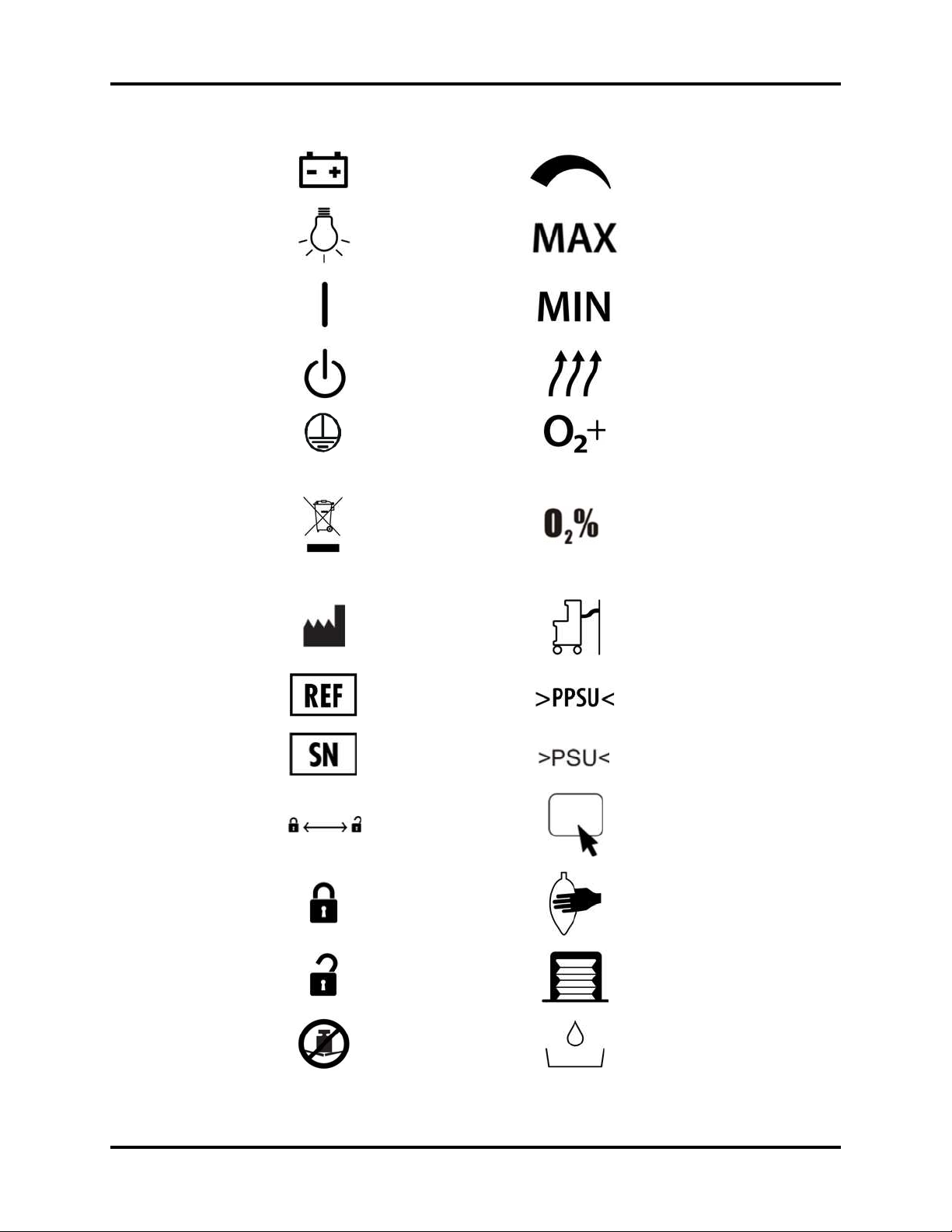
Symbols Introduction
Electrical:
Internal Battery
Electrical:
Light
Electrical:
Power On
Electrical:
Power Standby
Electrical:
Protective Earth
(Ground)
Gas Flow:
Flow Control
Gas Flow: Maximum
Gas Flow: Minimum
Gas Flow Total
Gas:
Flush
O
2
Electrical:
E
WEEE (Waste of
Electrical and
Electronic
Equipment) Marking.
Sensor Connector
O
2
Separate treatment
from general waste at
end of life.
Identifier:
Manufacturer
Gas Pipeline Connection
Identifier:
Manufacturer’s
Reference/Catalog
Material:
Polyphenyl-sulfone
Number
Identifier:
Serial Number
Indicator
Lock/Unlock:
Direction
Lock/Unlock:
Lock
Lock/Unlock:
Unlock
No Heavy Objects
Do Not Crush
Material:
Polysulfone
Tou ch pa d
Manual ventilation via Breathing Bag
Automatic Ventilation
Water Trap
A5/A3™ Operating Instructions 046-003777-00 xix
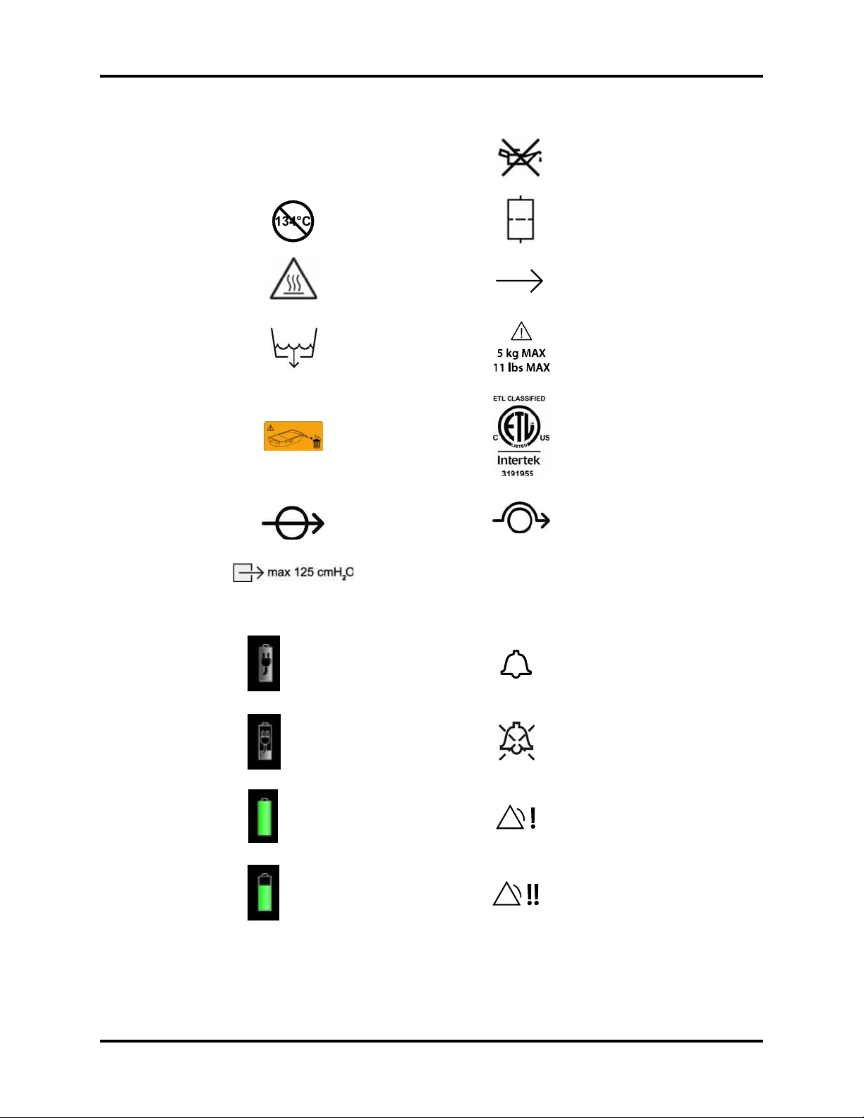
Introduction Symbols
134°C
134°C
Autoclavable
Not Autoclavable
Caution: Hot
Water Drain
Peel off the work
surface protective
film
Canister opened
Do Not Oil
Filter Access
Direction of flow
Drawer weight limit
Conforms to UL std 60601-1, IEC std
60601-2-13
Certified to CAN/CSA std C22.2 No
601.1, No 60601-2-13
Canister closed
Maximum pressure of
ACGO separate outlet
Battery supply fully charged.
AC power connected and
powering system.
Battery supply partially
charged. AC power connected,
charging battery supply, and
power system.
Battery supply fully charged
and powering system. AC
power not connected.
Battery supply partially
charged and powering system.
AC power not connected.
Alarm Icon
Alarm Silence Icon
Low priority message
Medium priority message
xx 046-003777-00 A5/A3™ Operating Instructions

Battery supply low charged
and powering system.
Recharging recommended. AC
power not connected.
High priority message
Battery supply not installed.
Breathing System Warmer Off
A5/A3™ Operating Instructions 046-003777-00 i - xxi

This page intentionally left blank.
i - xxii 046-003777-00 A5/A3™ Operating Instructions

1.0
Product Description
General System Overview ...................................................................................................................................................................1-2
Physical Views .............................................................................................................................................................................................1-8
A5/A3™ Operating Instructions 046-003777-00 1 - 1

General System Overview Product Description
1.1 General System Overview
1.1.1 General Description
The A5/A3 Anesthesia System is a device intended to administer, continuously or intermittently, a
general inhalation anesthetic to a patient, and to maintain a patient's ventilation. The A5/A3 also
provides for ventilatory monitoring of the patient. The anesthesia system is intended to be used in
the patient environment.
The A5/A3 Anesthesia System consists of a main unit (includes an anesthetic ventilator and
flowmeter monitor assembly) and a detachable breathing system. The applied part of the anesthesia
system are breathing tubes and masks.
The A5 Anesthesia System provides the following ventilation modes:
• Volume Control Ventilation (VCV), which includes the Pressure Limit Ventilation (PLV) function
• Pressure Control Ventilation (PCV) with/without Volume Guarantee (VG) ventilation mode
• Synchronized Intermittent Mandatory Ventilation (SIMV ) with VC mode
(with/without PS option)
• Synchronized Intermittent Mandatory Ventilation (SIMV) with PC mode
(with/without PS option)
• Pressure Support (PS) ventilation mode
• Spontaneous ventilation in Manual mode with APL fully open
• Manual Ventilation through the use of a breathing bag
• Cardiac Bypass mode
The A3 Anesthesia System provides the following ventilation modes:
• Volume Control Ventilation (VCV), which includes the Pressure Limit Ventilation (PLV) function
• Pressure Control Ventilation (PCV)
• Synchronized Intermittent Mandatory Ventilation (SIMV ) with VC mode
(with/without PS option)
• Pressure Support (PS) ventilation mode
• Spontaneous ventilation in Manual mode with APL fully open
• Manual Ventilation through the use of a breathing bag
Electronic PEEP is available in all automatic ventilation modes. User control over inspiratory flow
(Tslope) is possible in PCV, SIMV, and PS modes. Automatic fresh gas compensation limits the effect
on the patient ventilation from changes in fresh gas flow rate by the operator. The traditional bellows
system is driven by oxygen and makes patient disconnections clearly visible.
The A5/A3 Anesthesia System provides the following common functions:
• Automatic leak detection
• Circuit gas leakage compensation and automatic compliance compensation
• Cylinder and central pipeline gas supply connections available for gas input
• Electronically displayed flowmeter and electronically adjustable PEEP
• Electronic timer to display the duration between the start and end of an operation
• Work table light
• Mounting rails to connect an external patient monitor
•Network-ready
• Flow trigger mode available for PS and SIMV
• Auxiliary O
•Active AGSS
O cutoff
•N
2
•Vaporizer
and air supply
2
1 - 2 046-003777-00 A5/A3™ Operating Instructions

Product Description General System Overview
• Total flow rotameter
•AG module
1.1.2 Key Features
FEATURE DESC RIPTION
Display 15 inch color LCD with touchscreen
Navigation Graphical user interface for easy navigation
Ventilation Manual and automatic ventilation modes and monitoring: VCV, SIMV-VC,
PCV, SIMV-PC (A5 only), PS, and Manual
Fresh Gas Delivery Continuous and intermittent anesthesia flow, total flow rotameter,
virtual dual flow tubes, electronically displayed on screen for ease of use
3 cylinder mount locations on rear
Breathing System Heated, adjustable swivel, side hose ports, single turn APL valve
Ergonomics Large stainless steel work surface
Adjustable Breathing System block via swivel up to 50 degrees
Electronic PEEP Positive End Expiratory Pressure (PEEP) is set and controlled electronically.
Clear Data Display Two large waveforms for pressure and flow or
Spirometry Loops (A5 only)
USB Mouse Support The A5/A3 system supports a wired USB mouse, which can be plugged into
one of the two SB ports at the rear of the unit. A cursor appears when the
mouse is plugged. The cursor disappears if the user touches the screen or
after 15 seconds of mouse inactivity.
1.1.3 Fresh Gas Dosing
The A5/A3 fresh gas dosing subsystem offers the following features:
• Virtual On-Screen dual flow tube and numerical readouts to display the O
• A knob guard to prevent inadvertent movement of the flow control knobs
• Gas supply gauges to indicate the gas pipeline supply pressures and gas cylinder pressures
• Mechanical total flowmeter to display the combined flow of O
•An O
• A single combined output of auxiliary O
Safety systems within the A5/A3 work to prevent hypoxic mixtures from being delivered to the
patient. Nitrous oxide will not be delivered unless oxygen flow is present. A pneumatic safety system
assures that at least 21% O
is placed in the standby mode, O
WARNING: Ensure that both O2 and N2O flow controllers are turned OFF fully at the
All A5/A3 units are designed to maintain a safe O2:N2O ratio by allowing nitrous oxide to be set to a
flow rate that is proportional to a previously adjusted flow of oxygen. The N
flow of O
to maintain oxygen flow at its previously set level when N
flush button
2
start and at the end of each case.
so that a safe ratio of no less than 21% oxygen can be maintained. The A5/A3 is designed
2
A3: The USB mouse can serve as a backup to the touchscreen.
A5: The USB mouse can serve as a backup to both the touchscreen and
touchpad.
, N2O, and Air flows
2
, Air, and N2O
2
and Air with flowmeters
2
is present when setting mixtures of O2 and N2O. Additionally, if the A5/A3
2
fresh gas flow is not available.
2
O flow is limited by the
2
O is decreased.
2
A5/A3™ Operating Instructions 046-003777-00 1 - 3

General System Overview Product Description
When adjusting N2O and O2 flow rates, always adjust the oxygen flow first to enable the nitrous oxide
flow. To add N2O to the fresh gas flow, open the N2O flowmeter valve, but only after opening the O2
flowmeter valve.
1.1.4 Flow Control
Flow Control needle Valve and Knob:
Three independent flow control knobs allow setting the input flow rates of N
fresh gas flow.
N
O Automatic Cutoff:
2
An N2O automatic cutoff valve stops the flow of N2O if O2 flow is less than 200 mL/min.
O
Pressure Loss Alarm:
2
An O2 pressure loss alarm annunciates when oxygen pressure is less than 220 kPa (32 psi).
Oxygen Ratio Controller:
An O
ratio controller ensures that there is always at least 21% oxygen concentration in the fresh flow
2
when N
O is fully open.
2
O, Air, and O2 into the
2
1.1.4.1 Flow/Pressure Sensing
The Breathing System block contains patient flow and pressure sensors to measure inspiratory flow,
expiratory flow, and inspiratory pressure. These sensors enable spirometry as well as standard
pressure and flow monitoring.
1.1.5 Vaporizer Mounting
The A5/A3 contains a 2-position Selectatec-type vaporizer mounting system to enable anesthetic
agents to be introduced into the fresh gas flow. The mounting system adapts vaporizers with
interlock, which permits only one agent at a time to be administered. Lighting above the vaporizers
enables them to be seen in a darkened environment. A maximum of two vaporizers can be attached
for use at any one time. Halothane, Enflurane, Isoflurane, Desflurane, and Sevoflurane vaporizers can
be used.
For the A5 model, a third, non-functional vaporizer parking spot on the side of the unit is provided as
part of the standard configuration.
1.1.6 Anesthesia Ventilator
The A5/A3 ventilator offers multiple ventilation modes: Volume Control Ventilation (VCV),
Synchronized Intermittent Mandatory Ventilation-Volume Control (SIMV-VC), Pressure Control
Ventilation (PCV), Pressure Support (PS) ventilation, and Manual ventilation.
The A5 offers additional ventilation modes, which include Pressure Control Ventilation (PCV) with and
without Volume Guarantee (VG), and Synchronized Intermittent Mandatory Ventilation-Pressure
Control (SIMV-PC).
1.1.7 Breathing System
A portion of the patient circuit is integrated into an assembly block called the Breathing System. The
system contains a temperature controller, which warms the block to a temperature of 35ºC typical at
20ºC ambient temperature to limit the formation of water condensate. The Breathing System can be
swiveled horizontally up to 50 degrees for user convenience.
The breathing system provides access to the APL valve and breathing bag along with a view of the
airway pressure gauge. The APL valve has a single turn knob that provides a clear view of the manual
breathing pressure setting. The absorber assembly incorporates a cam-lock device that opens and
closes to provide access to the absorber canister. Either a CO
used. Two water traps that can be drained are located on the CO
breathing system block.
1 - 4 046-003777-00 A5/A3™ Operating Instructions
absorbent Pre-Pak or loose fill can be
2
absorber assembly and on the
2

Product Description General System Overview
NOTE: Operating the A5/A3 with a full water trap in the breathing system
Two (2) flow sensors in the breathing system measure inspired and expired gases for control and
monitoring. Inspired oxygen concentration is monitored via a fuel-cell type sensor. Breathing
pressure is monitored with both a PAW gauge (mechanical) and electronic gauge. The breathing
system can be swiveled for ease of positioning. A leak test port is provided to allow for leak testing
during startup.
The main pneumatic components of the Breathing System are as follows:
• Inspiratory Valve (passive)
• Expiratory Valve (passive)
• Airway Pressure Limiting Valve (APL)
• Connection for O
•CO2 Absorber Assembly
• Bellows Assembly
• Auto/Manual bag switch
• Bag arm
•PAW Gauge
The Breathing system connects to the A5/A3 main unit through the following ports:
block does not allow the water to condense appropriately. The trap
should be removed and emptied when filled with water.
Sensor
2
• Drive gas port, designed for use with oxygen as the drive gas
• Fresh gas port
• Exhaust gas port
• Flow sensor pressure transmission pipeline port
The Breathing System contains the following ports for end-user connections:
• Inspiratory port for Inspiratory hose of patient breathing circuit
• Expiratory port for Expiratory hose of patient breathing circuit
• Manual Breathing Bag Arm
• Connection for the O
•Water trap
• Leak test port for sealing the breathing circuit during leak testing
2
cell
1.1.8 Anesthetic Gas Scavenging System (AGSS)
The A5/A3 includes a waste gas scavenger that attaches to the side rail mount on the system. The A5/
A3 provides a port for the connection of the waste line from an anesthetic gas monitor.
1.1.9 Power Management / Battery Supply
The advanced power management system of the A5/A3 provides AC power for main system
functions while charging the system’s internal battery supply. During AC power failure, the A5/A3 will
operate on battery power for a minimum of 75 minutes with one (1) new battery installed (A3) or 150
minutes with two (2) new batteries installed (A5). See ‘‘Battery Power Specifications’’ on page 9-6.
A5/A3™ Operating Instructions 046-003777-00 1 - 5

General System Overview Product Description
A recessed main switch is provided to power the system On and to put the system on power standby
where the battery supply continues to charge as necessary when the A5/A3 is plugged into an
external power source. The main switch also stops the O2 fresh gas supply when the A5/A3 is placed
in Power Standby mode.
Auxiliary AC outlets on the rear of the machine operate independently of the main switch position.
The A5 provides four (4) auxiliary AC outlets; the A3 provides three (3) auxiliary AC outlets. The
auxiliary AC outlets are not powered when operating the A5/A3 on the internal battery supply.
NOTE: Use the battery supply in the A5/A3 at least once every month to
extend battery life. Charge the battery supply before its power capacity
is depleted.
NOTE: Inspect and replace the battery supply at regular service intervals.
NOTE: The operating time of a battery depends on equipment configuration
NOTE: In case of battery failure, contact Mindray service personnel for battery
Long-term battery life depends on how frequent and how long the
battery supply is used. For a properly maintained and stored lithiumion battery, its long-term life expectancy is approximately three (3)
years. In more aggressive usage, life expectancy can be shortened.
Replacing lithium-ion batteries every three (3) years is recommended.
and operation.
supply replacement.
The A5/A3 Anesthesia System is designed to operate on battery power whenever AC power is
interrupted. When the A5/A3 is connected to an AC power source, the battery supply is charged
whether or not the A5/A3 is turned on. In case of power failure, the A5/A3 will automatically switch to
run from the internal battery supply. When AC power source is restored within the specified time, the
battery supply begins recharging, and power is switched from battery to AC automatically to ensure
continuous system use.
When power is lost for less than or equal to 60 s, the alarm settings prior to the power loss shall be
restored automatically.
The on-screen battery symbol indicates the battery status. See FIGURE 1-1:
PART(S) DESCRIPTION
Battery supply is fully charged.
AC power is connected.
The A5/A3 is being powered by AC power. The solid portion
represents the current charge level of the batteries in proportion
to its maximum charge level.
Battery supply is partially charged.
AC power is connected and charging battery supply.
The A5/A3 is being powered by AC power.
Battery supply is fully charged.
AC power is not connected.
The A5/A3 is being powered by internal battery supply.
1 - 6 046-003777-00 A5/A3™ Operating Instructions

Product Description General System Overview
PART(S) DESCRIPTION
Battery supply is partially charged.
AC power is not connected.
The A5/A3 is being powered by internal battery supply.
Battery supply is low charged. Batteries need to be charged
immediately to operate as a safe power backup.
AC power is not connected.
The A5/A3 is being powered by internal battery supply.
Battery supply is not installed.
FIGURE 1-1 Battery Status
If the battery capacity is too low, power supply failure will result. A high-level alarm will be triggered
and the message Low Battery Voltage! will be displayed in the technical alarm area. In this case,
apply AC power to the A5/A3 Anesthesia System to resume operation and charge the battery supply.
1.1.10 Workplace Ergonomics
The A5/A3 is a full-featured anesthesia delivery work station. The raised perimeter of its stainless steel
work surface retains items that might otherwise roll or slide off its edge. The work surface light has
high and low brightness settings. The wrap-around handle enables fine positioning of the machine.
Three (3) large drawers are available for storage. All drawers can be locked with a key. Rail mounts on
both sides of the machine enable mounting of patient monitors and most standard attachment arms
for other devices. For the A5, a non-slip footrest and central brake are provided. For the A3, a non-slip
footrest and individual caster brakes are provided. The top shelf can be used to mount additional
equipment.
The operator of the A5/A3 should be positioned in front of the monitor at a comfortable distance to
view all displayed waveforms, text, and controls.
1.1.11 Hook
There is a hook located on the front of the breathing system that can be used to hang the tubes of
the breathing circuit.
A5/A3™ Operating Instructions 046-003777-00 1 - 7

Physical Views Product Description
1.2 Physical Views
1.2.1 Main Unit (Front View)
A1
A3
A5
A7
A9
A11
A13
A2
A4
A6
A8
A10
A12
A14
A17
A18
A19
A20
A21
A22
A23
A24
A25
A26
A27
A28
A15
A16
FIGURE 1-2 Main Unit (Front View)
PART(S) DESCRIPTION
A1 Alarm Light Illuminates red, yellow, or cyan during an alarm condition
A2 LCD Touchscreen Display /
System Interface
A3 Auxiliary O
A4 Auxiliary O
/Air Flowmeters Auxiliary O2/Air Flowmeters for auxiliary O2/Air output
2
/Air Gas Outlet Nozzle (barbed connector) for auxiliary O2/Air output.
2
to indicate the alarm priority. Red = high priority,
Yellow = medium priority, cyan = low priority,
off = no alarm condition.
See section ‘‘System Interface’’ on page 3-1
Combines the auxiliary O
output of O
upon the O
only, Air only, or O2/Air blend, depending
2
and Air flow adjustments.
2
/Air flowmeters into a single
2
1 - 8 046-003777-00 A5/A3™ Operating Instructions

Product Description Physical Views
PART(S) DESCRIPTION
A5 Auxiliary O2 Gas Power Outlet
(A5 only)
A6 Flow Control Knobs N
A7 Pressure Gauges (pipeline) Indicate the pressure at pipeline inlets for O
A8 Pressure Gauges (cylinder) Indicate the pressure at cylinder inlets for O
A9 Total Flow Meter Displays the combined flow rate of O
A10 O
A11 O
Sensor Electrical Port Connects the O2 sensor cable on the breathing system to
2
Flush Button Provides high flow O2 to the inspiratory limb of the
2
A12 Touchpad
High pressure O2 outlet (DISS connector) for connecting
external devices such as a jet ventilator.
O, Air, and O2 gas dosing. Turn each knob
2
counterclockwise to increase flow.
, Air, and N2O.
2
, Air, and N2O.
2
, Air, and N2O.
2
the main A5/A3 unit.
breathing system.
Allows alternate control of the touch screen. Pull out to use.
(A5 only)
A13 AGSS Anesthetic Gas Scavenging System
A14 Wheel Lock
(A5 only)
Locks or releases the brakes for all wheels when depressed.
A wheel lock indicator displays red to indicate that the
wheels are locked. Green indicates unlocked.
A15 Wheel Lock Indicator
(A5 only)
Displays a lock symbol in red background to indicate the
wheels are locked, or an unlock symbol in green
background to indicate the wheels are unlocked.
A16 Wheels Casters to enable the A5/A3 System to be moved. Casters
on the A5 lock via a central brake. Casters on the A3 lock via
individual locking levers on each caster.
A17 Work Light Located under the top shelf to illuminate the work level
shelf and allow the user to read the vaporizer dial setting in
a darkened room.
A18 Work Light Switch Turns on/off the work light. Three settings: Off, Low, and
High. The user can turn on the work light only when the
main power switch is turned on.
A19 Vaporizer Mounting Manifold /
Mounting Bar
An interface for two Selectatec-type vaporizers to mount in
this location. Bar holds two vaporizers. An interlock within
the vaporizers provides for use of one vaporizer to deliver
one agent at a time.
A20 Vaporizer Mount Valve
Vaporizer index and outlet ports.
Cartridge
A21 Vaporizer Parking Spot Holds a non-functional vaporizer for user convenience.
(A5 standard, A3 optional)
A22 Vaporizer Locking Device Vaporizer locking mechanism to secure against accidental
disconnection
A23 AC Status LED Illuminated when the system is connected to an AC power
source.
A24 Battery Charging LED Illuminated when the battery supply is charging.
A25 Main Power Switch Switch to turn the system on or off.
A26 Handle Metal bar used to assist moving the A5/A3
A27 Key lock Key and lock for securing the drawers
A28 Storage Drawers Drawers (3) for storage (lockable)
A5/A3™ Operating Instructions 046-003777-00 1 - 9

Physical Views Product Description
1.2.2 Main Unit (Rear View)
B9
B5
B13
B1
B8
B6
B2
B3
B4
B7
B10
B11
B12
B14
FIGURE 1-3 Main Unit (Rear View)
PART(S) DESCRIPTION
B1 Circuit Breakers Breakers for each auxiliary outlet
A5: 3 A each (quantity 4), 10 A total (quantity 1)
A3: 3 A each (quantity 3)
B2 Mains Inlet Connects the mains power cord
B3 Exhaust Fan Forces air to cool electronics and prevent buildup of O
concentration. Do not block.
2
1 - 10 046-003777-00 A5/A3™ Operating Instructions

Product Description Physical Views
PART(S) DESCRIPTION
B4 Communication Ports SP1, DP1, CS1, SB1, SB2 (See section 9.6.4 (pg. 9-7)
"Communication Ports".)
CAUTION: Do not connect any
devices to the SB ports
other than Mindray
approved USB storage
devices and a supported
USB mouse (see
‘‘N etworking and USB
Storage’’ on page A-4).
B5 Auxiliary AC Outlets A5: Additional devices up ‘to a total maximum power of 10
amps can be connected to four (4) outlets.
A3: Additional devices up to a total maximum power of 9
amps can be connected to three (3) outlets.
The A5 outlets are covered with two (2) metal plates, the A3
outlets are covered with one (1) metal plate, and require a
tool to access. Only authorized personnel can access these
outlets.
B6 Equipotential stud / lug Provides a ground point
B7 Hooks Allows user to hang or wrap cords
B8 Cylinder Supply Connections Interface connectors to high pressure supply tanks (O
O)
and N
2
B9 Gas Pipeline Supply
Connections
Connections for O
, Air, and N2O from a pipeline gas supply
2
, Air,
2
B10 Sample Line Exhaust Gas Inlet Inlet for exhaust gas from gas module. Merges with the
AGSS connector that connects to the AGSS.
B11 AGSS Connector Connects the AGSS or waste gas disposal system
B12 AGSS Anesthetic Gas Scavenging System
B13 Cylinders Supply tanks (E-size) containing high pressure O
N
O to act as backup supply if the pipeline pressure is
2
removed. Note: Tanks not supplied by Mindray.
, Air, and
2
B14 AGSS Transfer Hose Routes exhaust gases from main unit to scavenger.
A5/A3™ Operating Instructions 046-003777-00 1 - 11

Physical Views Product Description
1.2.3 Main Unit (Left View)
C4
C5
C1
C2
C3
FIGURE 1-4 Main Unit (Left View)
PART(S) DESCRIPTION
C1 Auxiliary O
Flowmeters
C2 Auxiliary O
Outlet
C3 Auxiliary O
Power Outlet
/Air
2
/Air Gas
2
Gas
2
Auxiliary O2/Air Flowmeters for auxiliary O2/Air output
Nozzle (barbed connector) for auxiliary O2/Air output. Combines the
auxiliary O
High pressure O
devices such as a jet ventilator.
/Air flowmeters into a single output.
2
outlet (DISS connector) for connecting external
2
(A5 only)
C4 Rail Mount Enables mounting of patient monitors and most standard attachment
arms for other devices. Rail mounts are on both left and right sides of
the A5/A3.
C5 Module slot AG module can be inserted into the slot and identified.
1 - 12 046-003777-00 A5/A3™ Operating Instructions

Product Description Physical Views
1.2.4 Main Unit (Right View)
D1
D2
D3
D4
FIGURE 1-5 Main Unit (Right View)
PART(S) DESCRIPTION
D1 Vaporizer Mounting
Manifold / Mounting Bar
D2 Key Lock Key and lock for securing the drawers
D3 Storage Drawers Drawers (3) for storage (lockable)
D4 Rail Mount Enables mounting of patient monitors and most standard
An interface for two Selectatec-type vaporizers to mount in
this location. Bar holds two vaporizers. An interlock within
the vaporizers provides for use of one vaporizer to deliver
one agent at a time.
attachment arms for other devices. Rail mounts are on both
left and right sides of the A5/A3.
A5/A3™ Operating Instructions 046-003777-00 1 - 13

Physical Views Product Description
1.2.5 Main Unit (Top View)
E1
E2
Rear
E4
E3
Front
FIGURE 1-6 Main Unit (Top View)
PART(S) DESCRIPTION
E1 Top Shelf Top level surface
E2 Work Level Shelf Work Level surface (stainless steel)
E3 Handle Wrap-around metal bar used to assist moving the A5/A3
E4 Mounting Holes Allows mounting of optional equipment to the top shelf
device
(e.g., DPM6 and DPM7 mounting plates and kits. See
section A.7 (pg. A-4) "Mounting Accessories")
1 - 14 046-003777-00 A5/A3™ Operating Instructions

Product Description Physical Views
1.2.6 Breathing System (Top View)
F1
F2
F3
F4
F5
F6
F7
F8
F10
F9
FIGURE 1-7 Breathing System (Top View)
PART(S) DESCRIPTION
F1 Bellows (including bellows
F2 PAW Gauge
dome)
1
2
F3 Expiratory Limb Exhaled breathing circuit connection
F4 Inspiratory Limb Inhaled breathing circuit connection
F5 Expiration Valve Allows flow of expiratory gas from the patient to the re-
F6 Inspiration Valve Allows flow of inspiratory gas to the patient, and prevents
F7 Bag Arm Provides the interface to the manual ventilation bag
F8 O
F9 APL (Airway Pressure
Sensor Cable Assembly An electro-galvanic fuel cell device to measure the
2
Limiting) Valve
2
Bellows that separates the breathing system gases from the
oxygen drive gas
Indicates the patient airway pressure
breathing system, and prevents reverse flow.
reverse flow.
concentration of O
cable, O
cell cover, and O2 sensor.
2
. The assembly is composed of the O2
2
Rotary regulator for setting the breathing system pressure
limit during manual ventilation. Its scale shows approximate
pressure. Set to SP during Spontaneous breathing.
A5/A3™ Operating Instructions 046-003777-00 1 - 15

Physical Views Product Description
PART(S) DESCRIPTION
F10 Auto/Manual Bag Switch Enables switching between Automatic and Manual
ventilation modes
1
The bellows dome is a transparent cover with graduation marks from 300 to 1500 mL. These marks are
for reference only. Tidal volume (Vt) should be read exclusively from the display of the user interface.
Delivered Vt is a combination of bellows displacement and fresh gas flow.
2
The APL valve and Paw gauge numerics are for reference only. Calibrated patient airway pressure is displayed on the user interface.
1 - 16 046-003777-00 A5/A3™ Operating Instructions

Product Description Physical Views
1.2.7 Breathing System (Left View)
G6
G5
G4
G1
G3
G2
FIGURE 1-8 Breathing System (Left View)
PART(S) DESCRIPTION
G1 CO
G2 Condensate Drain Valve Turn counter-clockwise (looking from bottom) to drain water
G3 Absorber Canister Lock Lever-type locking mechanism to lock (horizontal position) or
G4 Water Trap Accumulates condensate from the breathing system. Must be
G5 Absorber Bypass Assembly Maintains pressure in the breathing circuit when changing
G6 Hook Hang the tubes of the breathing system.
Absorber Canister Container for CO2 absorbent material loose fill or Pre-Paks)
2
collected in the absorber canister.
unlock (vertical position) the absorber canister from the
canister assembly.
removed and emptied periodically. To remove, turn clockwise
(looking from top).
the sodalime contents in the CO
absorber canister.
2
A5/A3™ Operating Instructions 046-003777-00 1 - 17

Physical Views Product Description
1.2.8 Anesthetic Gas Scavenging System (AGSS) (Top, Right, and
Rear Views)
Top Vie w
H1
Right View
H5
Max
Min
FIGURE 1-9 AGSS (Top, Right, and Rear Views)
Rear View
H2
H3
Max
Min
H4
PART(S) DESCRIPTION
H1 Mounting Rail Attachment Allows the AGSS to be mounted on the side rail. Contains a
H2 Flow Adjust Knob Turn clockwise or counter-clockwise to adjust the flow in the
H3 Exhaust Port Exhaust port to the hospital’s waste gas scavenging system
H4 Inlet Port Intake for exhaust gases from the breathing system. An AGSS
H5 Float Indicates exhaust flow. Adjusted by turning the Flow Adjust
thumbscrew that must be tightened against the mounting
rail.
AGSS until the float is between Min and Max marks.
transfer hose connects the Inlet and AGSS ports (see
FIGURE 1-3) to transfer the exhaust gases.
Knob (H2) until the float is between the Min and Max marks.
1 - 18 046-003777-00 A5/A3™ Operating Instructions

2.0
Installation
Unpacking..................................................................................................................................................................................................... 2-3
Initial Setup................................................................................................................................................................................................... 2-4
Install the Vaporizer................................................................................................................................................................................. 2-5
A5/A3™ Operating Instructions 046-003777-00 2 - 1

Installation
WARNING: This equipment must be installed by a factory authorized
representative.
WARNING: Continuous use of desiccated sodalime may endanger patient safety.
Adequate precautions should be taken to ensure that the sodalime in
the CO
absorbent canister does not become desiccated. Turn off all
2
gases when finished using the system.
WARNING: When electrosurgical equipment is used, keep the electrosurgical leads
away from the breathing system, the O
A5/A3 Anesthesia System. Keep available backup manual ventilation
sensor, and other parts of the
2
and a respirator with mask in case the electrosurgical equipment
prevents safe use of the ventilator. Ensure the correct operations of all
life support and monitoring equipment.
WARNING: Do not use masks or breathing tubes that are antistatic or conductive.
They can cause burns if they are used near high frequency
electrosurgical equipment.
WARNING: This A5/A3 Anesthesia System has waste gas exhaust ports. The
operator of the machine should pay attention to the disposal of the
residual breathing gas scavenged.
CAUTION: The operational environment and the power source of the equipment
must comply with the requirements as specified in the A5/A3 ‘‘Product
Specifications’’ on page 9-1
2 - 2 046-003777-00 A5/A3™ Operating Instructions

Installation Unpacking
2.1 Unpacking
When the A5/A3 Anesthesia System is delivered, IMMEDIATELY inspect the box for any damage.
a. If there is NO damage and ALL tip indicators on the box exterior are intact, then sign and
date the bill of lading or airway bill to indicate safe receipt of the A5/A3.
b. If there is DAMAGE or ANY of the tip indicators on the box exterior have been activated,
then conditionally accept the delivery and clearly describe the damages on the bill of
lading or airway bill. BOTH the carrier and recipient must sign and date the bill of lading
or airway bill. Save all damaged factory packaging until further instructed by Mindray.
The receiver should immediately contact Mindray Customer Service at (800) 288-2121 or
(201) 995-8000.
A5/A3™ Operating Instructions 046-003777-00 2 - 3

Initial Setup Installation
2.2 Initial Setup
The initial setup of the A5/A3 Anesthesia System must be performed by an authorized Mindray
service representative. Please contact Mindray Technical Support for any additional assistance.
NOTE: The A5/A3 is intended to be operated with an external CO2 monitor
complying with ISO 21647. Connection to the CO2 monitor should be
via a sample line from the patient circuit.
2 - 4 046-003777-00 A5/A3™ Operating Instructions

Installation Install the Vaporizer
2.3 Install the Vaporizer
CAUT ION: O nly vap orizers wit h Selectate c Inter lock Sys tems may be u sed wit h the
A5/A3 unit.
WARNING: Use vaporizers compliant to ISO 8835-4. See section A.9 (pg. A-5)
"Vaporizers". Refer to the vaporizer manufacturer’s Instructions For Use
for mounting, filling, or draining the vaporizer and other information.
WARNING: Use care in lifting and manipulating vaporizers during the mounting
NOTE: The barometric pressure may differ from the calibration pressure of the
process as their weight may be greater than expected, based on their
size and shape.
anesthetic vaporizer. This may cause an inaccurate output of the
anesthetic agent. The operator should continuously monitor the
concentration of anesthetic agent during system use to determine if
the outputted concentration is accurate.
FIGURE 2-1 shows the location of the vaporizer mounting system on the A5/A3 unit.
Vaporizer mounts for two
inline vaporizers
A5 only: Additional
vaporizer mount for one
inactive vaporizer
FIGURE 2-1 Location of Vaporizer Mounting System
1. If replacing and removing the vaporizer, lift each vaporizer straight up off the manifold. Do
not pull the vaporizer forward. Do not rotate the vaporizer on the manifold.
2. Align the new vaporizer over the valve cartridges of the mounting bar, slightly tilting back
the vaporizer. Hang the vaporizer on the mounting bar as shown in FIGURE 2-2. Ensure that
the locking mechanism handle is in the unlocked position. Ensure that the dial is in the “T”
(Transport) position or equivalent, depending upon the vaporizer manufacturer’s
Instructions For Use.
A5/A3™ Operating Instructions 046-003777-00 2 - 5

Install the Vaporizer Installation
Locking Mechanism
Handle in the
Unlocked Position
Vaporizer dial in the
“T” position
FIGURE 2-2 Vaporizer, Unlocked
3. Rotate the locking mechanism handle clockwise into the locked position as shown in
FIGURE 2-3.
NOTE: If installing a Desflurane vaporizer, refer to the manufacturer’s
Instructions For Use on installation and use of the vaporizer.
Locking Mechanism
Handle in the Locked
FIGURE 2-3 Vaporizer, Locked
4. Final check:
1. Ensure that the top of the vaporizer is horizontal. If not, remove and reinstall the vaporizer.
2. If a vaporizer lifts off the manifold, repeat steps 1 through 3 to reinstall the vaporizer. If the
vaporizer lifts off a second time, do not use the system.
WARNING: For the A5/A3 Anesthesia System, using or turning on more than one
vaporizer simultaneously is prohibited and prevented by a mechanical
interlock. Do not attempt to override this safety mechanism.
2 - 6 046-003777-00 A5/A3™ Operating Instructions

Installation Install the Vaporizer
2.3.1 Filling and Draining the Vaporizer
Install the vaporizers with a selectatec interlock system that are compliant to ISO 8835-4 on the
A5 unit. See section A.9 (pg. A-5) "Vaporizers". Refer to the manufacturer’s vaporizer Instructions
For Use for filling or draining the vaporizer and other information.
WARNING: Ensure that the correct anesthetic agent is used. The vaporizer is
designed with the specific anesthetic agent named on it and further
indicated by color coded labelling. The concentration of the anesthetic
agent actually output will vary if the vaporizer is filled with the wrong
agent.
WARNING: Do not reuse the agent drained from the vaporizer. Treat as a hazardous
chemical and follow local regulations for proper disposal.
A5/A3™ Operating Instructions 046-003777-00 2 - 7

Install the Vaporizer Installation
This page intentionally left blank.
2 - 8 046-003777-00 A5/A3™ Operating Instructions

3.0
System Interface
Main Screen Components ..................................................................................................................................................................3-2
System Information Header ............................................................................................................................................................... 3-6
Fresh Gas Flow Display.......................................................................................................................................................................3-10
Waveforms Tab........................................................................................................................................................................................ 3-11
Spirometry Tab (A5 Only)..................................................................................................................................................................3-13
Demographics Tab................................................................................................................................................................................ 3-17
Ventilation Mode Tabs........................................................................................................................................................................3-19
Measured Values Area.........................................................................................................................................................................3-21
System Softkeys......................................................................................................................................................................................3-22
Setup ............................................................................................................................................................................................................. 3-29
General Tab................................................................................................................................................................................................3-29
Display Tab.................................................................................................................................................................................................3-31
System Tab.................................................................................................................................................................................................3-34
Service Tab................................................................................................................................................................................................. 3-40
A5/A3™ Operating Instructions 046-003777-00 3 - 1

Main Screen Components System Interface
3.1 Main Screen Components
The components of the Main screen are shown in FIGURE 3-1.
12
7
5
3
2
1
4
6
8
9
11
10
15
13
FIGURE 3-1 A5 Main Screen Components
14
3 - 2 046-003777-00 A5/A3™ Operating Instructions

System Interface Main Screen Components
10
8
5
3
2
1
4
7
9
12
11
13
14
FIGURE 3-2 A3 Main Screen Components (without AG gas module connected)
NUMBER
1 Elapsed Timer Displays elapsed time. Select to start, stop, or reset the
2 Fresh Gas Flow Area Displays real-time flowmeter levels for N
3 Patient Size Displays the currently selected patient size (Adult,
4 Current Ventilation Mode Displays the current ventilation mode (VCV, SIMV-VC, PCV,
5 Waveforms Tab See “Waveforms Tab” on page 3-11.
6 Spirometry Tab A5 only. See “Spirometry Tab (A5 Only)” on page 3-13.
7 Demographics Tab See “Demographics Tab” on page 3-17.
* Monitor mode is only available with the AG module.
**SIMV-PC and Bypass are only available on A5.
MAIN SCREEN
COMPONENT DESCRIPTION
timer.
Pediatric, or Infant). Select to change the patient size when
the A5/A3 is in Standby mode, Manual mode or Monitorl*
mode
SIMV-PC*, PS, Manual, Bypass**,Monitor or Standby.
O, Air, and O2.
2
)
A5/A3™ Operating Instructions 046-003777-00 3 - 3

Main Screen Components System Interface
NUMBER
8 Alarm / Prompt Message
COMPONENT DESCRIPTION
Displays physiological alarms, technical alarms, and
Area
prompt messages. The most recent highest priority alarm is
displayed at the top.
The remaining alarms are displayed in the lower area and
grouped by priority. The most recent of these alarms is
displayed first. Select this area to display a list of all active
alarms.
See ‘‘Alarms and Messages’’ on page 6-1 for tables that list
the individual messages and their associated priority levels.
High priority messages are red. Medium priority messages
are yellow. Low priority messages are cyan. Prompt
messages are black text on white background.
9 Alarm Silence Icon Displays the alarm silence icon and Alarm Silence
countdown timer for 120 seconds when the Silence softkey
is selected.
MAIN SCREEN
10 Breathing System Warmer Icon Indicates the warmer is not active.
11 System Date and Time Displays the current system date and time. Select to adjust
the date and time. See ‘‘Date and Time’’ on page 3-8.
12 Main Power Supply and
Battery Status Icon
13 Ventilations Mode and
Setting Parameters Area
Displays the main power supply and battery state. See
“Power Management / Battery Supply” on page 1-5.
Displays tabs for all ventilation modes (VCV, SIMV-VC, PCV,
SIMV-PC*, PS, Manual/Bypass*or Monitor). Each tab
displays the ventilation mode and its parameters. Select a
tab and the “Set Mode” softkey to change the ventilation
mode. Select a parameter button to change the parameter
setting. See ‘‘Ventilation Modes’’ on page 5-7.
* Monitor mode is only available with the AG module.
**SIMV-PC and Bypass are only available on A5.
3 - 4 046-003777-00 A5/A3™ Operating Instructions

System Interface Main Screen Components
NUMBER
14 System Softkeys Setup – Select to open the Setup menu. The Setup menu
MAIN SCREEN
COMPONENT DESCRIPTION
contains the General tab, Display tab, System tab, and
Service tab.
Alarms – Select to open the Alarms menu to set alarm
limits, set alarm volume, and view all active alarms.
Silence – Select Silence softkey to silence all currently
sounding alarm tones. The alarm will sound if a new alarm
occurs.
If the silenced alarms contain middle or high level alarms,
the alarm audio will be paused for 120 seconds.The alarm
silence icon and 120 second countdown time appear at the
top of the screen. Select again to resume the alarm audio.
Note, however, the alarm will sound if that a new alarm
occurs while the system is in an audio-paused state. If this
occurs, you can select the Silence softkey again to silence
the new alarm and reset the silence countdown timer to
120 seconds.
Found in software version 03.04.00 and later
If the silenced alarms are only low level alarms, the alarm
audio will be turned off till there is a new alarm occurs.
Note, however, the alarm will sound if that a new alarm
occurs while the system is in an audio-off state. If the new
alarm is low level alarm, you can select the Silence softkey
again to turn off the new alarm audio. If the new alarm is
medium or high level alarm, you can select the Silence
softkey again to silence the new alarm for 120 seconds.
Found in software version 03.02.00 and later
History - Select to open the History menu. The History
menu contains the List Trends and Event log.
Capture Event - Select to capture an event and log it in the
event log.
15 Gas Area Displayed when AG module is connected. Displays real-
time inspiratory and expiratory levels of gas.
* Monitor mode is only available with the AG module.
**SIMV-PC and Bypass are only available on A5.
A5/A3™ Operating Instructions 046-003777-00 3 - 5

System Information Header System Interface
3.2 System Information Header
3.2.1 Elapsed Timer
Displays the elapsed time. Located at the top left of the main screen. Select to start, stop, or reset the
timer. (FIGURE 3-3)
Elapsed Timer
FIGURE 3-3 Elapsed Timer (with AG module connected)
3.2.2 Patient Size
Displays the currently selected patient size (Adult, Pediatric, or Infant). Select to change the patient
size when the A5/A3 is in Standby mode, Manual mode or Monitor mode (available with the AG
module). (FIGURE 3-4)
Patient Size
FIGURE 3-4 Patient Size Menu (with AG module connected)
3.2.3 Alarm and Prompt Messages
Displays physiological alarms, technical alarms, and prompt messages. The most recent highest
priority alarm is displayed at the top.
The remaining alarms are displayed in the lower area and grouped by priority. The most recent of
these alarms are displayed first.
Select this area to display a list of all active alarms. See ‘‘Alarms and Messages’’ on page 6-1 for tables
that list the individual messages and their associated priority levels. High priority messages are red.
Medium priority messages are yellow. Low priority messages are cyan. Prompt messages are black
text on white background. (FIGURE 3-5)
3 - 6 046-003777-00 A5/A3™ Operating Instructions

System Interface System Information Header
FIGURE 3-5 Alarm and Prompt Messages
3.2.4 Alarm Silence Icon
The Alarm Silence icon and Alarm Silence countdown timer are displayed after selecting the Silence
softkey is selected, which indicates that all currently sounding alarms are silenced for 120 seconds.
(FIGURE 3-6)
Alarm Silence Icon
FIGURE 3-6 Alarm Silence Icon (with AG module connected)
A5/A3™ Operating Instructions 046-003777-00 3 - 7

System Information Header System Interface
3.2.5 Date and Time
Displays the current system date and time. (FIGURE 3-7)
Date and Time
FIGURE 3-7 Date and Time Icon (with AG module connected)
To adjust the date and time:
1. Select the Date and Time icon. The Date/Time dialog is displayed (FIGURE 3-8).
2. Use the dialog keypad and softkeys to adjust the date, time, 12/24 hour format, date format,
and daylight savings time.
NOTE: If applicable, select Daylight Savings Time first before all other
settings.
NOTE: If the Daylight Savings Time On/Off button in the Date/Time
dialog (see Figure 3-8) is disabled and cannot be selected, it is
because the Daylight Savings setting has been set to Auto in
the System settings (see Table 3-9, “System tab settings,” on
page 35).
3. Select the “Accept” to finalize your changes.
FIGURE 3-8 Date and Time Menu
3 - 8 046-003777-00 A5/A3™ Operating Instructions

System Interface System Information Header
3.2.6 Battery Status
Displays the main power supply and battery state (FIGURE ). For more information on the advanced
power management system of the A5/A3, see “Power Management / Battery Supply” on page 1-5.
Battery Status Icon
FIGURE 3-9 Battery Status Icon (with AG module connected)
PART(S) DESCRIPTION
Battery supply is fully charged.
AC power is connected.
The A5/A3 is being powered by AC power. The solid portion
represents the current charge level of the batteries in proportion
to its maximum charge level.
Battery supply is partially charged.
AC power is connected and charging batteries.
The A5/A3 is being powered by AC power.
Battery supply is fully charged.
AC power is not connected.
The A5/A3 is being powered by internal batteries.
Battery supply is partially charged.
AC power is not connected.
The A5/A3 is being powered by internal batteries.
Battery supply is low charged. Batteries need to be charged
immediately to operate as a safe power backup.
AC power is not connected.
The A5/A3 is being powered by internal batteries.
Battery supply is not installed.
FIGURE 3-10 Battery Status
A5/A3™ Operating Instructions 046-003777-00 3 - 9

Fresh Gas Flow Display System Interface
3.3 Fresh Gas Flow Display
Displays real-time flowmeter levels for N2O, Air, and O2. (FIGURE 3-11)
The flowmeter numerics display a precision to two decimal digits for flows < 1 L/min and one
decimal digit for flows ≥ 1 L/min.
For the A5, the size (height) of the fresh gas flow tubes changes depending on whether the AG
module is connected as shown in FIGURE 3-11.
Fresh Gas Flow Display
FIGURE 3-11 Fresh Gas Flow Display
3 - 10 046-003777-00 A5/A3™ Operating Instructions

System Interface Wav eforms Tab
3.4 Waveforms Tab
Displays PAW , Flow, Volume, and CO2 waveforms. (FIGURE 3-12)
Waveforms Tab
FIGURE 3-12 Main Screen Waveforms Tab (with AG module connected)
3.4.1 Waveform Color
WAVEFORM COLO R DESCRIPTIO N
Orange
Cyan
White
Purple
TABLE 3- 1 Waveform color
A5/A3™ Operating Instructions 046-003777-00 3 - 11
Indicates the color of the Paw waveform.
Indicates the color of the Volume and Flow waveform.
Indicates the color of the CO2 waveform.
During the inspiratory phase, Paw and Flow waveforms change to
purple when spontaneous breath is detected in ventilation modes
that contain pressure support.

Wav eforms Tab System Interface
3.4.2 Waveforms Autoscaling
If the measured value of Paw or Flow is larger than the boundary at the end of breath cycle, the
system will auto scale the Paw or Flow at the beginning of the next breath cycle.
If the measured value of Paw or Flow is less than the boundary minus a margin at the end of two
continuous breath cycles, the A5/A3 System will auto scale the Paw or Flow at the beginning of next
breath cycle.
Paw scale:
The margin will be 10 cmH
pressure
≥ 30 cmH2O.
O. For software version 03.02.00 and later, the margin will be 10 cmH2O if
2
For software version 03.02.00 and later, the margin will be 3 cmH2O if pressure
Flow scale:
• The margin will be 10 L/min if Flow ≤ 30 L/min
• The margin will be 15 L/min if Flow > 30 L/min
Volume scale:
• The margin will be 25mL if volume ≤
100 mL
• The margin will be 100 mL if volume > 100 mL
CO
scale:
2
The CO2 scale options are shown in the table below:
CO2 UNIT OF MEASURE SCALE
mmHg
kpa
%
TABLE 3- 2 CO
Scale
2
0-40 0-60 0-80
0.0-5.0 0.0-8.0 0.0-10.0
0.0-5.0 0.0-8.0 0.0-10.0
<30 cmH2O.
3 - 12 046-003777-00 A5/A3™ Operating Instructions

System Interface Spirometry Tab (A5 Only)
3.5 Spirometry Tab (A5 Only)
Displays separate looped graphs of Pressure-Volume (FIGURE 3-13) and Flow-Volume (FIGURE 3-14).
Spirometry Tab
FIGURE 3-13 Spirometry: Pressure-Volume Loop (with AG module connected)
FIGURE 3-14 Spirometry: Flow-Volume Loop (with AG module connected)
A5/A3™ Operating Instructions 046-003777-00 3 - 13

Spirometry Tab (A5 Only) System Interface
Spirometry loops reflect patient lung function and ventilation. They also indicate other related
parameters such as compliance, over-inflation, breathing system leak, and airway blockage.
The system provides two spirometry loops: P-V (Paw-volume) loop and F-V (flow-volume) loop. Data
of P-V and F-V loops come from pressure and flow data. Only one loop is displayed at a time.
The spirometry tab displays four softkeys: Loop Type, Show Reference, Save Loop, and Review Loops.
3.5.1 Loop Type
The Loop Type selection is used to select Pressure - Volume loop or Flow - Volume loop to display on
the spirometry screen. Default Loop Type is Pressure - Volume loop.
Show Reference
Loop Type
FIGURE 3-15 Spirometry Softkeys: Loop Type, Show Reference, Save Loop, and Review Loops
3.5.2 Show Reference
The Show Reference softkey can be selected only after a baseline has been saved via the Save Loop
softkey.
The Show Reference softkey (FIGURE 3-15) is used to select and display a saved Baseline loop,
Reference loop, or no loop (Off ) in the Spirometry Loop Window, overlapped with the currently
plotting loop. Only the four most recently saved reference loops are listed chronologically.
Review Loops
Save Loop
When a Reference loop or Baseline loop is selected to display in the Spirometry Loop Window, the
time stamp will also be displayed.
3.5.3 Save Loop
Select the Save Loop softkey (FIGURE 3-15) to save the currently plotting loop (including its numeric
data) as either a baseline loop or reference loop. Only one baseline loop and up to four reference
loops can be saved. Additional plotting loops can be saved to replace the baseline loop or reference
loops. Only the four most recent reference loops are saved.
The saved baseline or reference loop can be reviewed with its numeric data (via Review Loops
softkey) or displayed with the currently plotting loop on the same graph for comparison (via Show
Reference softkey).
NOTE: A reference loop cannot be saved without first saving a
baseline loop. The A5 system will always make the first saved
loop as the baseline loop if no previous loops have been saved.
Afterward, additional loops can be saved either as a baseline
replacement or as a new reference loop.
3 - 14 046-003777-00 A5/A3™ Operating Instructions

System Interface Spirometry Tab (A5 Only)
To save a baseline loop:
1. From the main screen, select Spirometry tab > Save Loop softkey.
If there is no baseline loop saved in memory, the currently plotting loop will be saved
automatically as the baseline loop.
2. If a baseline loop is already saved in memory, a dialog box will appear with the choices of
“Baseline“ and ”Reference“. S el ect ” Baseline”. A confirmation dialog will be displayed with
the text “Selecting Yes will replace the currently saved Baseline loop. Do you want to
proceed?” If “Ye s ” is selected, the currently saved baseline loop will be replaced. If “No” is
chosen, the save will be aborted.
To save a reference loop:
1. From the main screen, select Spirometry tab > Save Loop softkey. If a baseline loop is
already saved in memory, a dialog box will appear with the choices of "Baseline" and
"Reference". Select "Reference".
A maximum of four (4) sets of Reference loops plus one (1) Baseline loop and corresponding numeric
data can be saved.
When the maximum of four (4) loops is reached, and the user attempts another save, a confirmation
dialog will be displayed with the following text, “Selecting Yes will replace the oldest reference
loop. Do you want to proceed?” If “Ye s” is chosen, the oldest data will be removed as the new data
is added. If "No" is chosen, the save will be aborted.
3.5.4 Review Loops Button
Selecting the Review Loops softkey (FIGURE 3-15) displays the Review Loops screen (FIGURE 3-16).
The following areas and selections are displayed:
Small Loop Windows: These small graphic windows show the baseline and reference loops. The
baseline loop (only one) is always located on the left and has a white border around its graph. The
reference loops (up to four) are located to the right of the baseline loop. The reference loops are
displayed from oldest (left) to newest (right).
The baseline loop information is displayed below the small baseline loop window. The reference loop
information is displayed in cyan highlight for the reference loop that is selected.
Large Loop Window: This graphic window shows an enlarged view of the selected reference loop
overlapped with the baseline loop.
Loop Type: The Loop Type selection is used to choose the type of loop to review. The choices are:
Pressure-Volume and Flow Volume. Default Loop Type is Pressure - Volume loop.
Delete Loop: The Delete Loop selection is used to delete a selected Reference loop. When a
reference loop is deleted, the newer reference loops will shift to the left. The Delete Loop button will
be disabled (grayed out) if no reference loops have been saved. The baseline loop cannot be deleted.
It can only be replaced by another baseline loop.
A5/A3™ Operating Instructions 046-003777-00 3 - 15

Spirometry Tab (A5 Only) System Interface
Non-selected
Baseline Loop
Numeric Data
Area
Non-selected
Reference Loop
Selected Reference
Loop (small)
Non-selected Reference
Loop
Selected
Reference
Loop (large)
FIGURE 3-16 Review Loops window
Numeric Data Area: Displays the numerical data associated with a saved Baseline loop and saved
Reference loops. The parameters listed in column form include: Time, Expiratory Minute Volume
(Mv Exp), Inspiratory Minute Volume (Mv Insp), Expiratory Tidal Volume (Vt Exp), Inspiratory
Tidal Volume (Vt Insp), Ratio of Inspiratory time to Expiratory time (I:E), Positive End
Expiratory Pressure (PEEP), Rate, Peak Inspiratory Pressure (PEAK), Plateau Pressure (PLAT),
Mean Pressure (MEAN), Dynamic Airway Compliance (Compl), and Airway Resistance (Raw).
3 - 16 046-003777-00 A5/A3™ Operating Instructions

System Interface Demographics Tab
3.6 Demographics Tab
The Demographics tab is located on the main screen next to the Waveforms tab on the A3 system,
and next to the Spirometry tab on the A5 system (FIGURE 3-17). The Demographics tab contains
editable fields to enter patient and hospital data (TABLE 3-3).
NOTE: Facility data should be entered when first setting up the
machine. After entering facility data, the user should go to the
System tab>Manage Defaults>Save as O.R. Defaults so that the
data is not erased on power cycle or discharge.
EDITABLE FIELD COMMENT
Patient ID Enter up to 30 characters per field. These fields are cleared when the patient is
First Name
Last Name
DOB (Date Of Birth) Enter the information from the virtual keypad. If the calculated age of the
Weight (lbs/kg)
Bed Enter up to 20 characters per field. When the Restore default settings checkbox
Room
Point of Care
Faci lity
TABLE 3- 3 Demographic Tab Fields for Patient and Hospital Data
discharged or if the A5/A3 is power cycled.
patient is outside the accepted range (0-150), a prompt message is displayed.
These fields are cleared when the patient is discharged or if the A5/A3 is power
cycled.
is selected, these fields are NOT cleared when the patient is discharged (applies
to software version 03.02.00 and later).
A5/A3™ Operating Instructions 046-003777-00 3 - 17

Demographics Tab System Interface
Demographics Tab
FIGURE 3-17 Demographics Tab
3 - 18 046-003777-00 A5/A3™ Operating Instructions

System Interface Ventilation Mode Tabs
3.7 Ventilation Mode Tabs
Displays tabs for all ventilation modes. Each tab displays the ventilation mode and its parameters.
(FIGURE 3-18 to FIGURE 3-25)
A5 ventilation modes: VCV, SIMV-VC, PCV, SIMV-PC, PS, Manual, Bypass, and Monitor (with AG module)
A3 ventilation modes: VCV, SIMV-VC, PCV, PS, and Manual (only A5 can have the AG module)
Ventilation Mode Tabs
FIGURE 3-18 Ventilation Mode Tabs (with AG module installed)
To change the ventilation mode:
1. Select a desired ventilation mode tab. The Set Mode softkey begins to blink green.
2. Optionally, select one or more parameter buttons to change the parameter settings of the
desired ventilation mode. Select the “Accept” button to save each parameter change.
3. Select the “Set Mode” softkey to finalize and change the ventilation mode.
NOTE: If the Set Mode softkey is not selected after several seconds, an
audible reminder is sounded, and then the desired ventilation
mode is cancelled.
FIGURE 3-19 Ventilation Mode: VCV
FIGURE 3-20 Ventilation Mode: SIMV-VC
A5/A3™ Operating Instructions 046-003777-00 3 - 19

Ventilation Mode Tabs System Interface
FIGURE 3-21 Ventilation Mode: PCV (A5 unit)
FIGURE 3-22 Ventilation Mode: PCV (A3 unit)
FIGURE 3-23 Ventilation Mode: SIMV-PC (A5 only)
FIGURE 3-24 Ventilation Mode: PS
FIGURE 3-25 Ventilation Mode: Manual
NOTE: Bypass function is available only on the A5.
FIGURE 3-26 Ventilation Mode: Manual (with AG module installed)
NOTE: Bypass function is available only on the A5.
NOTE: Monitor mode available when external AG module connected.
3 - 20 046-003777-00 A5/A3™ Operating Instructions

System Interface Measured Values Area
3.8 Measured Values Area
The Measured Values area is used to display the numerical data. The parameters include: End tidal
CO2(with AG module connected), Fractional CO2 (with AG module connected), Peak Inspiratory
Pressure (PEAK), Plateau Pressure (PLAT) (user can configure this to display Mean Pressure (MEAN) or
PLAT (see “Pressure Display” on page 3-32)), Positive End Expiratory Pressure (PEEP), I:E Ratio,
Expiratory Tidal Volume (Vt), Expiratory Minute Volume (MV),and Breath Rate (Rate), and Inspiratory
% (FiO2). (FIGURE 3-27)
O
2
Measured Values Area
FIGURE 3-27 Measured Values Area (no AG module connected)
FIGURE 3-28 Measured Values Area (without AG module connected)
A5/A3™ Operating Instructions 046-003777-00 3 - 21

System Softkeys System Interface
3.9 System Softkeys
The A5/A3 System provides system softkeys at the bottom right of the main screen for direct access
to the history menu, system setup, and alarms menu, and for capturing events and silencing alarms.
(See Figure 3-29)
FIGURE 3-29 System Softkeys
3.9.1 Setup Softkey
Select the Setup softkey on the main screen to display the Setup menu. See Figure 3-29, “System
Softkeys,” on page 22.
The Setup menu contains the General tab, Display tab, System tab, and Service tab. See
section 3.12 (pg. 3-31) "Display Tab".
3.9.2 Alarms Softkey
Select the Alarms softkey on the main screen to open the Alarms menu to set alarm limits, set alarm
volume, and view all active alarms. See “Alarms and Messages” on page 6-1.
3.9.3 Silence Softkey
Select Silence softkey to silence all currently sounding alarm tones. The alarm will sound if a new
alarm occurs.
If the silenced alarms contain middle or high level alarms, the alarm audio will be paused for 120
seconds.The alarm silence icon and 120 second countdown time appear at the top of the screen.
Select again to resume the alarm audio. Note, however, the alarm will sound if that a new alarm
occurs while the system is in an audio-paused state. If this occurs, you can select the Silence softkey
again to silence the new alarm and reset the silence countdown timer to 120 seconds.
Found in software version 03.04.00 and later
If the silenced alarms are only low level alarms, the alarm audio will be turned off till there is a new
alarm occurs. Note, however, the alarm will sound if that a new alarm occurs while the system is in an
audio-off state. If the new alarm is low level alarm, you can select the Silence softkey again to turn off
the new alarm audio. If the new alarm is medium or high level alarm, you can select the Silence
softkey again to silence the new alarm for 120 seconds.
3.9.4 Capture Event (Software Version 03.02.00 and later)
Select the Capture Event softkey to capture parameters and log it in the Event Log(FIGURE 3-32).
Capture Event softkey is disabled when the machine is in standby.
3.9.5 History (Software Version 03.02.00 and later)
The History button provides access to a patient’s historical physiological parameters. The History
dialog contains List Trends, Graphic Trends and an Event Log tab.
3.9.5.1 List Trends
List Trends can be accessed by selecting the History button from the main screen. The History dialog
displays (as shown in FIGURE 3-30) with the List Trends tab selected.
The List Trends display allows the user to view a tabular list of the physiological parameters. Trend
data automatically displays in one minute intervals unless an alternate interval is selected.
3 - 22 046-003777-00 A5/A3™ Operating Instructions

System Interface System Softkeys
FIGURE 3-30 List Trends
3.9.5.1.1 About List Trends
• List Trends displays the time and date on the horizontal axis and it is always visible.
• List Trends displays the parameter name on the vertical axis and it is always visible.
• List Trends displays the trend records in descending order beginning with the most recent on
the right side of the grid.
• ListTrends are not stored when the machine is in standby.
• The display period of data is a rolling 48 hours of continuous data.
• List Trends highlights the parameter data in the corresponding alarm color if an alarm
condition existed for the parameter at the time of trend record storage.
3.9.5.1.2 Navigating in List Trends
The dialog navigation buttons are described in TABLE .
NOTE: When a navigation button becomes disabled, this indicates that
there is no more data available or the end of the data range was
reached.
BUTTON FUNCTION
Moves the cursor to the oldest record from its current position.
Moves the cursor one page back from its current position.
A5/A3™ Operating Instructions 046-003777-00 3 - 23

System Softkeys System Interface
BUTTON FUNCTION
Moves the cursor one record back from its current position.
Moves the cursor one record forward from its current position.
Moves the cursor one page forward from its current position.
Moves the cursor to the newest record from its current position.
Previous Event Moves the cursor to the previous event from its current position.
Next Event Moves the cursor to the next event from its current position.
Moves the cursor up one parameter from its current position.
Moves the cursor down one parameter from its current position.
TABLE 3- 4
3.9.5.1.3 Display Interval
Display Interval allows for the trends to be displayed in a specified time interval between two
neighboring columns.
Set Display Interval to 1Min, 5Min, 10Min, 15Min, 30Min, 1Hour, or 2Hour.
3.9.5.1.4 Display Groups
Display Group allows for the trends to be displayed in a specified parameter group.
Set Display Group to Gas, Fresh Gas, Vent ilation, or All.
3.9.5.1.5 List Trend Export
The Export button on the List Trend tab is always disabled. This button will be available in a future
software release.
3.9.5.2 Graphic Trends (Software Version 03.04.00 and later)
The Graphic Trends can be accessed by selecting the History button from the main screen and then
selecting the Graphic Trends tab. The History dialog displays (as shown in FIGURE 3-31 below) with
the Graphic Trends tab selected.
Graphic trends display allows the user to observe the trend of the physiological parameters. The
trend is reflected through a curve. Every point on the curve corresponds to the parameter value at a
specific time point. Graphic Trends tab displays Discharge event, Captured event and parameter
alarm event. Graphic trend data automatically displays in one minute intervals unless the zoom is
selected.
3 - 24 046-003777-00 A5/A3™ Operating Instructions

System Interface System Softkeys
2
1
3
4
FIGURE 3-31 Graphic Trends
NUMBER DESCRIPTION
1 Event marker. The Dotted,colored line indicate an event occurred at that time.
Events could be the followings: discharge a patient , capture an event or a
physiological alarm occurs. When discharge a patient or capture an event , the
dotted line is white. When a physiological alarm occurs, the dotted line is in the
sam e color with al arm. I f multiple event s occur ed, dot ted lin e is in same co lor with
the event of the highest alarm level. The event level can be specified as:High
alarm level event>Medium alarm level event>Low alarm level event>Capture
event>Discharge patient event.A discharge event occured during this period.
2 Current cursor. The corresponding time displays above the cursor. If alarms
occured at that time, the corresponding alarm information will also display above
the cursor.
3 A discharge event occured during this period.
4 The parameter data of the time indicated by cursor.
TABLE 3- 5
NOTE: Graphic Trends will be cleared after the anesthesia machine
undergoes power failure or is turned off.
A5/A3™ Operating Instructions 046-003777-00 3 - 25

System Softkeys System Interface
3.9.5.2.1 About Graphic Trends
• Graphic Trends store the data with the interval in 1 minute.
• Graphic Trends displays the trend records in descending order beginning with the most
recent on the right side of the grid.
• Graphic Trends are not stored when the machine is in standby.
• The display period of data is a rolling 48 hours of continuous data.
• Graphic Trends highlights the parameter data in the corresponding alarm color if an alarm
condition existed for the parameter at the time of trend record storage.
3.9.5.2.2 Navigating in Graphic Trends
The dialog navigation buttons are described in TABLE 3-6.
NOTE: When a navigation button becomes disabled, this indicates that
there is no more data available or the end of the data range was
reached.
BUTTON FUNCTION
Moves the cursor to the oldest record from its current position.
Moves the cursor one page back from its current position.
Moves the cursor one record back from its current position.
Moves the cursor one record forward from its current position.
Moves the cursor one page forward from its current position.
Moves the cursor to the newest record from its current position.
Previous Event Moves the cursor to the previous event from its current position.
Next Event Moves the cursor to the next event from its current position.
Moves the cursor up one parameter from its current position.
Moves the cursor down one parameter from its current position.
TABLE 3- 6
3 - 26 046-003777-00 A5/A3™ Operating Instructions

System Interface System Softkeys
3.9.5.2.3 Zoom
Zoom allows the trends to be displayed in one page in a specified time interval.
Set Zoom to 5Min, 10Min, 15Min, 30Min, 1Hour, or 2Hour.
3.9.5.2.4 Display Groups
Display Group allows for the trends to be displayed in a specified parameter group.
Set Display Group to Gas, Fresh Gas, Vent ilation, or All.
3.9.5.2.5 Graphic Trends Export
The Export button on the Graphic Trends tab is always disabled. This button will be available in a
future software release.
3.9.5.3 Event Log
The Event Log can be accessed by selecting the History button from the main screen and then
selecting the Event Log tab. The History dialog displays (as shown in FIGURE 3-32 below) with the
Event Log tab selected.
FIGURE 3-32 Event Log
The Event Log tab logs such events as technical alarms, physiological alarms, capture events, delay
power off, discharge, delay power off canceled and system time change. Events can be physiological
indicating that a patients physiological alarm thresholds have been violated or technical indicating
that a specific technical issue has occurred.
An alarm entry and captured events in the Event Log displays the time, date, event, priority and
additional information which includes the Ventilation Mode, Patient Size, and Monitored Parameters.
A5/A3™ Operating Instructions 046-003777-00 3 - 27

System Softkeys System Interface
NOTE: Event log will be cleared after the anesthesia machine
undergoes power failure or is turned off.
3.9.5.3.1 Navigating in the Event Log
The dialog navigation buttons are described in TABLE 3-5.
NOTE: When a navigation button becomes disabled, this indicates that
there is no more data available or the end of the data range was
reached.
BUTTON FUNCTION
Moves the scroll up one record.
Moves the scroll up one page.
Moves the scroll to the top most parameter.
TABLE 3- 7
3.9.5.3.2 Event Log Filter
The Filter button allows for the Event Log Entries trends to be displayed in a similar Event type.
Set Filter to High, Medium, Low, Informational or All. A7 will display the corresponding event
based on your setting.
3.9.5.3.3 Event Log Export
The Export button on the Event Log tab will allow the contents of the Event Log to be exported to a
USB mass storage device. The format of the data exported is a .html file which can be opened using
Internet Explorer version 6.0 or later. The Export button on the Event Log Tab is only available when
the system is in standby mode.
Moves the scroll down one record.
Moves the scroll down one page.
Moves the scroll to the bottom most parameter.
3 - 28 046-003777-00 A5/A3™ Operating Instructions

System Interface Setup
3.10 Setup
Select the Setup softkey (FIGURE 3-29) to open the Setup menu (FIGURE 3-33).
The Setup menu contains the General tab, Display tab, System tab, and Service tab. See
section 3.12 (pg. 3-31) "Display Tab".
NOTE: The System tab is only available in Standby mode.
NOTE: The Service tab is for use only by Mindray Technical Service.
Please contact Mindray Technical Support for details.
Many of these functions are only available if the A5/A3 is in Standby mode.
3.11 General Tab
The General tab provides access to calibrate the O2 sensor and flow sensor, perform system leak and
compliance tests, activate the breathing system warmer, and zero flow meters. The General tab also
displays information for the most recent calibrations and leak test results, whether they were passed,
failed, or skipped. (See Figure 3-33)
FIGURE 3-33 General Tab (with AG module connected)
Calibrate O2 Sensor
To calibrate the O2 sensor, select the Calibrate O2 Sensor button. Follow the on-screen directions
and prompts. See ‘‘O2 Sensor Calibration’’ on page 7-6 for more information. Note that information for
the last O
sensor calibration is displayed next to the button.
2
Calibrate Flow Sensor
To calibrate the flow sensor, select the Calibrate Flow Sensor button. Follow the on-screen
directions and prompts. See ‘‘Flow Sensor Calibration’’ on page 7-5 for more information. Note that
information for the last flow sensor calibration is displayed next to the button.
A5/A3™ Operating Instructions 046-003777-00 3 - 29

General Tab System Interface
Leak Test / Compliance
The Test Leak / Compliance button enables the A5/A3 system to perform a manual leak test and
automatic leak test, and calculates the compliance for the A5/A3.
To perform a leak test, select the Tes t Lea k/Com plia nce button. Follow the on-screen directions and
prompts. See ‘‘Leak and Compliance Tests’’ on page 4-9 for more information. Note that information
for the last Leak Test / Compliance is displayed next to the button.
Breathing System Warmer
Select to set the breathing system Warmer On (default) or Warmer Off. If the Breathing System is
selected Warmer Off or if AC power is not connected, the system displays an icon to indicate that
the warmer is not active.
After cycling power, the breathing system warmer will return to the default state.
NOTE: The breathing system warmer is inactive when the A5/A3 is
powered by the battery supply.
Zero Flow Meters
To zero the flow meters, select the Zero Flow Meters button. Follow the on-screen directions and
prompts. Note that information for the last zeroing of the flow meters is displayed next to the button.
NOTE: Before zeroing the flow meters, make sure to disconnect the
gas supply (N
O, Air, O2).
2
Gas Bench Flow Rate
To set the gas bench flow rate, select the Gas Bench Flow Rate button. The flow rate can be set to
High, Medium, or Low (default).
3 - 30 046-003777-00 A5/A3™ Operating Instructions

System Interface Display Tab
3.12 Display Tab
Screen Brightness
To adjust the screen brightness:
1. Select Setup softkey > Display tab (FIGURE 3-34).
2. In the Screen Brightness area, select +/- buttons to adjust the screen brightness.
3. Select the Accept button to confirm the change, or select Cancel button to disregard the
change.
Select the +/- buttons to
adjust screen brightness.
FIGURE 3-34 A5/A3 Display Tab: Screen Brightness Area
A5/A3™ Operating Instructions 046-003777-00 3 - 31

Display Tab System Interface
Key Click Volume
To adjust the key click volume:
1. Select Setup softkey > Display tab.
2. In the Key Click Volume area, select the +/- buttons to adjust the key click volume.
3. Select the Accept button to confirm the change, or select Cancel button to disregard the
change.
Select the +/- buttons to
adjust the key click volume.
FIGURE 3-35 A5/A3 Display Tab > Key Click Volume Area
Clean Screen
To clean the LCD touch screen:
1. Select Setup softkey > Display tab.
2. Select the Clean Screen button.
The screen will lock for 10 seconds for cleaning.
Calibrate Touch
To calibrate the LCD touch screen:
1. Select Setup softkey > Display tab.
2. Select the Calibrate Touch button.
3. Follow the on-screen directions.
Pressure Display
To change the pressure display:
1. Select Setup softkey > Display tab.
2. Select the Pressure Display button.
3. Choose between MEAN and PLAT.
3 - 32 046-003777-00 A5/A3™ Operating Instructions

System Interface Display Tab
4. Select the Accept button to confirm the change, or select Cancel button to disregard the
change.
Plimit Line
The Plimit line function displays a dashed line in the Pressure waveform area to indicate the Plimit
position. The Plimit line can be displayed in VCV, SIMV-VC, and PCV with VG on mode. The Plimit line
function can be switched On or Off by the user. The default value for Plimit Line is On.
Plimit Line
FIGURE 3-36 Plimit Line
NOTE: The Plimit line does not affect the auto-scaling algorithm. If the
Plimit line is turned on but not visible, it may be because the
line is positioned off the waveform scale.
To set the Plimit Line to ON or OFF
1. Select Setup softkey > Display tab.
2. Select the Plimit Line button to ON or OFF.
3. Select the Accept button to confirm the change, or select Cancel button to disregard the
change.
CO2 Placement (with an AG module connected)
The CO2 waveform/data can be positioned at the top or bottom of the Waveform area.
To s et th e CO
1. Select Setup softkey > Display tab.
2. Select the CO
3. Select To p or Bottom.
4. Select the Accept button to confirm the change, or select Cancel button to disregard the
change.
placement:
2
Placement button.
2
CO2 Scale (with an AG module connected)
The CO2 scale of the CO2 waveform can be adjusted to one of three settings. The table below shows
scale options.
the CO
2
To s et th e CO2 scale:
1. Select Setup softkey > Display tab.
2. Select the CO
Scale button.
2
A5/A3™ Operating Instructions 046-003777-00 3 - 33

System Tab System Interface
3. Select the desired scale setting according to the table below:
CO2 UNIT OF MEASURE SCALE
mmHg
kpa
%
TABLE 3- 8 CO
4. Select the Accept button to confirm the change, or select Cancel button to disregard the
change.
Scale
2
0-40 0-60 0-80
0.0-5.0 0.0-8.0 0.0-10.0
0.0-5.0 0.0-8.0 0.0-10.0
Waveform Display (Software version 03.02.00 and later)
1. Select Setup softkey > Display tab.
2. Select the Waveform Display button.
3. Select Vol ume or Flow.
4. Select the Accept button to confirm the change, or select Cancel button to disregard the
change.
3.13 System Tab
The System tab is accessible only by authorized administrative service personnel with password
access. The system tab can only be accessed in Standby mode.
NOTE: The default System tab password is: 1234. The authorized
administrator should change the default password
immediately after the system is installed to prevent
unauthorized access to the System tab. The password can be
maximum of 6 digits in length containing numerals 0 to 9.
FIGURE 3-37 A5/A3 Setup menu > System tab
3 - 34 046-003777-00 A5/A3™ Operating Instructions

System Interface System Tab
SYSTEM TAB
BUTTON CHOICES DESCRIPTION
Calibration External AG Module
O2 Sensor
Language ENGLISH(default)
CHINESE
FRENCH
SPANISH
PORTUGUESE
RUSSIAN
TURKISH
DUTCH
Default Patient Size Adult
Pediatric
Infant (default)
Manage Defaults Save Defaults
Save as O.R. Defaults
Select to calibrate the External AG Module or O2
sensor. Follow the screen directions. The date and
time of the last calibration is displayed next to the
O2 Sensor or External AG Module button.
NOTE: The AG module information appears only
when an AG module is connected to the A5
system.
Select to set the language of the user interface
text.
Select to set the default patient size.
Select “Save Defaults” or “Save as O.R. Defaults” to
save the current configuration as the user default
configuration.
Load User Defaults
Load O.R. Defaults
Restore Partial
Defaults
Import Defaults
Export Defaults
TABLE 3- 9 System tab settings
Select “Load User Defaults” or “Load O.R. Defaults”
to load the user default configuration.
Select “Restore Partial Defaults” to overwrite the
user defaults and system settings with the factory
default settings. Note that network settings will
not be restored.
Select “Import Defaults” to import a copy of the
defaults from the USB mass storage device if one
has been inserted into an SB port at the rear of the
A5/A3 unit.
Select “Export Defaults” to export a copy of the
defaults to the USB mass storage device if one has
been inserted into an SB port at the rear of the A5/
A3 unit.
A5/A3™ Operating Instructions 046-003777-00 3 - 35

System Tab System Interface
SYSTEM TAB
BUTTON CHOICES DESCRIPTION
Time Settings Time Zone (Default =
UTC-05:00)
Select to set the UTC time zone offset.
Daylight Savings
(Default =Manual,
Auto)
DST Start (Default
=First Sunday in April
at 2:00 AM)
DST End (Default =Last
Sunday in October at
3:00 AM)
Network See section 3.13.1 (pg. 3-37) "Network Configuration".
Set HL7
Compatibility
(Software Version
03.04.00 and later)
Change Password 1234 (default) Select to change the System tab password. The
Set Pressure Unit cmH2O(default)
Set CO2 Unit mmHg(default)
Most Recent(Default)
02.00.00
01.05.02
01.00.00 to 01.05.01
None
hPa
mbar
kPa
%
Select to set the Daylight Savings Time (DST) to be
adjusted automatically by the A5 system, or
manually by the authorized administrator. If the
region or country of installation does not observe
DST, change this setting to Manual.
If Daylight Savings is set to Auto, the Daylight
Savings Time On/Off button in the Date/Menu
dialog becomes inactive and cannot be selected
(see FIGURE 3-8)
Select to set the START of Daylight Savings Time.
This setting is not available if DST is set to Manual.
Select to set the END of Daylight Savings Time. This
setting is not available if DST is set to Manual.
Select the compatible HL7 version according to the
HL7 version of clinical information system. If
clinical information system is not connected, keep
the setting as default.
authorized administrator should change the
default password immediately after the system is
installed to prevent unauthorized access to the
System tab. The password can be up to 6 digits in
length containing numerals 0 to 9.
Select to set the
Select to set the CO2 unit.
NOTE: Set CO2 Unit button only
Pressure Unit of measure.
displays if an external AG
module is connected to the
A5.
TABLE 3- 9 System tab settings
3 - 36 046-003777-00 A5/A3™ Operating Instructions

System Interface System Tab
SYSTEM TAB
BUTTON CHOICES DESCRIPTION
Configuration
Information
Export Data — Select to export patient data via mass storage
Discharge Settings On(default)
— Select to display the machine ID and the status of
system functions.
device.
Configures the Clear History setting during a
Off
discharge.
When turned on, Event Logs and List Trends will be
deleted upon discharge.
When turned off, Event Logs and List Trends will
not be deleted upon discharge.
TABLE 3- 9 System tab settings
3.13.1 Network Configuration
Network configuration settings can be set via the Network button (see Figure 3-38):
Select Main screen > Setup button > System tab > Network button.
NOTE: Button only appears for
software version 03.02.00 and
later.
A5/A3™ Operating Instructions 046-003777-00 3 - 37

System Tab System Interface
FIGURE 3-38 Network Configuration Screen
Table 3-10 on page 38 lists the network settings and parameters.
NOTE: MAC and EUI (Extended Unique Identifier) values are displayed
on software version 03.02.00 and later.
SETTINGS PARAMETERS
This Machine
Configure Ethernet Enter:
• IP Address (default = 192.168.23.250)
• Subnet (default = 255.255.255.0)
• Default Gateway (default = [blank])
TABLE 3- 10 Network Configuration Settings and Parameters
3 - 38 046-003777-00 A5/A3™ Operating Instructions

System Interface System Tab
SETTINGS PARAMETERS
Configure Serial Select:
• Protocol (None (default), MR-Link/HL7, MR-WATO)
• Baud Rate (57600, 11520(default))
• Data Bits (8 (default), 7, 6, 5)
• Stop Bits (1 (default), 2)
• Parity (Odd, Even, None (default))
• Interval:
Enabled when Protocol=None: Off(default);
Enabled when Protocol=HL7:10 Sec, 30 Sec, 1
Min(default), 5 Min, 30 Min, 1 Hour, 2 Hour, 6
Hour, 12 Hour, 24 Hour.
NOTE: MR-Link renamed to HL7 on
software version 03.02.00 and
later.
Network Protocol
HL7 Select:
Interval (enabled when HL7 = On) Select:
Destination IP (enabled when HL7 = On) Enter:
Port (enabled when HL7 = On) Enter:
SNTP Protocol
Interval Select:
Primary Ser ver IP Enter:
Secondary Server IP Enter:
On, Off (default)
10 sec, 30 sec, 1 min (default), 5 min, 30 min,
1 hour, 2 hour, 6 hour, 12 hour, 24 hour
Destination IP (default = 192.168.23.200)
Port (default = 1550)
Off (default), 10 sec, 30 sec, 1 min, 5 min, 30 min,
1 hour, 2 hour, 6 hour, 12 hour, 24 hour
Primary Server IP (default = 132.163.4.103)
Secondary Server IP (default = 210.72.145.44)
TABLE 3- 10 Network Configuration Settings and Parameters
A5/A3™ Operating Instructions 046-003777-00 3 - 39

Service Tab System Interface
3.14 Service Tab
Accessible only by Mindray-authorized service personnel. Please contact Mindray Technical Support
for assistance.
3 - 40 046-003777-00 A5/A3™ Operating Instructions

4.0
Preoperative Tests
Preoperative Test Schedules.............................................................................................................................................................. 4-2
Inspect the System ..................................................................................................................................................................................4-3
Pre-Operative Checkout List..............................................................................................................................................................4-4
System Self-Test .........................................................................................................................................................................................4-6
Leak and Compliance Tests................................................................................................................................................................ 4-9
Power Failure Alarm Test................................................................................................................................................................... 4-17
Pipeline Tests ............................................................................................................................................................................................4-17
Basic Ventilation Testing.................................................................................................................................................................... 4-18
Cylinder Tests............................................................................................................................................................................................4-19
Flow Control System Test.................................................................................................................................................................. 4-20
Vaporizer Tests.........................................................................................................................................................................................4-21
Breathing System Tests ...................................................................................................................................................................... 4-23
Alarm Tests.................................................................................................................................................................................................4-25
Preoperative Preparations................................................................................................................................................................ 4-27
Inspect the AGSS.................................................................................................................................................................................... 4-28
A5/A3™ Operating Instructions 046-003777-00 4 - 1

Preoperative Test Schedules Preoperative Tests
4.1 Preoperative Test Schedules
Preoperative tests on the A5/A3 should be performed according to the test intervals listed below.
Refer to special procedures or precautions in this manual.
NOTE: This is a guideline which can be modified to accommodate variations in
local clinical practice. Such local modifications should have appropriate
peer review.
NOTE: It is recommended that the user check that N
are normal before use. Use an O
concentration in the gas output.
4.1.1 Test Intervals
Perform the preoperative tests listed below at these events:
• When required after a maintenance or service procedure
• Every day before the first patient:
• System Self-Test (Section 4.4)
• Leak and Compliance Tests (Section 4.5)
• Pipeline Tests (Section 4.7)
• Basic Ventilation Testing(Section 4.8)
• Cylinder Tests (Section 4.9)
• Flow Control System Test (Section 4.10)
• Vaporizer Tests (Section 4.11)
• Before each patient:
• Inspect the System (Section 4.2)
• Pre-Operative Checkout List (Section 4.3)
• Perform the Leak/Compliance Test (Section 4.5)
• Power Failure Alarm Test (Section 4.6)
• Breathing System Tests (Section 4.12)
• Alarm Tests (Section 4.13)
• Preoperative Preparations(Section 4.14)
• Inspect the AGSS (Section 4.15)
O cutoff and O2/N2O ratio
concentration tester to monitor the O2
2
2
NOTE: Read and understand the operation and maintenance of each
component before using the A5/A3 anesthesia machine.
NOTE: Do not use the A5/A3 anesthesia machine if a test failure occurs.
Contact Mindray Technical Support for assistance.
NOTE: A checklist of the anesthetic system should be provided, including
anesthetic gas delivery system, monitoring device, alarm system, and
protective device, which are intended to be used for the anesthetic
system, whether they are used alone or assembled together.
4 - 2 046-003777-00 A5/A3™ Operating Instructions

Preoperative Tests Inspect the System
4.2 Inspect the System
NOTE: Ensure that the breathing system is correctly connected and not
damaged.
Perform the following inspection checklist before operating the A5/A3 unit:
1. The A5/A3 anesthesia machine is correctly connected and undamaged.
2. Inspect the system for:
a. Damage to flowmeters, vaporizers, gauges, supply hoses
b. Complete breathing system with adequate CO
c. Correct mounting of cylinders in yokes
d. Presence of cylinder wrench
e. Auxiliary O
supply, available and functioning
2
3. Check that:
a. Gas cylinders are turned off until needed to prevent the unintended use of gases
b. Flow-control valves are off
c. Vaporizers are off
d. Vaporizers are filled (not overfilled)
e. Filler caps are sealed tightly
f. Two vaporizers cannot be turned on at the same time
4. All components are correctly attached.
5. The breathing system is correctly connected, the breathing tubes are undamaged, and the
self-inflating manual ventilation device is available and functioning.
6. The gas supplies are connected and the pressures are correct.
7. Cylinder valves are closed on models with cylinder supplies (Verify that the cylinder wrench
is attached.).
8. The necessary emergency equipment is available and in good condition.
9. Equipment for airway maintenance and tracheal intubation is available and in good
condition.
10. Inspect the color of the sodalime in the canister. Replace the sodalime immediately if
obvious color change is detected. The sodalime is white when new. If it is purple, it must be
changed.
absorbent Pre-Pak or loose fill
2
WARNING: Check if the gasket is properly installed in place while installing the
absorber canister. If the gasket is not properly installed (for example,
gasket is not evenly seated and centered) it may cause breathing
system leakage.
11. Applicable anesthetic and emergency drugs are available.
12. The casters are not damaged or loose, and the brake(s) is set and prevents movement.
13. Ensure the breathing system is in proper position.
14. The AC mains indicator and the battery indicator are displayed when the power cord is
connected to the AC power source. If the indicators are not displayed, the system does not
have electrical power.
15. The A5/A3 anesthesia machine is switched on or off normally.
A5/A3™ Operating Instructions 046-003777-00 4 - 3

Pre-Operative Checkout List Preoperative Tests
4.3 Pre-Operative Checkout List
4.3.1 Introduction
The purpose of the pre-operative checkout is to detect potential system problems before use.
An effective method for detecting pneumatic circuit occlusions, leaks, and other system problems
can be found in the A5/A3 pre-operative checkout procedures. In addition, it is recommended that
the breathing circuit be tested for the ability to effectively deliver positive pressure ventilation before
beginning each case. Testing the ability to properly ventilate a test lung can quickly identify an
occluded circuit limb and other breathing circuit problems.
Before starting each case, test the machine’s ability to ventilate the patient by removing the
breathing bag from the bag arm and connecting it to the patient connection (elbow or Y-piece on
the disposable circuit). Set the ventilator to deliver a specific tidal volume to the test lung and verify
the exhaled tidal volume monitor. Observe that the test lung (breathing bag) inflates as the bellows
descends, and that the test lung deflates during the exhalation phase Observe that the measured
exhaled volume matches the tidal volume set on the ventilator. With the ventilator running, lower the
fresh gas flow to zero and observe if the bellows rapidly falls with each exhalation. If this occurs, then
a leak should be suspected, identified, and repaired.
This test should be performed before starting each case. By verifying that a test lung (breathing bag)
can be manually and mechanically ventilated, this indicates that the A5/A3 is capable of ventilating a
patient with the attached breathing circuit.
4.3.2 Suggested Pre-Operative Checkout List
Below is a suggested checkout list that should be conducted before administering anesthesia. This is
a guideline which users are encouraged to modify according to their local clinical practice. Such local
modifications should have appropriate peer review. Users should refer to the A5/A3 Operating
Instructions for special procedures, precautions, and step-by-step instructions.
WARNING: To ensure proper machine operation, user safety, and patient safety,
follow all checkout procedures established by the facility before
administering anesthesia to the patient.
Each day before administering anesthesia, the following should be done:
1. With the anesthesia machine connected to AC Power, turn the Mains switch to ON and verify
that the unit is operating on AC. Follow the on-screen prompts to perform and complete the
automatic machine start-up tests.
2. a. Check the O
(See “O2 Pipeline Test” on page 4-17.)
b. Test low O
(See “Test the O2 Concentration Monitoring and Alarms” on page 4-25.
c. Test high and low airway pressure alarms.
(See “Test the High Paw Alarm” on page 4-27.)
(See “Test the Low Paw Alarm” on page 4-27.)
d. Test low minute volume and apnea alarms.
(See “Test the Low Minute Volume (MV) Alarm” on page 4-26.
(See “Test the Apnea Alarm” on page 4-26.)
3. Verify that the O
exposure to 100% O
See “Test the O2 Concentration Monitoring and Alarms” on page 4-25.
4. Check that the vaporizers are properly installed and sufficiently filled and that filler ports are
tightly closed. Verify that only one vaporizer turns ON at a time. (‘‘Install the Vaporizer’’ on
page 2-5.)
Supply fail-safe message and alarm.
2
concentration alarm.
2
sensor displays approximately 21% in room air and above 94% after
2
.
2
4 - 4 046-003777-00 A5/A3™ Operating Instructions

Preoperative Tests Pre-Operative Checkout List
5. Perform a 40 cmH2O manual leak test. If present, set the left vaporizer to ON and perform a
40 cmH2O manual leak test. Set the vaporizer to OFF. Repeat for the right vaporizer if
installed. (See “Manual Leak Test” on page 4-21.)
6. Perform a vaporizer leak test for each vaporizer installed on the A5/A3 system. (See “Manual
Leak Test” on page 4-21.)
7. Check that AGSS float moves freely. Set the vacuum flow so that the float position is
between the Min and Max lines. (‘‘Inspect the AGSS’’ on page 4-28.)
8. Drain any moisture from the breathing system water trap.
Prior to each patient, before administering anesthesia, the following should be done:
1. Inspect the A5/A3 for damage or hazardous conditions; ensure all necessary equipment and
supplies are present, e.g., drugs, CO
absorbent (not exhausted), breathing circuits and tank
2
wrench.
2. Check that central supply O2, N2O and Air pressures are each within the pipeline input range
specifications (i.e., 40 to 87 psi).
3. Check that O2, N2O and Air flowmeters operate properly: Check that all flow levels on the
monitor screen are at zero flow with flow-control valves closed. Adjust flow of all gases
through their full ranges and check for erratic movements of the gas levels.
4. Check that a hypoxic mixture of less than 21% O
may not be administered: Attempt to
2
create an hypoxic O2/ N2O mixture by slowly opening the N2O flow control valve fully with
the O2 flow valve fully closed (no N2O gas should be flowing). Then, slowly open the O2 flow
valve and observe O
and N2O rise in proportion to maintain a minimum concentration of
2
21% O2 in fresh gas.
5. Perform a vaporizer leak test for each vaporizer installed on the A5/A3 system. (See “Manual
Leak Test” on page 4-21.)
6. Verify that Auxiliary O2 and Air are available and functioning.
7. Verify that a Self-inflating Manual Ventilation device is available and functioning.
8. Check that the O
, N2O, and Air cylinders (if present) are mounted on the A5/A3, have
2
adequate pressure, and no high pressure leaks are present.
(See “Cylinder Tests” on page 4-19.)
9. Check that valves on the O
, N2O, and Air cylinders (if present) are closed until needed to
2
prevent unintentional use of gas.
10. With a breathing circuit and reservoir bag attached, check that the unidirectional valves
operate by visual inspection.
11. Check ventilation capability in Standby, Manual, VCV and PCV ventilator modes.
12. Check that patient suction is adequate to clear the airway.
13. Verify ability of required monitors and check alarms.
The following step is recommended to be performed when prompted by the machine:
• Complete the 21% O
Calibration.
2
(See “O2 Sensor Calibration” on page 7-6.)
A5/A3™ Operating Instructions 046-003777-00 4 - 5

System Self-Test Preoperative Tests
The following step is recommended when replacing an O2 sensor:
• Complete the 21% and 100% O
(See “O2 Sensor Calibration” on page 7-6.)
The following step is recommended to be performed weekly, whenever a new vaporizer is
installed or when CO
absorbent is replaced:
2
• Perform a vaporizer leak test. (See “Manual Leak Test” on page 4-21.)
4.4 System Self-Test
When the A5/A3 is powered on, it performs a self-test to ensure its alarm system (alarm LED, speaker,
and buzzer) and hardware (flowmeter board, ventilator board, assistant ventilator board, power
board, and CPU board) are properly functioning.
To perform a system self-test:
1. Turn the power switch on the front panel to the ON position. The A5/A3 powers up and
begins its system self-test. See Table 4-1 for the system self-test sequence.
After the system self-test is completed, the test results are displayed on the screen. Startup
alarm messages also may be displayed.
See Table 4-2 for a list of possible test result conditions.
See Table 6.6.1.1 for a list of Startup Alarm Messages.
2. Proceed to operate or troubleshoot the A5/A3 based on the self-test results.
Calibration.
2
SYSTEM SELF-TEST SEQUENCE COMMENTS
1. A high-pitched beep is sounded. Alarm self-test
2. The A5/A3 startup screen is displayed.
3. The LED above the touchscreen illuminates in sequence:
red, yellow, and blue.
4. A test low priority alarm is sounded. Alarm self-test
5. The System Self-Test progress bar is displayed.
6. The System Self-Test is automatically started. Hardware self-test
7. The results of the System Self-Test are displayed.
Alarm self-test
TABLE 4-1 A5/A3 System Self-Test Sequence
4 - 6 046-003777-00 A5/A3™ Operating Instructions

Preoperative Tests System Self-Test
RESULT COMMENTS/OPTIONS
Pass condition
Example:
The Pass condition indicates that the A5/A3 has passed
the System Self-Test. No errors have been detected. Alarms
and hardware are functioning properly.
Select Continue to enter the Automatic Circuit Leak and
Compliance Test screen.
or
Select Skip to enter the Standby with automatic
ventilation enabled.
All-Functional error condition
Example:
Manual Only error condition
Example:
The All-Functional error condition indicates that errors
have been detected. However, all automatic ventilation,
manual, and bypass modes are still enabled.
Select Accept to enter the Automatic Circuit Leak and
Compliance Test screen.
or
Select Skip to enter the main screen with automatic
ventilation enabled,
The Manual Only error condition indicates that the A5/A3
can be used in manual mode only.
Select Retry to repeat the System Self-Test.
or
Select Manual Only to place the device in manual
ventilation mode only. The following low priority alarm
will be displayed on the main screen: Automatic
Vent ilation Disabled.
WARNING: Selecting the “Manual
Only” button will
disable automatic
ventilation.
TABLE 4-2 Types of System Self-Test Results
A5/A3™ Operating Instructions 046-003777-00 4 - 7

System Self-Test Preoperative Tests
RESULT COMMENTS/OPTIONS
Machine Non-Functional error condition
Example:
The Machine Non-Functional error condition indicates
that the A5/A3 cannot be used.
Select Retry to repeat the System Self-Test.
or
Contact service if this error condition persists.
NOTE: The Service Access
button is only available
to Mindray-authorized
service personnel and
requires a service
password.
TABLE 4-2 Types of System Self-Test Results
Bundle Version – The Bundle Version is displayed in all System Self-Test results. The Bundle Version is
the version number of the package of software that is installed in the A5/A3. If the Bundle Version
displays a fail status, contact Mindray Technical Support.
4 - 8 046-003777-00 A5/A3™ Operating Instructions
 Loading...