


G 601
Miele G 601, G 624, G 801, G 824, G 640 Fitting instructions
...
Installation instructions
for dishwashers
It is essential to read the operating and
installation instructions before
installing or using the machine,
to avoid the risk of accident or
damage to the machine. M.-Nr. 05 223 031
@ä

These installation instructions apply to several different dishwasher models.
Model numbers in this booklet refer to the model designation specified on the
data plate on the machine (and not the description on the control panel). The
data plate is located at the top of the door when open.
The model numbers quoted refer only to the basic model number, e.g. the
G 640 SCi is described as the G 640 in this booklet.
It is essential to read the Warning and Safety Instructions in the Operating
Instruction booklet before installing the dishwasher.
2

Contents
Contents
Installing a freestanding dishwasher. . . . . . . . . . . . . . . . . . . . . . . . . . . . . . . . . . 4
Decor frame and decor panel . . . . . . . . . . . . . . . . . . . . . . . . . . . . . . . . . . . . . . . . . 4
Installing integrated “i” Dishwashers . . . . . . . . . . . . . . . . . . . . . . . . . . . . . . . . . 5
1. Fit worktop protection . . . . . . . . . . . . . . . . . . . . . . . . . . . . . . . . . . . . . . . . . . . . . 7
2. Building the dishwasher into a niche . . . . . . . . . . . . . . . . . . . . . . . . . . . . . . . . . . 7
Slides . . . . . . . . . . . . . . . . . . . . . . . . . . . . . . . . . . . . . . . . . . . . . . . . . . . . . . . . . 8
Securing pieces . . . . . . . . . . . . . . . . . . . . . . . . . . . . . . . . . . . . . . . . . . . . . . . . . 8
Screw feet . . . . . . . . . . . . . . . . . . . . . . . . . . . . . . . . . . . . . . . . . . . . . . . . . . . . . . 9
3. Fitting the facia panel. . . . . . . . . . . . . . . . . . . . . . . . . . . . . . . . . . . . . . . . . . . . . 10
4. Matching the facia panel to the dimensions of the adjacent drawer fronts. . . . 12
5. Fitting the (matching) door front. . . . . . . . . . . . . . . . . . . . . . . . . . . . . . . . . . . . . 13
6. Securing the dishwasher . . . . . . . . . . . . . . . . . . . . . . . . . . . . . . . . . . . . . . . . . . 16
7. Adjusting the door springs. . . . . . . . . . . . . . . . . . . . . . . . . . . . . . . . . . . . . . . . . 16
8. Matching the plinth facia of a kitchen run . . . . . . . . . . . . . . . . . . . . . . . . . . . . . 17
For kitchens utilizing a non-continuous plinth facia . . . . . . . . . . . . . . . . . . . . . 18
Electrical connection . . . . . . . . . . . . . . . . . . . . . . . . . . . . . . . . . . . . . . . . . . . . . . 20
Plumbing. . . . . . . . . . . . . . . . . . . . . . . . . . . . . . . . . . . . . . . . . . . . . . . . . . . . . . . . 22
Connection to the water inlet . . . . . . . . . . . . . . . . . . . . . . . . . . . . . . . . . . . . . . . . . 22
Drainage . . . . . . . . . . . . . . . . . . . . . . . . . . . . . . . . . . . . . . . . . . . . . . . . . . . . . . . . 24
Venting the drainage system . . . . . . . . . . . . . . . . . . . . . . . . . . . . . . . . . . . . . . 24
Special accessories . . . . . . . . . . . . . . . . . . . . . . . . . . . . . . . . . . . . . . . . . . . . . . . 25
“i”- (integrated) Dishwashers . . . . . . . . . . . . . . . . . . . . . . . . . . . . . . . . . . . . . . . . . 25
Freestanding dishwashers. . . . . . . . . . . . . . . . . . . . . . . . . . . . . . . . . . . . . . . . . . . 25
Technical data . . . . . . . . . . . . . . . . . . . . . . . . . . . . . . . . . . . . . . . . . . . . . . . . . . . 26
3
Installing a freestanding dishwasher
Installing a freestanding dishwasher
Freestanding dishwashers
Freestanding dishwashers do not require any special installation fixings in
the kitchen, (except for plumbing).
The dishwasher must be level and
stable when installed.
Any unevenness in the floor level
can be compensated for by adjusting the four screw feet.
The adjustment range is approx. 1 cm
(85 - 86 cm total height).
Decor frame and decor panel
A decor frame can be added to take a
panel for matching the dishwasher to
the kitchen fronts.
With some models this is fitted as
standard. Otherwise a decor frame can
be ordered as an extra accessory.
Dimensions for decor panels up to 1
mm thick:
Models:
G 601 - G 624
G 801 - G 824
G 640 - G 691
G 840 - G 891
437 x 603 x 1 mm
}
587 x 603 x 1 mm
}
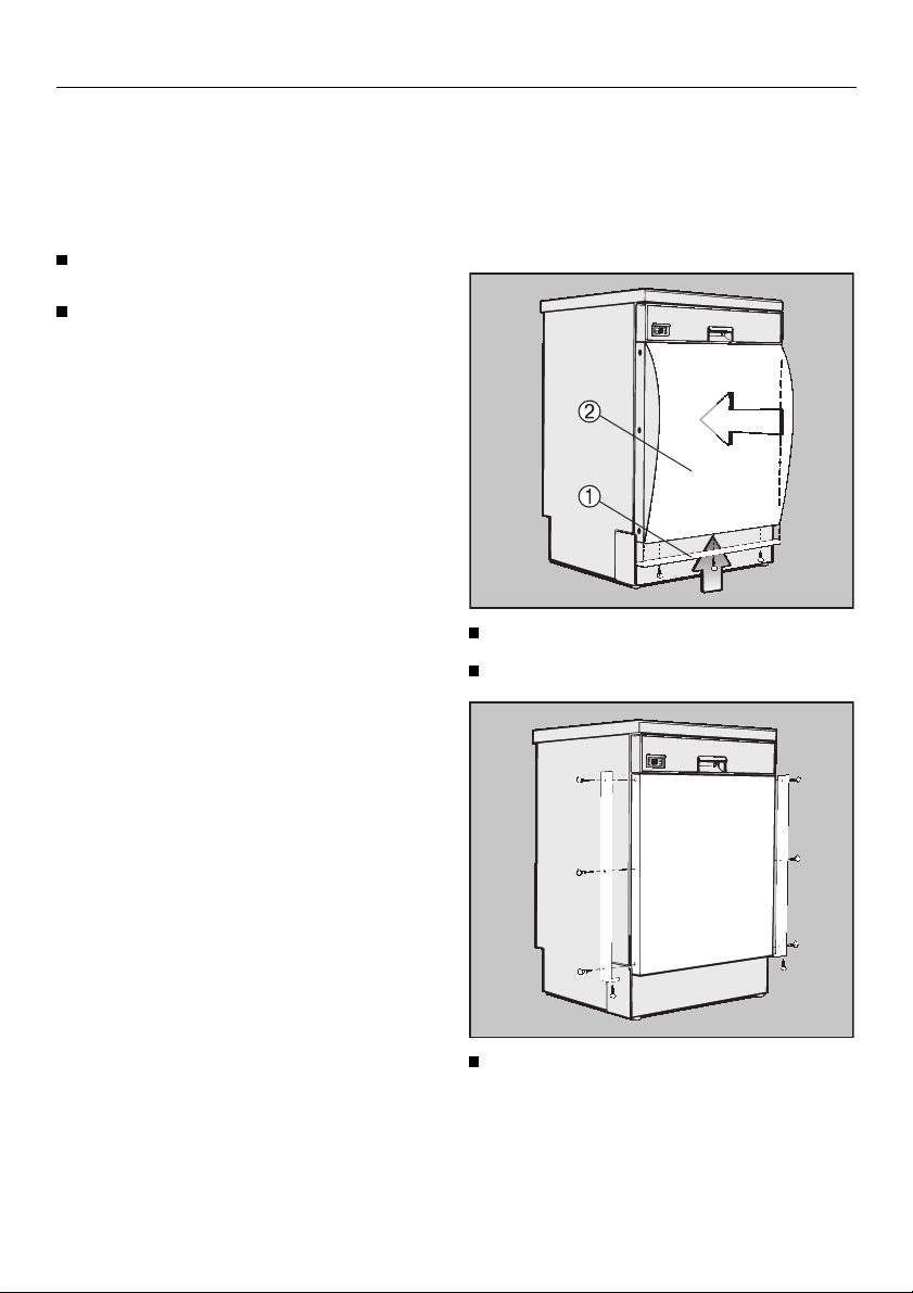
With decor panels 1 to 4 mm thick, an
extra decor frame adapter strip (special accessory) must be fitted to the
control facia panel.
Screw on the lower deco strip b .
Insert the decor panel c .
Dimensions for decor panels between 1
and 4 mm thick:
Models:
G 601 - G 624
G 801 - G 824
G 640 - G 691
G 840 - G 891
4
437 x 599 x 1 - 4 mm
}
587 x 599 x 1 - 4 mm
}
Screw the side decor strips into
position.

Installing integrated “i” Dishwashers
Installing integrated “i” Dishwashers
Integrated (“i”) dishwashers
“i” dishwashers are specially designed
for building under a continuous worktop.
– The control panel with its acces-
sories is included with the “i” dishwasher in a separate package for onsite fixing.
– The front is designed to be fitted with
a base unit “door” front to match the
kitchen furniture.
– The dishwasher does not have a
plinth facia. The plinth area can be
covered either with facia to match
your kitchen furniture if available, or
another facia. The separate plinth
facia can be fitted to match the
height of adjacent plinths. The plinth
return is freely adjustable.
All notes on installation are described
in the following section.
The “i” model dishwasheres can be
coverted into a built-under “U” dishwasher.
– A decor set GDU must be used.
– A plinth facia to cover the plinth area
is supplied with the decor set. The
plinth facia can be fitted to match
the height of adjacent plinths. The
plinth return is freely adjustable.
The decor set is supplied with a
separate installation booklet.
To ensure stability, “i” and “U”
model dishwashers must only be installed under a continuous worktop
which must be securely screwed to
neighbouring units.
The dishwasher must not be installed under a hob. The high
radiant temperatures which are
sometimes generated by a hob
could damage the dishwasher.
5
Installing integrated “i” Dishwashers
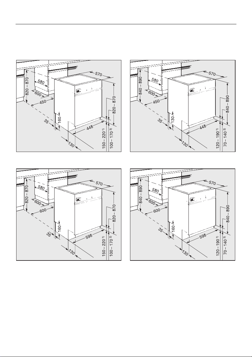
Building in dimensions
Dishwasher models G 601 - G 624
Dishwasher models G 640 - G 691
Dishwasher models G 801 - G 824
Dishwasher models G 840 - G 891
1) with 870 mm machine height
2) with 820 mm machine height
Range of adjustment approx. 5 cm (82 87 cm total height).
Extended machine feet are available at
extra cost, (special accessory) where a
machine height of 87 to 92 cm is required.
6
1) with 890 mm machine height
2) with 840 mm machine height
Range of adjustment approx. 5 cm (84 89 cm total height).
Extended machine feet are available at
extra cost, (special accessory) where a
machine height of 89 to 94 cm is required.
Installing integrated “i” Dishwashers
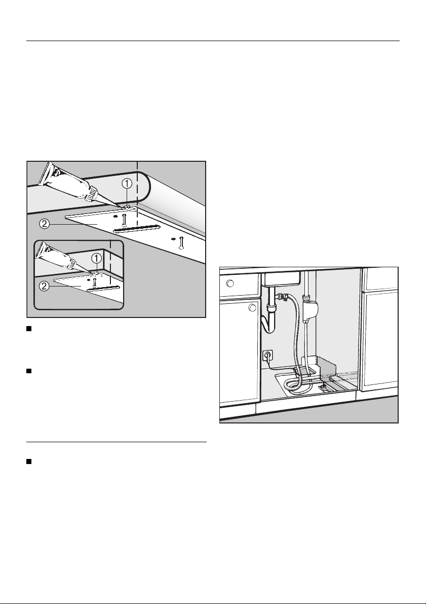
1.Fit worktop protection
A stainless steel “niro” cover plate is
supplied with the machine to protect
the underside of the worktop against
steam rising from the machine.
The cover plate is supplied as standard with “i” models.
Squeeze sealant from the tube supplied
b into the angle of the “niro”
plate.
2.Building the dishwasher
into a niche
Connection to water and drainage
should be sited beside and not behind
the dishwasher for accessibility. Connections are usually made in the area
under the sink. Many kitchen unit manufacturers provide a cutout in the base
of the sink base unit for the hoses to be
fed through.
If the base unit has no opening and if
there is not an opening through the
plinth area for connections, one must
be cut.
Suggested dimensions: 60 x 110 mm.
Align the “niro” plate c to the front
edge of the worktop - see illustration and then use the tacks supplied to
nail the “niro” plate to the underside
of the worktop.
Worktops with wood or laminate edging:
Nail the tacks through the holes
further back from the edge.
7
Installing integrated “i” Dishwashers
Slides
The slides make installation of the dishwasher easier and protect the floor
from possible damage when moving
the appliance into and out of the recess. They are also used for adjusting
the height of the rear screw feet.
Adjust the height manually before installing the dishwasher.
Leave a space of approx. 5 mm below
the worktop to allow the dishwasher
to be pushed back easily into the recess. Make sure that the dishwasher
stands level.
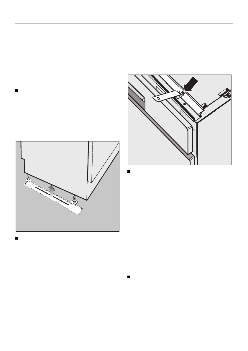
Press the slides - with the ratchet at
the rear - under the screw feet.
Securing pieces
To ensure stability, the dishwasher must
be fixed securely to the worktop (step 6).
Two securing pieces are supplied for
this purpose.
Fit the securing pieces into the slots
on both the left and right hand sides.
Granite and marble worktops:
With these worktops the dishwasher
must be securely screwed to neighbouring units on the right and left hand
sides. For this you will require two special fixing brackets (available as a special accessory at extra cost).
The angle support for the water drainage hose at the rear of the dishwasher
can be turned.
Turn the angle support in the direction of the on-site connection for the
drainage hose.
8
Installing integrated “i” Dishwashers
Push the dishwasher right back into
the recess. Ensure that the drain
hose, inlet hose and the electric
cable are laid to reach the connection point without any kinks.
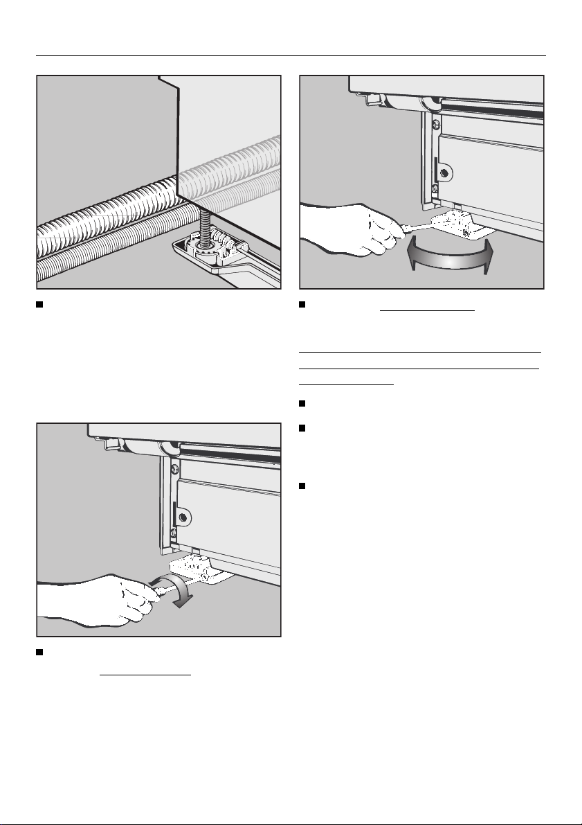
Screw feet
Use a TORX T20 screwdriver to adjust the
quired height.
rear screw feet to the re-
Adjust the front screw feet manually
or with a flat blade screwdriver.
It is easier to adjust the screw feet if the
weight of the dishwasher is not bearing
down on them.
If possible tip the machine slightly.
For fine adjustments it may be
necessary to press with a screwdriver against the cogs of the feet.
Screw the feet out until the dishwasher is right up against the underside of the worktop, to which it will
be screwed later. Ensure that the
dishwasher stands level.
Higher = turn clockwise
Lower = turn anti-clockwise
Several turns are needed to adjust 1 mm
in height.
9
 Loading...