

Page 1
881 Compact IC pro
881 Compact IC pro – Anion – MCS
Manual
8.881.8014EN
Page 2

Page 3

Metrohm AG
CH-9100 Herisau
Switzerland
Phone +41 71 353 85 85
Fax +41 71 353 89 01
info@metrohm.com
www.metrohm.com
881 Compact IC pro
881 Compact IC pro – Anion – MCS
2.881.0030
8.881.8014EN
Manual
05.2011 zst
Page 4

Teachware
Metrohm AG
CH-9100 Herisau
teachware@metrohm.com
This documentation is protected by copyright. All rights reserved.
Although all the information given in this documentation has been
checked with great care, errors cannot be entirely excluded. Should you
notice any mistakes please send us your comments using the address
given above.
Documentation in additional languages can be found on
http://products.metrohm.com under Literature/Technical documenta-
tion.
Page 5

■■■■■■■■■■■■■■■■■■■■■■
Table of contents
1 Introduction 1
1.1 Instrument description ......................................................... 1
1.2 Intended use ......................................................................... 3
1.3 About the documentation ................................................... 3
1.3.1 Symbols and conventions ........................................................ 3
1.4 Safety instructions ................................................................ 4
1.4.1 General notes on safety ........................................................... 4
1.4.2 Electrical safety ........................................................................ 4
1.4.3 Tubing and capillary connections ............................................. 5
1.4.4 Flammable solvents and chemicals ........................................... 5
1.4.5 Recycling and disposal ............................................................. 6
2 Overview of the instrument 7
2.1 Front ...................................................................................... 7
Table of contents
2.2 Rear ........................................................................................ 8
3 Installation 10
3.1 About this chapter .............................................................. 10
3.2 Initial installation ................................................................ 10
3.3 Installation diagram ........................................................... 14
3.4 Setting up the instrument .................................................. 17
3.4.1 Packaging .............................................................................. 17
3.4.2 Checks .................................................................................. 17
3.4.3 Location ................................................................................ 17
3.5 Capillary connections in the IC system ............................. 17
3.6 Rear of the instrument ....................................................... 20
3.6.1 Transport locking screws ....................................................... 20
3.6.2 Leak sensor ........................................................................... 20
3.6.3 Drainage tubings ................................................................... 21
3.7 Capillary and cable feed-throughs .................................... 23
3.8 Eluent ................................................................................... 25
3.8.1 Connecting eluent bottle ....................................................... 25
3.9 Eluent degasser ................................................................. 29
881 Compact IC pro – Anion – MCS
3.10 High pressure pump ........................................................... 31
3.10.1 Capillary connections high pressure pump/purge valve ........... 31
3.10.2 Deaerating the high pressure pump ....................................... 33
3.11 Inline filter ........................................................................... 35
■■■■■■■■
III
Page 6

Table of contents
■■■■■■■■■■■■■■■■■■■■■■
3.12 Pulsation absorber ............................................................. 36
3.13 Sample degasser ................................................................. 37
3.14 Injection valve ..................................................................... 39
3.14.1 Connecting the injection valve ............................................... 39
3.14.2 Mode of operation of the injection valve ............................... 40
3.14.3 Selecting the sample loop ...................................................... 41
3.15 Column heater .................................................................... 41
3.16 Peristaltic pump .................................................................. 45
3.16.1 Principle of the peristaltic pump ............................................. 45
3.16.2 Installing the peristaltic pump ................................................ 47
3.17 Metrohm Suppressor Module (MSM) ............................... 51
3.17.1 Connecting the suppressor .................................................... 51
3.18 Metrohm CO2 Suppressor (MCS) ....................................... 54
3.18.1 General information on the MCS ........................................... 54
3.18.2 Connecting MCS ................................................................... 54
3.18.3 Installing the adsorption cartridges ........................................ 56
3.19 Connecting the instrument ................................................ 58
3.19.1 Connecting the instrument to the PC ..................................... 58
3.19.2 Connecting the instrument to mains supply ........................... 58
3.20 Guard column ..................................................................... 59
3.21 Separation column ............................................................. 60
4 Start-up 63
4.1 Initial start-up ..................................................................... 63
4.2 Conditioning ........................................................................ 64
5 Operation and maintenance 66
5.1 General notes ...................................................................... 66
5.1.1 Care ...................................................................................... 66
5.1.2 Maintenance by Metrohm Service .......................................... 66
5.1.3 Operation .............................................................................. 67
5.1.4 Shutting down ...................................................................... 67
5.2 Capillary connections ......................................................... 67
5.2.1 Operation .............................................................................. 67
5.3 Door ..................................................................................... 68
5.4 Eluent ................................................................................... 68
5.4.1 Production ............................................................................. 68
5.4.2 Operation .............................................................................. 69
■■■■■■■■
IV
5.5 High pressure pump ........................................................... 69
5.5.1 Protection .............................................................................. 69
5.5.2 Maintenance ......................................................................... 70
881 Compact IC pro – Anion – MCS
Page 7

■■■■■■■■■■■■■■■■■■■■■■
Table of contents
5.6 Inline filter ........................................................................... 80
5.6.1 Maintenance ......................................................................... 80
5.7 Sample degasser ................................................................. 82
5.7.1 Operation .............................................................................. 82
5.8 Inline sample preparation .................................................. 82
5.9 Rinsing the sample path .................................................... 83
5.10 Injection valve .................................................................... 84
5.10.1 Protection .............................................................................. 84
5.11 Peristaltic pump .................................................................. 84
5.11.1 Operation .............................................................................. 84
5.11.2 Maintenance ......................................................................... 85
5.12 Metrohm Suppressor Module (MSM) ............................... 87
5.12.1 Protection .............................................................................. 87
5.12.2 Operation Suppressor ........................................................... 87
5.12.3 Maintenance ......................................................................... 88
5.13 Metrohm CO2 Suppressor (MCS) ....................................... 93
5.13.1 Replacing the CO2 adsorption cartridge ................................. 93
5.13.2 Regenerating the H2O adsorption cartridge ............................ 93
5.14 Separation column ............................................................. 94
5.14.1 Separating efficiency .............................................................. 94
5.14.2 Protection .............................................................................. 94
5.14.3 Storage ................................................................................. 95
5.14.4 Regeneration ......................................................................... 95
5.15 Quality Management and validation with Metrohm ....... 95
6 Troubleshooting 97
6.1 Problems and their solutions ............................................. 97
7 Technical specifications 101
7.1 Reference conditions ........................................................ 101
7.2 Instrument ......................................................................... 101
7.3 Leak sensor ....................................................................... 101
7.4 Ambient conditions .......................................................... 101
7.5 Housing ............................................................................. 102
7.6 Eluent degasser ................................................................ 102
7.7 High pressure pump ......................................................... 102
881 Compact IC pro – Anion – MCS
7.8 Sample degasser ............................................................... 103
7.9 Injection valve ................................................................... 103
7.10 Column heater .................................................................. 104
7.11 Peristaltic pump ................................................................ 104
■■■■■■■■
V
Page 8

Table of contents
■■■■■■■■■■■■■■■■■■■■■■
7.12 Metrohm Suppressor Module (MSM) ............................. 104
7.13 Metrohm CO2 Suppressor (MCS) ..................................... 105
7.14 Mains connection ............................................................. 105
7.15 Interfaces .......................................................................... 105
7.16 Safety specification .......................................................... 106
7.17 Electromagnetic compatibility (EMC) ............................. 106
7.18 Weight ............................................................................... 107
8 Conformity and warranty 108
8.1 Declaration of Conformity ............................................... 108
8.2 Quality Management Principles ...................................... 109
8.3 Warranty (guarantee) ....................................................... 110
9 Accessories 112
9.1 Scope of delivery .............................................................. 112
9.2 Optional accessories ........................................................ 122
Index 125
■■■■■■■■
VI
881 Compact IC pro – Anion – MCS
Page 9

■■■■■■■■■■■■■■■■■■■■■■
Table of figures
Figure 1 Front 881 Compact IC pro – Anion – MCS ......................................... 7
Figure 2 Rear 881 Compact IC pro – Anion – MCS .......................................... 8
Figure 3 Installation diagram 881 Compact IC pro – Anion – MCS ................. 15
Figure 4 Connection of capillaries with pressure screws ................................ 18
Figure 5 Connection for the leak sensor on the rear of the instrument .......... 21
Figure 6 Drainage tubings ............................................................................. 22
Figure 7 Capillary and cable feed-throughs ................................................... 24
Figure 8 Installing eluent bottle attachment .................................................. 26
Figure 9 Mounting aspiration filter ................................................................ 26
Figure 10 Install tubing weighting and aspiration filter .................................... 27
Figure 11 Eluent aspiration tubing fully equipped. ........................................... 27
Figure 12 Eluent bottle – connected ............................................................... 28
Figure 13 Eluent degasser ............................................................................... 30
Figure 14 Capillary connections high pressure pump/purge valve .................... 31
Figure 15 High pressure pump – Connect inlet ................................................ 32
Figure 16 Deaerate the high pressure pump .................................................... 34
Figure 17 Connecting the inline filter .............................................................. 36
Figure 18 Pulsation absorber – Connection ..................................................... 37
Figure 19 Sample degasser ............................................................................. 38
Figure 20 Injection valve – connected ............................................................. 39
Figure 21 Injection valve – Positions ................................................................ 40
Figure 22 Column heater ................................................................................ 42
Figure 23 Column heater – Installing capillaries ............................................... 44
Figure 24 Peristaltic pump ............................................................................... 46
Figure 25 Installing the pump tubing .............................................................. 47
Figure 26 Install pump tubing connection with filter ....................................... 48
Figure 27 Install pump tubing connection without filter .................................. 49
Figure 28 Suppressor – connection capillaries ................................................. 52
Figure 29 MCS – connection ........................................................................... 55
Figure 30 Adsorption cartridge holder ............................................................. 56
Figure 31 Pump head – removing the piston ................................................... 71
Figure 32 Components of the piston cartridge ................................................ 72
Figure 33 Tool for piston seal .......................................................................... 73
Figure 34 Removing the piston seal ................................................................. 74
Figure 35 Inserting the piston seal into the tool ............................................... 74
Figure 36 Inserting the piston seal into the pump head ................................... 75
Figure 37 Removing valves .............................................................................. 76
Figure 38 Dismantling valve ............................................................................ 77
Figure 39 Components of the inlet valve and outlet valve ................................ 78
Figure 40 Change filters (of the inline filter) ..................................................... 80
Figure 41 Pump tubing connection – Changing the filter ................................. 86
Figure 42 Parts of the suppressor .................................................................... 88
Table of figures
881 Compact IC pro – Anion – MCS
■■■■■■■■
VII
Page 10

Page 11

■■■■■■■■■■■■■■■■■■■■■■
1 Introduction
1.1 Instrument description
The instrument 881 Compact IC pro – Anion – MCS is one of the
model versions of the 881 Compact IC pro line of instruments manufactured by the Metrohm Company. The 881 Compact IC pro line of instruments is distinguished by:
■ the intelligence of its components, which are able to monitor and
optimize all functions and to provide documentation according to FDA
requirements.
■ its compact style of construction.
■ its transparency. All components are easily accessible and arranged in
a clear manner.
■ its safety. Chemicals and electronics are separated and a leak sensor is
integrated in the wet end.
■ its environmental compatibility.
■ its low noise emission.
1 Introduction
The instrument is operated with MagIC Net™ software. It is connected
via a USB connection to a PC on which MagIC Net™ is installed. The software automatically recognizes the instrument and checks its functional
readiness. MagIC Net™ controls and monitors the instrument, evaluates
the measured data and administers it in a database. The operation of
MagIC Net is described in the online help or in the tutorial for
MagIC Net™.
The instrument contains the following components:
Eluent degasser
The eluent degasser removes gas bubbles and dissolved gases from the
eluent. For degassing, the eluent flows into a vacuum chamber through a
special fluoropolymer capillary.
High pressure pump
The intelligent and low pulsation high pressure pump pumps the eluent
through the system. It is equipped with a chip on which its technical specifications and "life history" (operating hours, service data, … ) are saved.
Inline filter
Inline filters protect the separation column securely against possible contamination from the eluent. Inline filters can however also just as well be
used for the purpose of protecting other sensitive components against
contaminations in the solutions used. The filter platelets with a pore size
881 Compact IC pro – Anion – MCS
■■■■■■■■
1
Page 12

1.1 Instrument description
■■■■■■■■■■■■■■■■■■■■■■
of 2 µm can be replaced quickly and easily. They remove particles like e. g.
bacteria and algae from the solutions.
Pulsation absorber
The pulsation absorber protects the separation column from damage
caused by pressure fluctuations when switching the injection valve, and
reduces interfering pulsations during highly sensitive measurements.
Sample degasser
The sample degasser removes gas bubbles and dissolved gases from the
sample. For degassing, the sample flows into a vacuum chamber through
a special fluoropolymer capillary.
Injection valve
The injection valve connects the eluent and sample path through rapid
and precise valve switchover. A precisely measured amount of sample
solution is injected and rinsed with eluent onto the separation column.
Column heater
The perfect isolation of the column chamber ensures thermally stable conditions for the separation column. The temperature of the column heater
can be set in the software.
Peristaltic pump
The Peristaltic pump is used for pumping sample and auxiliary solutions. It
can rotate in both directions.
Metrohm Suppressor Module (MSM)
The MSM is used for chemical suppression in anion analysis with conductivity detection or UV detection.It is pressure-stable, robust and resistant
to solvents.
Metrohm CO2 Suppressor (MCS)
The Metrohm CO2 Suppressor (MCS) removes the CO2 from the eluent
flow. This reduces the background conductivity, improves the detection
sensitivity and minimizes the injection and carbonate peaks.
Separation column
The intelligent separation column is the heart of the ion chromatographic
analysis. It separates the different components corresponding to their
interactions with the column. Metrohm separation columns are equipped
with a chip on which their technical specifications and their history (first
use / setting up, operating hours, injections, …) are saved.
■■■■■■■■
2
881 Compact IC pro – Anion – MCS
Page 13
■■■■■■■■■■■■■■■■■■■■■■
1.2 Intended use
The instrument 881 Compact IC pro – Anion – MCS is used for ion
chromatographic determination of anions or polar substances with
sequential suppression:
■ Chemical suppression with the Metrohm Suppressor Module (MSM)
and subsequent
■ CO
2
The use of sequential suppression reduces background conductivity to a
minimum.
If required, the instrument can also be used for the determination of cations or anions without suppression.
This instrument is suitable for processing chemicals and flammable samples. The usage of the 881 Compact IC pro – Anion – MCS therefore
requires that the user has basic knowledge and experience in the handling
of toxic and caustic substances. Knowledge with respect to the application of the fire prevention measures prescribed for laboratories is also
mandatory.
1 Introduction
suppression with the Metrohm CO2 Suppressor (MCS).
1.3 About the documentation
1.3.1 Symbols and conventions
The following symbols and styles are used in this documentation:
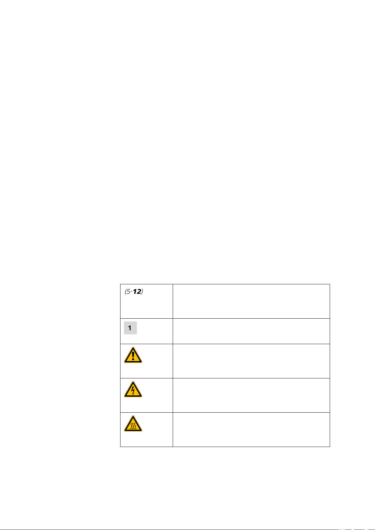
Cross-reference to figure legend
The first number refers to the figure number, the
second to the instrument part in the figure.
Instruction step
Carry out these steps in the sequence shown.
Warning
This symbol draws attention to a possible life hazard
or risk of injury.
Warning
This symbol draws attention to a possible hazard due
to electrical current.
Warning
881 Compact IC pro – Anion – MCS
This symbol draws attention to a possible hazard due
to heat or hot instrument parts.
■■■■■■■■
3
Page 14
1.4 Safety instructions
1.4 Safety instructions
1.4.1 General notes on safety
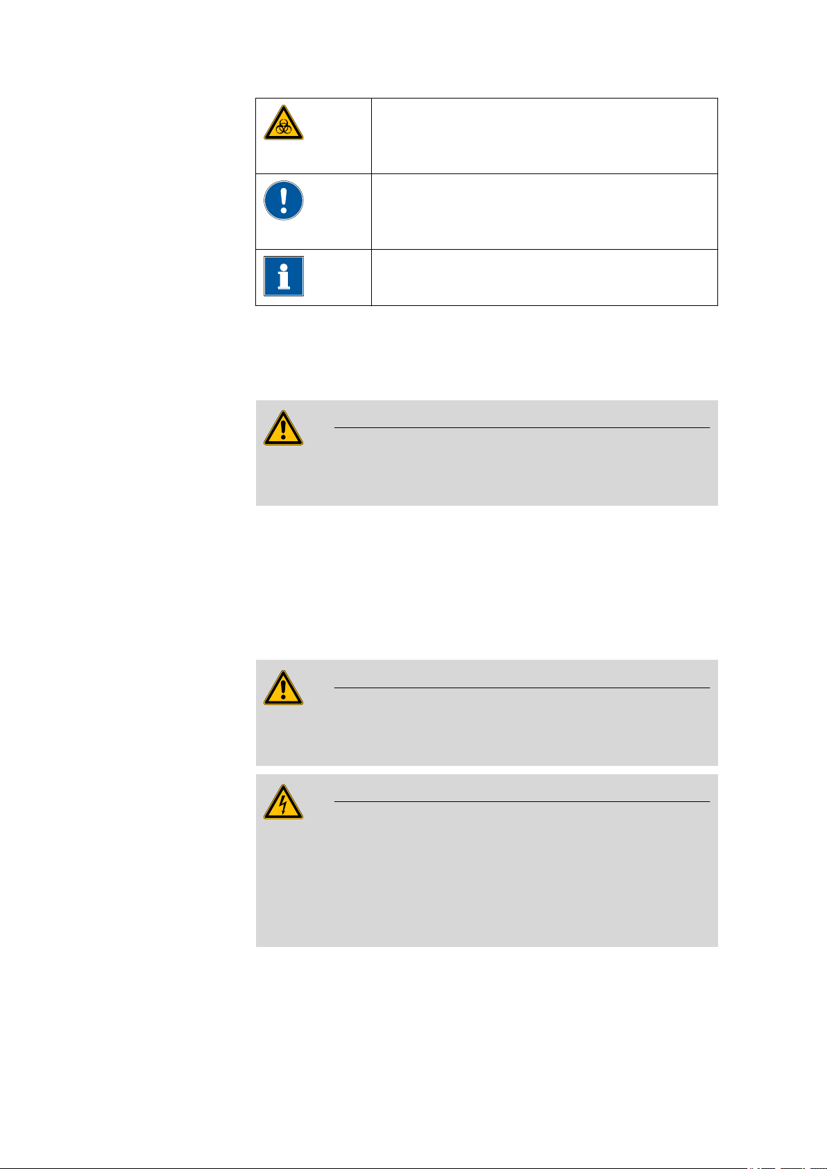
Warning
This instrument may only be operated in accordance with the specifications in this documentation.
■■■■■■■■■■■■■■■■■■■■■■
Warning
This symbol draws attention to a possible biological
hazard.
Caution
This symbol draws attention to a possible damage of
instruments or instrument parts.
Note
This symbol marks additional information and tips.
This instrument has left the factory in a flawless state in terms of technical
safety. To maintain this state and ensure non-hazardous operation of the
instrument, the following instructions must be observed carefully.
1.4.2 Electrical safety
The electrical safety when working with the instrument is ensured as part
of the international standard IEC 61010.
Only personnel qualified by Metrohm are authorized to carry out service
work on electronic components.
Never open the housing of the instrument. The instrument could be
damaged by this. There is also a risk of serious injury if live components
are touched.
There are no parts inside the housing which can be serviced or replaced
by the user.
Warning
Warning
■■■■■■■■
4
881 Compact IC pro – Anion – MCS
Page 15
■■■■■■■■■■■■■■■■■■■■■■
1 Introduction
Mains voltage
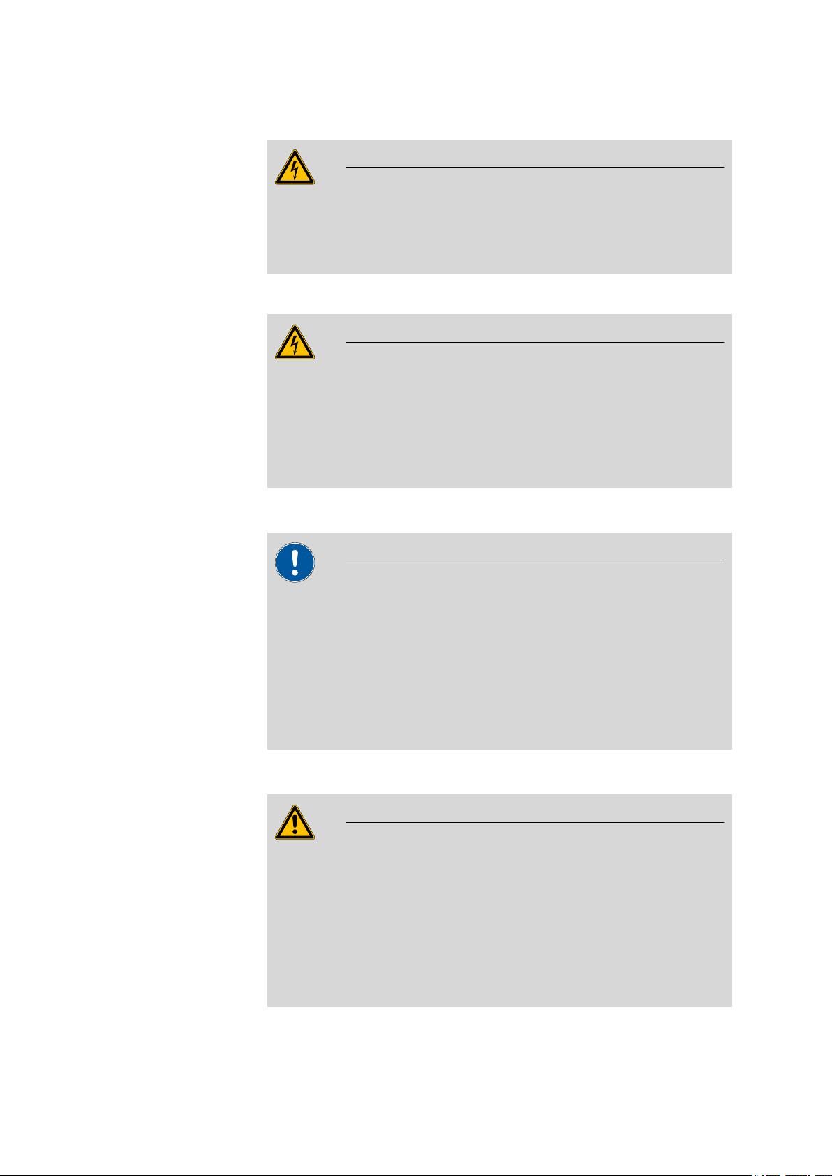
Warning
An incorrect mains voltage can damage the instrument.
Only operate this instrument with a mains voltage specified for it (see
rear panel of the instrument).
Protection against electrostatic charges
Warning
Electronic components are sensitive to electrostatic charges and can be
destroyed by discharges.
Always pull the mains cable out of the mains connection socket before
connecting or disconnecting electrical appliances on the rear panel of
the instrument.
1.4.3 Tubing and capillary connections
Caution
Leaks in tubing and capillary connections are a safety risk. Tighten all
connections well by hand. Avoid applying excessive force to tubing
connections. Damaged tubing ends lead to leakage. Appropriate tools
can be used to loosen connections.
Check the connections regularly for leakage. If the instrument is used
mainly in unattended operation, then weekly inspections are mandatory.
1.4.4 Flammable solvents and chemicals
Warning
All relevant safety measures are to be observed when working with
flammable solvents and chemicals.
■ Set up the instrument in a well-ventilated location (e.g. laboratory
flue).
■ Keep all sources of flame far from the workplace.
■ Clean up spilled fluids and solids immediately.
■ Follow the safety instructions of the chemical manufacturer.
881 Compact IC pro – Anion – MCS
■■■■■■■■
5
Page 16

1.4 Safety instructions
1.4.5 Recycling and disposal
This product is covered by European Directive 2002/96/EC, WEEE – Waste
from Electrical and Electronic Equipment.
The correct disposal of your old equipment will help to prevent negative
effects on the environment and public health.
More details about the disposal of your old equipment can be obtained
from your local authorities, from waste disposal companies or from your
local dealer.
■■■■■■■■■■■■■■■■■■■■■■
■■■■■■■■
6
881 Compact IC pro – Anion – MCS
Page 17
■■■■■■■■■■■■■■■■■■■■■■
1
12
10
2
3
4
7
5 6
8
13
11
9
2 Overview of the instrument
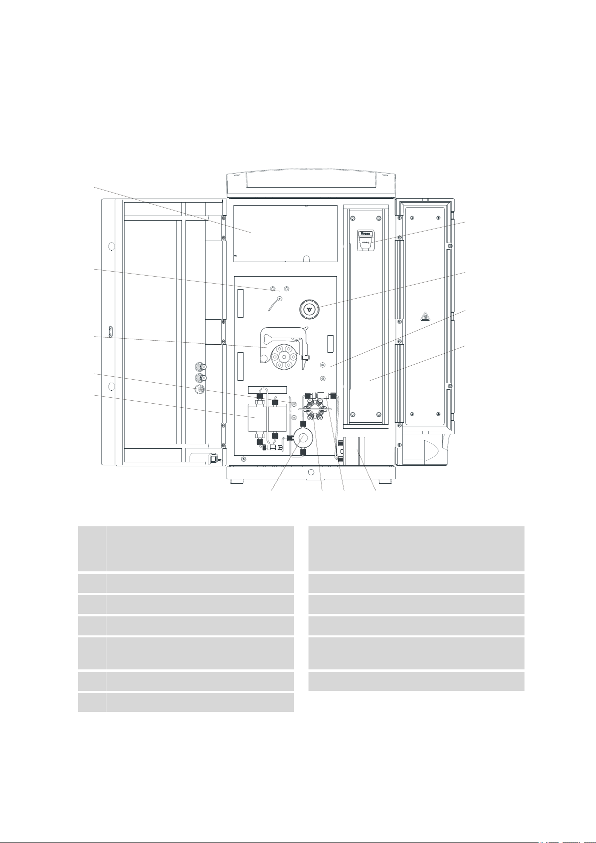
2.1 Front
2 Overview of the instrument
Figure 1 Front 881 Compact IC pro – Anion – MCS
Detector chamber
1
Room for the detector and the adsorption
cartridges for the MCS.
High pressure pump
3
Inline filter
5
Injection valve
7
Column holder
9
With column recognition.
Metrohm Suppressor Module (MSM)
11
Sample degasser
13
881 Compact IC pro – Anion – MCS
Eluent degasser
2
Purge valve
4
Pulsation absorber
6
Column heater
8
Peristaltic pump
10
Metrohm CO2 Suppressor (MCS)
12
■■■■■■■■
7
Page 18
2.2 Rear
14
15
16
17
18
20
21
19
22
11
1213
1
2
4
5
3
7
8
10
9
6
2.2 Rear
■■■■■■■■■■■■■■■■■■■■■■
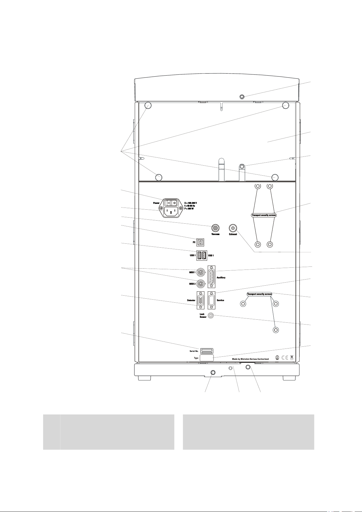
Figure 2 Rear 881 Compact IC pro – Anion – MCS
1
■■■■■■■■
8
Drainage tubing connector
For connecting the drainage tubing which
leads away escaped fluids from the flask
holder.
Rear panel
2
Removable. Access to the detector chamber.
881 Compact IC pro – Anion – MCS
Page 19

■■■■■■■■■■■■■■■■■■■■■■
2 Overview of the instrument
Drainage tubing connector
3
For connecting the drainage tubing which
leads away escaped fluids from the detector
chamber.
Exhaust air opening
5
For extracting the air from the vacuum
chamber. Labeled with Exhaust.
Service connection socket
7
For Metrohm service only.
Leak sensor connection socket
9
For connecting the leak sensor connection
cable.
Drainage tubing connector
11
For connecting the drainage tubing which
leads escaped fluids to the leak sensor.
Drainage tubing connector
13
For connecting the drainage tubing which
leads escaped fluids to the waste vessel.
Transport locking screws
4
For securing the vacuum pump when transporting the instrument.
Auxiliary connection socket
6
For connecting a 891 Professional Analog
out (2.891.0010).
Transport locking screws
8
For securing the high pressure pump when
transporting the instrument.
Type plate
10
Leak sensor connection cable
12
Extractable. For connecting the leak sensor.
Serial number
14
Detector connection socket
15
For connecting Metrohm detectors. Labeled
with Detector.
USB connectors
17
2 USB connectors labeled with USB 1 and
USB 2.
Vacuum connection
19
Plugged with a stopper. Not Used.
Mains switch
21
For switching the instrument on and off.
I = On
O = Off
MSB connectors
16
2 MSB connectors for connecting MSB devices. Labeled with MSB 1 and MSB 2.
MSB = Metrohm Serial Bus
PC connection socket
18
For connecting the instrument to the computer with the USB cable (6.2151.020).
Mains connection socket
20
For connecting the mains cable.
Knurled screws
22
For fastening the removable rear panel.
881 Compact IC pro – Anion – MCS
■■■■■■■■
9
Page 20

3.1 About this chapter
3 Installation
3.1 About this chapter
The Installation chapter contains
■ this overview.
■ a brief set of instructions for the initial installation of the 881 Compact
IC pro – Anion – MCS. At each step you will find cross-references to
more detailed installation instructions for individual components,
should you require such aids.
■ an installation diagram (see Chapter 3.3, page 14), showing a com-
pletely installed 881 Compact IC pro – Anion – MCS.
■ several chapters with detailed installation instructions for all compo-
nents, including those that are already installed at the time the instrument is delivered.
■■■■■■■■■■■■■■■■■■■■■■
3.2 Initial installation
Note
A number of the capillaries is already connected at the time the instrument is delivered.
The following work steps must still be carried out:
881 Compact IC proInstalling – Anion – MCS
1
Setting up the instrument
(see Chapter 3.4, page 17).
2
Installations on the rear of the instrument
■ Place the detector in the instrument and connect it (see manual
of the detector).
■ Remove all of the transport locking screws with the 4 mm hexa-
gon key (6.2621.030) and keep them in a safe place.
■ Connect the leak sensor (see Chapter 3.6.2, page 20).
■ Connect the drainage tubings (see Chapter 3.6.3, page 21).
■■■■■■■■
10
881 Compact IC pro – Anion – MCS
Page 21

■■■■■■■■■■■■■■■■■■■■■■
3
Connecting the eluent path
■ Lead the eluent aspiration tubing (6.1834.080) out of the instru-
ment through a capillary feed-through and connect it with the
eluent bottle (see Chapter 3.8.1, page 25).
■ Connect the column inlet capillary (6.1831.100) and the capillary
of the MSM labeled with in to one another with a coupling
(6.2744.040) and two short pressure screws (6.2744.070).
■ Use a long pressure screw (6.2744.090) to connect the capillary
of the MSM labeled with out to the input of the of the MCS (see
"Connecting the MCS", page 55).
■ Connect the detector inlet capillary with a long pressure screw
(6.2744.090) to the output of the MCS (see "Connecting the
MCS", page 55).
4
Connecting the sample path
Note
3 Installation
The sample degasser does not have to be connected. We recommend the usage of the sample degasser only if the sample matrix
requires it (see Chapter 3.13, page 37).
■ Guide the sample aspiration capillary connected to the sample
input of the injection valve out of the instrument through a capillary feed-through and connect it with the Sample Processor, if
applicable (see Sample Processor manual)..
■ Guide the sample outlet capillary connected to the sample output
of the injection valve out of the instrument through a capillary
feed-through and onward to the waste container and then fasten
it there.
5
Installing the peristaltic pump
(see Chapter 3.16.2, page 47)
Prepare the pump tubing for the regeneration solution:
■ Plug a tubing olive (6.2744.034) onto one end of the pump tub-
ing (6.1826.320).
Plug a pump tubing connection (6.2744.180) onto the other end
of the pump tubing.
881 Compact IC pro – Anion – MCS
■■■■■■■■
11
Page 22

3.2 Initial installation
■■■■■■■■■■■■■■■■■■■■■■
■ Connect one end of the aspirating capillary (6.1803.020) for the
regeneration solution to the tubing olive on the pump tubing
using a short pressure screw (6.2744.070).
Guide the other end of the aspirating capillary out of the instrument through a capillary feed-through, slide it through a bottle
attachment (6.1602.150) and screw the bottle attachment onto
the bottle (6.1608.020) containing the regeneration solution.
Ensure that the end of the aspirating capillary reaches down to
the bottom of the bottle.
■ Place the pump tubing into a tubing cartridge.
Prepare a second pump tubing for the rinsing solution:
■ Plug a tubing olive (6.2744.034) onto one end of the pump tub-
ing (6.1826.320).
Plug a pump tubing connection (6.2744.180) onto the other end
of the pump tubing.
■ Connect one end of the aspirating capillary (6.1803.020) for the
rinsing solution to the tubing olive on the pump tubing using a
short pressure screw (6.2744.070).
Guide the other end of the aspirating capillary out of the instrument through a capillary feed-through, slide it through a bottle
attachment (6.1602.150) and screw the bottle attachment onto
the bottle (6.1608.020) containing the rinsing solution. Ensure
that the end of the aspirating capillary reaches down to the bottom of the bottle.
■ Place the pump tubing into a tubing cartridge.
Place both tubing cartridges into the peristaltic pump.
6
Connecting the MSM
(see Chapter 3.17, page 51)
■ Connect the capillary of the MSM labeled with regenerant to the
pump tubing connection of the pump tubing for the regeneration
solution using a short pressure screw (6.2744.070).
■ Connect the capillary of the MSM labeled with rinsing solution
to the pump tubing connection of the pump tubing for the rinsing
solution using a short pressure screw (6.2744.070).
■ Guide the two capillaries of the MSM labeled with waste reg.
and waste rins. out of the instrument through a capillary feed
through to a waste container and fasten them there.
7
Connecting the MCS
(see Chapter 3.18, page 54)
■■■■■■■■
12
881 Compact IC pro – Anion – MCS
Page 23

■■■■■■■■■■■■■■■■■■■■■■
3 Installation
■ Attach the CO
adsorption cartridge (6.2837.000) to the adsorp-
2
tion cartridge holder (6.2057.080) (see "Installing the adsorption
cartridges", page 57).
■ Prepare the H
O adsorption cartridge (6.2837.010) (see leaflet to
2
the H2O adsorption cartridge) and attach it to the adsorption cartridge holder as well (see Figure 30, page 56).
■ Plug the adapter (6.1808.190) onto the PVC tubing and connect
the two adsorption cartridges with one another (see Figure 30,
page 56).
■ Place the adsorption cartridge (6.2057.080) holder in the detector
chamber.
■ Connect the MCS air aspirating capillary (3-15) to the tip of the
CO2 adsorption cartridge (6.2837.000).
8
Connecting the instrument
■ Connect the instrument to a computer (see Chapter 3.19.1, page
58) on which the software MagIC Net™ is installed using the
USB cable (6.2151.020).
■ Connect the instrument to the mains supply (see Chapter 3.19.2,
page 58).
9
Initial start-up
(see Chapter 4.1, page 63)
■ Switch on the PC and start MagIC Net™.
■ Switch on the instrument.
■ Deaerate the high pressure pump (see Chapter 3.10.2, page
33).
■ Set contact pressure of the peristaltic pump (see "Set flow rate",
page 50).
■ Rinse the instrument without column with eluent for 5 minutes.
10
Installing guard and separation column
■ Remove the coupling (6.2744.040) between the column inlet
capillary and the capillary of the MSM labeled with in.
■ (Optional) Connect guard column (see Chapter 3.20, page 59)
– Fasten the guard column to the end of the column inlet
capillary (see leaflet to the guard column).
– Rinse the guard column with eluent for approx. 5 minutes.
881 Compact IC pro – Anion – MCS
■■■■■■■■
13
Page 24

3.3 Installation diagram
■■■■■■■■■■■■■■■■■■■■■■
■ Connect the separation column (see Chapter 3.21, page 60)
– Connect the inlet oft the separation column either with the
end of the column input capillary using a PEEK pressures
screw (6.2744.070).
or
Connect the inlet of the separation column with the guard
column (if used) (see leaflet to the separation column)
– Connect the MSM capillary labeled with in with the output
of the separation column using a PEEK pressure screw
(6.2744.070).
■ Hang separation column with chip in the column holder of the
instrument.
11
Conditioning the instrument
(see Chapter 4.2, page 64)
The instrument is now ready for measuring samples.
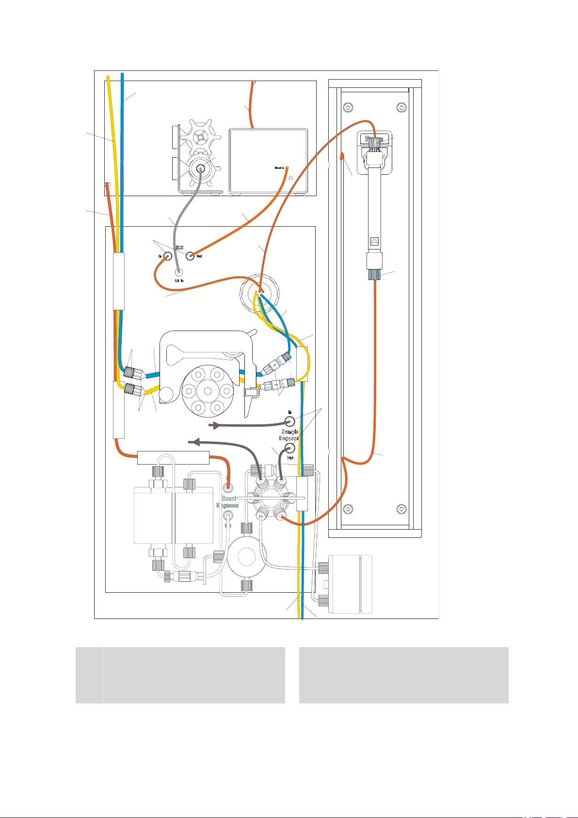
3.3 Installation diagram
The following installation diagram shows the schematics of the front of
the instrument after installation has been completed with the connected
sample degasser. Many capillaries are already installed at the time the
instrument is delivered; these capillaries are not numbered in the diagram.
Numbered capillaries must be connected at the time of installation.
■■■■■■■■
14
881 Compact IC pro – Anion – MCS
Page 25
■■■■■■■■■■■■■■■■■■■■■■
1
2
6
19
19
16
18
7
8
9
10
11
12
13
14
3
4
19
20
21
19
17
5
15
22
22
23
2
3 Installation
Figure 3 Installation diagram 881 Compact IC pro – Anion – MCS
1
Eluent aspirating capillary (6.1834.080)
Connected to the eluent degasser.
Column input capillary (6.1831.150)
2
Connected to the injection valve and threaded into the capillary recesses of the column
heater.
881 Compact IC pro – Anion – MCS
■■■■■■■■
15
Page 26

3.3 Installation diagram
■■■■■■■■■■■■■■■■■■■■■■
MSM eluent inlet capillary
3
Labeled with in.
Detector inlet capillary
5
Regeneration solution aspirating capil-
7
lary (6.1803.020)
MSM regeneration solution inlet capil-
9
lary
Labeled with regenerant.
Rinsing solution aspirating capillary
11
(6.1803.020)
MSM rinsing solution inlet capillary
13
Labeled with rinsing solution.
MCS aspirating capillary
15
For aspirating air low in CO2 out of the CO
cartridge.
MSM eluent outlet capillary
4
Labeled with out.
Detector outlet capillary
6
Pump tubing (6.1826.320)
8
With orange/yellow stoppers, for the regeneration solution.
MSM regeneration solution outlet
10
capillary
Labeled with waste reg..
Pump tubing (6.1826.320)
12
With orange/yellow stoppers, for the rinsing
solution.
MSM rinsing solution outlet capillary
14
Labeled with waste rins..
Sample aspirating capillary
16
2
(6.1803.040)
Connection Sample Degasser – Sample Processor.
Sample aspirating capillary
17
(6.1803.040)
Connected to the injection valve. Can be
connected to the sample degasser if the
sample matrix requires it.
PEEK pressure screws, short
19
(6.2744.070)
Pump tubing connection (6.2744.180)
21
With safety device and filter, for connecting
capillaries to the outlet side of the peristaltic
pump.
Luer coupling (6.2744.120)
23
Mounted on the MCS aspirating capillary
with a short pressure screw (6.2744.070).
For connecting the CO2 adsorption cartridge.
Sample outlet capillary (6.1803.040)
18
Tubing olive (6.2744.034)
20
For connecting capillaries to the aspiration
side of the peristaltic pump.
PEEK pressure screws, long
22
(6.2744.090)
■■■■■■■■
16
881 Compact IC pro – Anion – MCS
Page 27

■■■■■■■■■■■■■■■■■■■■■■
3.4 Setting up the instrument
3.4.1 Packaging
The instrument is supplied in highly protective special packaging together
with the separately packed accessories. Keep this packaging, as only this
ensures safe transportation of the instrument.
3.4.2 Checks
Immediately after receipt, check whether the shipment has arrived complete and without damage by comparing it with the delivery note.
3.4.3 Location
The instrument has been developed for operation indoors and may not be
used in explosive environments.
Place the instrument in a location of the laboratory which is suitable for
operation, free of vibrations, protected from corrosive atmosphere, and
contamination by chemicals.
3 Installation
The instrument should be protected against excessive temperature fluctuations and direct sunlight.
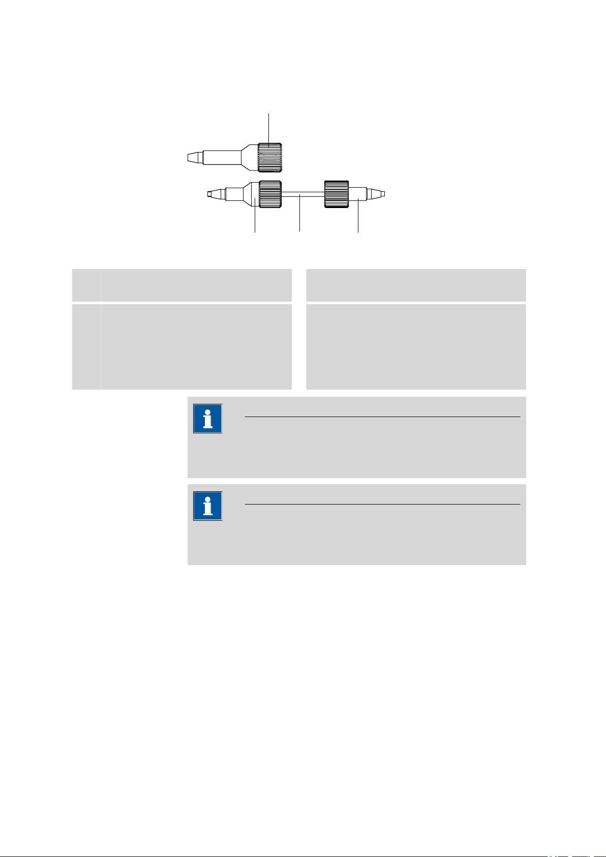
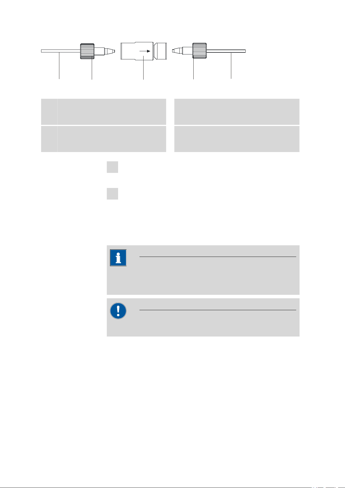
3.5 Capillary connections in the IC system
This chapter contains general information concerning the capillary connections in the IC instruments and systems.
Generally speaking, capillary connections between two components of an
IC system are made up of one connection capillary and two pressure
screws with which the capillary is connected to the respective components.
881 Compact IC pro – Anion – MCS
■■■■■■■■
17
Page 28
3.5 Capillary connections in the IC system
4
1
2 3
Pressure screws
Figure 4 Connection of capillaries with pressure screws
■■■■■■■■■■■■■■■■■■■■■■
PEEK pressure screw (6.2744.014)
1
Use on the injection valve.
PEEK pressure screw, short
3
(6.2744.070)
For use on the high pressure pump, the
purge valve, the inline filter, the pulsation
absorber, the guard column and the separation column.
In order to keep the dead volume as low as possible, capillary connections should generally be as short as possible.
For an improved overview, capillary and tubing connections can be
bundled with the 6.1815.010 spiral band.
Note
Note
Connection capillary
2
PEEK pressure screw, long
4
(6.2744.090)
Use on special components. Is not used on
all instruments.
PEEK capillaries (polyetheretherketone)
■■■■■■■■
18
Connection capillaries
PEEK capillaries and PTFE capillaries are used in the IC system.
PEEK capillaries are temperature-resistant up to 100°C, stable under pressure up to 400 bar, flexible, chemically inert and exhibit an extremely
smooth surface. They can be readily cut down to the desired length with
the 6.2621.080 capillary cutter.
Usage:
■ PEEK capillaries (6.1831.010) with an internal diameter of 0.25 mm for
the entire high pressure range.
881 Compact IC pro – Anion – MCS
Page 29

■■■■■■■■■■■■■■■■■■■■■■
3 Installation
■ PEEK capillaries (6.1831.030) with an internal diameter of 0.75 mm for
sample handling in the ultra trace range.
Caution
For the capillary connections between the injection valve and detector ,
PEEK capillaries with an internal diameter of 0.25 mm must be used.
These are already connected to a newly delivered instrument.
PTFE capillaries (polytetrafluoroethylene)
PTFE capillaries are transparent and enable visual tracing of the liquids to
be pumped. They are chemically inert, flexible and temperature-resistant
up to 80°C.
Usage:
PTFE capillaries (6.1803.0x0) are used for the low pressure range.
■ PTFE capillaries with internal diameter of 0.5 mm for sample handling.
■ PTFE capillaries with internal diameter of 0.97 mm for sample handling
as well as for rinsing solutions (they do not have to be in the scope of
delivery of the instrument).
Capillary connections
In order to achieve optimum analysis results, capillary connections in an IC
system must be absolutely tight and free of dead volume. Dead volume
occurs if two capillary ends connected to each other do not fit exactly,
thus allowing liquid to escape. There are two possible reasons for this:
■ The capillaries do not have exactly cut edges.
■ The two capillary ends do not completely meet.
One prerequisite for dead volume free capillary connection is, that both
capillary ends are cut exactly plane. Therefore we recommend only to cut
PEEK capillaries with the capillary cutter (6.2621.080).
881 Compact IC pro – Anion – MCS
Creating dead volume free capillary connections
To create dead volume free capillary connections, proceed as follows:
Slide the pressure screw over the capillary. Ensure that the capillary
1
protrudes 1–2 mm from the tip of the pressure screw.
Plug the capillary all the way into the connection or coupling until
2
the stop.
Only then start turning the pressure screw, while keeping the capil-
3
lary pressed in space.
■■■■■■■■
19
Page 30

3.6 Rear of the instrument
Colored sleeves for PEEK capillaries
The enclosed set of varicolored sleeves for PEEK capillaries (6.2251.000)
serves to easily differentiate the various flows of liquid in the system
through color coding. Each capillary leading a given liquid (e. g. eluent)
can be highlighted with sleeves of the same color.
To highlight a capillary, proceed as follows:
Slide a sleeve of a selected color over a capillary an move it to an
1
easily visible position.
If the capillary heats up, the sleeve shrinks and adapts to the form of
the capillary.
3.6 Rear of the instrument
3.6.1 Transport locking screws
To avoid damage to the high pressure pump and vacuum pump during
transport, the pumps are secured with transport locking screws .
■■■■■■■■■■■■■■■■■■■■■■
Remove these transport locking screws before the initial start-up.
Removing transport locking screws
In order to avoid damage to the pump, the transport locking screws
must be remounted each time the instrument undergoes major transport.
3.6.2 Leak sensor
The leak sensor detects escaping liquid which collects in the base tray of
the instrument.
To activate the leak sensor, the leak sensor connector plug (5-2) must be
connected, the instrument switched on and the leak sensor switched to
active in MagIC Net.
Remove all of the transport locking screws with the 6.2621.030 4
1
mm hexagon key and keep them in a safe place.
Warning
■■■■■■■■
20
881 Compact IC pro – Anion – MCS
Page 31

■■■■■■■■■■■■■■■■■■■■■■
1
2
3
Connecting the leak sensor
Plug the leak sensor connector plug (5-2) into the leak sensor con-
1
nection socket (5-1) on the rear of the instrument .
3 Installation
Figure 5 Connection for the leak sensor on the rear of the instrument
Leak sensor connection socket
1
Is labeled with Leak Sensor.
Leak sensor connection cable
3
Is firmly mounted on the rear of the instrument.
Leak sensor connector plug
2
3.6.3 Drainage tubings
Fluid that escapes in the covering plate or in the detector chamber flows
through the drainage tubings into the base tray and past the leak sensor
into the waste container. This ensures that any leaks in the system will be
detected by the leak sensor.
881 Compact IC pro – Anion – MCS
■■■■■■■■
21
Page 32

3.6 Rear of the instrument
2
4
5
6
1
3
7
9
8
■■■■■■■■■■■■■■■■■■■■■■
Figure 6 Drainage tubings
Drainage tubing connection
1
For draining escaped liquid from the cover.
Drainage tubing connection
3
For draining escaped fluid from the detector
chamber.
Y connector (6.1807.010)
5
For connecting the two drainage tubings
(6-2) and (6-4).
Drainage tubing
7
Section of the 6.1816.020 silicon tubing.
Guides escaped fluid into a waste container.
Drainage tubing connection
9
Leads to the leak sensor.
Drainage tubing
2
Section of the 6.1816.020 silicon tubing. For
draining escaped liquid from the cover.
Drainage tubing
4
Section of the 6.1816.020 silicon tubing. For
draining escaped fluid from the detector
chamber.
Drainage tubing
6
Section of the 6.1816.020 silicon tubing.
Guides escaped fluid to the leak sensor.
Drainage tubing connection
8
For draining escaped fluid.
■■■■■■■■
22
881 Compact IC pro – Anion – MCS
Page 33

■■■■■■■■■■■■■■■■■■■■■■
Installing drainage tubings
Proceed as follows to install the drainage tubings:
Connect drainage tubing (6-2) to the drainage tubing connection
1
(6-1) and shorten to the required length.
Connect drainage tubing (6-4) to the drainage tubing connection
2
(6-3) and shorten to the required length.
Connect drainage tubing (6-2) and drainage tubing (6-4) to the Y
3
connector (6-5).
Connect drainage tubing (6-6) to the Y connector (6-5), shorten to
4
the required length and connect the other end of the drainage tubing to the drainage tubing connection (6-9).
Connect drainage tubing (6-7) to the drainage tubing connection
5
(6-8) and guide the other end into a waste container.
3 Installation
3.7 Capillary and cable feed-throughs
Several openings have been integrated for feeding through capillaries and
cables. These can be found at the door, at the rear panel, and below the
bottle holder and above the base tray (see Figure 7, page 24).
881 Compact IC pro – Anion – MCS
■■■■■■■■
23
Page 34

3.7 Capillary and cable feed-throughs
1
2
3
1
2
3
6
7
4
5
■■■■■■■■■■■■■■■■■■■■■■
Figure 7 Capillary and cable feed-throughs
Capillary feed-through
1
For feeding capillaries from the front to the
rear of the instrument.
Capillary feed-through
3
For feeding capillaries from the front to the
left side of the instrument.
Capillary feed-through
5
At the door of the instrument. For feeding
capillaries out of the instrument.
Cable feed-through
7
At the rear of the instrument. For feeding
the detector cable out of the detector chamber.
Do not feed capillaries through the Luer connectors (7-4). The capillaries
are fastened with PEEK pressure screws (6.2744.070) from inside to the
Luer connector. From outside, liquid can be aspirated or injected with a
syringe.
Capillary feed-through
2
Fro feeding capillaries from the front to the
right side of the instrument.
Luer connector
4
For connecting a (6.2816.020) syringe. For
manual sample feeding.
Capillary feed-through
6
At the rear of the instrument. For feeding
capillaries out of the detector chamber.
■■■■■■■■
24
881 Compact IC pro – Anion – MCS
Page 35

■■■■■■■■■■■■■■■■■■■■■■
3.8 Eluent
3.8.1 Connecting eluent bottle
The eluent is aspirated out of the eluent bottle via the eluent aspiration
tubing (8-1).
The eluent aspiration tubing is connected to the eluent degasser (see
Chapter 3.9, page 29). The tubing must be threaded through a suitable
capillary feed-through of the instrument before the other end can be
equipped.
You will require the parts from the following accessories for equipping the
eluent aspiration tubing:
■ 6.1602.160 Eluent bottle attachment GL 45
■ 6.2744.210 tubing adapter for aspiration filter
■ 6.2821.090 aspiration filter
To equip the eluent aspiration tubing proceed as follows:
3 Installation
Assembling eluent aspiration tubing
Guide the free end of the eluent aspiration tubing (8-1) out of the
1
instrument through a suitable capillary feed-through.
2
Installing eluent bottle attachment 6.1602.160
■ Slide tubing nipple (8-2) and O-ring (8-3) onto the eluent aspira-
tion tubing (8-1).
■ Push eluent aspiration tubing (8-1) through the bottle attachment
(8-4) and screw tight.
881 Compact IC pro – Anion – MCS
■■■■■■■■
25
Page 36

3.8 Eluent
1 2
3
4
■■■■■■■■■■■■■■■■■■■■■■
Figure 8 Installing eluent bottle attachment
Eluent aspiration tubing 6.1834.080
1
O-ring
3
From accessories set 6.1602.160.
3
Filter holder
1
From accessories set 6.2744.210.
Tubing nipple
2
From accessories set 6.1602.160.
Bottle attachment
4
From accessories set 6.1602.160.
Mounting aspiration filter
■ Insert filter holder (9-1) into the aspiration filter (9-2) and screw
tight.
Figure 9 Mounting aspiration filter
Aspiration filter 6.2821.090
2
■■■■■■■■
26
881 Compact IC pro – Anion – MCS
Page 37

■■■■■■■■■■■■■■■■■■■■■■
3
4
5
4
Install tubing weighting and aspiration filter
Figure 10 Install tubing weighting and aspiration filter
3 Installation
Eluent aspiration tubing 6.1834.080
1
Tubing weighting
3
From accessories set 6.2744.210.
Aspiration filter 6.2821.090
5
With filter holder from accessories set
6.2744.210.
■ Slide the tubing weighting (10-3) onto the eluent aspiration tub-
■ Slide the clamping screw (10-4) onto the eluent aspiration tubing
■ Insert the eluent aspiration tubing (10-1) into the aspiration filter
■ Screw together clamping screw (10-4) and filter holder (9-1).
Eluent bottle attachment 6.1602.160
2
Clamping screw
4
From accessories set 6.2744.210.
ing (10-1).
(10-1).
(10-5). The end of the tubing should approximately reach to the
center of the aspiration filter.
Figure 11
881 Compact IC pro – Anion – MCS
Eluent aspiration tubing fully equipped.
5
Mounting eluent aspiration tubing to the eluent bottle
■ Insert the eluent aspiration tubing into the eluent bottle (12-10).
■■■■■■■■
27
Page 38

3.8 Eluent
1
1
2
3
4
5
6
7
89
10
11
12
13
14
■■■■■■■■■■■■■■■■■■■■■■
■ Fasten the completely equipped bottle attachment (12-10) on the
eluent bottle. The aspiration filter (12-6) must rest on the base of
the eluent bottle.
■ Close the remaining small opening on the bottle attachment with
a threaded stopper from the accessories set.
6
Mounting the adsorber tube
Note
In the case of alkaline eluents and eluents with lower buffer
capacity, the eluent bottle must be equipped with a CO2 adsorber
(12-4).
■ First, place a piece of cotton (12-3), then the CO
adsorber (12-4)
2
in the large opening of the adsorber tube (12-2) and close with
the plastic cover.
■ Fasten the adsorber tube (12-2) using the SGJ clip (12-12) onto
the bottle attachment (12-11).
28
Eluent aspiration tubing 6.1834.080
1
For aspirating the eluent. Pre-installed.
■■■■■■■■
Figure 12
Eluent bottle – connected
Adsorber tube 6.1609.000
2
881 Compact IC pro – Anion – MCS
Page 39

■■■■■■■■■■■■■■■■■■■■■■
3 Installation
Wadding
3
Eluent
5
Filter holder
7
From accessories set 6.2744.210.
Tubing weighting
9
From accessories set 6.2744.210.
Bottle attachment 6.1602.160
11
Tubing nipple
13
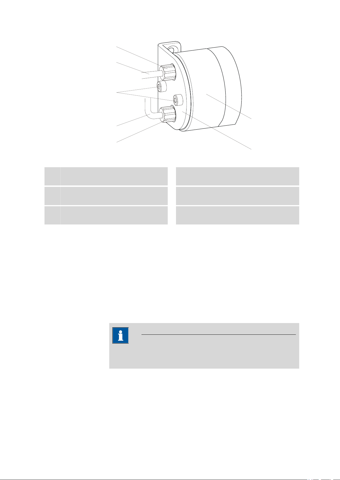
3.9 Eluent degasser
Gas bubbles in the eluent lead to an unstable baseline, as high pressure
pumps can transport liquids, but not gases. The eluent therefore has to be
degassed, before it reaches the high pressure pump.
The eluent degasser removes gas bubbles and dissolved gases from the
eluent. For degassing, the eluent flows into a vacuum chamber through a
special fluoropolymer capillary.
CO2 adsorber
4
Adsorbs CO2 from the air (e.g. Merck soda
lime with indicator, no. 6839.10).
Aspiration filter 6.2821.090
6
Clamping screw
8
From accessories set 6.2744.210.
Eluent bottle 6.1608.070
10
SGJ clip 6.2023.020
12
Threaded stopper
14
Note
The eluent degasser is already installed in the newly delivered instrument. The following installation instructions must only be followed, if
the connections to the degasser had to be disconnected for maintenance.
881 Compact IC pro – Anion – MCS
■■■■■■■■
29
Page 40

3.9 Eluent degasser
5
6
1
3
4
■■■■■■■■■■■■■■■■■■■■■■
Connecting the eluent degasser
Figure 13 Eluent degasser
Eluent degasser input
1
Tubing flare
3
With tubing nipple.
Eluent aspiration tubing (6.1834.080)
5
For aspirating the eluent. The clamping
screw (13-4) is firmly mounted.
1
■ Insert the eluent aspiration tubing (13-5) into the eluent degasser
■ Carefully tighten the clamping screw (13-4).
■ Insert connection capillary (13-6) (the end with the longer clamp-
2
■ Carefully tighten the clamping screw (13-4).
■ Connect the other end of the connection capillary (13-6) (with
Eluent degasser output
2
Clamping screw
4
Connection tubing (6.1834.090)
6
Connection from the eluent degasser to the
high pressure pump (see Chapter 3.10, page
31). The clamping screw (13-4) is firmly
mounted.
Caution
The clamping screws (13-4) must be tightened carefully. Use the
wrench (6.2621.050) to do this.
input (13-1).
ing screw (13-4)) into the eluent degasser output (13-2).
the shorter clamping screw ) to the high pressure pump (14-9)
(see "Connecting inlet to the high pressure pump", page 32).
■■■■■■■■
30
881 Compact IC pro – Anion – MCS
Page 41

■■■■■■■■■■■■■■■■■■■■■■
10
8
9
1
2
3
4
5
6
2
7
2
2
2
11
2
12
2
13
3.10 High pressure pump
The intelligent and low pulsation high pressure pump pumps the eluent
through the system. It is equipped with a chip on which its technical specifications and "life history" (operating hours, service data, … ) are saved.
The purge valve is used for deaerating (see Chapter 3.10.2, page 33)
the high pressure pump.
3.10.1 Capillary connections high pressure pump/purge valve
Note
All of the capillary connections of the high pressure pump and the
purge valve are already installed in the newly delivered instrument.
3 Installation
Connection capillary
1
PEEK capillary, connects main piston and
auxiliary piston.
Outlet valve holder
3
881 Compact IC pro – Anion – MCS
Figure 14
Capillary connections high pressure pump/purge valve
PEEK pressure screw, short
2
(6.2744.070)
Pump head (6.2824.110)
4
■■■■■■■■
31
Page 42

3.10 High pressure pump
5
1
2
3
4
■■■■■■■■■■■■■■■■■■■■■■
Fastening screws
5
For fastening the pump head.
Pump head inlet capillary
7
PEEK capillary at the input of the pump
head.
Coupling
9
For the connection of the eluent path at the
input of the high pressure pump. Can be
ordered together with the pressure screw
(14-8) under the number (6.2744.230).
Purge valve
11
For deaerating the high pressure pump.
With rotary knob in the center and pressure
sensor.
Connection capillary
13
Connects the output of the pump head with
the purge valve.
Note
Inlet valve holder
6
Pressure screw
8
For connecting a PEEK capillary to the coupling (14-9).
Deaerating capillary
10
For aspirating the eluent when deaerating
the high pressure pump (see Chapter
3.10.2, page 33).
Connection capillary
12
For connecting the inline filter (see Chapter
3.11, page 35).
The eluent aspiration capillary is already installed in the newly delivered
instrument. The following installation instructions need not be carried
out at the time of initial installation.
Connecting inlet to the high pressure pump
Figure 15
Pressure screw
1
For connecting the coupling (15-2) to the
pump head inlet capillary (14-7).
Can be ordered together with the coupling
under the number (6.2744.230).
High pressure pump – Connect inlet
Coupling (6.2744.230)
2
For connecting the eluent connection capillary (15-4) to the input of the high pressure
pump.
■■■■■■■■
32
881 Compact IC pro – Anion – MCS
Page 43

■■■■■■■■■■■■■■■■■■■■■■
3 Installation
Clamping screw
3
Backup ring
5
Eluent aspiration tubing
4
Eluent aspiration tubing (6.1834.080) or
(6.1834.090).
1
Connecting coupling
Fasten the coupling (15-2) with a pressure screw (15-1) on the pump
head inlet capillary (14-7).
2
Connecting eluent aspiration tubing
Caution
The clamping screws must be tightened carefully. To tighten, grip
the coupling (15-2) with the key (6.2739.000) and grip the clamping screw (15-3) with the wrench (6.2621.050).
■ Plug the eluent aspiration tubing (15-4) into the coupling (15-2).
■ Tighten the clamping screw (15-3).
3.10.2 Deaerating the high pressure pump
The high pressure pump will only operate perfectly if the pump head contains no more air bubbles. Therefore it must be deaerated during initial
start-up and after every change of eluent.
Caution
The high pressure pump must not be deaerated before the initial startup (see Chapter 4.1, page 63).
Deaerate the high pressure pump as follows (see Figure 16, page 34):
Deaerate the high pressure pump
The instrument must be connected to the PC and switched on to deaerate
the high pressure pump.
881 Compact IC pro – Anion – MCS
■■■■■■■■
33
Page 44

3.10 High pressure pump
5
1
2
6
7
5
3
4
5
■■■■■■■■■■■■■■■■■■■■■■
Figure 16 Deaerate the high pressure pump
Syringe 10 mL (6.2816.020)
1
For aspirating the eluent.
Purging needle (6.2816.040)
3
PEEK pressure screws, short
5
(6.2744.070)
Purge valve rotary knob
7
Luer connector
2
Part of the purging needle (6.2816.040)
Deaerating capillary
4
Purge valve
6
1
Connecting the purging needle
■ Push the end of the purging needle (16-3) over the end of the
deaerating capillary (16-4) on the purge valve.
2
Connecting the syringe
■ Insert syringe (16-1) in the Luer connector (16-2) of the purging
needle (see Figure 16, page 34).
3
Opening purge valve
■ Open the rotary knob (16-7) by approx. ½ rotation counterclock-
wise.
4
Setting the flow rate
■ Start MagIC Net™ (if not yet started).
■ Ensure that the eluent aspiration tubing is immersed sufficiently in
the eluent.
■ Let the high pressure pump run.
■■■■■■■■
34
881 Compact IC pro – Anion – MCS
Page 45

■■■■■■■■■■■■■■■■■■■■■■
5
6
3.11 Inline filter
Between the purge valve and the pulsation absorber the inline filter
(6.2821.120) is installed as protection against particles.
Inline filters protect the separation column securely against possible contamination from the eluent. Inline filters can however also just as well be
used for the purpose of protecting the suppressor against contaminations
in the regeneration or rinsing solutions. The filter platelets with a pore size
of 2 µm can be replaced quickly and easily. They remove particles like e. g.
bacteria and algae from the solutions.
3 Installation
Aspirating eluent
■ Aspirate with the syringe (16-1) until bubble-free eluent flows into
the syringe.
Completing deaerating
■ Switch off high pressure pump.
■ Close rotary knob (16-7).
■ Remove syringe (16-1) from the Luer connector (16-2).
■ Pull the purging needle (16-3) out of the deaerating capillary
(16-4).
Note
The inline filter is already installed in the newly delivered instrument.
The following installation instructions need not be carried out at the
time of initial installation.
Installing the inline filter
Caution
Observe the flow direction marked on the filter housing for the connection of the inline filter.
881 Compact IC pro – Anion – MCS
■■■■■■■■
35
Page 46
3.12 Pulsation absorber
2 3
2 4
1
Figure 17 Connecting the inline filter
■■■■■■■■■■■■■■■■■■■■■■
Connection capillary
1
Connects the purge valve with the inline filter
Inline filter (6.2821.120)
3
Protects against particles.
Screw on the connection capillary running from the purge valve to
1
the input side of the inline filter using a pressure screw (6.2744.070).
Screw on the connection capillary running to the pulsation absorber
2
to the output side of the inline filter using a pressure screw
(6.2744.070).
3.12 Pulsation absorber
Note
PEEK pressure screws, short
2
(6.2744.070)
Connection capillary
4
Connects the inline filter with the pulsation
absorber.
■■■■■■■■
36
The pulsation absorber is already installed in the newly delivered instrument.
Caution
The pulsation absorber is maintenance-free and may not be opened.
The pulsation absorber protects the separation column from damage
caused by pressure fluctuations when switching the injection valve, and
reduces interfering pulsations during highly sensitive measurements. In
order to ensure these functionalities, it must be connected between the
high pressure pump (see Chapter 3.10, page 31) and injection valve (see
Chapter 3.14, page 39).
The pulsation absorber can be operated in both directions.
881 Compact IC pro – Anion – MCS
Page 47
■■■■■■■■■■■■■■■■■■■■■■
1
2
3
3
4
5
6
3 Installation
Figure 18 Pulsation absorber – Connection
Connection capillary
1
Connection to the inline filter.
PEEK pressure screws, short
3
(6.2744.070)
Pulsation absorber (6.2620.150)
5
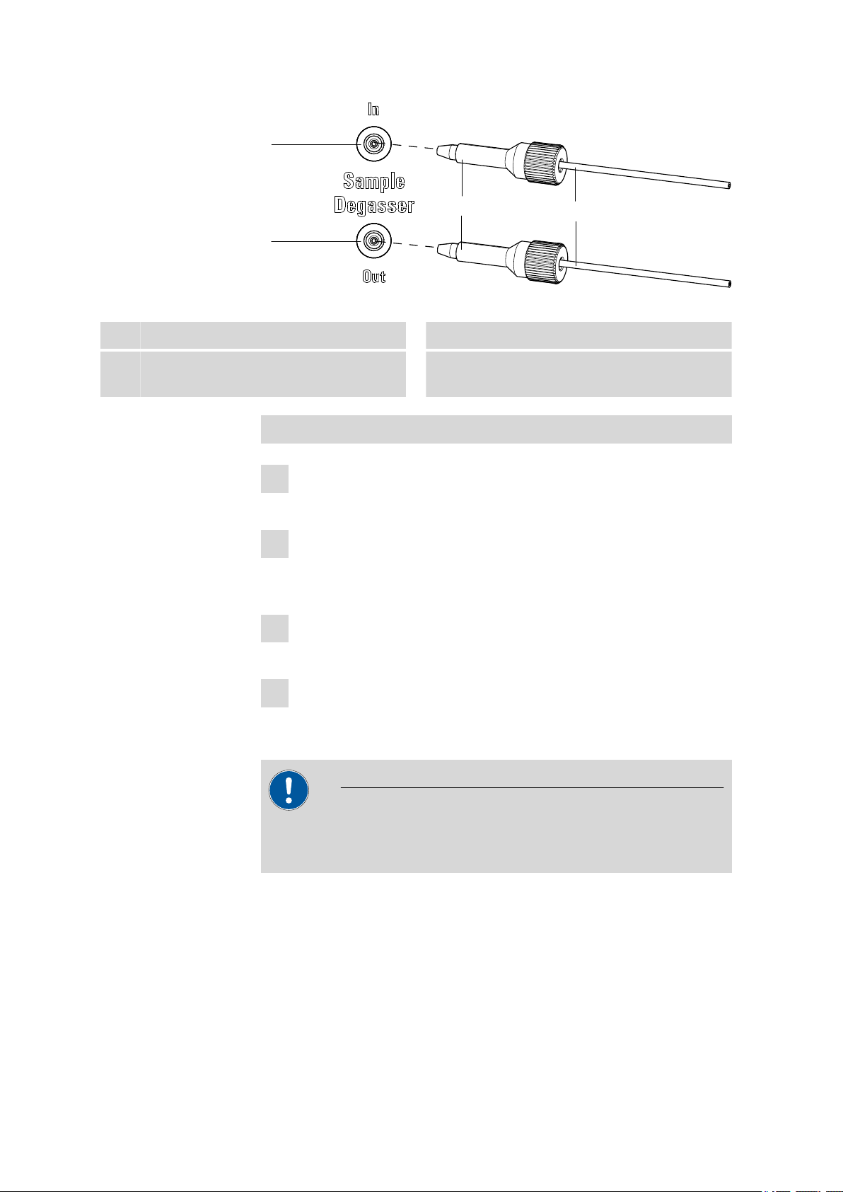
3.13 Sample degasser
The sample degasser removes gas bubbles and dissolved gases from the
sample. For degassing, the sample flows into a vacuum chamber through
a special fluoropolymer capillary.
Gas bubbles in the sample lead to poor reproducibility, as the quantity of
sample in the sample loop would not always be the same. Samples (containing gas) should therefore be degassed before injection. For this the
sample is sucked through a degasser chamber before injection, whereby
any gas bubbles are automatically removed.
Note
Fastening screws
2
Holder for pulsation absorber
4
Connection capillary
6
Connection to the injection valve.
When using the sample degasser, the rinsing time extends by at least 2
minutes.
881 Compact IC pro – Anion – MCS
■■■■■■■■
37
Page 48
3.13 Sample degasser
1
2
3
4
■■■■■■■■■■■■■■■■■■■■■■
Figure 19 Sample degasser
Sample degasser input
1
PEEK pressure screw, long
3
(6.2744.090)
Sample degasser output
2
Connection capillaries (6.1803.040)
4
Connecting the sample degasser
Remove and keep the threaded stoppers (6.2744.220) from the input
1
and output of the sample degasser.
Connect the end of the sample aspirating capillary (6.1803.040) con-
2
nected to the injection valve to the output of the sample degasser
(19-2), using a long PEEK pressure screw (19-3).
Connect the connection capillary (6.1803.040) to the input of the
3
sample degasser (19-1), using a long PEEK pressure screw (19-3).
Guide the other end of the connection capillary out of the instrument
4
through a capillary feed-through and connect it with the Sample Processor, if applicable.
Caution
If the sample degasser is not used, the input and output must be
sealed with the threaded stoppers (6.2744.220).
■■■■■■■■
38
881 Compact IC pro – Anion – MCS
Page 49

■■■■■■■■■■■■■■■■■■■■■■
1
2
3
4
5
6
2
4
5
7
7
3.14 Injection valve
The injection valve connects the eluent and sample path. Through rapid
and precise valve switchover a precise amount of sample solution defined
by the size of the sample loop is injected and rinsed with eluent onto the
separation column.
3.14.1 Connecting the injection valve
The injection valve has six connectors: two for the sample path (connectors 1 and 2), two for the eluent path (connectors 4 and 5) and two for
the sample loop (connectors 3 and 6).
Note
The capillaries of the eluent path and the sample path and the sample
loop are already installed in the newly delivered instrument.
3 Installation
Figure 20
Injection valve
1
Connection capillary
3
Connected to connector 4. Carries eluent to
the injection valve.
Connection capillary
5
Connected to connector 1. Carries sample to
the injection valve.
PEEK pressure screw 6.2744.010
7
881 Compact IC pro – Anion – MCS
Injection valve – connected
Sample loop
2
Connected to connectors 3 and 6.
Connection capillary (column inlet
4
capillary)
Connected to connector 5. Carries eluent to
the separation column.
Connection capillary
6
Connected to connector 2. Carries sample to
the waste container.
■■■■■■■■
39
Page 50

3.14 Injection valve
1
2
4 5
3 6
12
4 5
3 6
1
2
4
3
5
4
3
1
2
A B
■■■■■■■■■■■■■■■■■■■■■■
Replacing the sample loop
The sample loop can be replaced, depending on requirements. For additional information concerning selection of the appropriate sample loop,
see Chapter 3.14.3, page 41.
Note
Use only 6.2744.010 PEEK pressure screws for connecting capillaries
and sample loop to the injection valve.
1
Removing existing sample loop
■ Loosen 6.2744.010 pressure screws at connector 3 and connec-
tor 6.
■ Remove sample loop.
2
Mounting new sample loop
■ Fasten one end of the sample loop (20-2) with a 6.2744.010
PEEK pressure screw (20-7) to connector 3.
■ Fasten the other end of the sample loop (20-2) with a second
6.2744.010 PEEK pressure screw (20-7) to connector 6.
3.14.2 Mode of operation of the injection valve
The injection valve (see Figure 21, page 40) can adopt two valve positions - FILL and INJECT. Switching back and forth between the two valve
positions determines whether the sample path or the eluent path is guided through the sample loop. The following figure provides a schematic
display of the flow paths of the two valve positions.
Figure 21
Injection valve – Positions
Position FILL
A
■■■■■■■■
40
Position INJECT
B
881 Compact IC pro – Anion – MCS
Page 51

■■■■■■■■■■■■■■■■■■■■■■
3 Installation
Eluent input
1
Capillary coming from the high pressure
pump.
Sample input
3
Sample aspirating capillary.
Sample loop
5
Position A In the position FILL, the sample solution flows
Position B In the position INJECT, the eluent flows through
Eluent output
2
Capillary to the column.
Sample output
4
Capillary to waste container.
through the sample loop to the waste container.
The eluent flows directly to the separation column at the same time.
the sample loop to the separation column. If
sample solution is to be found in the sample
loop at the time of the valve switchover, then
this will be conveyed along with the eluent, thus
making its way to the separation column. The
flow in the sample path is either stopped or the
sample flows directly to the waste container.
3.14.3 Selecting the sample loop
The amount of sample solution injected depends on the volume of the
sample loop. The choice is made on the basis of the application. The following sample loops are normally used:
Cation determination
Anion determination with suppression 20 µL
Anion determination without suppression 100 µL
3.15 Column heater
The perfect isolation of the column chamber ensures thermally stable conditions for the separation column. The temperature of the column heater
can be set in the software.
10 µL
881 Compact IC pro – Anion – MCS
■■■■■■■■
41
Page 52

3.15 Column heater
1
2
2
3
4
■■■■■■■■■■■■■■■■■■■■■■
Figure 22 Column heater
Column holder
1
For engaging the column. With column
detection.
Holder plate
3
For fixing the capillaries that have been
threaded in.
Capillary recesses
2
For threading in the capillaries to be tempered
Capillary feed-throughs
4
For guiding the capillaries in and/or out of
the column chamber.
The column heater contains a column holder (22-1) equipped with chip
recognition. The separation column (see Chapter 3.21, page 60) is
clicked into the column holder with the chip.
The capillaries must be guided into and out of the column heater via suitable capillary feed-throughs (22-4).
■■■■■■■■
42
881 Compact IC pro – Anion – MCS
Page 53

■■■■■■■■■■■■■■■■■■■■■■
3 Installation
In order to bring the eluent to the required temperature, the capillaries
must be guided through the capillary recesses (22-2) before connection to
the separation column.
Note
The column input capillary is already installed in newly delivered instruments. The following installation instructions need not be carried out at
the time of initial installation.
Installing capillaries in the column heater
1
Opening column heater
Loosen the knurled screw(s) at the door to the column chamber and
open the door.
881 Compact IC pro – Anion – MCS
■■■■■■■■
43
Page 54

3.15 Column heater
1
2
4
2
Retracting capillaries
■■■■■■■■■■■■■■■■■■■■■■
Figure 23 Column heater – Installing capillaries
Column input capillary
1
Leading from the injection valve
Inner capillary recess
3
Screws
5
For fastening the holder plate
■ Slide the column input capillary (23-1) from below into the outer
Outer capillary recess
2
Holder plate
4
of the two capillary recesses (23-2). Slide it through under the
holder plate (23-4) until it emerges again at the top.
■■■■■■■■
44
881 Compact IC pro – Anion – MCS
Page 55

■■■■■■■■■■■■■■■■■■■■■■
3 Installation
■ Carefully bend the column input capillary (23-1) downward and
slide it from top to bottom through the inner capillary recess
(23-3) until it emerges at the lower edge of the holder plate
(23-4).
■ At the end of the column input capillary (23-1), connect the cou-
pling 6.2744.040 (first-time installation) or the guard column or
the separation column (after first-time start-up) (see "Connecting
and rinsing the guard column", page 60) or (see "Connecting
and rinsing the separation column", page 61).
Note
If it is difficult to slide the capillary under the holding plate, then
you can loosen the holding plate somewhat by undoing the
screws slightly. Carefully retighten the loosened screws as soon as
the capillary has been pulled into the recesses.
3
Closing the column chamber
Press the door to the column heater shut and close it tightly with the
knurled screws.
Note
When closing the door, take care to ensure that the capillaries are
in place in the capillary feed-throughs in the door and that they
are not squeezed shut.
3.16 Peristaltic pump
3.16.1 Principle of the peristaltic pump
The Peristaltic pump is used for pumping sample and auxiliary solutions. It
can rotate in both directions.
The peristaltic pump pumps liquids according to the principle of displacement. The pump tubing is clamped between the rollers (24-3) and the
tubing cartridge (24-5). During operation, the peristaltic pump drive
rotates the roller hub (24-2), so that the rollers (24-3) push the liquid forward in the pump tubing.
881 Compact IC pro – Anion – MCS
■■■■■■■■
45
Page 56

3.16 Peristaltic pump
6
4
3
5
7
■■■■■■■■■■■■■■■■■■■■■■
Figure 24 Peristaltic pump
Knurled screw in the mounting pin
1
Rollers
3
Tubing cartridges 6.2755.000
5
Snap-action lever
7
Roller hub
2
Cartridge holder
4
Contact pressure lever
6
■■■■■■■■
46
881 Compact IC pro – Anion – MCS
Page 57
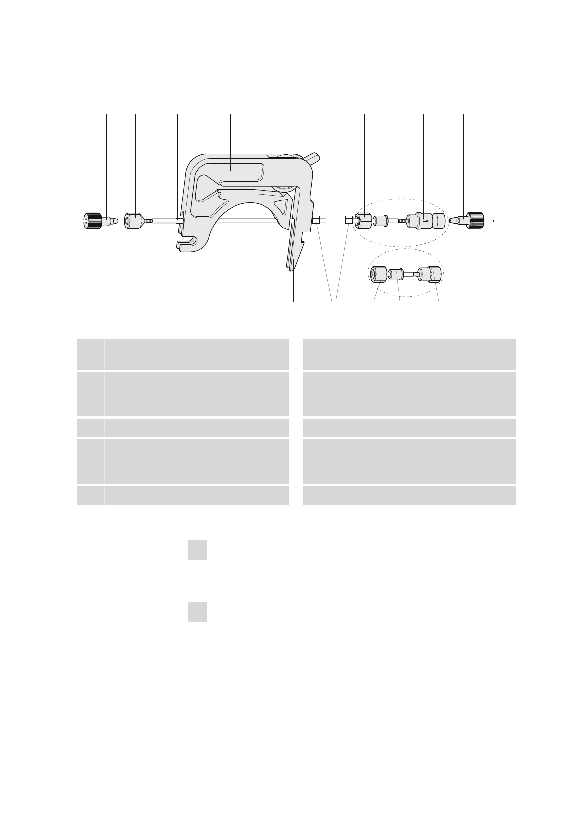
■■■■■■■■■■■■■■■■■■■■■■
6.2744.160
1
6.2744.180
2 3 4 5 6 7 8 1
9 10 3
6 7 8
3.16.2 Installing the peristaltic pump
Figure 25 Installing the pump tubing
3 Installation
PEEK pressure screws, short
1
(6.2744.070)
Stopper
3
The colors of the stopper indicate the inner
diameter of the pump tubing.
Contact pressure lever
5
Adapter
7
Pump tubing (6.1826.xx0)
9
2
4
6
8
10
Mount the pump tubing as follows:
1
Removing the tubing cartridge
Release the tubing cartridge from the cartridge holder by pressing
the snap-action lever and unhooking from the mounting pins (24-1).
2
Connecting the aspiration side
Place a 6.2744.034 tubing olive (25-2) on the aspiration side of the
pump tubing.
Tubing olive (6.2744.034)
Tubing cartridge (6.2755.000)
Union nut
Tubing olive
Either with filter holder (6.2744.180) or
without filter holder (6.2744.160).
Snap-action lever
881 Compact IC pro – Anion – MCS
■■■■■■■■
47
Page 58

3.16 Peristaltic pump
1
2
3
■■■■■■■■■■■■■■■■■■■■■■
3
Connecting the pressure side
Note
Depending on the use of the peristaltic pump, on the pressure side
you can either connect:
■ Case A: a 6.2744.180 pump tubing connection with filter
(see Figure 26, page 48) or
■ Case B: a 6.2744.160 pump tubing connection without filter
(see Figure 27, page 49).
For pumping the auxiliary solutions to the MSM or to the SPM, a
6.2744.180 pump tubing connection with filter must be used.
Case A: 6.2744.180 pump tubing connection with filter:
Union nut
1
Tubing olive with filter holder
3
Figure 26
■ Slide union nut (26-1) onto the pump tubing.
■ Select a suitable adapter (26-2) and slide it onto the pump tubing.
Install pump tubing connection with filter
Adapter
2
The type of adapter depends on the pump tubing (see Table 1,
page 49).
■ Place the tubing olive with filter holder (26-3) onto the pump tub-
ing.
■ Screw the union nut (26-1) onto the tubing olive (26-3).
or
Case B: 6.2744.160 pump tubing connection without filter:
■■■■■■■■
48
881 Compact IC pro – Anion – MCS
Page 59

■■■■■■■■■■■■■■■■■■■■■■
1
2
3
3 Installation
Figure 27 Install pump tubing connection without filter
1
3
Union nut
Tubing olive
Adapter
2
■ Slide union nut (27-1) onto the pump tubing.
■ Select a suitable adapter (27-2) and slide it onto the pump tubing.
The type of adapter depends on the pump tubing (see Table 1,
page 49).
■ Place the tubing olive (27-3) onto the pump tubing.
■ Screw the union nut (27-1) onto the tubing olive (27-3).
4
Inserting the pump tubing
■ Press the contact pressure lever all the way down.
■ Place the pump tubing in the tubing cartridge. The stoppers
(25-3) must snap into the corresponding holders of the tubing
cartridge.
5
Inserting the tubing cartridge
■ Hang the tubing cartridge in the mounting pin and press in the
cartridge holder until the snap-action lever snaps in.
6
Connecting the capillaries
■ Screw the respective capillaries tightly to the two tubing olives
with PEEK pressure screws (25-1).
881 Compact IC pro – Anion – MCS
Table 1 Pump tubings and suitable adapters
Pump tubing Adapter
6.1826.020 (blue/blue)
6.1826.310 (orange/green)
6.1826.320 (orange/yellow)
6.1826.330 (orange/white)
■■■■■■■■
49
Page 60

3.16 Peristaltic pump
■■■■■■■■■■■■■■■■■■■■■■
Pump tubing Adapter
6.1826.340 (black/black)
6.1826.360 (white/white)
6.1826.380 (gray/gray)
6.1826.390 (yellow/yellow)
Set flow rate
The contact pressure of the tubing cartridge must be adjusted in order to
regulate the flow rate. Proceed as follows:
Set the contact pressure
■ Fully loosen the contact pressure lever (25-5), i.e. press it all the
1
way down.
■ Switch on the peristaltic pump.
■ Raise the contact pressure lever one step at a time until liquid
flows.
■ When liquid starts flowing, raise the contact pressure lever by an
additional 2 ratchet increments.
The contact pressure is now set optimally.
The delivery rate depends not only on the correct contact pressure
but also on the interior diameter of the pump tubing and the rotational speed of the drive.
Note
Pump tubings are consumable material. The service life of the pump
tubings depends on the contact pressure amongst other factors.
■■■■■■■■
50
881 Compact IC pro – Anion – MCS
Page 61

■■■■■■■■■■■■■■■■■■■■■■
3.17 Metrohm Suppressor Module (MSM)
The MSM is used for chemical suppression during anion analysis with conductivity detection or UV/VIS detection. It consists of 3 suppressor units in
total, which are, in rotation, used for suppression – regenerated with
100 mmol/L sulfuric acid – rinsed with ultrapure water.
Suppression reaction in the MSM
When using a carbonate eluent, the following reaction (amongst others)
occurs in the MSM:
2R-SO
-H+
+ Na2CO3 ➙ 2R-SO
3
3.17.1 Connecting the suppressor
The three inputs and outputs of the suppressor units, numbered with 1, 2
and 3 on the connecting piece, each have 2 fixed mounted PTFE capillaries.
-Na+
+ H2O + CO
3
3 Installation
2
881 Compact IC pro – Anion – MCS
■■■■■■■■
51
Page 62
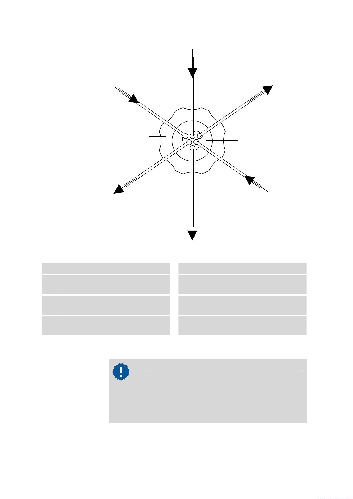
3.17 Metrohm Suppressor Module (MSM)
1
3
2
3
4
5
6
7
8
2
1
■■■■■■■■■■■■■■■■■■■■■■
Figure 28 Suppressor – connection capillaries
Union nut
1
Eluent inlet capillary
3
Labeled with in.
Rinsing solution inlet capillary
5
Labeled with rinsing solution.
Regeneration solution outlet capillary
7
Labeled with waste reg..
Connecting piece (6.2832.010)
2
Eluent outlet capillary
4
Labeled with out.
Rinsing solution outlet capillary
6
Labeled with waste rins..
Regeneration solution inlet capillary
8
Labeled with regenerant.
The rinsing solution and regeneration solution are pumped with a peristaltic pump (see Chapter 3.16, page 45).
Caution
To protect the suppressor against foreign particles or bacterial growth,
a pump tubing connection with filter (6.2744.180) (26-3) must be
mounted between the peristaltic pump and the inlet capillaries of the
suppressor.
■■■■■■■■
52
881 Compact IC pro – Anion – MCS
Page 63

■■■■■■■■■■■■■■■■■■■■■■
3 Installation
Connect the PTFE capillaries firmly mounted on the connecting piece to
the other components of the IC system as follows:
Connecting the capillaries of the suppressor
In order to protect the Suppressor from foreign particles or bacterial
growth, the following precondition must be fulfilled:
■ Pump tubing connections with filter (6.2744.180) are installed at the
pump tubing outlets of the peristaltic pump.
Caution
As the PTFE capillaries are very soft, the pressure screws should not be
overtightened.
Squeezed capillary ends can be shortened with the capillary cutter
(6.2621.080).
1
Connecting the eluent inlet capillary
■ Fasten the end of the inlet capillary labeled with in to the output
of the column with a short PEEK pressure screw (6.2744.070).
2
Connecting the eluent outlet capillary
Note
Depending on the instrument type, the suppressor is either connected directly with the detector or, if available and used, with the
MCS.
■ Connect the output capillary labeled with out either with the
detector (see manual of the detector).
or
■ Connect the output capillary labeled with out with the input in of
the MCS, using a long PEEK pressure screw (6.2744.090).
3
Connecting the rinsing solution inlet capillary
■ With a short PEEK pressure screw (6.2744.070), fasten the end of
the inlet capillary labeled with rinsing solution to the pump tubing connection of the pump tubing which carries the rinsing solution.
881 Compact IC pro – Anion – MCS
■■■■■■■■
53
Page 64

3.18 Metrohm CO2 Suppressor (MCS)
■■■■■■■■■■■■■■■■■■■■■■
4
Connecting the rinsing the solution outlet capillary
■ Guide the other end of the outlet capillary labeled with waste
rins. into a sufficiently large waste container and fasten it there.
5
Connecting the regeneration solution inlet capillary
■ With a short PEEK pressure screw (6.2744.070), fasten the end of
the inlet capillary labeled with regenerant to the pump tubing
connection of the pump tubing which carries the regeneration
solution.
6
Connecting the regeneration solution outlet capillary
■ Guide the other end of the outlet capillary labeled with waste
reg. into a sufficiently large waste container and fasten it there.
3.18 Metrohm CO
Suppressor (MCS)
2
3.18.1 General information on the MCS
The Metrohm CO2 Suppressor (MCS) removes the CO2 from the eluent
flow. This reduces the background conductivity, improves the detection
sensitivity and minimizes the injection and carbonate peaks.
CO2 can reach the eluent flow through the sample itself or arise through
the suppression reaction in the MSM/. The CO2 peak is effectively minimized through connection of the MCS between the MSM and detector.
The principle of the MCS is based on the gas permeability of the fluoropolymer membrane inside the degassing cell of the MCS. The eluent is guided
through a capillary with a fluoropolymer membrane inside the degassing
cell. A vacuum is generated in the degassing cell by the pump, at the
same time, the pump sucks CO2-free air – ambient air is aspired through a
CO2 adsorption cartridge (30-4), which removes the CO2 . The pressure
and concentration difference in the degassing cell in comparison to the
inside of the capillary now causes the CO2 to diffuse out of the eluent
flow.
3.18.2 Connecting MCS
The MCS is connected between the MSM and detector.
■■■■■■■■
54
881 Compact IC pro – Anion – MCS
Page 65

■■■■■■■■■■■■■■■■■■■■■■
1
2
3
4 4
5 5
6
7
Figure 29 MCS – connection
3 Installation
MCS input
1
Connection to the MSM.
Aspirating capillary
3
For aspirating air low in CO2 (as a result of
CO2 adsorption cartridge (30-4)).
Capillary connection
5
Luer coupling (6.2744.120)
7
Mounted on the air aspirating capillary with
pressure screw 6.2744.070.
Connecting the MCS
1
Connecting the MSM
Connect the eluent outlet capillary (labeled with out) to the MCS
inlet (29-1) using a long PEEK pressure screw (6.2744.090) (29-4).
2
Connection to the detector
Connect the detector inlet capillary to the MCS output (29-2) using a
long PEEK pressure screw (6.2744.090) (29-4).
MCS output
2
Connection to the detector.
PEEK pressure screw, long
4
(6.2744.090)
Pressure screw, short (6.2744.070)
6
Mounted on the air aspirating capillary.
Caution
If the MCS is not used, the input and output must be sealed with
6.2744.220 stoppers.
881 Compact IC pro – Anion – MCS
■■■■■■■■
55
Page 66

3.18 Metrohm CO2 Suppressor (MCS)
9
3
8 7
3
1
2 3
3
4
5
6
3.18.3 Installing the adsorption cartridges
For effective CO2 removal, the air sucked through the degassing cell
should be as low in CO2 as possible. To achieve this, the air is aspirated
through a CO2 adsorption cartridge (6.2837.000) (30-4)..
Moisture can block the CO2 adsorption cartridge. In order to prevent this,
a H2O adsorption cartridge (6.2837.010) (30-7) is connected upstream.
■■■■■■■■■■■■■■■■■■■■■■
Figure 30 Adsorption cartridge holder
PEEK pressure screw, short
1
(6.2744.070)
Clips
3
For fastening the adsorption cartridges.
Adapter (6.1808.190)
5
For connecting the H2O adsorption cartridge
and CO2 adsorption cartridge.
■■■■■■■■
56
Luer coupling (6.2744.120)
2
CO2 adsorption cartridge (6.2837.000)
4
For removing the CO2 from the aspirated air.
3-layer filled, blue-brown-gray.
PVC tubing
6
For connecting the H2O adsorption cartridge
and CO2 adsorption cartridge.
881 Compact IC pro – Anion – MCS
Page 67

■■■■■■■■■■■■■■■■■■■■■■
3 Installation
H2O adsorption cartridge (6.2837.010)
7
For removing the H2O from the aspirated air.
Filled with bead desiccant.
MCS aspirating capillary
9
Connection to the MCS. Corresponds to
(29-3).
Installing the adsorption cartridges
1
Preparing the adsorption cartridge holder
Push the 4 clips (30-3) into the slot of the adsorption cartridge
holder (30-8).
2
Removing the caps
■ Remove the two sealing caps at the tip of the two cartridges.
■ In the case of the H
3
Connecting the CO2 adsorption cartridge
■ Insert the CO
■ Click the CO
4
Connecting the PVC tubing
■ Insert the adapter (30-5) into the CO
■ Fasten the PVC tubing (30-6) on the adapter (30-5).
5
Connecting the H2O adsorption cartridge
■ Place the H
■ Click the H
6
Placing the adsorption cartridge holder in the instrument
■ Place the adsorption cartridge holder with cartridges into the
Adsorption cartridge holder
8
(6.2057.080)
O adsorption cartridge, replace the round
2
sealing cap on the larger end with the star-shaped sealing cap.
adsorption cartridge into the coupling (30-2) on
2
the end of the MCS aspirating capillary (3-15).
adsorption cartridge into the two lower clips (30-3)
2
of the adsorption cartridge holder (30-8).
adsorption cartridge.
2
O adsorption cartridge into the PVC tubing (30-6).
2
O adsorption cartridge into the two upper clips (30-3)
2
of the adsorption cartridge holder (30-8).
detector chamber of the instrument
881 Compact IC pro – Anion – MCS
■■■■■■■■
57
Page 68

3.19 Connecting the instrument
3.19 Connecting the instrument
3.19.1 Connecting the instrument to the PC
Note
The instrument must be switched off when connecting the PC.
1
Connecting the USB cable
Connect the PC connection socket of the instrument to a USB connector of the computer via the (6.2151.020) USB cable.
3.19.2 Connecting the instrument to mains supply
Warning
■■■■■■■■■■■■■■■■■■■■■■
The power supply unit must not get wet. Protect it against the direct
effect of liquids.
Mains cable
Which mains cable is supplied depends on the location:
■ 6.2122.020 with plug SEV 12 (Switzerland, …)
■ 6.2122.040 with plug CEE(7), VII (Germany, …)
■ 6.2122.070 with plug NEMA 5-15 (USA, …)
The mains cable is three-core and provided with a plug with grounding. If
another plug has to be mounted, the yellow/green conductor (IEC standard) must be connected to the protective ground (protection class I).
1
Connecting the mains cable
■ Plug the mains cable into the mains connection socket .
■ Connect the mains cable to the mains supply.
2
Switching on the instrument
Switch on the instrument using the mains switch .
After switching on, the LED on the front of the instrument flashes
while a system test is carried out and the connection to the software
is established. Once the system test is complete and the connection
to the software has been established, the LED lights up continuously.
■■■■■■■■
58
881 Compact IC pro – Anion – MCS
Page 69

■■■■■■■■■■■■■■■■■■■■■■
3.20 Guard column
The use of guard columns serves for protecting the separation columns
and increasing their service life considerably. The guard columns available
from Metrohm represent either actual guard columns or are so-called
guard column cartridges which are used together with a cartridge holder.
The installation of a guard column cartridge in the associated holder is
described in the leaflet of the guard columns.
Information regarding which guard column is suitable for your separation column can be found in the Metrohm IC Column Program
(which is available from your Metrohm agent), the leaflet provided
along with your separation column, the product information on the
separation column at http://www.metrohm.com (product area Ion
Chromatography), or obtained directly from your agent.
3 Installation
Note
Caution
New guard columns are filled with solution and are sealed on both
sides with stoppers or caps, respectively. Before using the guard column, you need to ensure that this solution is miscible with the eluents
used (observe manufacturer's data).
Note
The guard column may only be installed after the initial start-up (see
Chapter 4.1, page 63) of the instrument. Until then, use the coupling
(6.2744.040) instead of the guard and separation column.
Note
Metrohm recommends, always to work with guard columns. These protect the separation column and can be exchanged regularly.
881 Compact IC pro – Anion – MCS
■■■■■■■■
59
Page 70

3.21 Separation column
■■■■■■■■■■■■■■■■■■■■■■
Connecting and rinsing the guard column
1
Connecting the guard column
Caution
When inserting the guard column, always ensure that it is inserted
correctly corresponding to the flow direction (if indicated).
■ Remove sealing caps and/or stoppers from the guard column.
■ Fasten the input of the guard column to the column inlet capillary
using a short PEEK pressure screw (6.2744.070).
■ In case the guard column is mounted on the separation column
with a connecting capillary, connect the included connection
capillary, which is included with the guard column, to the output
of the guard column using the PEEK pressure screw, which is .also
included.
2
Rinsing the guard column
■ Place beaker under the outlet capillary of the guard column.
■ Set the flow rate of the high pressure pump according to the data
given in the leaflet of the separation column.
■ Start the high pressure pump and rinse the guard column approx.
5 minutes with eluent.
■ Switch off the high pressure pump again.
3.21 Separation column
The intelligent separation column (iColumn) is the heart of the ion chromatographic analysis. It separates the different components corresponding to their interactions with the column. Metrohm separation columns
are equipped with a chip on which their technical specifications and their
history (first use / setting up, operating hours, injections, …) are saved.
Information regarding which separation column is suitable for your
application can be found in the Metrohm IC Column Program, the
product information for your separation column at http://
www.metrohm.com in the product area ion chromatography, or
obtained directly from your agent.
■■■■■■■■
60
Note
881 Compact IC pro – Anion – MCS
Page 71

■■■■■■■■■■■■■■■■■■■■■■
3 Installation
Caution
New separation columns are filled with solution and are sealed on both
sides with stoppers. Before using the column, you need to ensure that
this solution is miscible with the eluents used (observe manufacturer's
data).
You can find the separation columns and guard columns currently available from Metrohm in the Metrohm IC Column Program, or in the Internet
at http://www.metrohm.com in the product area Ion Chromatography. A
test chromatogram and an leaflet are provided along with each column.
You can request detailed information on special IC applications in the corresponding "Application Bulletins" or "Application Notes", available
in the Internet at http://www.metrohm.com in the Applications area or via
the Metrohm agent responsible free of charge.
Note
The separation column may only be installed after the initial start-up
(see Chapter 4.1, page 63) of the instrument. Until then, use the coupling (6.2744.040) instead of the guard and separation column.
Connecting and rinsing the separation column
1
Connect the separation column
Caution
When inserting the columns, always ensure that these are correctly inserted corresponding to the flow direction indicated.
■ Remove stoppers from the separation column.
■ Attach the guard column to the input of the separation column.
OR
Connect the input of the separation column to the outlet capillary
of the guard column, using the PEEK pressure screw (6.2744.070)
included.
OR
If no guard column is used (not recommended), connect the column input capillary to the input of the separation column, using a
PEEK pressure screw (6.2744.070).
881 Compact IC pro – Anion – MCS
■■■■■■■■
61
Page 72

3.21 Separation column
■■■■■■■■■■■■■■■■■■■■■■
2
Rinsing the separation column
■ Place beaker under the outlet end of the separation column.
■ Set the flow rate of the high pressure pump according to the data
given in the leaflet of the separation column.
■ Start the high pressure pump and rinse the separation column
approx. 10 minutes with eluent.
■ Switch off the high pressure pump again.
3
Mounting the separation column
■ Fasten the column output capillary to the output of the separation
column using a PEEK pressure screw (6.2744.070).
■ Hang separation column with chip into the column holder.
Note
The iColumns are equipped with a chip on which their operating data is
saved. The chip has to be hooked into the chip holder provided for this
so that the column recognition can function.
■■■■■■■■
62
881 Compact IC pro – Anion – MCS
Page 73

■■■■■■■■■■■■■■■■■■■■■■
4 Start-up
The chapter Start-up is divided into 2 sections:
Initial start-up The initial start-up is carried out during the ini-
Conditioning Conditioning is carried out as a final installation
4.1 Initial start-up
The initial start-up is carried out during the initial installation. The entire
system is rinsed before guard column and separation column are installed.
4 Start-up
tial installation.
step and each time after the system is started.
Caution
The separation column and guard column may not be installed for the
initial start-up.
Make sure that the coupling (6.2744.040) is being used instead of the
columns.
Perform the following steps during the initial start-up:
1
Preparing the software
■ Start the PC program MagIC Net™.
■ Open the Equilibration tab in MagIC Net™.
■ Select (or create) a suitable method.
2
Preparing the instrument
■ Ensure that the eluent aspiration tubing is immersed in the eluent
and that there is enough eluent in the eluent bottle.
■ Ensure that the aspiration tubings for the auxiliary solutions
(regeneration solution and rinsing solution) are immersed into the
respective solutions and that the is enough solution in the bottles.
■ Switch on the instrument.
3
Starting equilibration
■ In MagIC Net™, start the equilibration.
881 Compact IC pro – Anion – MCS
■■■■■■■■
63
Page 74

4.2 Conditioning
■■■■■■■■■■■■■■■■■■■■■■
4
Deaerate the high pressure pump
■ Deaerate the high pressure pump(s) via the purge valve (see
Chapter 3.10.2, page 33).
5
Set the contact pressure of the peristaltic pump
Note
This work step needs to be performed only if a peristaltic pump is
being used.
■ If peristaltic pumps are used, set the contact pressure (see "Set
flow rate", page 50).
6
Rinsing the instrument without columns
■ Rinse the instrument (without columns) with eluent for 5 minutes.
The instrument is now ready for the installation of the columns (see Chapter 3.20, page 59).
4.2 Conditioning
After the installation and after switching on the instrument, the system
must be conditioned with eluent until a stable baseline is reached.
After a change of eluent (see Chapter 5.4.2.3, page 69), the conditioning time can lengthen considerably.
Conditioning the system
1
Preparing the software
Note
Caution
■■■■■■■■
64
Ensure that the flow set is not higher than the flow permissible for
the corresponding column (see column leaflet and chip data set).
■ Start the PC program MagIC Net™.
■ Open the Equilibration tab in MagIC Net™.
881 Compact IC pro – Anion – MCS
Page 75

■■■■■■■■■■■■■■■■■■■■■■
■ Select (or create) a suitable method.
2
Preparing the instrument
■ Ensure that the column is correctly mounted according to the
flow direction indicated on the label (arrow must point in the
direction of flow).
■ Ensure that the eluent aspiration tubing is immersed in the eluent
and that there is enough eluent in the eluent bottle.
■ Ensure that the aspiration tubings for the auxiliary solutions
(regeneration solution and rinsing solution) are immersed into the
respective solutions and that the is enough solution in the bottles.
3
Checking leak-tightness
■ In MagIC Net™, start the equilibration.
■ Check all capillaries and their connections from the high pressure
pump to the detector for signs of liquid escaping.
If eluent escapes anywhere, tighten the corresponding pressure
screw or loosen the connection, check the end of the capillary,
shorten it with a capillary cutter if necessary, and restore the connection.
4
Conditioning the system
Rinse the system with eluent until the required stability of the baseline is attained (normally 30 minutes).
4 Start-up
During this time, step the MSM to the next position every 10
minutes.
The instrument is now ready for measuring samples.
881 Compact IC pro – Anion – MCS
■■■■■■■■
65
Page 76

5.1 General notes
5 Operation and maintenance
5.1 General notes
5.1.1 Care
Warning
The instrument housing must not be opened by untrained personnel.
The instrument requires appropriate care. Excess contamination of the
instrument may result in functional disruptions and a reduction in the service life of the sturdy mechanics and electronics.
Caution
■■■■■■■■■■■■■■■■■■■■■■
Although this is prevented to a great extent by design measures, the
mains plug should be unplugged immediately if aggressive media has
penetrated the inside of the instrument, so as to avoid serious damage
to the instrument electronics. In such cases, the Metrohm Service must
be informed.
On the rear of the instrument, the drainage tubings must be mounted and
the leak sensor must be plugged in and activated as protection against
escaping liquids.
Spillages of chemicals and solvents should be cleaned up immediately. In
particular, the plug connections on the rear panel of the instrument (especially the mains plug) should be protected from contamination.
5.1.2 Maintenance by Metrohm Service
Maintenance of the instrument is best carried out as part of an annual
service, which is performed by specialist personnel from Metrohm. If
working frequently with caustic and corrosive chemicals, a shorter maintenance interval is recommended. The Metrohm service department offers
every form of technical advice for maintenance and service of all Metrohm
instruments.
■■■■■■■■
66
881 Compact IC pro – Anion – MCS
Page 77

■■■■■■■■■■■■■■■■■■■■■■
5.1.3 Operation
In order to avoid disturbing temperature influences, the entire system
including the eluent bottle must be protected against direct sunlight.
5.1.4 Shutting down
If the instrument is not used for a longer period, the whole IC system
(except the columns) must be rinsed salt free with methanol/ultrapure
water (1:4), in order to prevent eluent salts from forming crystals which
may cause subsequent damage.
Rinsing salt free the IC system
To rinse the system, proceed as follows:
Remove the separation column from the eluent path. Connect the
1
connection capillaries directly with each other using a coupling
(6.2744.040).
Rinse the IC system with methanol/ultrapure water (1:4) for 15
2
minutes.
5 Operation and maintenance
Caution
Rinse with eluent for at least 15 minutes at starting up again and before
connecting the guard column and separation column.
5.2 Capillary connections
5.2.1 Operation
All connections between injection valve, separation column and detector
must be as short as possible, have a low dead volume and be completely
leak-tight. The PEEK capillary after the detector must be free of blockages.
Only use PEEK capillaries with an internal diameter of 0.25 mm in the high
pressure range between the high pressure pump and the detector.
881 Compact IC pro – Anion – MCS
■■■■■■■■
67
Page 78

5.3 Door
5.3 Door
5.4 Eluent
5.4.1 Production
The chemicals used for the production of eluents should have a degree of
purity of at least "p.a.". Only ultra pure water (resistance > 18.2 MΩ *cm)
may be used for dilution (this generally applies for reagents which are
used in ion chromatography).
■■■■■■■■■■■■■■■■■■■■■■
Caution
The door is made of PMMA (polymethylmetacrylate). It must never be
cleaned with abrasive media or solvents.
Caution
Never use the door as a handle.
Newly produced eluents should always be microfiltered (filter 0.45 µm).
Caution
Only microfiltered (filter 0.45 µm) eluents may be used.
The composition of the eluent has a crucial effect on the chromatographic
analysis:
Concentration An increase in the concentration generally leads
to shorter retention times and faster separation,
but also to higher background conductivity.
pH pH changes result in shifts in the dissociation
equilibria and hence changes in the retention
times.
Organic solvents The addition of an organic solvent (e.g. metha-
nol, acetone, acetonitrile) to aqueous eluents
generally accelerates lipophilic ions.
■■■■■■■■
68
881 Compact IC pro – Anion – MCS
Page 79

■■■■■■■■■■■■■■■■■■■■■■
5.4.2 Operation
5.4.2.1 Supply bottle
The supply bottle with the eluent must be connected as indicated in chapter 3.8.1, page 25. This is above all important for eluents with volatile sol-
vents (e.g. acetone).
Moreover, condensation must also be prevented in the eluent bottle. Drop
formation can change the concentration ratio in the eluent.
5.4.2.2 Aspiration filter
To protect the IC system against foreign particles, we recommend aspirating the eluents via a 6.2821.090 aspiration filter (9-2). This aspiration filter
must be replaced should it show signs of yellow discoloration (but no later
than every 3 months).
In the case of very sensitive measurements, the eluent should be stirred
constantly with a magnetic stirrer.
5 Operation and maintenance
5.4.2.3
Changing the eluent
When changing the eluent, it must be ensured that no precipitates can
occur. Solutions following one another in direct succession must therefore
be miscible. If the system has to be rinsed organically, several solvents
with rising or falling lipophilia must be used.
5.5 High pressure pump
5.5.1 Protection
Caution
The pump head is filled ex works with methanol/ultrapure water. It
must be ensured that the eluent used is freely miscible with the solvent
remaining in the pump head.
To protect the high pressure pump against foreign particles, we recommend that the eluent undergoes a microfiltration (filter 0.45 µm) before
being aspirated via a 6.2821.090 aspiration filter (see "Assembling eluent
aspiration tubing", page 25).
881 Compact IC pro – Anion – MCS
Salt crystals between the piston and seal cause abrasion particles which
can find their way into the eluent. These lead to contaminated valves, a
rise in pressure and in extreme cases scratched pistons. It is therefore
essential to ensure that no precipitates can occur (see Chapter 5.4.2.3,
page 69).
■■■■■■■■
69
Page 80

5.5 High pressure pump
In order to spare the pump seals, the pump should not be operated dry.
Therefore ensure that the eluent supply is correctly connected and that
there is enough eluent in the eluent bottle each time before switching
on the pump.
5.5.2 Maintenance
Maintenance work on the high pressure pump may not be carried out
unless the instrument is switched off.
Pump head maintenance
An unstable baseline (pulsation, flow fluctuations) is in many cases the
result of contaminated valves (37-2), (37-3) or defective, leaking piston
seals on the high pressure pump. Proceed as follows for cleaning contaminated valves and/or replacing worn parts such as pistons, piston seal and
valves:
■■■■■■■■■■■■■■■■■■■■■■
Caution
Caution
This maintenance work should be carried out at least once a year.
Removing the pump head
Switch off high pressure pump and wait until pressure is released.
1
Loosen the pressure screw on the inlet valve holder (14-6) and
2
unscrew the pump head input capillary (14-7), the coupling (14-9),
and the eluent aspiration tubing from the pump head.
In the process, eluent will spill. Hold the eluent aspiration tubing up
high and allow the eluent to flow back into the eluent bottle.
Unscrew the pump head outlet capillary (14-13) from the pump
3
head.
Remove pump head from the pump housing by loosening the 4 fas-
4
tening screws (14-5) using the hexagon key (6.2621.030). The main
piston is on the left (viewed from the front), and the auxiliary piston
is on the right.
■■■■■■■■
70
881 Compact IC pro – Anion – MCS
Page 81

■■■■■■■■■■■■■■■■■■■■■■
2
1
5 Operation and maintenance
Cleaning/replacing the zirconium oxide piston
Clean one piston after the other as follows:
1
Removing the piston cartridge from the pump head
Loosen the piston cartridge with a wrench and unscrew from the
pump head by hand.
1
Pump head
Figure 31 Pump head – removing the piston
Piston cartridge
2
2
Dismantling the piston
Caution
On the inside of the piston cartridge there is a taut spring than can
jump out of the piston cartridge if suddenly loosing tension.
When opening the piston cartridge, hold pressure towards the
spring and unscrew carefully.
■ Loosen the screw of the piston cartridge with a wrench and
unscrew carefully by hand and by holding pressure towards the
taut spring.
■ Remove the zirconium oxide piston and lay on a tissue.
■ Remove the spring retainer, spring and the inner plastic sleeve
from the piston cartridge and lay by.
881 Compact IC pro – Anion – MCS
■■■■■■■■
71
Page 82

5.5 High pressure pump
1 2
3
4
5 6
7
8
■■■■■■■■■■■■■■■■■■■■■■
■ Remove the backup ring from the pump head and lay to the other
parts.
Figure 32 Components of the piston cartridge
Piston cartridge screw
1
Zirconium oxide piston with piston
3
shaft
Order number: 6.2824.070
Spring
5
Order number: 6.2824.060
Piston cartridge
7
3
4
Retaining washer
2
Spring retainer
4
Inner plastic sleeve
6
Protects from metallic abrasion.
Backup ring
8
Cleaning the components of the piston
■ Clean zirconium oxide pistons contaminated by abrasion or
deposits with fine abrasive cleaning powder, rinse particle free
with ultrapure water and dry.
Replace highly contaminated or scratched zirconium oxide pistons
(spare part: 6.2824.070 zirconium oxide piston).
■ Rinse the other parts of the piston and dry with a lint-free cloth.
Assembling the piston
■ Insert the inner plastic sleeve, spring and spring retainer into the
piston cartridge.
■ Slide the zirconium oxide piston carefully into the piston cartridge
until its tip emerges from the small opening of the piston cartridge.
■ Attach screw and tighten by hand.
■■■■■■■■
72
Replacing the piston seal
The special tool (6.2617.010) (see Figure 33, page 73) is necessary to
remove the piston seal from the pump head. It consists of two parts: a tip
881 Compact IC pro – Anion – MCS
Page 83

■■■■■■■■■■■■■■■■■■■■■■
2
1
5 Operation and maintenance
for removing the old piston seal and a sleeve for inserting the new piston
seal.
Figure 33 Tool for piston seal
Pin
1
Tip for removing the old piston seal.
Sleeve
2
Sleeve for inserting the new piston seal.
Caution
Screwing the special tool for the piston seal (6.2617.010) into the piston seal destroys this completely!
1
Removing the piston seal
Caution
Avoid touching the sealing surface in the pump head (14-4) with
the tool.
Screw the special tool for the piston seal (33-1) with the narrow side
just as far into the piston seal as the same can be removed.
881 Compact IC pro – Anion – MCS
■■■■■■■■
73
Page 84

5.5 High pressure pump
1
2
1
2
■■■■■■■■■■■■■■■■■■■■■■
Figure 34 Removing the piston seal
Piston seal
1
2
Tool for piston seal (6.2617.010)
1
Sleeve for inserting the new piston seal.
Tool for piston seal
2
Pin of the tool.
Inserting the new piston seal into the tool
Insert the new piston seal tightly by hand into the recess of the
sleeve of the tool for the piston seal (33-2). The sealing springs must
be visible from the outside.
Figure 35 Inserting the piston seal into the tool
Piston seal
2
Order number: 6.2741.020
■■■■■■■■
74
3
Inserting the new piston seal into the pump head
Guide the sleeve of the tool for the piston seal (33-2) with inserted
piston seal into the pump head and press the seal with the wide end
of the tool for the piston seal (33-1) into the pump head recess.
881 Compact IC pro – Anion – MCS
Page 85

■■■■■■■■■■■■■■■■■■■■■■
1
2
5 Operation and maintenance
Figure 36 Inserting the piston seal into the pump head
4
Replacing the piston cartridge
Screw the assembled piston cartridge back into the pump head and
tighten, first by hand, then additionally by approx. 15° with a
wrench.
Cleaning the inlet valve and outlet valve
1
Removing valves
■ Unscrew the connection capillary for the auxiliary piston (14-1)
from the outlet valve holder.
■ Unscrew the holders for the inlet and outlet valves and remove
the valves (37-3) and (37-2).
881 Compact IC pro – Anion – MCS
■■■■■■■■
75
Page 86

5.5 High pressure pump
1
2
3
4
■■■■■■■■■■■■■■■■■■■■■■
Figure 37 Removing valves
Outlet valve holder
1
Inlet valve
3
Order number: 6.2824.170
Outlet valve
2
Order number: 6.2824.160
Inlet valve holder
4
2
Cleaning undissected valve
Clean contaminated or blocked valves initially without dismantling
them completely.
■ Rinse the valve in eluent flow and counterflow direction using a
spray bottle filled with ultrapure water, RBS solution or acetone.
■ The rinsing effect is further increased through a short treatment
(lasting for a maximum of 20 s) in an ultrasonic bath.
Note
Longer lasting ultrasonic baths can damage the ruby ball of the
valve.
Only if this cleaning is useless, dismantle the valves separately and
clean the components.
3
Dismantling valve
Dismantle every valve separately.
■■■■■■■■
76
Note
For dismantling the valve the tool for valve cartridges (6.2617.020)
is required.
881 Compact IC pro – Anion – MCS
Page 87

■■■■■■■■■■■■■■■■■■■■■■
1
3
4
2
5 Operation and maintenance
■ Place the valve with the seal faced downwards above the recess
in the holder.
■ Push the valve components out of the valve housing using the
needle of the tool.
Figure 38 Dismantling valve
Needle
1
For pushing the valve components out of
the valve housing.
Recess
3
For collecting the valve components.
The components of the valve are collected in the recess of the
holder.
The components of the valve are very small. In order not to lose
them, put the components into a dish.
■ The inlet valve and the outlet valve consist of the same, just differ-
valve
2
Holder
4
Note
ently arranged components (see Figure 39, page 78).
881 Compact IC pro – Anion – MCS
■■■■■■■■
77
Page 88

5.5 High pressure pump
1
2
3
5
6
7
8
9
10
9
8
7
10
5
4
6
■■■■■■■■■■■■■■■■■■■■■■
Figure 39 Components of the inlet valve and outlet valve
Inlet valve (6.2824.170)
1
Inlet valve housing
3
Sealing ring (black)
5
Sapphire sleeve
7
The shiny side must point to ruby ball.
Ceramic holder for ruby ball
9
4
Cleaning the components of the valve
Outlet valve (6.2824.160)
2
Outlet valve housing
4
Sleeve
6
Ruby ball
8
Seal
10
The larger opening must point outwards.
Rinse the valve components with ultrapure water and/or acetone and
dry with a lint-free cloth.
5
Reassembling the valve
Reassemble valve components according to figure 39, page 78.
■ Insert the seal with the larger opening faced downwards into the
recess of the tool.
■ Lay the other valve components above another in the correct
sequence (see Figure 39, page 78).
■■■■■■■■
78
881 Compact IC pro – Anion – MCS
Page 89

■■■■■■■■■■■■■■■■■■■■■■
5 Operation and maintenance
■ Place over the valve housing and hold it tightly.
■ By tilting the tool, the valve components slide into the valve hous-
ing.
■ Press the seal by hand well on the valve housing.
6
Checking the flow direction
Rinse the valve in the direction of the arrow on the valve housing and
check wether liquid is escaping on the other end.
If this is not the case, the valve has to be dismantled again and be
reassembled correctly (see Figure 39, page 78).
7
Inserting the valves back into the pump head
Caution
If by mistake, the inlet valve is mounted instead of the outlet valve,
an extreme pressure builds up within the working cylinder, which
can destroy the piston seal!
When inserting the valves, please take into account that the liquid
is being pumped through the pump head from bottom to top.
■ Insert the inlet valve into the inlet valve holder the way the seal is
visible.
■ Screw the inlet valve holder into the bottom of the pump head
and tighten with a wrench (37-4).
■ Insert the outlet valve into the outlet valve holder the way the seal
is visible.
■ Screw the outlet valve holder into the top of the pump head and
tighten with a wrench (37-1).
881 Compact IC pro – Anion – MCS
■■■■■■■■
79
Page 90

5.6 Inline filter
1 2 3
4
1
5
5
■■■■■■■■■■■■■■■■■■■■■■
Mounting the pump head
Note
To prevent the pump head from being positioned the wrong way, it is
provided with different bore hole depths for the fastening bolts, i. e. a
fastening bolt is longer than all others. The bore hole with the greatest
depth must therefore be assigned to the longest bolt. If this is not the
case, the pump will not function perfectly.
1
Mount the pump head on the pump again using the four fastening
screws (14-5). Firmly tighten the screws with the hexagon key
(6.2621.030).
Screw connection capillaries (14-1), (14-7) and (14-13) onto the
2
pump head again.
5.6 Inline filter
5.6.1 Maintenance
The inline filter (6.2821.120) comprises the filter housing (40-2), the filter
screw (40-4) and the filter (40-3). New filters (40-3) are available under
the order number 6.2821.130 (10 items).
The filters (6.2821.130) (40-3) should be changed every 3 months (more
frequently at higher backpressure).
Figure 40
1
3
Change filters (of the inline filter)
PEEK pressure screws, short
(6.2744.070)
Filter (6.2821.130)
Packaging contains 10 items.
Filter housing
2
Housing of the inline filter. Part of the
6.2821.120 accessories.
Filter housing
4
Screw of the inline filter. Part of the
6.2821.120 accessories.
■■■■■■■■
80
Connection capillaries
5
881 Compact IC pro – Anion – MCS
Page 91

■■■■■■■■■■■■■■■■■■■■■■
5 Operation and maintenance
Changing the filter
The flow must be stopped before changing the filter.
1
Removing the inline filter
■ Unscrew the pressure screws (40-1) from the inline filter.
2
Unscrewing the filter screw
■ Screw the filter screw (40-4) out of the filter housing (40-2) with
the aid of two adjustable wrenches (6.2621.000).
3
Inserting the filter
■ Remove the old filter (40-3) using tweezers.
■ Place the new filter (40-3) flat in the filter housing (40-2) using
tweezers.
4
Mounting filter screw
■ Screw the filter screw (40-4) back into the filter housing (40-2)
and tighten by hand. Then additionally tighten slightly with two
adjustable wrenches (6.2621.000).
5
Remounting the inline filter
■ Screw pressure screws (40-1) back onto the inline filter.
6
Rinsing the inline filter
■ Dismantle the guard column (if present) and the separation col-
umn and replace with a coupling (6.2744.040).
■ Rinse the instrument with eluent.
881 Compact IC pro – Anion – MCS
■■■■■■■■
81
Page 92

5.7 Sample degasser
5.7 Sample degasser
5.7.1 Operation
If you are working with sample degassing, the longer "transfer time" (see
Ascertaining the transfer time, page 83) means that it is also necessary
to rinse for longer (with the subsequent sample). The rinsing time should
be at least 3 times the "transfer time" so as to minimize the carry-over
effects. The "transfer time" itself depends on the pump capacity, total
capillary volume and volume of gas removed (i.e. the amount of gas in the
sample).
Note
When using the sample degasser, the rinsing time extends by at least 2
minutes.
■■■■■■■■■■■■■■■■■■■■■■
5.8 Inline sample preparation
To protect the separation column (see Chapter 3.21, page 60) against foreign particles which can affect the separating efficiency, we recommend
that all samples undergo a microfiltration (filter 0.45 µm). The ultrafiltration cell can be used for filtration (see manual of the IC Equipment for
Ultrafiltration).
Samples containing significant amounts of gas should be degassed. The
sample degasser (see Chapter 3.13, page 37) is used for degassing.
Matrix-loaded samples (e.g. blood, oil) should be prepared for the measurement by means of dialysis (see manual on the IC Equipment for Dialy-
sis).
If the concentration of the sample is too high, the sample should be dilu-
ted before feeding (see documentation on the IC Equipment for Sample
Dilution).
For an overview of all Metrohm inline sample preparation methods go to
the following website:http://misp.metrohm.com
■■■■■■■■
82
881 Compact IC pro – Anion – MCS
Page 93

■■■■■■■■■■■■■■■■■■■■■■
5.9 Rinsing the sample path
Before a new sample can be measured, the sample path must be rinsed
with it so that the measuring result is not falsified by the previous sample
(Sample carry-over).
In the case of automated sample feeding, the rinsing time should be at
least 3 times the transfer time.
The transfer time is the time required by the sample to flow from the sample vessel to the end of the sample loop. The transfer time depends on the
pump capacity of the peristaltic pump or the Dosino used, the total capillary volume and the volume of the gas removed by the sample degasser (if
used) - in other words the amount of gas in the sample.
Ascertaining the transfer time
To ascertain the transfer time, proceed as follows:
1
Emptying the sample path
Pump air through the sample path (pump tubing, tubing connections, capillary in the degasser, sample loop) for several minutes until
all liquid is displaced by the air.
2
Aspirating the sample and measuring time
Aspirate a sample typical for the later application and use a stop
watch to measure the time required by the sample to travel from the
sample vessel to the end of the sample loop.
5 Operation and maintenance
881 Compact IC pro – Anion – MCS
The time measured corresponds to the "transfer time". The rinsing
time should be at least 3 times the transfer time.
Checking the rinsing time
It is possible to determine whether the rinsing time is adequate via a direct
measurement of the sample carry-over. Proceed as follows:
1
Preparing two samples
■ Sample A: A typical sample for the application.
■ Sample sample B: Ultrapure water.
2
Determining "Sample A"
Let "Sample A" pass through the sample path for the duration of the
rinsing time, then inject and measure.
■■■■■■■■
83
Page 94

5.10 Injection valve
3
Determining "Sample B"
Let "Sample B" pass through the sample path for the duration of the
rinsing time, then inject and measure.
4
Calculating the sample carry-over
The degree of the sample carry-over corresponds to the ratio of the
peak areas of the measurement for sample B to the measurement for
sample A. The lower the ratio, the lower the sample carry-over. This
ratio can be modified by varying the rinsing time – thus allowing the
rinsing time required for the application to be ascertained.
5.10 Injection valve
5.10.1 Protection
To prevent contamination of the injection valve, a 6.2821.120 inline filter
(see Chapter 3.11, page 35) should be mounted between the high pressure pump and the pulsation damper.
■■■■■■■■■■■■■■■■■■■■■■
5.11 Peristaltic pump
5.11.1 Operation
The pumping capacity of the peristaltic pump depends on the drive speed
(set via software), the contact pressure and, above all, the internal diameter of the pump tubing. Depending on the application, different pump
tubings are used.
The service life of the pump tubings also depends on the contact pressure. Therefore fully lift the tubing cartridges by loosening the snapaction lever (25-10) on the right-hand side if the peristaltic pump is to
be turned off for a longer period. Once set, the contact pressure
remains unaffected.
The 6.1826.xxx pump tubings consist of PVC or PP and therefore must
not be used for rinsing with solutions containing acetone. In this case,
use other pump tubings or use another pump for rinsing.
Caution
Caution
■■■■■■■■
84
881 Compact IC pro – Anion – MCS
Page 95

■■■■■■■■■■■■■■■■■■■■■■
5.11.2 Maintenance
5.11.2.1 Pump tubing
The pump tubing used in the peristaltic pump is a consumable whose
service life is restricted.
The LFL pump tubing with 3 stoppers is stretched in the tubing cartridge
in such a way that it comes to rest between two stoppers. This results in
two possible positions for the tubing cartridge. If the pump tubing should
exhibit clear signs of wear, then this can be stretched a second time, in
the respective alternate position.
Therefore replace the pump tubing periodically, or when used permanently approx. every 4 weeks .
Selecting the pump tubing
The pump tubing differs in material, diameter and hence also pumping
capacity. Depending on the application, different pump tubings are used.
The following table provides information on the properties and use of the
pump tubing:
5 Operation and maintenance
Table 2
Order
Pump tubing
Name Material Inner
number
6.1826.020 Pump tubing (blue/
blue), 2-stopper
6.1826.310 Pump tubing LFL
(orange/green), 3stopper
6.1826.320 Pump tubing LFL
(orange/yellow), 3stopper
6.1826.330 Pump tubing LFL
(orange/white), 3stopper
6.1826.340 Pump tubing LFL
(black/black), 3-stopper
Use
diameter
PVC (Tygon
ST)
1.65 mm Pump tubing for online IC
instruments and automation in voltammetry
PVC (Tygon) 0.38 mm Pump tubing for bromate
determination using the
triiodide method.
PVC (Tygon) 0.48 mm For suppressor solutions,
acceptor solutions for
inline dialysis and for inline
ultrafiltration.
PVC (Tygon) 0.64 mm No special applications.
PVC (Tygon) 0.76 mm For the sample solution in
inline dialysis.
881 Compact IC pro – Anion – MCS
■■■■■■■■
85
Page 96

5.11 Peristaltic pump
1
2
3
■■■■■■■■■■■■■■■■■■■■■■
Order
number
6.1826.360 Pump tubing LFL
Name Material Inner
diameter
PVC (Tygon) 1.02 mm For sample transfer.
(white/white), 3-stopper
6.1826.380 Pump tubing LFL
PVC (Tygon) 1.25 mm For inline sample dilution.
(gray/gray), 3-stopper
6.1826.390 Pump tubing LFL (yel-
PVC (Tygon) 1.37 mm For the sample solution in
low/yellow), 3-stopper
5.11.2.2 Pump tubing connection with filter
The 6.2821.130 filters
(41-2) should be changed every 3 months, more
frequently at higher backpressure.
Use
inline ultrafiltration.
1
3
Tubing olive
Filter housing
Figure 41
Pump tubing connection – Changing the filter
Filter 6.2821.130
2
Packaging contains 10 items.
Replacing the filter
1
Unscrewing filter screw
■ Screw the filter screw (41-3) out of the tubing olive (41-1) with
the aid of two 6.2621.000 adjustable wrenches.
2
Replacing the filter
■ Remove the old filter (41-2) with tweezers.
■ Place the new filter (41-2) flat in the tubing olive (41-1) with
tweezers.
3
Mounting filter screw
■ Screw the filter screw (41-3) back into the tubing olive (41-1) and
tighten by hand. Then additionally tighten with two 6.2621.000
adjustable wrenches.
■■■■■■■■
86
881 Compact IC pro – Anion – MCS
Page 97

■■■■■■■■■■■■■■■■■■■■■■
5.12 Metrohm Suppressor Module (MSM)
5.12.1 Protection
To protect the suppressor against foreign particles or bacterial growth, a
pump tubing connection with filter (6.2744.180) (see Figure 26, page 48)
must be mounted between the peristaltic pump (see Figure 24, page 46)
and the inlet capillaries of the suppressor.
5.12.2 Operation Suppressor
Note
The suppressor units must never be regenerated in the same flow direction in which the eluent is pumped. Therefore, always mount the inlet
and outlet capillaries according to diagram outlined in (see "Connecting
the capillaries of the suppressor", page 53).
5 Operation and maintenance
The suppressor consists of 3 suppressor units, which are in rotation used
for suppression – regenerated with regeneration solution – rinsed with
ultrapure water. In order to record every new chromatogram under comparable conditions, you should normally work with a freshly regenerated
suppressor unit.
Caution
The suppressor must never be switched over in a dry state, as there is a
risk of jamming. If the suppressor is in a dry state, it must be rinsed for
at least 5 minutes before it may be switched over.
Caution
In the case of reduced capacity or high backpressure, the suppressor
must be regenerated (see Chapter 5.12.3.2, page 88), cleaned (see
Chapter 5.12.3.3, page 90) or replaced (see Chapter 5.12.3.4, page
91).
881 Compact IC pro – Anion – MCS
■■■■■■■■
87
Page 98

5.12 Metrohm Suppressor Module (MSM)
1
2
3
4
5
5.12.3 Maintenance
5.12.3.1 Parts of the suppressor
Figure 42 Parts of the suppressor
■■■■■■■■■■■■■■■■■■■■■■
Union nut
1
Rotor
3
Slot in the housing
5
5.12.3.2 Regenerating the suppressor
If the suppressor units are loaded for a longer period with certain heavy
metals (e.g. iron) or organic impurities, these can no longer be completely
removed with the standard regeneration solution. The capacity of the suppressor units is consequently affected, which can result in reduced phosphate sensitivity in less serious cases and a significant rise in the baseline in
more serious cases.
If such capacity problems occur at one or more positions, all suppressor
units must be regenerated with one of the following solutions:
■ Contamination with heavy metals:
1 mol/L H2SO4 + 0.1 mol/L oxalic acid
■ Contamination with organic cationic complexing agents:
0.1 mol/L H2SO4 / 0.1 mol/L oxalic acid / acetone 5%
■ Severe contamination with organic substances:
0.2 mol/L H2SO4 / acetone≥ 20%
Connecting piece (6.2832.010)
2
Housing
4
■■■■■■■■
88
Caution
The pump tubings made of PVC must not be used for rinsing with solutions containing organic solvents.
We recommend to use the high pressure pump for regeneration.
881 Compact IC pro – Anion – MCS
Page 99

■■■■■■■■■■■■■■■■■■■■■■
5 Operation and maintenance
Regenerating the suppressor
1
Disconnecting the suppressor from the IC system
■ Disconnect the capillaries of the suppressor labeled with regener-
ant and rinsing solution from the IC system.
2
Connecting the suppressor to the high pressure pump
■ Connect the inlet capillary for the regeneration solution (labeled
with regenerant) to the outlet of the high pressure pump with the
aid of a coupling (6.2744.040)
3
Regenerating the suppressor
■ Regenerate the first suppressor unit for about 15 minutes.
■ In the software, use the Step command to switch to the second
suppressor unit and regenerate this for about 15 minutes.
■ In the software, use the Step command to switch to the third
suppressor unit and regenerate this for about 15 minutes.
4
Rinsing the suppressor
After regeneration, the three suppressor units must be rinsed with
degassed ultra pure water for about 15 minutes.
■ Remove the inlet capillary for the regeneration solution (labeled
with regenerant) from the outlet of the high pressure pump.
■ Connect the inlet capillary for the rinsing solution (labeled with
rinsing solution) to the outlet of the high pressure pump with the
aid of a coupling (6.2744.040).
■ Rinse the first suppression unit with degassed ultra pure water for
about 15 minutes.
■ In the software, use the Step command to switch to the second
suppressor unit and rinse this for about 15 minutes.
■ In the software, use the Step command to switch to the third
suppressor unit and rinse this for about 15 minutes.
5
Connect the suppressor to the IC system
■ Reconnect the capillaries labeled regenerant and rinsing solution
to the IC system.
881 Compact IC pro – Anion – MCS
■■■■■■■■
89
Page 100

5.12 Metrohm Suppressor Module (MSM)
5.12.3.3 Cleaning the suppressor
In the following cases, it may be necessary to clean the suppressor:
■ Increased backpressure onto the connection tubings of the suppres-
sor..
■ Blockage of the suppressor which cannot be eliminated (solutions can
no longer be pumped through the suppressor).
■ Jamming of the suppressor which cannot be eliminated (suppressor
can no longer be switched over).
Cleaning the suppressor
Clean the suppressor as follows:
1
Disconnecting the suppressor from the IC system
■ Switch off the instrument.
■ Disconnect all capillaries of the suppressor from the IC system.
2
Dismantling the suppressor
■ Unscrew union nut (42-1) from the housing (42-4).
■ Pull the connecting piece (42-2) and the rotor (42-3) out of the
housing.
The connecting piece and the rotor normally stick to one another
– if this is not the case: Take a sharp object, insert it into the slot
of the housing (42-5) and pull out the rotor in this way.
■ Detach the connecting piece from the rotor.
3
Cleaning the inlets and outlets
■ Connect in turn each of the 6 PTFE capillaries fastened on the
connecting piece (42-2) to the high pressure pump (see Chapter
3.10, page 31) and pump through ultrapure water.
■ Check whether solution emerges at the connecting piece. If one
of the inlets or outlets remains blocked, the connecting piece
must be replaced (order number 6.2835.010) (see "Replacing
parts of the suppressor", page 92).
4
Cleaning the rotor
■ Clean the surface of the rotor (42-3) with ethanol using a lint-free
cloth.
■■■■■■■■■■■■■■■■■■■■■■
■■■■■■■■
90
881 Compact IC pro – Anion – MCS
 Loading...