

Page 1
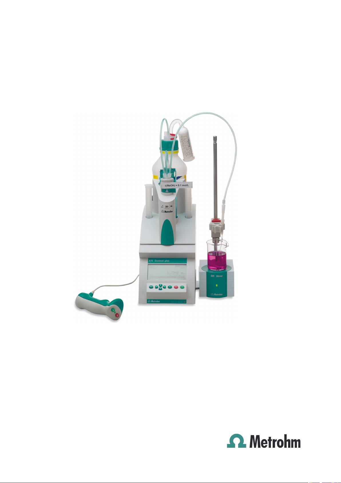
876 Dosimat plus
Manual
8.876.8003EN
Page 2

Page 3

Metrohm AG
CH-9100 Herisau
Switzerland
Phone +41 71 353 85 85
Fax +41 71 353 89 01
info@metrohm.com
www.metrohm.com
876 Dosimat plus
8.876.8003EN
Manual
09.2011 dm
Page 4

Teachware
Metrohm AG
CH-9100 Herisau
teachware@metrohm.com
This documentation is protected by copyright. All rights reserved.
Although all the information given in this documentation has been
checked with great care, errors cannot be entirely excluded. Should you
notice any mistakes please send us your comments using the address
given above.
Documentation in additional languages can be found on
http://products.metrohm.com under Literature/Technical documenta-
tion.
Page 5

■■■■■■■■■■■■■■■■■■■■■■
Table of contents
1 Introduction 1
1.1 Instrument description ......................................................... 1
1.1.1 Dosing modes ......................................................................... 1
1.1.2 Connectors .............................................................................. 1
1.2 Intended use ......................................................................... 2
1.3 About the documentation ................................................... 2
1.3.1 Symbols and conventions ........................................................ 2
1.4 Safety instructions ................................................................ 3
1.4.1 General notes on safety ........................................................... 3
1.4.2 Electrical safety ........................................................................ 3
1.4.3 Tubing connections ................................................................. 4
1.4.4 Flammable solvents and chemicals ........................................... 5
1.5 Recycling and disposal ......................................................... 5
Table of contents
2 Overview of the instrument 6
2.1 876 Dosimat plus ................................................................. 6
2.2 Manual Dosing Controller .................................................... 8
3 Installation 9
3.1 Setting up the instrument .................................................... 9
3.1.1 Packaging ................................................................................ 9
3.1.2 Checks .................................................................................... 9
3.1.3 Location .................................................................................. 9
3.2 Connecting a stirrer .............................................................. 9
3.3 Connecting the Manual Dosing Controller ....................... 10
3.4 Connecting a balance ......................................................... 10
3.5 Connecting a keyboard, printer and other USB devi-
ces ........................................................................................ 11
3.6 Connecting instruments to the remote connector .......... 13
3.7 Connecting the 805 Dosimat ............................................. 14
3.8 Attaching the exchange unit ............................................. 15
876 Dosimat plus
4 Operation 16
4.1 Switching the instrument on and off ............................... 16
4.2 Fundamentals of operation ............................................... 17
4.2.1 The keypad ............................................................................ 17
4.2.2 Structure of the dialog windows ............................................ 18
4.2.3 Navigating in the dialog ......................................................... 18
■■■■■■■■
III
Page 6

Table of contents
■■■■■■■■■■■■■■■■■■■■■■
4.2.4 Entering text and numbers ..................................................... 19
4.2.5 Selecting from a selection list ................................................. 20
4.3 Methods .............................................................................. 20
4.3.1 Method templates ................................................................. 20
4.3.2 Creating a new method ......................................................... 20
4.3.3 Saving a method ................................................................... 21
4.3.4 Loading a method ................................................................. 22
4.3.5 Exporting a method ............................................................... 23
4.4 Stirrer operation ................................................................. 24
4.5 Entering sample data ......................................................... 25
4.6 Preparing the buret unit (PREP) ........................................ 25
4.7 Printing a report manually ................................................. 26
5 System settings 28
5.1 Basic settings ...................................................................... 28
5.2 Managing solutions ............................................................ 31
5.2.1 General ................................................................................. 31
5.2.2 Editing the solution data ........................................................ 31
5.3 File management ................................................................ 33
5.4 Configuring external devices ............................................. 34
5.5 Instrument diagnosis .......................................................... 37
5.5.1 Loading program versions and language files ......................... 37
5.5.2 Diagnosis functions ............................................................... 38
6 Parameters and dosing modes 39
6.1 Manual dosing (DOS) ......................................................... 39
6.1.1 General description ................................................................ 39
6.1.2 Selecting a solution ............................................................... 40
6.1.3 Dosing parameters ................................................................ 40
6.1.4 Calculation ............................................................................ 41
6.1.5 Reports .................................................................................. 43
6.1.6 Pulse control .......................................................................... 43
6.2 Extended dosing (XDOS) .................................................... 44
6.2.1 General description ................................................................ 44
6.2.2 Selecting a solution ............................................................... 45
6.2.3 Selecting the operating mode ................................................ 45
6.2.4 Dosing parameters ................................................................ 47
6.2.5 Reports .................................................................................. 48
■■■■■■■■
IV
7 Handling and maintenance 49
7.1 General ................................................................................ 49
7.2 Quality Management and validation with Metrohm ....... 49
876 Dosimat plus
Page 7

■■■■■■■■■■■■■■■■■■■■■■
8 Appendix 51
Table of contents
8.1 Exchange unit ..................................................................... 51
8.1.1 Maximum dosing and filling rate ............................................ 51
8.1.2 Parameters for the preparing (PREP) ....................................... 51
8.2 Stirring rate ......................................................................... 52
8.3 Balance ................................................................................ 52
8.4 USB devices ......................................................................... 53
8.4.1 Numerical USB keypad 6.2147.000 ........................................ 53
8.4.2 Key assignment of a USB keyboard ........................................ 54
8.4.3 Printer ................................................................................... 54
8.5 System initialization ........................................................... 55
8.6 Remote interface ................................................................ 56
8.6.1 Pin assignment of the remote interface .................................. 56
8.6.2 Status diagram of the remote interface .................................. 57
8.7 Pulse control ....................................................................... 59
8.8 Remote control via an RS-232 connection ....................... 60
8.8.1 Commands and variables ....................................................... 61
9 Technical specifications 63
9.1 Dosing drive ........................................................................ 63
9.2 Interfaces ............................................................................. 63
9.3 Mains connection ............................................................... 63
9.4 Safety specification ............................................................ 64
9.5 Electromagnetic compatibility (EMC) ................................ 64
9.6 Ambient temperature ......................................................... 64
9.7 Reference conditions .......................................................... 65
9.8 Dimensions .......................................................................... 65
10 Conformity and warranty 66
10.1 Declaration of Conformity ................................................. 66
10.2 Quality Management Principles ........................................ 67
10.3 Warranty (Guarantee) ........................................................ 68
11 Accessories 70
11.1 Scope of delivery 2.876.0010 ............................................ 70
876 Dosimat plus
11.2 Scope of delivery 2.876.0010 ............................................ 72
11.3 Optional accessories ........................................................... 76
Index 79
■■■■■■■■
V
Page 8

Table of figures
Table of figures
Figure 1 Front 876 Dosimat plus ..................................................................... 6
Figure 2 Rear 876 Dosimat plus ...................................................................... 7
Figure 3 Manual Dosing Controller 6.2107.100 ............................................... 8
Figure 4 Connecting a stirrer ........................................................................... 9
Figure 5 Connecting the Manual Dosing Controller ....................................... 10
Figure 6 Connecting a balance ...................................................................... 10
Figure 7 Connecting USB devices .................................................................. 11
Figure 8 Connecting the USB stick ................................................................ 12
Figure 9 Connecting the 6.2147.000 USB keyboard with USB stick and
printer ............................................................................................. 13
Figure 10 Connecting the USB hub with USB stick, printer and the 6.2148.030
RS-232/USB Box (for connecting balances). ...................................... 13
Figure 11 Connecting a remote cable ............................................................. 13
Figure 12 Connecting the 805 Dosimat ........................................................... 14
Figure 13 MSB connector on the 801 Stirrer ................................................... 14
Figure 14 Attaching the exchange unit ........................................................... 15
Figure 15 Keypad 876 Dosimat plus ................................................................ 17
Figure 16 Directory structure on the USB stick ................................................. 34
Figure 17 Dosing ramp, two examples ............................................................ 41
Figure 18 Tandem operation ........................................................................... 46
Figure 19 Rotational speed depending on stirring rate .................................... 52
Figure 20 Pin assignment of remote socket and plug ...................................... 56
Figure 21 Remote status diagram DOS ............................................................ 57
Figure 22 Remote status diagram DOS with pulse control ............................... 58
Figure 23 Remote status diagram XDOS .......................................................... 58
Figure 24 Connecting the RS-232/USB Box to the PC ...................................... 60
■■■■■■■■■■■■■■■■■■■■■■
■■■■■■■■
VI
876 Dosimat plus
Page 9

■■■■■■■■■■■■■■■■■■■■■■
1 Introduction
1.1 Instrument description
The 876 Dosimat plus is a universally utilizable dosing instrument. Methods can be generated and stored under a new name. When a USB memory stick is connected as an external storage medium, then the methods
can be exported to that USB memory stick. This function makes it possible
for you to copy methods quickly and easily from one instrument to
another. The remote connector enables the integration of the instrument
in a Metrohm automation system.
1.1.1 Dosing modes
The following dosing modes are supported:
■ DOS
Manual dosing.
■ XDOS
Fixed volume dosing, with freely selectable dosing criteria.
1 Introduction
1.1.2 Connectors
The instrument is equipped with the following connectors:
■ MSB connector (Metrohm Serial Bus)
■ USB (OTG) connector
■ Remote connector
For connecting a stirrer and an 805 Dosimat for tandem dosings.
The 6.2151.100 adapter allows you to connect, for example, a printer,
a USB memory stick or a USB keyboard. A printer can also be connected directly with the 6.2151.120 cable.
For connecting a Manual Dosing Controller, a Titrino plus or a sample
changer.
876 Dosimat plus
■■■■■■■■
1
Page 10
1.2 Intended use
1.2 Intended use
The 876 Dosimat plus is designed for use in laboratories and production
plants. Its main area of application is the precise dosing of liquids. This
includes simple dosing according to specific criteria and manual titrations.
The present instrument is suitable for dosing chemicals and flammable solvents. The usage of the 876 Dosimat plus therefore requires that the user
has basic knowledge and experience in the handling of poisonous and
caustic substances. Knowledge with respect to the application of the fire
prevention measures prescribed for laboratories or production plants is
also mandatory.
1.3 About the documentation
Caution
■■■■■■■■■■■■■■■■■■■■■■
Please read through this documentation carefully before putting the
instrument into operation. The documentation contains information
and warnings which have to be followed by the user in order to ensure
safe operation of the instrument.
1.3.1 Symbols and conventions
The following symbols and styles are used in this documentation:
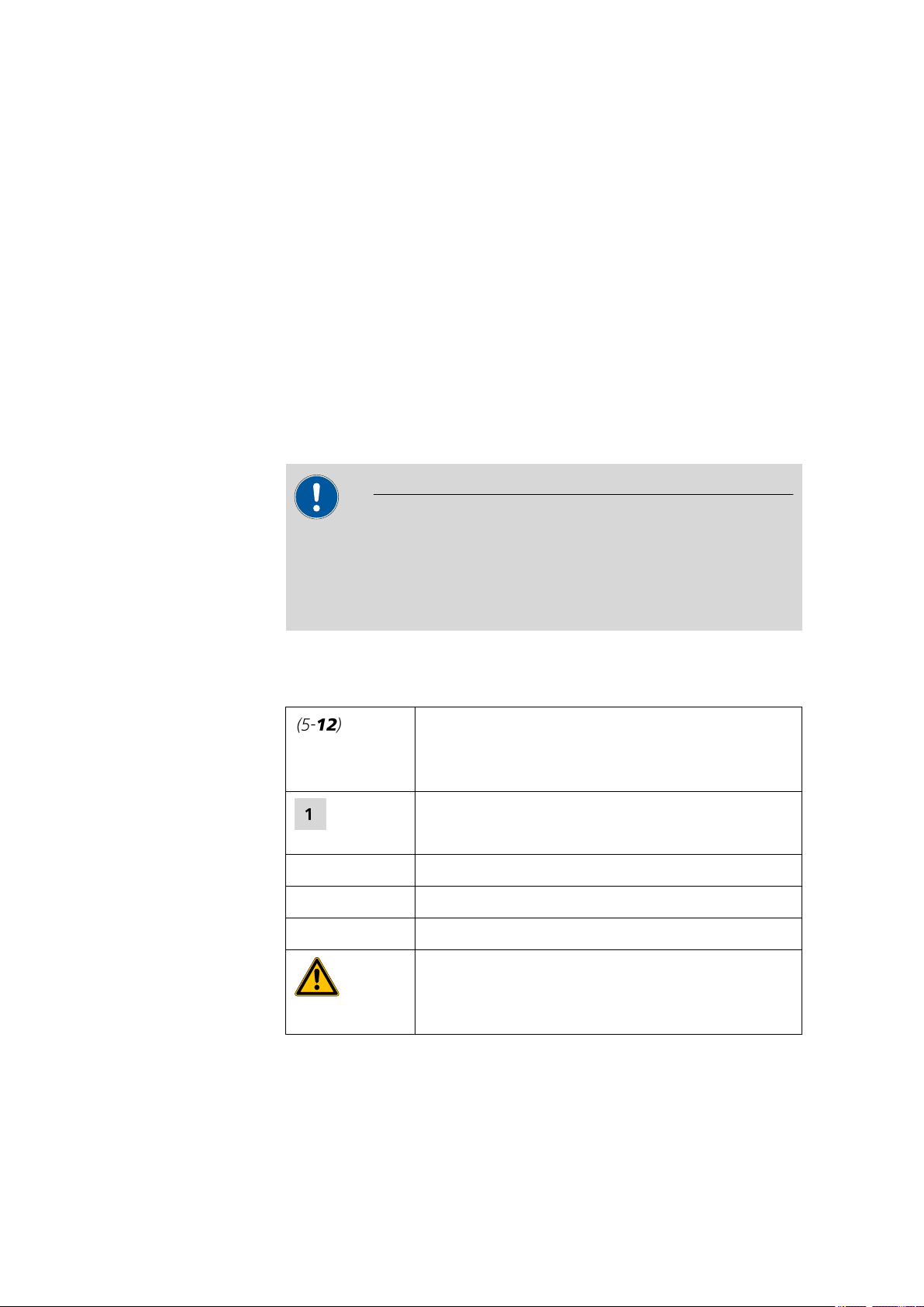
Method Dialog text, parameter in the software
File ▶ New Menu or menu item
[Next] Button or key
Cross-reference to figure legend
The first number refers to the figure number, the
second to the instrument part in the figure.
Instruction step
Carry out these steps in the sequence shown.
Warning
■■■■■■■■
2
This symbol draws attention to a possible life hazard
or risk of injury.
876 Dosimat plus
Page 11
■■■■■■■■■■■■■■■■■■■■■■
1 Introduction
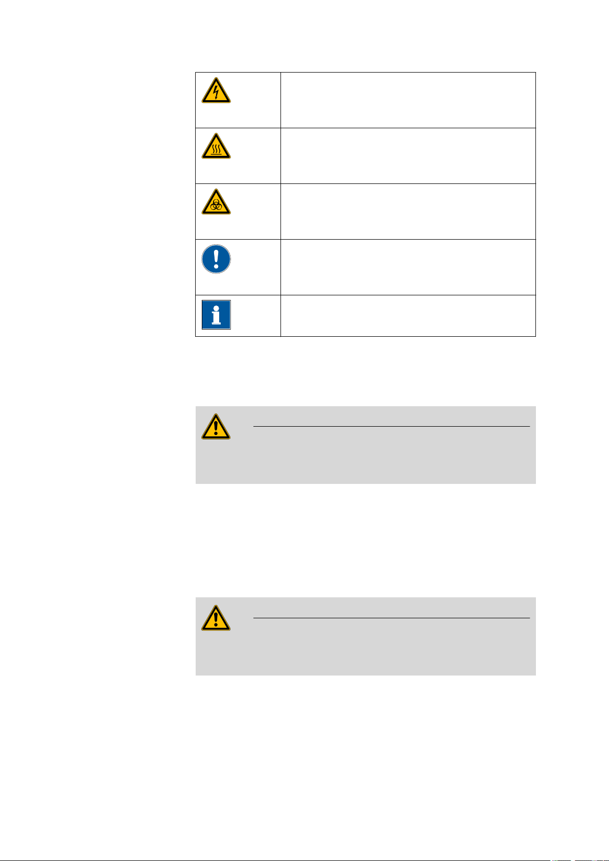
Warning
This symbol draws attention to a possible hazard due
to electrical current.
Warning
This symbol draws attention to a possible hazard due
to heat or hot instrument parts.
Warning
This symbol draws attention to a possible biological
hazard.
Caution
This symbol draws attention to a possible damage of
instruments or instrument parts.
Note
This symbol marks additional information and tips.
1.4 Safety instructions
1.4.1 General notes on safety
Warning
This instrument may only be operated in accordance with the specifications in this documentation.
This instrument has left the factory in a flawless state in terms of technical
safety. To maintain this state and ensure non-hazardous operation of the
instrument, the following instructions must be observed carefully.
1.4.2 Electrical safety
The electrical safety when working with the instrument is ensured as part
of the international standard IEC 61010.
Warning
Only personnel qualified by Metrohm are authorized to carry out service
work on electronic components.
876 Dosimat plus
■■■■■■■■
3
Page 12
1.4 Safety instructions
■■■■■■■■■■■■■■■■■■■■■■
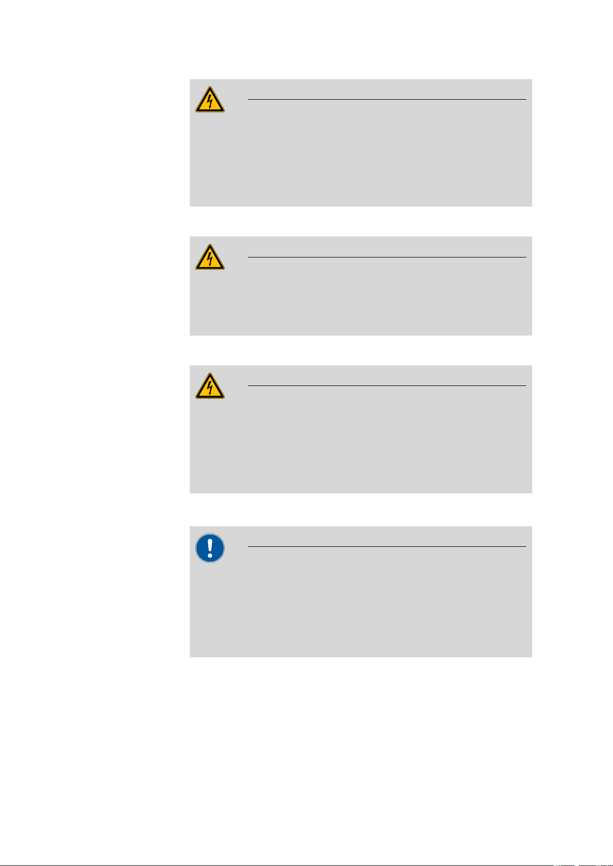
Warning
Never open the housing of the instrument. The instrument could be
damaged by this. There is also a risk of serious injury if live components
are touched.
There are no parts inside the housing which can be serviced or replaced
by the user.
Mains voltage
Warning
An incorrect mains voltage can damage the instrument.
Only operate this instrument with a mains voltage specified for it (see
rear panel of the instrument).
Protection against electrostatic charges
Electronic components are sensitive to electrostatic charges and can be
destroyed by discharges.
Always pull the mains cable out of the mains connection socket before
connecting or disconnecting electrical appliances on the rear panel of
the instrument.
1.4.3 Tubing connections
Leaks in tubing connections are a safety risk. Tighten all connections
well by hand. Avoid applying excessive force to tubing connections.
Damaged tubing ends lead to leakage. Appropriate tools can be used
to loosen connections.
Check the connections regularly for leaks.
Warning
Caution
■■■■■■■■
4
876 Dosimat plus
Page 13
■■■■■■■■■■■■■■■■■■■■■■
1.4.4 Flammable solvents and chemicals
Warning
All relevant safety measures are to be observed when working with
flammable solvents and chemicals.
■ Set up the instrument in a well-ventilated location.
■ Keep all sources of flame far from the workplace.
■ Clean up spilled fluids and solids immediately.
■ Follow the safety instructions of the chemical manufacturer.
1.5 Recycling and disposal
This product is covered by European Directive 2002/96/EC, WEEE – Waste
from Electrical and Electronic Equipment.
The correct disposal of your old equipment will help to prevent negative
effects on the environment and public health.
1 Introduction
More details about the disposal of your old equipment can be obtained
from your local authorities, from waste disposal companies or from your
local dealer.
876 Dosimat plus
■■■■■■■■
5
Page 14
2.1 876 Dosimat plus
2
5
4
3
1
2 Overview of the instrument
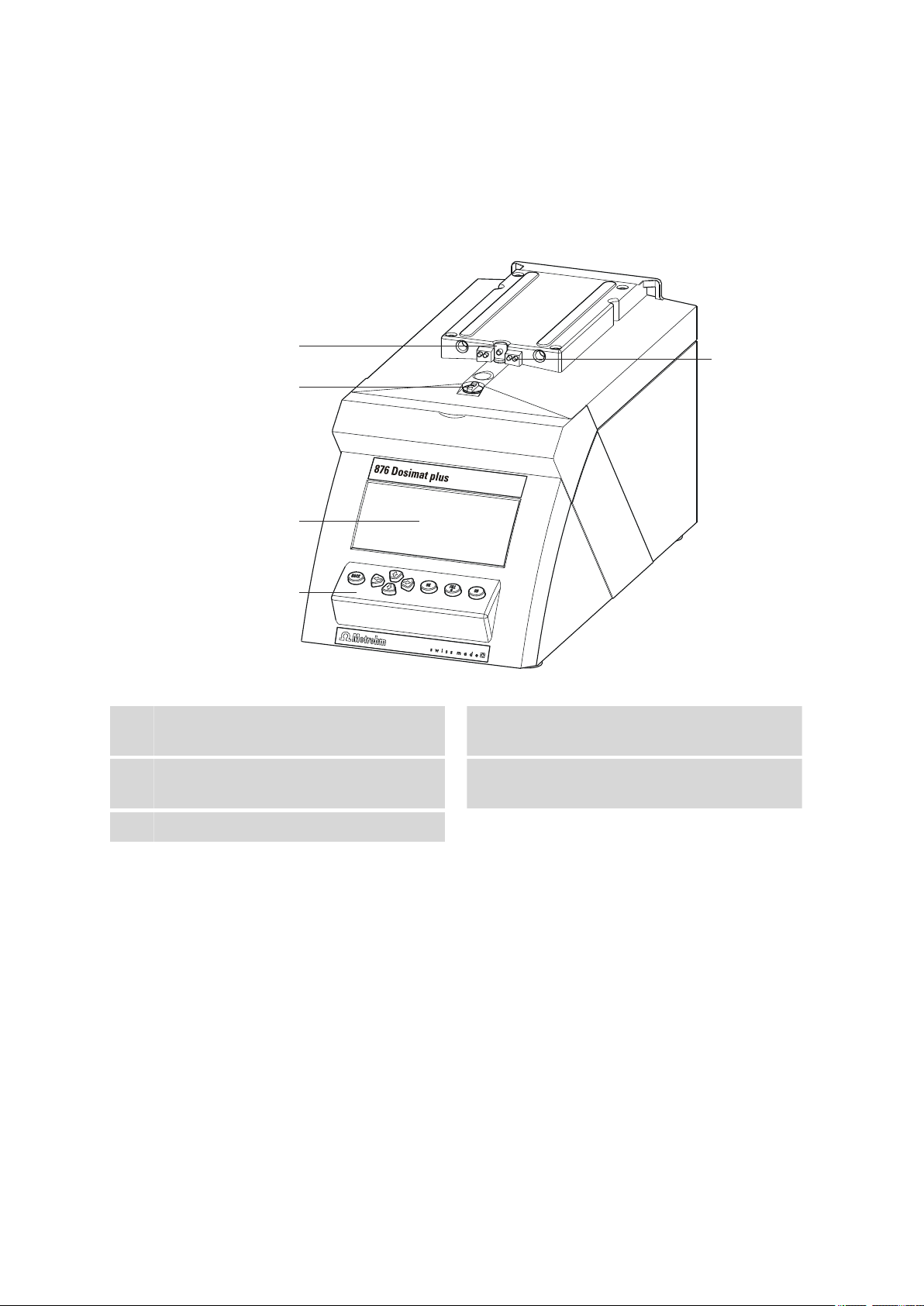
2.1 876 Dosimat plus
■■■■■■■■■■■■■■■■■■■■■■
Figure 1 Front 876 Dosimat plus
Piston rod
1
Of the dosing drive.
Coupling
3
For switching the flat stopcock.
Keypad
5
Contact pins
2
For the data chip.
Display
4
■■■■■■■■
6
876 Dosimat plus
Page 15
■■■■■■■■■■■■■■■■■■■■■■
1
2
5
4
3
2 Overview of the instrument
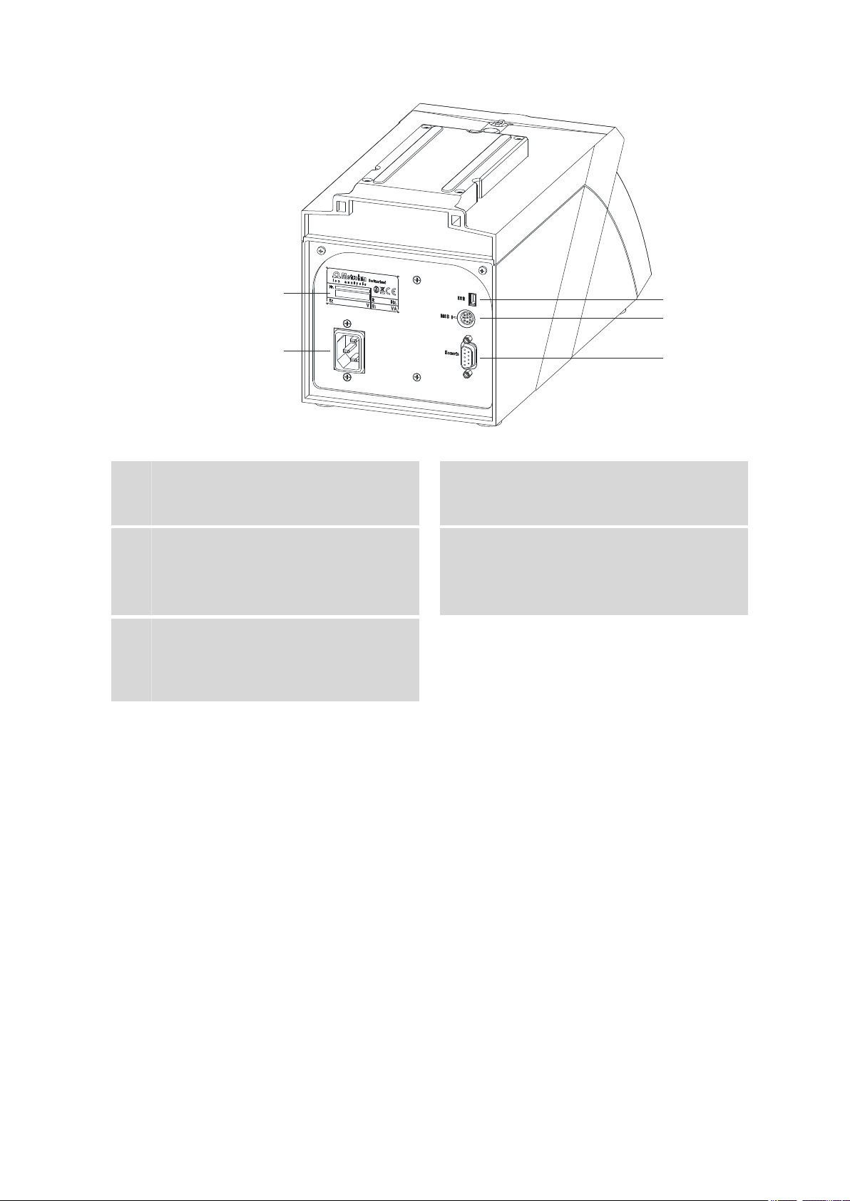
Figure 2 Rear 876 Dosimat plus
Type plate
1
Contains specifications concerning mains
voltage and serial number.
USB (OTG) connector
3
For connecting printers, USB sticks, USB
hubs, etc.
Remote connector
5
For connecting the Manual Dosing Controller or instruments with a remote interface.
D-Sub, 9-pin.
Mains connection socket
2
MSB connector
4
Metrohm Serial Bus.
For connecting a stirrer or an 805 Dosimat.
Mini DIN, 9-pin.
876 Dosimat plus
■■■■■■■■
7
Page 16
2.2 Manual Dosing Controller
1
2
3
4
2.2 Manual Dosing Controller
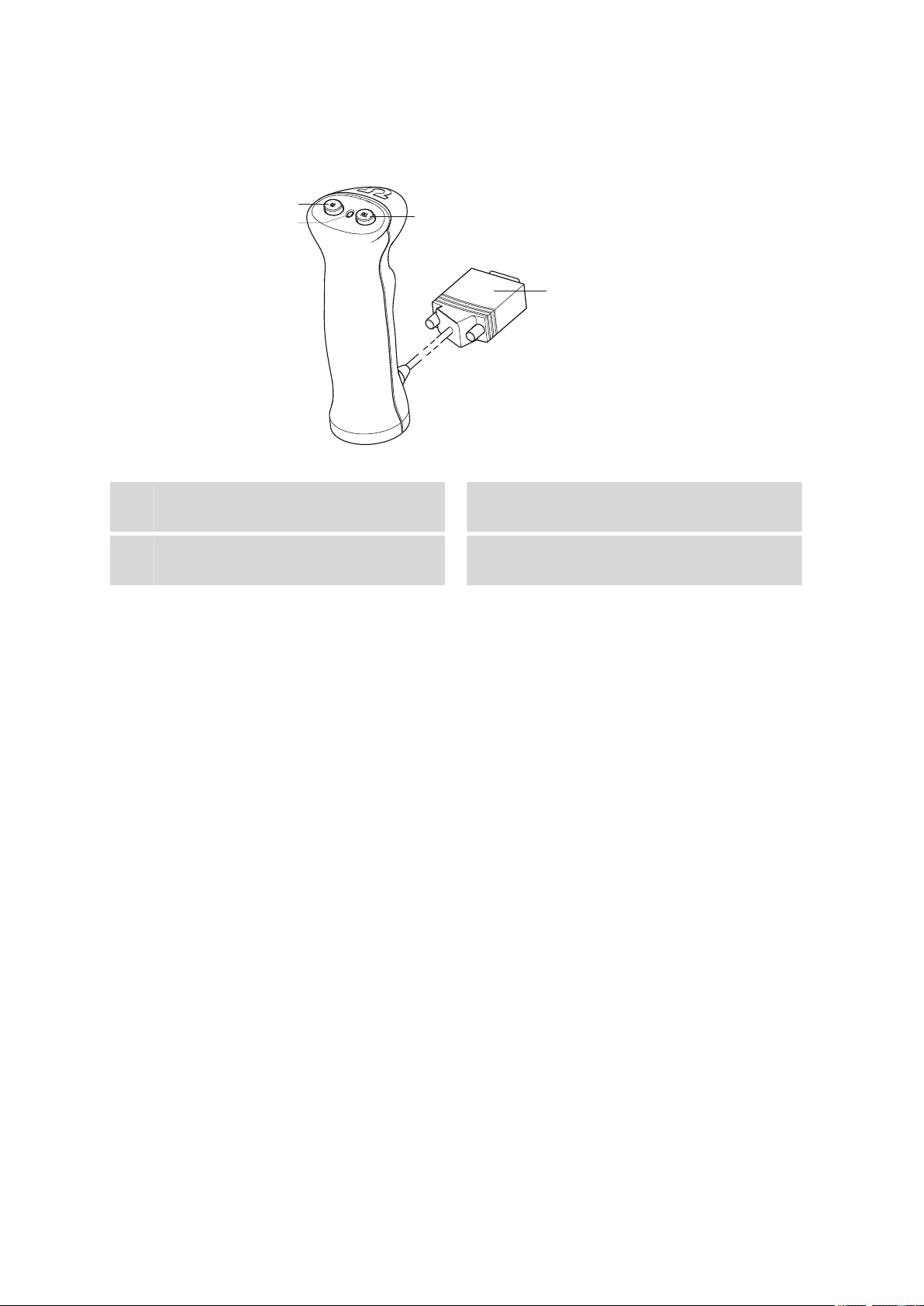
Figure 3 Manual Dosing Controller 6.2107.100
■■■■■■■■■■■■■■■■■■■■■■
Dosing key
1
To start the dosing.
Stop key/Fill key
3
For stopping and filling the dosing cylinder.
Status LED
2
Indicates the readiness of the instrument.
Connection cable
4
With 9-pin D-Sub plug.
■■■■■■■■
8
876 Dosimat plus
Page 17
■■■■■■■■■■■■■■■■■■■■■■
3 Installation
3.1 Setting up the instrument
3.1.1 Packaging
The instrument is supplied in highly protective special packaging together
with the separately packed accessories. Keep this packaging, as only this
ensures safe transportation of the instrument.
3.1.2 Checks
Immediately after receipt, check whether the shipment has arrived complete and without damage by comparing it with the delivery note.
3.1.3 Location
The instrument has been developed for operation indoors and may not be
used in explosive environments.
3 Installation
Place the instrument in a location of the laboratory which is suitable for
operation, free of vibrations, protected from corrosive atmosphere, and
contamination by chemicals.
The instrument should be protected against excessive temperature fluctuations and direct sunlight.
3.2 Connecting a stirrer
You can connect the following stirrers:
■ 801 Stirrer
■ 803 Ti Stand
■ 804 Ti Stand (requires rod stirrer)
876 Dosimat plus
Figure 4
Connecting a stirrer
■■■■■■■■
9
Page 18
3.3 Connecting the Manual Dosing Controller
Caution
Make sure that the flat side of the plug matches the marking on the
socket.
■■■■■■■■■■■■■■■■■■■■■■
3.3 Connecting the Manual Dosing Controller
Figure 5 Connecting the Manual Dosing Controller
The Manual Dosing Controller is connected to the remote connector on
the rear of the instrument.
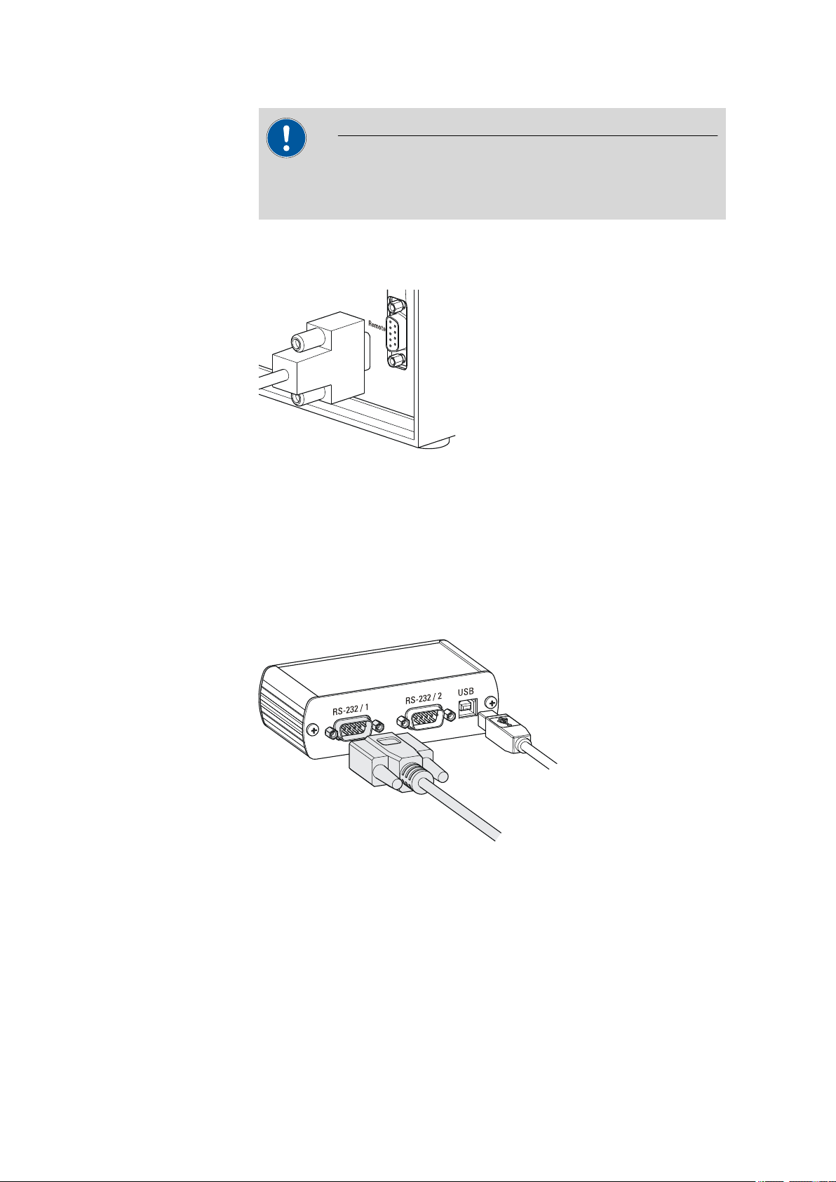
3.4 Connecting a balance
Balances are equipped with a serial RS-232 interface as a rule. To connect
a balance, you require a 6.2148.030 RS-232/USB Box.
Figure 6
When a 6.2151.020 USB cable is used, then the 6.2148.030 RS-232/USB
Box can be connected to the 876 Dosimat plus by means of a USB hub or
a 6.2151.100 adapter (see Chapter 3.5, page 11).
Connecting a balance
■■■■■■■■
10
Connect the 9-pin plug of the respective balance connecting cable to the
RS 232/1 connector. Consult the user manual of the balance in order to
select the correct connecting cable.
876 Dosimat plus
Page 19
■■■■■■■■■■■■■■■■■■■■■■
6.2151.100
3 Installation
The parameters for the RS-232 interface on the instrument must match
those on the balance (see "Editing the COM1 settings", page 35). Additionally consult the user manual of the balance.
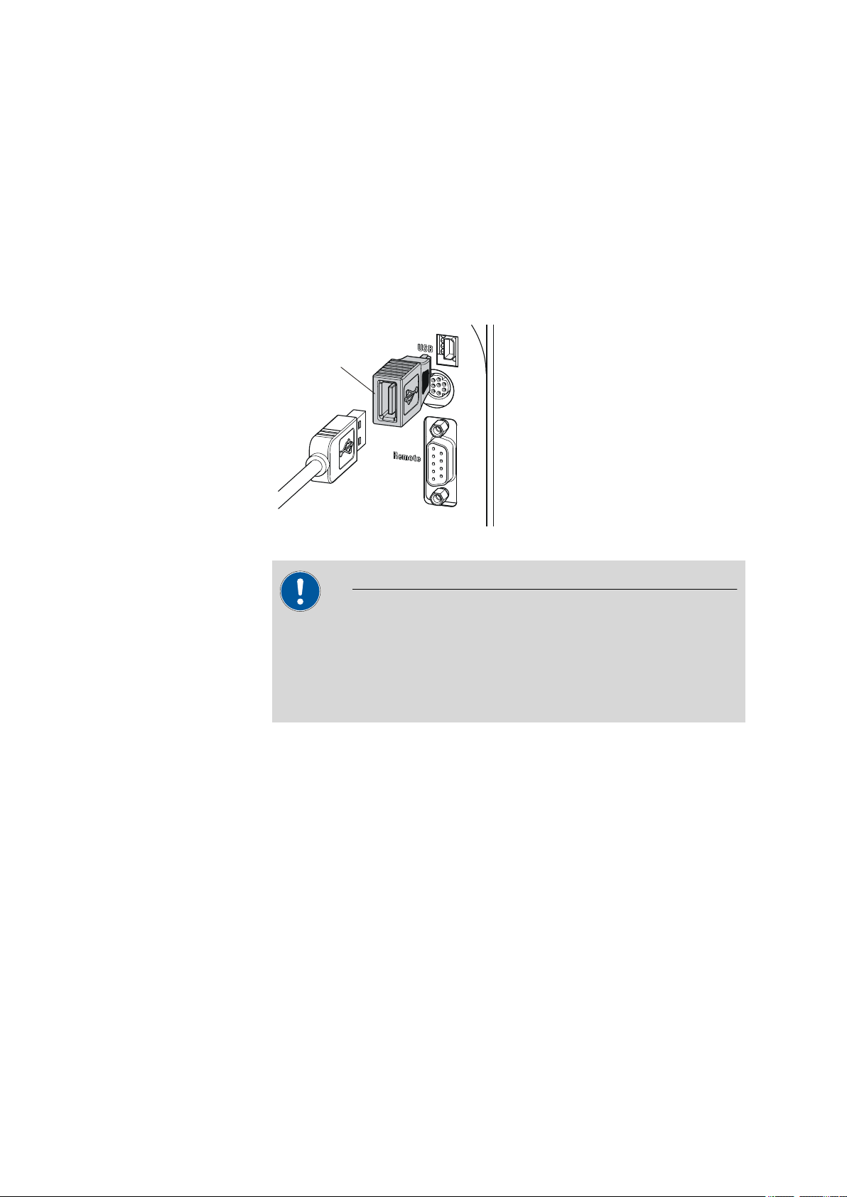
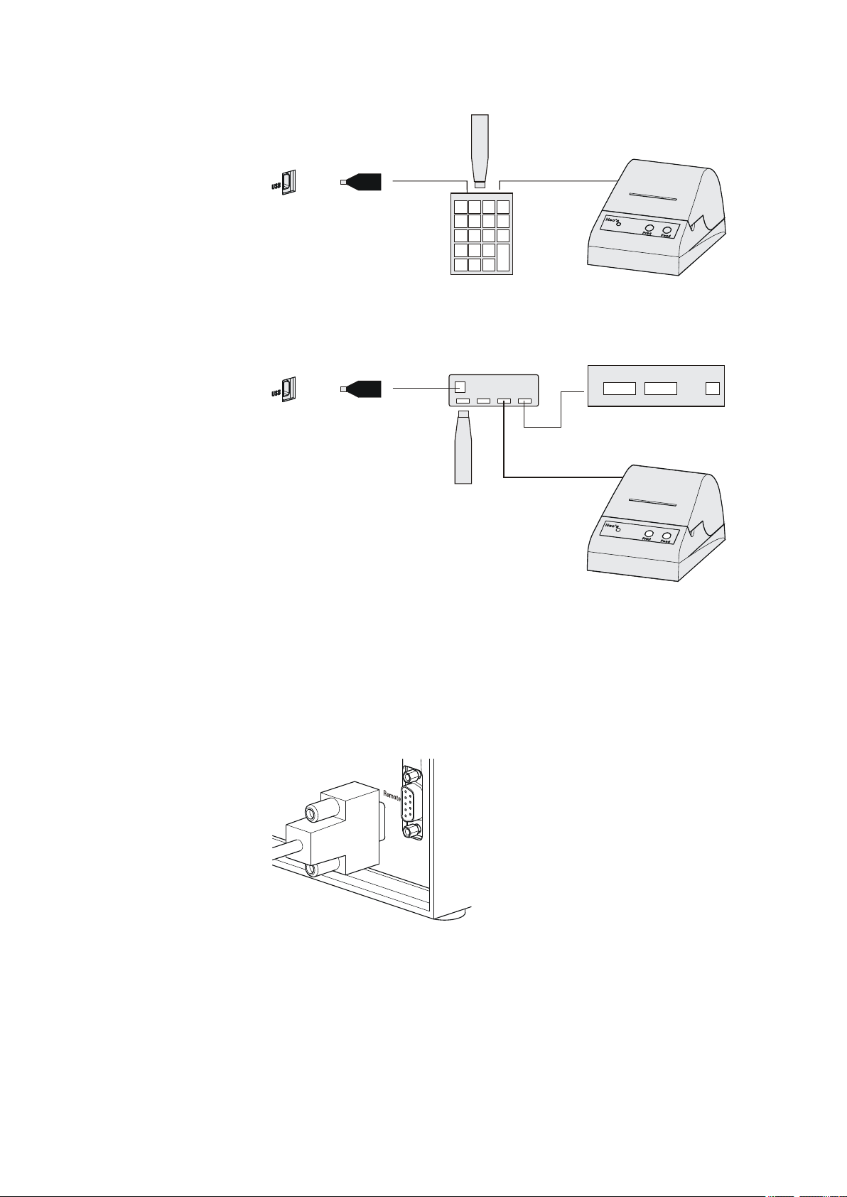
3.5 Connecting a keyboard, printer and other USB devices
The 876 Dosimat plus has a USB (OTG) connector. Use the provided
6.2151.100 adapter USB MINI (OTG) - USB A for connecting USB devices
as e.g. printers, keyboards or USB sticks, see the following figure.
Figure 7
Connecting USB devices
Caution
Switch the instrument off before connecting or disconnecting a USB
device or a USB stick.
The 876 Dosimat plus can only recognize the device immediately after
switching on.
The following devices can be operated directly on the USB connector
with the 6.2151.100 adapter:
■ USB sticks (for the backup or storing of methods)
■ 6.2147.000 numerical USB keypad
■ 6.2148.030 RS-232/USB Box (for connecting balances or for the
RS-232 remote control)
■ USB hub (with or without an own power supply)
The 6.2147.000 numerical USB keypad serves for comfortable numerical input and for navigating in the dialog. In addition, it provides two USB
connectors. Connect additional USB devices to the keypad.
876 Dosimat plus
■■■■■■■■
11
Page 20
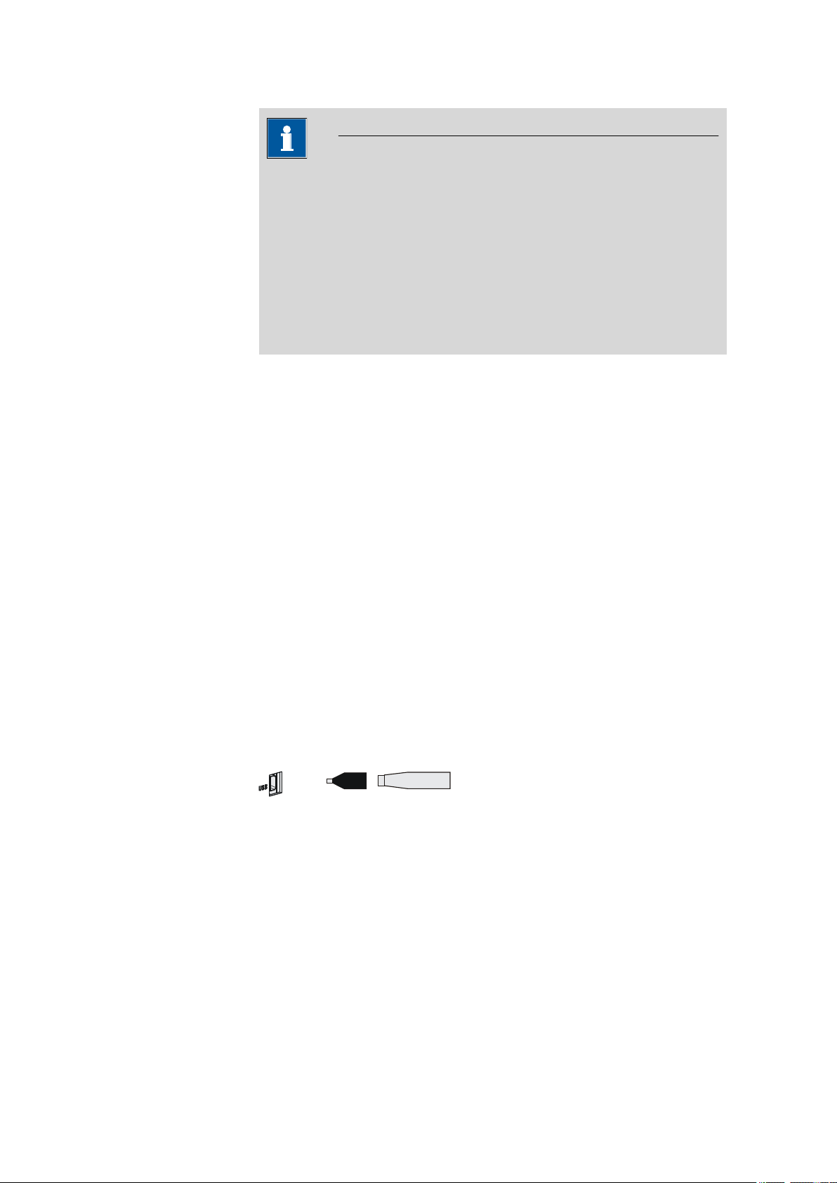
3.5 Connecting a keyboard, printer and other USB devices
USB MINI (OTG)-USB
USB stick
6.2151.100
Note
Most of the USB devices need a so-called hub in order to work correctly.
A USB hub is a distributor to which several USB devices can be connected. USB hubs are available in specialty stores in a number of different
models.
The USB (OTG) connector of the 876 Dosimat plus has no such hub.
The 6.2147.000 numerical USB keypad has a USB hub and two USB
connectors.
The following devices can only be connected to a 6.2147.000
numerical keypad or to a USB hub:
■ Printer (with USB connector, use the 6.2151.020 connecting cable)
■ Barcode reader (with USB cable)
■ Mouse (PC mouse with USB cable, for navigating in the dialog)
■■■■■■■■■■■■■■■■■■■■■■
The following devices can only be connected to a USB hub:
■ PC keyboard (with USB cable, for the comfortable input of letters and
numbers)
■ Keypad with numerical keypad (with USB cable)
If you wish to connect several different instruments without own
power supply, then you must possibly use a USB hub with own power
supply (self powered). The USB (OTG) connector of the 876 Dosimat plus
is not designed for supplying power to several devices with elevated electricity requirements.
Also observe the instructions in chapter 8.4, page 53.
Examples:
Figure 8
Connecting the USB stick
■■■■■■■■
12
876 Dosimat plus
Page 21
■■■■■■■■■■■■■■■■■■■■■■
USB MINI (OTG)-USB
USB stick
Keypad
6.2147.000
6.2151.100
Printer
USB MINI (OTG)-USB
USB stick
USB-Hub
RS-232/USB Box
6.2148.030
6.2151.100
Printer
3 Installation
Figure 9 Connecting the 6.2147.000 USB keyboard with USB stick and
printer
3.6 Connecting instruments to the remote connector
Figure 10 Connecting the USB hub with USB stick, printer and the
6.2148.030 RS-232/USB Box (for connecting balances).
The 876 Dosimat plus can be integrated in an automation system with the
aid of a remote cable.
Figure 11
A variety of different connecting cables are available for connecting
Metrohm instruments (e.g. sample changers) (see Optional Accessories
Connecting a remote cable
chapter).
876 Dosimat plus
■■■■■■■■
13
Page 22
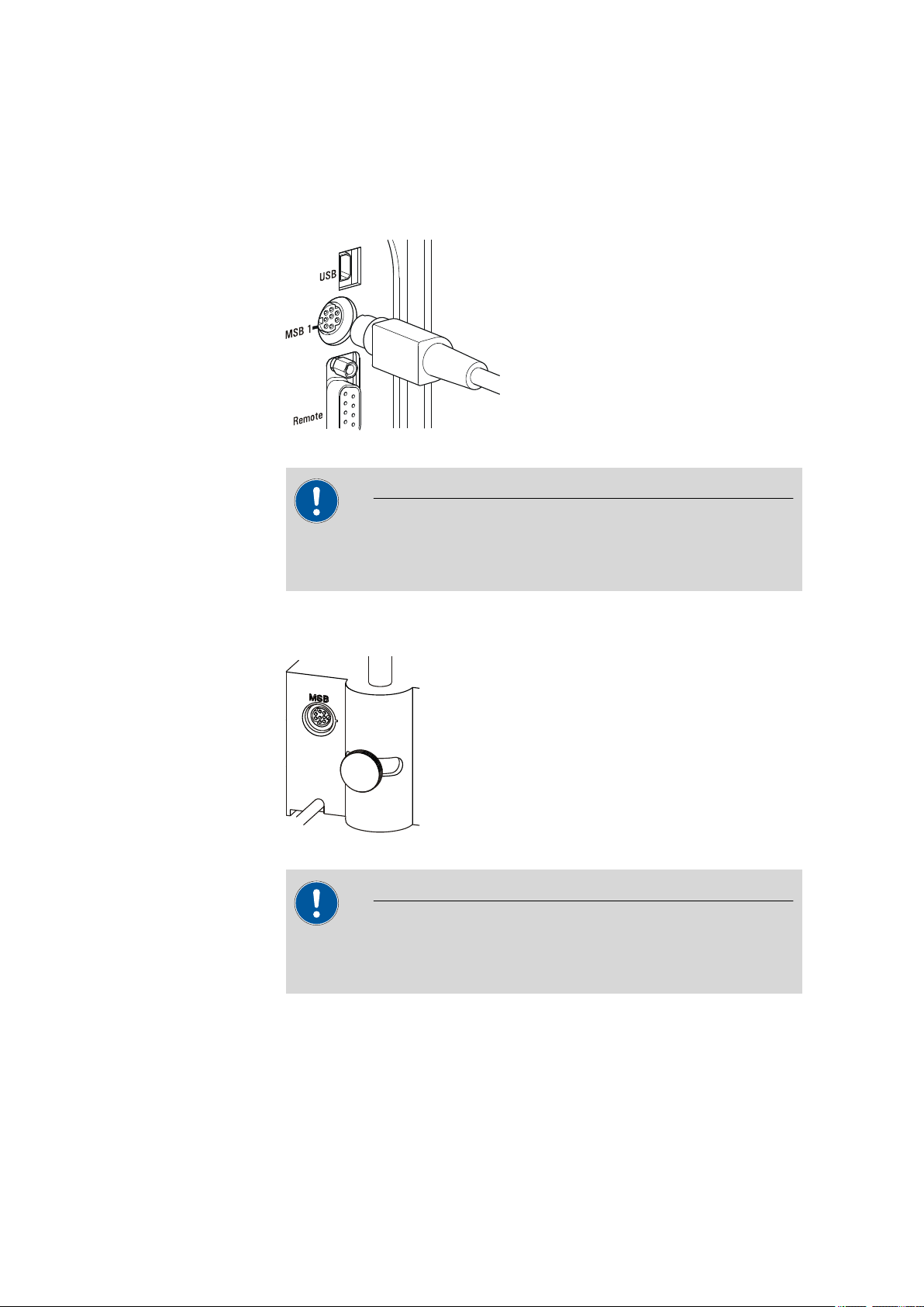
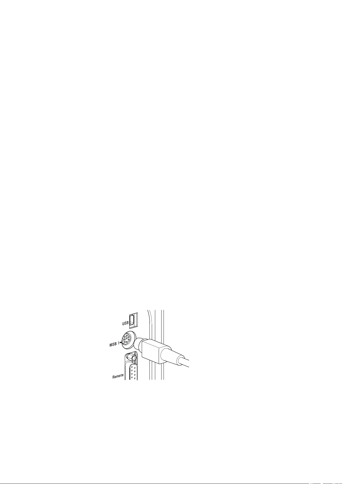
3.7 Connecting the 805 Dosimat
3.7 Connecting the 805 Dosimat
For tandem operation (XDOS mode), an 805 Dosimat can be connected to
the MSB 1 socket on the rear of the 876 Dosimat plus.
Figure 12 Connecting the 805 Dosimat
Caution
■■■■■■■■■■■■■■■■■■■■■■
Make sure that the flat side of the plug matches the marking on the
socket.
If the MSB 1 connector is already occupied by a stirrer (e.g. 801 Stirrer),
then the 805 Dosimat can be connected to the MSB socket of the stirrer.
Figure 13
MSB connector on the 801 Stirrer
Caution
Make sure that the flat side of the plug matches the marking on the
socket.
■■■■■■■■
14
The 876 Dosimat plus must be switched off and then on again after connection.
876 Dosimat plus
Page 23
■■■■■■■■■■■■■■■■■■■■■■
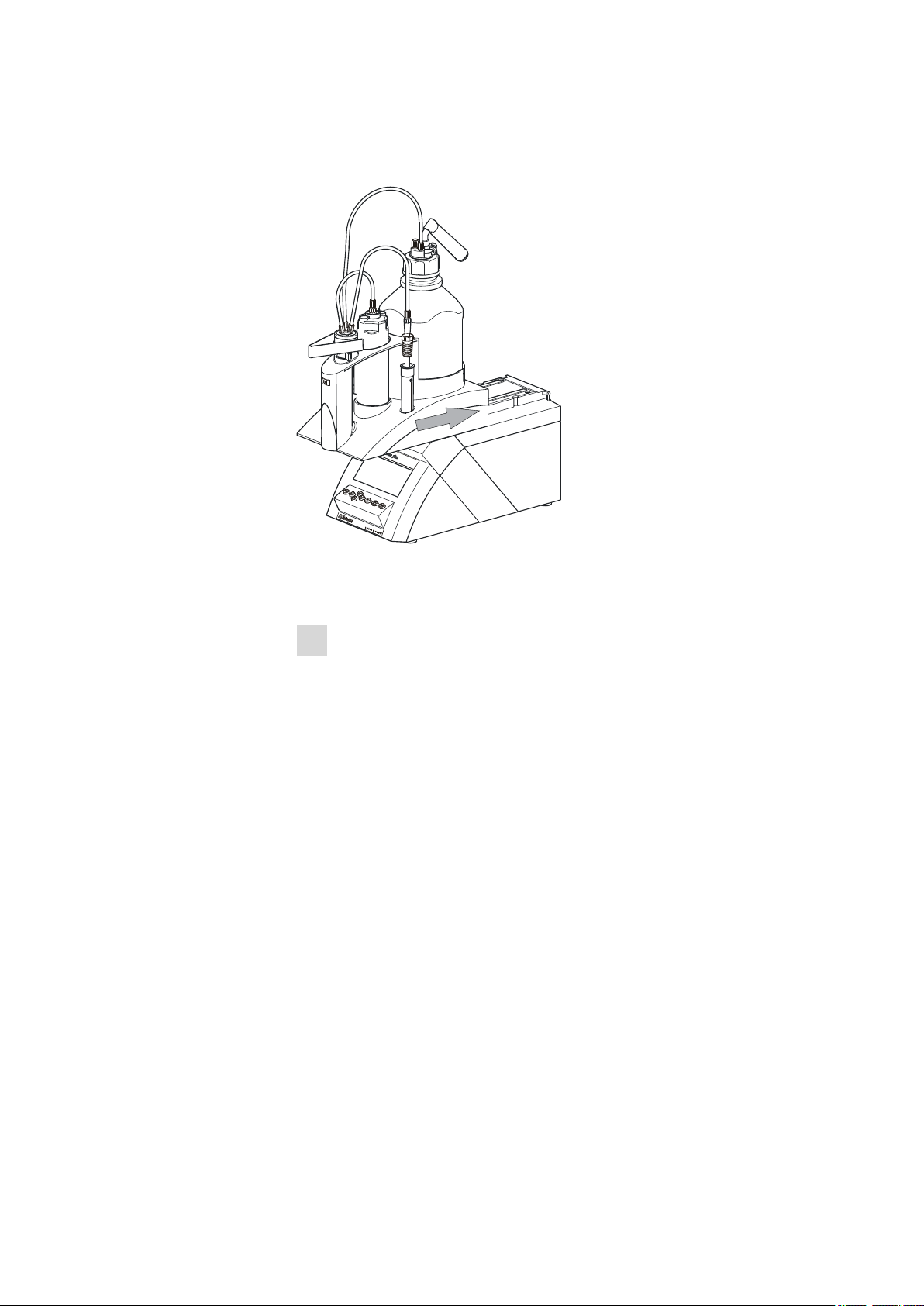
3.8 Attaching the exchange unit
3 Installation
Figure 14 Attaching the exchange unit
To attach the exchange unit, proceed as follows:
Slide the exchange unit from the front onto the 876 Dosimat plus
1
and push all the way to the rear.
It must snap in audibly.
876 Dosimat plus
■■■■■■■■
15
Page 24
4.1 Switching the instrument on and off
4 Operation
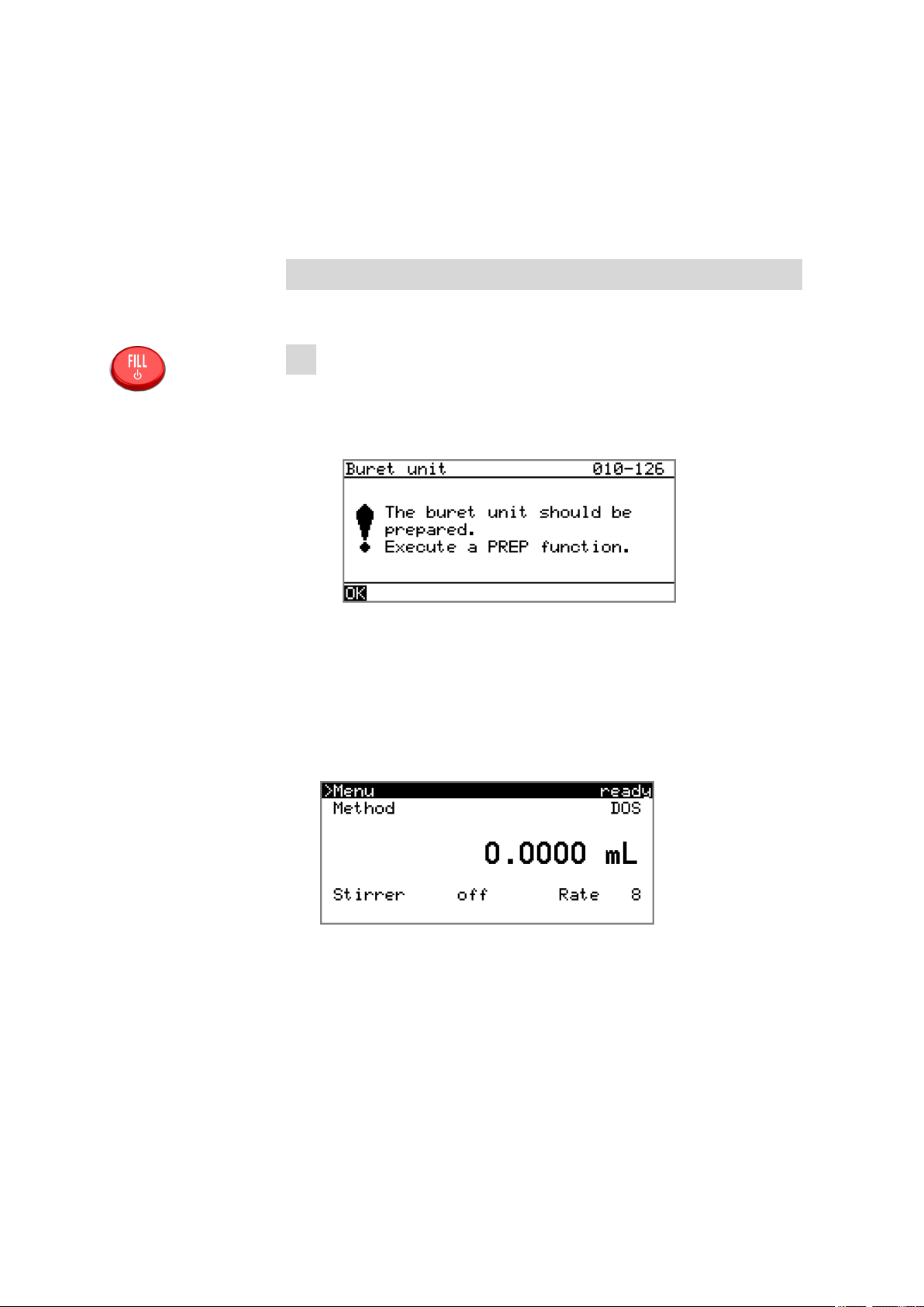
4.1 Switching the instrument on and off
Switching on the instrument
Proceed as follows:
■ Press the red [FILL] key.
1
The instrument is initialized and a system test performed. This
process takes some time.
■ If a buret unit has been attached, then a request appears to carry
out the PREP function:
■■■■■■■■■■■■■■■■■■■■■■
All tubings and the cylinder are rinsed with the PREP (Preparing)
function. The preparing of the buret unit is described in chapter
"Preparing the buret unit (PREP)", page 25.
■ Confirm the message with [OK].
The display of this message can be deactivated in the system settings (see "PREP warning", page 30).
The main dialog is displayed:
■■■■■■■■
16
876 Dosimat plus
Page 25
■■■■■■■■■■■■■■■■■■■■■■
FILL
GO
Switching off the instrument
The instrument is switched off with the [FILL] key. The fact that the key
needs to be pressed down for an extended time prevents accidental
switch off.
Proceed as follows:
■ Keep the red [FILL] key pressed down for at least 3 s.
1
A progress bar is displayed. If the key is released during this time,
then the instrument will not be switched off.
4.2 Fundamentals of operation
4.2.1 The keypad
4 Operation
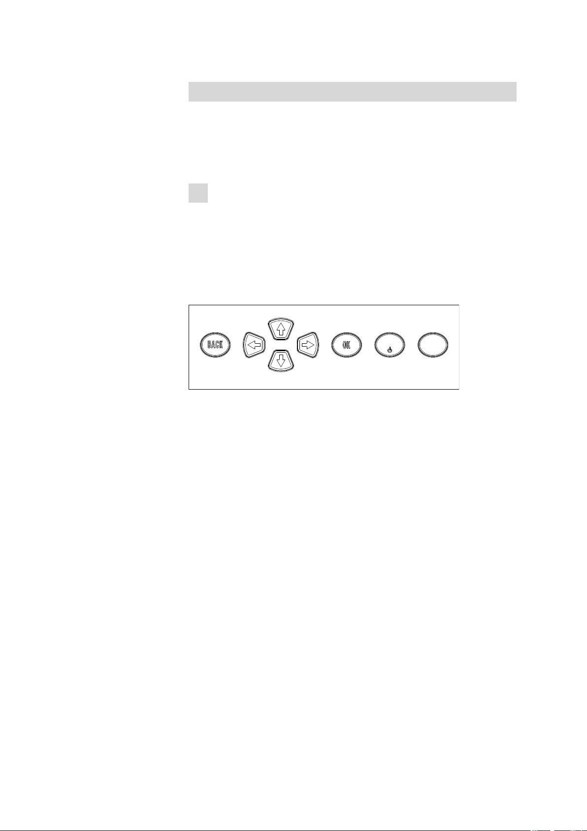
Figure 15
Keypad 876 Dosimat plus
BACK Apply the input and exit the dialog.
⇧ ⇩ Move the selection bar either up or down by one
line at a time. Select the character to be entered
in the text editor.
⇦ ⇨ Select the character to be entered in the text and
number editor. Select the individual functions in
the function bar.
OK Confirm the selection.
FILL Stop an ongoing method run or a manual func-
tion. Switch the instrument on/off.
GO Start a method run or a manual function.
876 Dosimat plus
■■■■■■■■
17
Page 26
4.2 Fundamentals of operation
4.2.2 Structure of the dialog windows
The current dialog title is displayed on the left-hand side of the title line.
The current status of the system is displayed in the upper right-hand corner:
ready The instrument is in normal status.
busy A method has been started.
hold A method has been paused.
Some dialogs have a so-called function bar on the bottom line. The functions contained therein can be selected with the arrow keys [⇦] or [⇨]
and executed with [OK].
■■■■■■■■■■■■■■■■■■■■■■
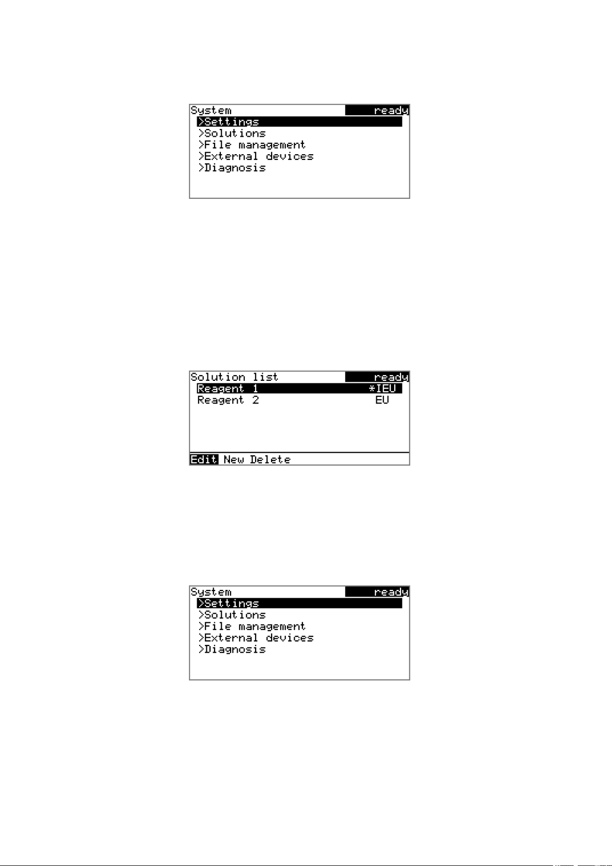
4.2.3 Navigating in the dialog
The selection bar is displayed in inverted style. Use the arrow keys [⇧] and
[⇩] to move the selection bar upward or downward one line at a time. If
a dialog text is marked with ">", then additional settings are available in
a subordinate dialog. Use [OK] to access this dialog.
Example: System settings
Use the [BACK] key to return to the next higher level.
■■■■■■■■
18
876 Dosimat plus
Page 27
■■■■■■■■■■■■■■■■■■■■■■
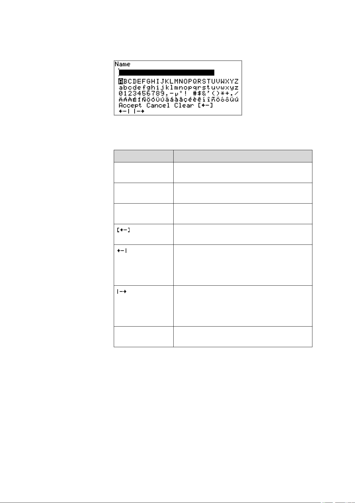
4.2.4 Entering text and numbers
In the editing dialog for text or numerical input you can select the individual characters with the arrow keys. Use [OK] to apply the character in the
input field. The following functions are available:
4 Operation
Editing function
Description
Accept The modification is applied and the editing dialog
is exited.
Cancel The editing dialog is exited without applying the
modification.
Clear The content of the input field is deleted com-
pletely.
The character left of the cursor is deleted (backspace).
Text editor only
The cursor within the input field is shifted to the
left by one character each time that [OK] is
pressed.
Text editor only
The cursor within the input field is shifted to the
right by one character each time that [OK] is
pressed.
876 Dosimat plus
[BACK] The modification is applied and the editing dialog
is exited.
The [BACK] key has the same function as Accept.
A commercially available USB keyboard can be connected to make it easier to enter text and numbers. The key assignment on the PC keyboard is
described in chapter 8.4.2, page 54.
■■■■■■■■
19
Page 28

4.3 Methods
4.2.5 Selecting from a selection list
In a selection list, select the individual entries with the arrow keys [⇧] and
[⇩]. Accept the selection with [OK] or [BACK].
4.3 Methods
4.3.1 Method templates
The 876 Dosimat plus contains method templates which are already configured and which can be adjusted to individual requirements.
The following method templates can be selected:
■■■■■■■■■■■■■■■■■■■■■■
DOS Manual interactive dosing with optional calculat-
XDOS Automatic dosing with freely selectable specifi-
You will find a detailed description of the methods in chapter .
4.3.2 Creating a new method
Proceed as follows to create a new method:
1
Open the method table
■ In the main dialog, select Method and press [OK].
The method table opens:
ing results.
For manual titrations.
cations.
The following specifications are possible:
■ Volume and time
■ Volume and dosing rate
■ Dosing rate and time
■■■■■■■■
20
876 Dosimat plus
Page 29

■■■■■■■■■■■■■■■■■■■■■■
2
Select the method template
■ In the function bar, select New and press [OK].
The list of method templates opens:
4 Operation
3
Load the method template
■ Select the desired template and press [OK].
The method template is now loaded and is displayed in the main dialog under Method.
If a new method has been created, then the individual parameters can be
modified under Menu ▶ Parameters.
4.3.3 Saving a method
If you modify method parameters, then you can save these as your own
method. A maximum of 100 methods can be saved.
To save a method, proceed as follows:
1
Open the method table
■ In the main dialog, select Method and press [OK].
The method table opens:
876 Dosimat plus
■■■■■■■■
21
Page 30

4.3 Methods
■■■■■■■■■■■■■■■■■■■■■■
2
Modify/apply the method name
■ In the function bar, select Store and press [OK].
A method name will be suggested for new methods. If the
method has already been saved once, then the method name will
be displayed:
Apply the name:
■ Press [BACK].
The method will be saved and the method table is displayed.
Enter a new name:
■ Press [OK].
The text editor opens.
■ Enter a method name (max. 12 characters) and apply with
Accept or [BACK].
■ Press [BACK].
The method will be saved and the method table is displayed.
4.3.4 Loading a method
To load a method, proceed as follows:
1
Open the method table
■ In the main dialog, select Method and press [OK].
The method table with the stored methods opens:
■■■■■■■■
22
2
Select a method
■ Select the desired method.
876 Dosimat plus
Page 31

■■■■■■■■■■■■■■■■■■■■■■
3
Load the method
■ In the function bar, select Load and press [OK].
The method is now loaded and is displayed in the main dialog under
Method.
4.3.5 Exporting a method
The methods can be exported on a connected USB stick.
This function is possible only if a USB stick is connected as an external
storage medium.
To export a method, proceed as follows:
1
Open the method table
■ In the main dialog, select Method and press [OK].
4 Operation
Note
The method table with the stored methods opens:
2
Select a method
■ Select the desired method.
3
Export the method
■ In the function bar, select Export and press [OK].
The method is being exported. The directory structure on the USB
stick is listed in chapter 5.3, page 33.
876 Dosimat plus
■■■■■■■■
23
Page 32

4.4 Stirrer operation
4.4 Stirrer operation
You can control a connected stirrer directly in the main dialog.
Proceed as follows:
1
Set the stirring rate
■ Use the arrow key [↓] to select the Stirrer entry.
■ In the function bar, select the Stir- or Stir+ function.
The stirring rate will be increased or decreased by one step each
time the [OK] key is pressed.
The algebraic sign changes the direction in which the stirring is
done. When the stirrer is viewed from above, this means:
– "+": counterclockwise rotation
– "–": clockwise rotation
2
Switch on the stirrer
■ In the function bar, select the on function and press [OK].
■■■■■■■■■■■■■■■■■■■■■■
The stirrer is started and stirs at the rate which has been set. Off is
now displayed in the function bar.
3
Switch off the stirrer
■ In the function bar, select the off function and confirm with
[OK].
The stirrer is stopped.
■■■■■■■■
24
876 Dosimat plus
Page 33

■■■■■■■■■■■■■■■■■■■■■■
4.5 Entering sample data
Menu ▶ Sample data
In the dosing mode DOS, a sample size can be used for calculation.
The sample size can be entered using the keypad (in the main menu under
Sample data) or transferred directly from a balance by means of a cable
connection. When using direct data transfer from a balance, care must be
taken to ensure that the settings for data transfer on the 876 Dosimat
plus and on the balance are in agreement (see page 35).
Sample size
Sample size.
Input range –999999999 ... 9999999999
Default value 1.0
Unit
Unit of the sample size.
4 Operation
Selection g | mg | µg | mL | µL | pieces | User-defined
Default value g
User-defined
A user-defined unit can be created. This will be added to the selection
list. The previous entry will be overwritten as soon as the new unit has
been defined.
4.6 Preparing the buret unit (PREP)
The PREP function is used to rinse the cylinder and tubings of the buret
unit and fill them air bubble-free. You should carry out this function once
per day.
Proceed as follows:
■ In the main dialog, select Menu and press [OK].
1
The main menu opens.
■ Select the menu item Prepare buret unit and press [OK].
If an 805 Dosimat for tandem dosing is connected to the instrument, select the first or second Dosimat afterwards.
876 Dosimat plus
The following message is displayed:
■■■■■■■■
25
Page 34

4.7 Printing a report manually
■■■■■■■■■■■■■■■■■■■■■■
2
Start the preparing
Caution
Make sure that the buret tip is directed into a vessel that can
accommodate the cylinder volume of your buret unit several times
over.
■ Select Yes and confirm the message with [OK].
Preparing is carried out.
4.7 Printing a report manually
Menu ▶ Print reports
To print a report manually, proceed as follows:
1
Open the main menu
■ In the main dialog, select Menu and press [OK].
2
Open the print dialog
■ Select the menu item Print reports and press [OK].
The dialog window with the available reports opens:
■■■■■■■■
26
876 Dosimat plus
Page 35

■■■■■■■■■■■■■■■■■■■■■■
4 Operation
3
Select a report
■ Select the desired report and press [OK].
The report is being printed out.
The following reports can be printed out manually:
Results Result report with determination properties,
sample data, calculated results, etc.
Parameters Report with all method parameters of the loaded
method.
System System report with system settings, solution list,
external devices, etc.
PC/LIMS Machine-readable report with all of the data for
a determination. This report can be saved as a
TXT file on a connected USB stick or sent to a
terminal program or to a LIMS via an RS-232
interface. The definition is made in the system
settings (see "PC/LIMS report", page 34).
876 Dosimat plus
■■■■■■■■
27
Page 36

5.1 Basic settings
5 System settings
5.1 Basic settings
Menu ▶ System ▶ Settings
This chapter contains a description of general instrument settings.
User name
A user name can be entered here for the report. This parameter will only
be printed if a user has been defined.
Entry max. 12 characters
Default value empty
Instrument name
An instrument name can be entered here for the report. This parameter
will only be printed if a designation has been defined.
■■■■■■■■■■■■■■■■■■■■■■
Serial number
Program version
Time
Date
Language
Entry max. 10 characters
Default value empty
Serial number of the instrument. This is printed as a component of the
instrument identification in the report header.
Version number of the instrument software. This is printed as a component of the instrument identification in the report header.
Current time. Only valid numbers can be entered.
Format: hh:mm:ss
Current date. Only valid numbers can be entered.
Format: YYYY:MM:DD
Setting the dialog language. In addition to English one further language
can be selected.
■■■■■■■■
28
876 Dosimat plus
Page 37

■■■■■■■■■■■■■■■■■■■■■■
Dialog type
5 System settings
Note
A second language must be installed in advance in order to be able to
select it here. The installation may only be carried out by competent
personnel.
The user dialog can be limited for routine operations. One can operate
normally with methods in the limited dialog. However, no settings can be
made or methods deleted.
The resetting of the dialog does not take effect until the main menu is exited.
The limitation of the dialog has the following effects:
■ The menu items System and Parameters are not shown in the main
menu.
■ Methods can only be loaded, but not deleted, exported or created.
Note
If the limited dialog is activated for routine operations, then the expert
dialog cannot be switched on during running operations. To change
the dialog type, the 876 Dosimat plus must be switched off and then
back on again. The expert dialog can be forced at the time the instrument is started. Then it is possible to enter whatever settings one
wishes, e.g. the changing of the dialog type. If the instrument is
switched off again without changing the dialog type, then the routine
dialog will remain activated.
Forcing the expert dialog:
■ Switch on the instrument.
■ Wait for the display of the instrument logo with the lettering easy,
safe, precise.
■ Press the [STOP] key once again and hold it down while also briefly
pressing the [BACK] key.
■ Release both keys once again.
Selection
Expert | Routine
Default value Expert
876 Dosimat plus
Expert
Complete dialog.
Routine
Limited dialog for routine operations.
■■■■■■■■
29
Page 38

5.1 Basic settings
Contrast
■■■■■■■■■■■■■■■■■■■■■■
The contrast of the display can be adjusted with the arrow keys [⇦] and
[⇨].
■ [⇦]: the contrast will be decreased by one step each time the key is
pressed.
■ [⇨]: the contrast will be increased by one step each time the key is
pressed.
Input range 150 ... 240
Default value 212
Note
Alternatively, the contrast can also be modified in the following manner:
Keep the red [STOP] key pressed down. As soon as the progress bar
appears, also press the arrow key [⇩] or [⇧] repeatedly.
Beep
PREP warning
This method will however cause the contrast to be modified by several
steps.
If this parameter is activated, then a short beep will be heard in the following cases:
■ When a key is pressed.
■ At the end of the determination.
Selection on | off
Default value on
If this parameter is activated, then the recommendation to carry out the
PREP (preparing) function will be displayed in the following cases:
■ After the instrument has been switched on.
■ Each time a buret unit has been attached.
This function causes all tubings and the cylinder to be rinsed (see Chapter
8.1.2, page 51).
■■■■■■■■
30
Selection on | off
Default value on
876 Dosimat plus
Page 39

■■■■■■■■■■■■■■■■■■■■■■
5.2 Managing solutions
5.2.1 General
Menu ▶ System ▶ Solutions
Solutions can be used in intelligent buret units or in non-intelligent buret
units. Intelligent buret units have a built-in data chip on which the data for
the reagent is stored. This data is automatically read out during attachment and entered in the solution list.
The name and the type are specified for each solution in the solution list.
The asterisk (*) on the right-hand side indicates that this buret unit is
attached (only for intelligent buret units). An unlimited number of solutions in buret units with data chip can be added to the solution list. The
number of solutions in buret units without data chip is limited to 10 items.
5 System settings
Meaning of the type:
■ EU: exchange unit without data chip
■ IEU: exchange unit with integrated data chip
Edit solution
Edit the data of the selected solution, see following chapter.
New
Add a new solution to the list, see following chapter.
Delete
Delete the selected solution from the list.
5.2.2 Editing the solution data
Name
The designation of the solution is used for unambiguous identification.
Entry max. 24 characters
Default value empty
Type
The model of the buret unit is displayed.
876 Dosimat plus
■■■■■■■■
31
Page 40

5.2 Managing solutions
Cylinder volume
Concentration
Concentration unit
■■■■■■■■■■■■■■■■■■■■■■
Cylinder volume of the buret unit in mL. The cylinder volume is automatically read out with intelligent buret units.
Selection 1 | 5 | 10 | 20 | 50
Default value 20
Concentration of the solution.
Input range –999999999 ... 9999999999
Default value 1.000
Unit of the concentration.
Selection µmol/mL | mmol/L | mol/L | g/L | mg/L | mg/mL |
µg/L | ppm | % | mEq/L | User-defined
Default value mol/L
Titer
Titer unit
User-defined
A user-defined unit can be created. This will be added to the selection
list. The previous entry will be overwritten as soon as the new unit has
been defined. A blank entry can be generated this way as well.
Titer of the solution.
Input range –999999999 ... 9999999999
Default value 1.000
Unit of the titer.
Selection µmol/mL | mmol/L | mol/L | g/L | mg/L | mg/mL |
µg/L | ppm | % | mEq/L | empty | User-defined
Default value empty
User-defined
A user-defined unit can be created. This will be added to the selection
list. The previous entry will be overwritten as soon as the new unit has
been defined. A blank entry can be generated this way as well.
Date titer det.
Monitoring
■■■■■■■■
32
Date of the last titer determination.
Activating and deactivating the titer monitoring.
876 Dosimat plus
Page 41

■■■■■■■■■■■■■■■■■■■■■■
Selection on | off
Default value off
Time interval
This parameter is visible only when Monitoring = on.
You will be notified that this time interval (in days) has elapsed when starting a method. You can then select whether or not you would still like to
start the method.
Input range 1 ... 999 d
Default value 999 d
5.3 File management
Menu ▶ System ▶ File management
Note
5 System settings
Import
Delete
Backup
This menu item is visible only when a USB stick has been connected as
an external storage medium.
Methods can be imported and deleted from a USB stick in this dialog.
Only methods located in the Files directory are displayed in the list (see
"Directory structure on the USB stick", page 34).
A backup can be made of the system (all data and settings). Similarly, an
existing backup can be reloaded.
Import the selected method.
Delete the selected method.
Create a backup of all data and settings on the USB stick.
Note
Only one backup can be created on the same USB stick.
Restore
876 Dosimat plus
If a backup has already been stored on the stick, then it will be overwritten when this function is carried out again.
Load the backup from a connected USB stick.
■■■■■■■■
33
Page 42

5.4 Configuring external devices
■■■■■■■■■■■■■■■■■■■■■■
Directory structure on the USB stick
A directory with the instrument number is generated on the USB stick. The
structure within the directory appears as follows:
Figure 16 Directory structure on the USB stick
Backup All of the files of the backup are stored in this
directory. The directory will be created the first
time a backup is created.
Files Exported methods will be stored in this directory.
The directory will be created the first time a
method is exported.
Only methods being located in this directory can
be imported.
5.4 Configuring external devices
Menu ▶ System ▶ External devices
PC/LIMS report
Specification of the memory location for the PC/LIMS report. The PC/LIMS
report is a machine-readable report with all of the data important for a
determination. It can be saved as follows:
■ as a TXT file on a USB stick.
■ to a LIMS via an RS-232 interface. The 6.2148.030 RS-232/USB Box is
required for this purpose.
Selection COM2 | USB Stick
Default value USB Stick
COM2
The report is sent via the serial COM2 interface. The interface parameters set in the dialog COM2 settings are used (see "Editing the COM2
settings", page 36).
USB Stick
The report will be saved as a TXT file on the USB stick in the folder
pc_lims_report.
Printer
■■■■■■■■
34
If a printer is connected, then the printer type needs to be defined here in
order for the reports to be printed out correctly.
876 Dosimat plus
Page 43

■■■■■■■■■■■■■■■■■■■■■■
Keyboard layout
Balance
5 System settings
The printers that have the designation ESC-POS are so-called POS printers
(point-of-sale printers), i.e. they print on continuous paper.
Selection Citizen (ESC-POS) | Custom (ESC-POS) | Epson |
Epson (ESC-POS) | HP DeskJet | HP LaserJet |
Seiko (ESC-POS)
Default value HP DeskJet
A commercially available USB keyboard can be connected to make it easier to enter text and numbers. Specify the country-specific keyboard layout
here.
Selection English US | French FR | German CH | German
DE | Spanish ES
Default value English US
If you have connected a balance, then you have to specify the balance
type here.
Selection AND | Mettler | Mettler AT | Mettler AX |
Ohaus | Precisa | Sartorius | Shimadzu
Default value Sartorius
The following table indicates the balance type that needs to be selected
for the balance model:
Balance
Balance type
AND AND
Mettler AB, AG, AM, PM,
Mettler
XP, XS
Mettler AT Mettler AT
Mettler AX, MX, UMX, PG,
Mettler AX
AB-S
Ohaus Voyager, Explorer,
Ohaus
Analytical Plus
Precisa Precisa
Sartorius Sartorius
876 Dosimat plus
Shimadzu BX, BW Shimadzu
Editing the COM1 settings
Under COM1 settings, the interface parameters for the connected balance are set.
■■■■■■■■
35
Page 44

5.4 Configuring external devices
Baud rate
Data bits
Stop bits
Parity
■■■■■■■■■■■■■■■■■■■■■■
Transfer rate in characters per second.
Selection 1200 | 2400 | 4800 | 9600 | 19200 | 38400 |
57600 | 115200
Default value 9600
Number of data bits.
Selection 7 | 8
Default value 8
Number of stop bits.
Selection 1 | 2
Default value 1
Type of parity testing.
Handshake
Selection even | none | odd
Default value none
Type of data transfer protocol.
Selection hardware | software | none
Default value hardware
Note
In case of communication problems, try the software handshake (software).
Editing the COM2 settings
Menu ▶ System ▶ External devices ▶ COM2 settings
Under COM2 settings, the interface parameters for devices connected to
the RS-232/2 connector of the RS-232/USB Box are set (e.g. PC). The
parameters and input ranges are the same as for the COM1 interface.
■■■■■■■■
36
876 Dosimat plus
Page 45

■■■■■■■■■■■■■■■■■■■■■■
5.5 Instrument diagnosis
5.5.1 Loading program versions and language files
Menu ▶ System ▶ Diagnosis
New program versions or language files can be loaded from a USB stick.
The corresponding file must be saved on the USB stick in a directory with
the instrument number (e.g. 848 or 863).
You can distinguish between language files and program files by noting
how the file name is constructed.
Program files
They are instrument-specific. The file name has the following structure:
5XXXyyyy.bin where
5 System settings
XXX =
yyyy =
Instrument type (e.g. 848 for the 848 Titrino plus)
Program version
Language files
They can be recognized by means of the two-digit language code in the
file name. A language file contains the dialog texts for various instrument
types. It is not instrument-specific. The file name has the following structure:
5848xxxxYY.bin where
xxxx =
YY =
Version number
Language, e.g. DE (German), FR (French), ES (Spanish)
Loading a file
Proceed as follows:
1
Connect the USB stick
■ Plug in the USB stick with the 6.2151.100 adapter (USB MINI
(OTG) - USB A) at the USB connector on the instrument.
■ Switch on the instrument.
2
Open the update dialog
■ Under Menu ▶ System ▶ Diagnosis, select the menu item
Software update.
■ Press [OK].
876 Dosimat plus
■■■■■■■■
37
Page 46

5.5 Instrument diagnosis
■■■■■■■■■■■■■■■■■■■■■■
3
Open the file selection
■ Press [OK].
The selection list with the program and language files available on
the USB stick is opened.
4
Select the file
■ Select the required file with the arrow keys.
■ Press [OK].
5
Start the update
■ Press [START].
The update process is started, it runs automatically. At the end of the
process, the instrument is automatically switched off and then back
on again. No user intervention is required.
5.5.2 Diagnosis functions
Electronic and mechanical functional groups in Metrohm instruments can
and should be checked as part of regular maintenance by specialist personnel from Metrohm. Please ask your local Metrohm agent regarding the
precise terms and conditions involved in concluding a corresponding
maintenance agreement.
■■■■■■■■
38
876 Dosimat plus
Page 47

■■■■■■■■■■■■■■■■■■■■■■
6 Parameters and dosing modes
6.1 Manual dosing (DOS)
6.1.1 General description
Usage
The dosing mode DOS is particularly suitable for performing manual titrations with indicator. A result can be calculated automatically from the
dosed volume and a result report can be printed out. Different calculation
variables can be defined in advance as parameters. The parameters as a
whole can be saved as a method and then later used where required. We
recommend creating different methods depending on the type of titration
or sample.
Solutions and buret units
Buret units with or without an integrated data chip can be used for dosing. The solution data, such as the concentration and the titer of the solution, are administered by the 876 Dosimat plus and can be used for calculating results. This requires that the name of the solution be specified
under Menu ▶ Parameters.
6 Parameters and dosing modes
Entering sample data
The sample data sample size and unit can be entered before and during a
determination under Menu ▶ Sample data.
If a balance is connected, then the sample size and unit can be accepted
directly from the balance before or during the determination. This is usually accomplished by pressing the [Print] key on the balance. Note that
the configuration of the data transfer of the balance and the settings in
the 876 Dosimat plus must match in order for this to take place, see (see
page 35). Details concerning configuration and sending of the sample size
can be obtained from the operating instructions for your balance.
Performing a determination
In the dosing mode DOS, a dosing is accomplished in steps by pressing
the [GO] key on either the instrument or on the Manual Dosing Controller. You can use the parameter Dosing ramp to define whether the dosing is to take place at a constant dosing rate, or whether a dosing step
should begin with slowly increasing dosing rate. This is to be particularly
recommended for manual titrations.
876 Dosimat plus
■■■■■■■■
39
Page 48

6.1 Manual dosing (DOS)
The [FILL] key can be used at the end of a determination to initiate the
filling of the dosing cylinder. This automatically initiates the calculation of
the result and the printing out of a result report, if the appropriate settings
have been made; see following chapters.
The result of the calculation is shown under the volume display. The result
and the dosing volume can be deleted by pressing the [FILL] key once
more.
6.1.2 Selecting a solution
Menu ▶ Parameters
Solution
Selection of the solution from the solution list. We recommend always
selecting the solution. Solutions are defined under System ▶ Solutions.
For exchange units with integrated data chip, a check is made in the
method run to verify whether the correct solution has been attached. For
exchange units without integrated data chip, only the cylinder volume is
checked. The validity of the titer is checked for the selected solution at the
start of the determination.
■■■■■■■■■■■■■■■■■■■■■■
Selection Selection of configured solutions | not defined
Default value not defined
not defined
No check takes place.
6.1.3 Dosing parameters
Menu ▶ Parameters ▶ Dosing parameters
Dosing rate
The rate at which dosing takes place. The maximum dosing rate depends
on the cylinder volume (see Chapter 8.1.1, page 51).
Input range 0.01 ... 150.00 mL/min
Selection max.
Default value max.
Filling rate
Rate at which the dosing cylinder is to be refilled. The maximum filling
rate depends on the cylinder volume (see Chapter 8.1.1, page 51).
Input range 0.01 ... 150.00 mL/min
Selection max.
Default value max.
■■■■■■■■
40
876 Dosimat plus
Page 49

■■■■■■■■■■■■■■■■■■■■■■
2 4 6 8 10
s
30
60
90
mL/min
Dosing ramp
6 Parameters and dosing modes
The dosing ramp is a delay in the dosing rate at the time of the start of a
dosing step. It is advantageous primarily for manual titrations with indicator, when small volume steps are to be dosed before the equivalence
point. The selectable delay time determines after which amount of time (in
seconds) the defined dosing rate is to be reached.
Input range 0 ... 10 s
Default value 0 s
Figure 17 Dosing ramp, two examples
6.1.4 Calculation
Menu ▶ Parameters ▶ Calculation
The calculation formula is predefined and cannot be edited.
Calculation formula
where:
(Volume - Blank) × Titer × Conc. × Fac-
tor / (Sample size × Divisor)
Volume
Dosed volume
Blank Blank value
Titer Titer of the solution used
Conc. Concentration of the solution used
Factor Factor
Sample size Sample size. The sample size and the associated unit
can be entered under Menu ▶ Sample data. If a
balance is connected, then the sample size (with
unit) can also be accepted directly from the balance.
Divisor Divisor
876 Dosimat plus
■■■■■■■■
41
Page 50

6.1 Manual dosing (DOS)
Calculation status
Result name
■■■■■■■■■■■■■■■■■■■■■■
Note
If a solution has been selected under Parameters, then the corresponding titer and the concentration will be read out from the solution
data under System ▶ Solutions and used for calculations. If this is not
the case, then calculations will be made with the Default value 1.
Activating the calculation.
Selection on | off
Default value off
on
The settings for the calculation can be entered as soon as the calculation has been activated.
The result name will be shown in the result display and in the report.
Decimal places
Result unit
Entry 12 characters
Number of decimal places used to display the result.
Input range 0 ... 5
Default value 2
The result unit is displayed and saved together with the result.
Proceed as follows if you wish to delete a selected unit:
Delete the unit entered under User-defined. A blank entry will be generated in the selection list.
Selection % | /pc | L | g | g/L | mL | mg | mg/mL | mol |
mol/L | ppm | User-defined
Default value %
User-defined
A user-defined unit can be created. This will be added to the selection
list. The previous entry will be overwritten as soon as the new unit has
been defined.
Factor
■■■■■■■■
42
Factor for the calculation formula.
876 Dosimat plus
Page 51

■■■■■■■■■■■■■■■■■■■■■■
Divisor
Blank
6.1.5 Reports
6 Parameters and dosing modes
Entry 10 digits
Default value 1.0
Divisor for the calculation formula.
Entry 10 digits
Default value 1.0
The blank value is subtracted from the dosing volume.
Input range 0.0000 ... 1000000 mL
Default value 0.0000 mL
Menu ▶ Parameters ▶ Reports
The reports that will be printed out automatically in connection with a
determination are defined under Reports.
Results
The result report contains the calculated result and additional specifications.
Selection off | on
Default value off
PC/LIMS
The PC/LIMS report is a machine-readable report with all of the data
important for a determination. The PC/LIMS report can be saved as a TXT
file on a USB storage medium or sent via an RS-232 interface to a LIMS.
The output location is defined in the system settings (see "PC/LIMS
report", page 34).
The file name of the TXT file is constructed as follows: PC_LIMS_Report-
ID1-YYYYMMDD-hhmmss.txt.
Selection on | off
Default value off
6.1.6 Pulse control
Menu ▶ Parameters ▶ Pulse control
Pulse control
876 Dosimat plus
Activates/deactivates the pulse control. For details about the pulse control,
see chapter Pulse control, page 59.
■■■■■■■■
43
Page 52

6.2 Extended dosing (XDOS)
Autostart at power-on
Reset volume
■■■■■■■■■■■■■■■■■■■■■■
Selection off | on
Default value off
on
If the pulse control is activated, dosing is controlled via the remote
interface. The [GO] key starts the pulse control and is deactivated
afterwards.
If this setting is activated, the pulse control is already activated when
switching on the instrument or when loading the method. Manually starting the corresponding method is therefore not necessary.
Selection off | on
Default value off
If this setting is activated, the volume display is reset to 0.0000 mL after
filling the dosing cylinder. This setting is not valid for the automatic interstage filling.
Selection off | on
Default value off
6.2 Extended dosing (XDOS)
6.2.1 General description
Usage
The XDOS dosing mode can be used for a variety of purposes.
Fixed volume dosing
Time-controlled
dosing
Dosing according
to dosing rate
If continuous dosing without interruption is required, then the 876 Dosimat plus can be operated together with an 805 Dosimat in tandem mode.
The parameters as a whole can be saved as a method and then later used
where required.
The volume and the dosing rate are specified.
The volume and the time are specified.
The dosing rate and the time are specified.
■■■■■■■■
44
Solutions and buret units
Buret units with or without an integrated data chip can be used for dosing. The solution data, such as the concentration and the titer of the solution, are managed by the 876 Dosimat plus and are documented at the
876 Dosimat plus
Page 53

■■■■■■■■■■■■■■■■■■■■■■
time of the output of the report. This requires that the name of the solution be specified under Menu ▶ Parameters.
Performing a dosing
Pressing the [GO] key causes the dosing to run automatically. Three dosing criteria are applied for this process. The specified dosing criteria are
observed in all cases. The dosing criterion that is not defined in a specific
case (volume, time or dosing rate) is calculated by the instrument and
shown on the display. The dosing is optimized according to the specifications. Continuous dosing is ensured in tandem operation, if the dosing
and filling rates have been set accordingly.
The dosing can be canceled with the [FILL] key. If the Auto fill parameter is switched on, then the dosing cylinder will be filled.
The dosing criteria are shown on the display. They can be deleted by
pressing the [FILL] key once again.
6.2.2 Selecting a solution
Menu ▶ Parameters
6 Parameters and dosing modes
Solution
Selection of the solution from the solution list. We recommend always
selecting the solution. Solutions are defined under System ▶ Solutions.
For exchange units with integrated data chip, a check is made in the
method run to verify whether the correct solution has been attached. For
exchange units without integrated data chip, only the cylinder volume is
checked. The validity of the titer is checked for the selected solution at the
start of the determination.
Selection Selection of configured solutions | not defined
Default value not defined
not defined
No check takes place.
6.2.3 Selecting the operating mode
Menu ▶ Parameters
Buret setup
If continuous dosing without interruption is required, then the tandem
mode can be selected. An additional 805 Dosimat is required for this purpose.
876 Dosimat plus
Selection Single | Tandem
Default value Single
■■■■■■■■
45
Page 54

6.2 Extended dosing (XDOS)
■■■■■■■■■■■■■■■■■■■■■■
Single
Dosing with one instrument.
Tandem
Dosing with two Dosimats.
Tandem operation
An 805 Dosimat is connected to the MSB connector of the 876 Dosimat
plus for tandem operation.
Note
Two exchange units with the same cylinder size must be used for tandem operation.
The principle of tandem dosing:
■■■■■■■■
46
Figure 18
Tandem operation
The two Dosimats operate alternately during dosing. If the dosing cylinder
of one Dosimat needs to be filled, then the second Dosimat will take over
the control of the dosing. The same dosing and filling speeds apply
respectively for both Dosimats.
Because it takes the flat stopcock approximately 2 seconds to switch over,
the filing rate must be greater than the dosing rate. Continuous dosing
cannot be ensured otherwise.
Note
Maximum applicable dosing rate = 0.85 x filling rate
876 Dosimat plus
Page 55

■■■■■■■■■■■■■■■■■■■■■■
6.2.4 Dosing parameters
Menu ▶ Parameters ▶ Dosing parameters
Dosing criteria
Selection of the preset dosing criteria.
Selection Rate/Time | Volume/Rate | Volume/Time
Default value Volume/Rate
Rate/Time
Dosing is carried out at the selected dosing rate for the amount of time
specified. The time is also running while the cylinder is being filled.
Volume/Rate
The volume specified is dosed at the selected dosing rate.
Volume/Time
The volume specified is dosed for the time period selected. The dosing
rate necessary for this, is calculated according to these specifications.
The time needed for filling the dosing cylinder and for switching over
the flat stopcock is taken into account thereby.
6 Parameters and dosing modes
Volume
Dosing rate
Filling rate
Volume limit
The volume to be dosed.
Input range 0.0000 ... 99999.9 mL
Default value 10.0000 mL
The rate at which dosing takes place. The maximum dosing rate depends
on the cylinder volume (see Chapter 8.1.1, page 51).
Input range 0.01 ... 150.00 mL/min
Selection max.
Default value max.
Rate at which the dosing cylinder is to be refilled. The maximum filling
rate depends on the cylinder volume (see Chapter 8.1.1, page 51).
Input range 0.01 ... 150.00 mL/min
Selection max.
Default value max.
Safety limit for limiting the maximum volume to be dosed.
876 Dosimat plus
Input range 0.01 ... 99999.9 mL
■■■■■■■■
47
Page 56

6.2 Extended dosing (XDOS)
Auto fill
6.2.5 Reports
Results
■■■■■■■■■■■■■■■■■■■■■■
Selection off
Default value off
off
No safety limit.
Automatic filling of the cylinder after the dosing.
Selection off | on
Default value on
Menu ▶ Parameters ▶ Reports
The reports that will be printed out automatically in connection with a
determination are defined under Reports.
The result report contains the calculated result and additional specifications.
PC/LIMS
Selection off | on
Default value off
The PC/LIMS report is a machine-readable report with all of the data
important for a determination. The PC/LIMS report can be saved as a TXT
file on a USB storage medium or sent via an RS-232 interface to a LIMS.
The output location is defined in the system settings (see "PC/LIMS
report", page 34).
The file name of the TXT file is constructed as follows: PC_LIMS_Report-
ID1-YYYYMMDD-hhmmss.txt.
Selection on | off
Default value off
■■■■■■■■
48
876 Dosimat plus
Page 57

■■■■■■■■■■■■■■■■■■■■■■
7 Handling and maintenance
7 Handling and maintenance
7.1 General
The 876 Dosimat plus requires appropriate care. Excess contamination of
the instrument may result in malfunctions and a reduction in the service
life of the sturdy mechanics and electronics of the instrument.
Severe contamination can also have an influence on the measured results.
Regular cleaning of exposed parts can prevent this to a large extent.
Spilled chemicals and solvents must be removed immediately. Above all,
the plug connections (in particular the mains connection socket) should be
protected from contamination.
Check all tubing connections regularly for leakage.
7.2 Quality Management and validation with Metrohm
Quality Management
Metrohm offers you comprehensive support in implementing quality management measures for instruments and software. Further information on
this can be found in the brochure «Quality Management with
Metrohm» available from your local Metrohm agent.
Validation
Please contact your local Metrohm agent for support in validating instruments and software. Here you can also obtain validation documentation
to provide help for carrying out the Installation Qualification (IQ) and
the Operational Qualification (OQ). IQ and OQ are also offered as a
service by the Metrohm agents. In addition, various application bulletins
are also available on the subject, which also contain Standard Operat-
ing Procedures (SOP) for testing analytical measuring instruments for
reproducibility and correctness.
Maintenance
Electronic and mechanical functional groups in Metrohm instruments can
and should be checked as part of regular maintenance by specialist personnel from Metrohm. Please ask your local Metrohm agent regarding the
precise terms and conditions involved in concluding a corresponding
maintenance agreement.
876 Dosimat plus
■■■■■■■■
49
Page 58

7.2 Quality Management and validation with Metrohm
Note
You can find information on the subjects of quality management, validation and maintenance as well as an overview of the documents currently available at www.metrohm.com/com/ under Support.
■■■■■■■■■■■■■■■■■■■■■■
■■■■■■■■
50
876 Dosimat plus
Page 59

■■■■■■■■■■■■■■■■■■■■■■
8 Appendix
8.1 Exchange unit
8.1.1 Maximum dosing and filling rate
The maximum dosing rate and maximum filling rate for the exchange unit
depend on the cylinder volume:
Cylinder volume Maximum rate
1 mL 3.00 mL/min
5 mL 15.00 mL/min
10 mL 30.00 mL/min
20 mL 60.00 mL/min
50 mL 150.00 mL/min
8 Appendix
Independent of the cylinder volume, values ranging from 0.01 to 150.00
mL/min can always be entered. When the function is carried out the rate
will be, if necessary, decreased automatically to the highest possible value.
8.1.2 Parameters for the preparing (PREP)
The PREP function (Preparing) is used to rinse the cylinder and tubings of
the exchange unit and fill them air bubble-free. You should carry out this
function before the first determination or once per day.
Preparing is carried out with the following, non-alterable settings:
■ The entire cylinder volume is dosed twice with the maximum dosing
rate.
876 Dosimat plus
■■■■■■■■
51
Page 60

8.2 Stirring rate
2000
1500
1000
500
-15 -10 -5 0 5 10 15
r/min
8.2 Stirring rate
The stirring rate can be adjusted in steps of –15 to +15.
The approximate rotational speed can be calculated with the following
formula:
Example:
Stirring rate set: 8
Rotational speed in rpm = 125 · 8 = 1000
■■■■■■■■■■■■■■■■■■■■■■
Rotational speed/min (r/min) = 125 · stirring rate
8.3 Balance
Figure 19
Rotational speed depending on stirring rate
The sample size and the associated unit can be sent from a connected balance. The sample size is transmitted as a number with up to ten characters (including algebraic sign and decimal point).
Sample size and unit are sent as a single character string. They are separated by a space character. The string is terminated with the ASCII characters CR and LF.
If the balance sends a negative sample size (e.g. when reweighing), then
the algebraic sign is adopted. The algebraic sign is, however, ignored for
the calculations.
Note
With some balances, the sample identification and the method can be
sent in addition to the sample size.
Make sure that the balance does not send the sample size until the end.
■■■■■■■■
52
876 Dosimat plus
Page 61

■■■■■■■■■■■■■■■■■■■■■■
Mettler AX
For the Mettler AX balance, the fields that contain the sample identification or the method must be designated as follows:
■ Designation for the field with the method name: METHOD
■ Designation for the field with sample identification 1: ID1
■ Designation for the field with sample identification 2: ID2
8.4 USB devices
USB peripheral devices that are to be connected directly must support
the USB 1.0/1.1 (Full Speed) or USB 2.0 (High Speed) standard. The
maximum data transfer rate is however in any case 12 MBit/s.
Keyboards, PC mice and barcode readers are so-called HID devices
(Human Interface Device) and can be connected via a USB hub only.
8 Appendix
Note
Printers should also be connected via a USB hub. Depending on the
manufacturer or printer type a direct connection is however possible.
8.4.1 Numerical USB keypad 6.2147.000
The key [Num Lock] must be pressed for navigating in the dialog. Then
the arrow keys are effective.
The respective editing dialog must be opened for the number input.
Table 1
Key of the 876 Dosimat plus
or function in the editing dialog
[BACK] [Home]
[⇧] [⇩] [↑] [↓]
[⇦] [⇨] [←] [→]
[OK] [Enter]
Keyboard assignment
Key on the numerical USB
keypad
[BS] (backspace)
876 Dosimat plus
Delete [Del]
Accept [Home]
■■■■■■■■
53
Page 62

8.4 USB devices
8.4.2 Key assignment of a USB keyboard
A commercially available USB keyboard can be connected to make it easier to enter text and numbers.
The respective editing dialog must be opened for text and number inputs.
Table 2 Keyboard assignment
■■■■■■■■■■■■■■■■■■■■■■
Key of the 876 Dosimat plus
Key on the USB keyboard
or function in the editing dialog
[BACK] [Esc]
[⇧] [⇩] [↑] [↓]
[⇦] [⇨] [←] [→]
[OK] [↲] (enter key)
or
[Enter] on the numerical keypad
[STOP] [Ctrl] + [S]
[START] [Ctrl] + [G]
[←] (backspace)
Delete [Delete]
Cancel [Strg] + [Q]
Accept [Esc]
8.4.3 Printer
■■■■■■■■
54
Note
The lettering of the USB keyboard can differ from above lettering,
depending on the country-specific keyboard used.
The range of USB printers available is extremely varied and constantly
changing. The following points must be taken into account when selecting a printer:
■ USB interface necessary
■ Printer language: HP-PCL, Canon BJL Commands, Epson ESC P/2 or
ESC/POS
876 Dosimat plus
Page 63

■■■■■■■■■■■■■■■■■■■■■■
Note
Inexpensive printers are often designed solely for use with a PC and
may not be equipped with one of the printer languages listed above.
Such models are not suitable for this reason.
8.5 System initialization
In very rare instances, it could happen that a faulty file system (e.g.
because of a program crash) will lead to an impairment of program functioning. The internal file system needs to be initialized in such cases.
Caution
All user data (methods, solutions, etc.) are deleted if a system initialization is carried out. Afterwards, the instrument will have the factory settings again.
8 Appendix
We recommend creating a backup copy of the system at regular intervals in order to avoid data losses.
After a system initialization the program versions and language files do
not have to be reloaded. Only the selection of the dialog language may
have to be reset in the system settings.
Proceed as follows for system initialization:
1
Switch off the instrument
■ Keep the red [FILL] key pressed down for at least 3 s.
A progress bar is displayed. If the key is released during this time,
then the instrument will not be switched off.
2
Switch on the instrument
■ Keep the red [FILL] key pressed down for approx. 10 s.
The dialog for confirmation of the initialization is displayed for 8 s.
The initialization must be confirmed during this time.
876 Dosimat plus
■■■■■■■■
55
Page 64

8.6 Remote interface
1
5
6
9
5
1
9
6
■■■■■■■■■■■■■■■■■■■■■■
3
Confirm the initialization
Note
If the query is not confirmed within 8 s, then the procedure will be
interrupted.
■ Press [BACK] twice.
Initialization is started. The process takes approximately 80 s. The
instrument will be automatically restarted after successful initialization.
8.6 Remote interface
8.6.1 Pin assignment of the remote interface
Figure 20
The above figure of the pin assignment applies for all Metrohm instruments with 9-pin D-Sub remote connectors.
Table 3
Pin No. Assignment Function
1 Output 0 Ready/EOD
2 Output 1 -
3 Output 2 -
Pin assignment of remote socket and plug
Inputs and outputs of the remote interface
4 Output 3 Pulse
5 Output 4 Error
■■■■■■■■
56
876 Dosimat plus
Page 65

■■■■■■■■■■■■■■■■■■■■■■
+5 V
t
p
t
p
Output 0
Output 1
Output 2
Output 3
Output 4
ready
Error
Start
Stop
Input 0
Input 1
[Fill]
[GO] [Go]
Pulse
8 Appendix
Pin No. Assignment Function
6 0 volt (GND)
7 +5 volts
8 Input 0 Start/Go
9 Input 1 Stop/Fill
Inputs
approx. 5 kΩ Pull-up
tp > 100 ms
active = low, inactive = high
Outputs
Open Collector
tp > 200 ms
active = low, inactive = high
IC = 20 mA, V
CEO
+5 V: maximum load = 20 mA
8.6.2 Status diagram of the remote interface
Dosing mode DOS
= 40 V
Figure 21
876 Dosimat plus
Remote status diagram DOS
■■■■■■■■
57
Page 66

8.6 Remote interface
Output 0
Output 1
Output 2
Output 3
Output 4
ready
Error
Pulse
Start
Stop
Input 0
Input 1
[Fill]
[GO]
EOD
[Fill]
[GO]
Output 0
Output 1
Output 2
Output 3
Output 4
ready/EOD
Error
Start
Stop
Input 0
Input 1
Pulse
■■■■■■■■■■■■■■■■■■■■■■
Dosing mode with pulse control
Figure 22 Remote status diagram DOS with pulse control
Dosing mode XDOS
58
■■■■■■■■
Figure 23
Remote status diagram XDOS
EOD = End of Determination
876 Dosimat plus
Page 67

■■■■■■■■■■■■■■■■■■■■■■
8.7 Pulse control
The 876 Dosimat plus can be controlled by a control device via an electronic pulse control for simple dosing. Controlling is carried out via the 9pin remote interface. The pulse control is integrated in the DOS method
(manual dosing), whereby the pulse control replaces the manual dosing.
However, all functions of the method (result calculation, report output,
etc.) are available.
Remote control
A pulse (≥ 1 ms) on the remote line Input 0 triggers a single dosing step
of 1/10000 of the cylinder volume. The smallest volume of a dosing step
always depends on the cylinder volume of the exchange unit used.
The dosing pulses are immediately put out at executing on the remote line
Output 3 (50…500 µs).
The filling of the dosing cylinder can be triggered on the remote line
Input 1.
8 Appendix
Functional assignment of the remote interface:
Pin No.
Assigment Function
1 Output 0 Ready (low)
4 Output 3 Pulse out (low)
5 Output 4 Error (low)
6 GND
8 Input 0 Dosing (low)
9 Input 1 Fill (low)
Further details about the remote interface see Remote interface, page 56.
Autostart pulse control
In order to guarantee an unattended remote control of the 876 Dosimat
plus, the parameter "Autostart at power-on" can be activated. The instrument thus starts the loaded method immediately after switching on and is
ready to receive and carry out dosing pulses. Pressing the [GO] key for
starting the method is therefore not necessary.
Manual interventions
Manual dosing is not possible with activated pulse control. The [GO] key
is deactivated. The [FILL] key triggers the filling of the cylinder and at the
same time finishes the method.
876 Dosimat plus
■■■■■■■■
59
Page 68

8.8 Remote control via an RS-232 connection
6.2134.040
■■■■■■■■■■■■■■■■■■■■■■
During a method run, modifying certain parameters is possible as it is in
manual dosing.
The instrument shows the "Hold" status during pulse control.
Deactivated parameters
Parameters which directly affect the dosing are inactive during pulse control operation. This includes:
■ Dosing rate
■ Dosing ramp
8.8 Remote control via an RS-232 connection
The 876 Dosimat plus can be remote controlled via an RS-232 connection.
For this, a 6.2148.030 RS-232/USB Box is necessary. Connect the
RS-232/USB Box to the USB interface of the instrument.
The RS-232/USB Box has two connectors for RS-232 devices. The RS-232
remote control only works via the RS-232/2 connector. The RS-232/1
connector is provided for a connection to a balance. Connect the
RS-232/2 connector of the RS-232/USB Box to a serial interface (COM1
or COM2, designated with the symbol IOIO) of a PC. Use a 6.2134.040
connection cable.
■■■■■■■■
60
Figure 24
Connecting the RS-232/USB Box to the PC
Interface parameters
We recommend the following parameters for the RS-232 interface
COM2:
■ Baud rate: 19200
■ Data bits: 8
■ Stop bits: 1
■ Parity: none
■ Handshake: software
876 Dosimat plus
Page 69

■■■■■■■■■■■■■■■■■■■■■■
On the 876 Dosimat plus the interface parameters are set under
Menu ▶ System ▶ External devices ▶ COM2 settings.
Transfer protocol
The data communication is synchronous. On each command there is an
answer by the instrument.
A command must be sent to the instrument with the control character CR
LF as terminator. The answers of the instrument will also be transferred
with CR LF as terminator.
The instrument does not send spontaneous messages.
8.8.1 Commands and variables
8 Appendix
Command
Function Comment
$G Start/Continue Corresponds to the key [START] or [Con-
tinue]
$S Stop Corresponds to the key [STOP]
$H Hold Hold the method run
$D Scan instrument sta-
tus
Answers: Ready;0 , Busy;0 , or Hold;0 (0
= no message)
If a message on the instrument requires
the interaction of the user, the answer of
the status scan displays the corresponding
message number. Example:
Busy;010-119
= "Check buret unit"
The message can be quit with [OK] or
[Cancel], see below.
$A
Quit message Confirm the message on the instrument
with [OK]
A mandatory status scan providing the
message number must take place immediately before quitting the message, see
above.
$A(OK), $A(CANCEL) Quit message Confirm the message with [OK] or [Can-
cel]
$A(YES), $A(NO) Quit message Confirm the message with [Yes] or [No]
$L(method name) Load method The method name has to be known and
unique.
876 Dosimat plus
■■■■■■■■
61
Page 70

8.8 Remote control via an RS-232 connection
■■■■■■■■■■■■■■■■■■■■■■
Command Function Comment
$Q(variable) Request variable value List of variables, see below
Variable Comment
VOLUME Dosed volume
TITER Titer of selected solution
CONC Concentration of selected solution
C00 Sample size (DOS only)
RESULT Result (DOS only)
RATE Dosing rate (XDOS only)
TIME Dosing time (XDOS only)
The values of the variables are only available after the end of a determination (in the status 'ready').
Answer of the instru-
Comment
ment
OK Command executed
E1 Method not found
E2 Invalid variable
E3 Invalid command
■■■■■■■■
62
876 Dosimat plus
Page 71

■■■■■■■■■■■■■■■■■■■■■■
9 Technical specifications
9.1 Dosing drive
Resolution 10000 steps per cylinder volume
Exchange unit
Cylinder volume ■ 1 mL
■ 5 mL
■ 10 mL
■ 20 mL
■ 50 mL
Accuracy Fulfills ISO/DIN standard 8655-3
9.2 Interfaces
9 Technical specifications
USB (OTG) connector
MSB connector For connecting a stirrer or an 805 Dosimat.
Remote connector For connecting instruments with a remote interface.
For connecting USB devices.
9.3 Mains connection
Voltage
Frequency 50…60 Hz
Power consumption
Fuse 2 × 2.0 ATH, electronic overload protection
100…240 V
45 W
876 Dosimat plus
■■■■■■■■
63
Page 72

9.4 Safety specification
■■■■■■■■■■■■■■■■■■■■■■
9.4 Safety specification
Design and testing According to EN/IEC/UL 61010-1, CSA-C22.2 No. 61010-1
Protection class I, degree of protection IP40
Safety instructions The documentation contains safety instructions which have to be fol-
lowed by the user in order to ensure safe operation of the instrument.
9.5 Electromagnetic compatibility (EMC)
Emission
Standards fulfilled:
■ EN/IEC 61326-1
■ EN/IEC 61000-6-3
■ EN 55022 / CISPR 22
Immunity Standards fulfilled:
■ EN/IEC 61326-1
■ EN/IEC 61000-6-2
■ EN/IEC 61000-4-2
■ EN/IEC 61000-4-3
■ EN/IEC 61000-4-4
■ EN/IEC 61000-4-5
■ EN/IEC 61000-4-6
■ EN/IEC 61000-4-11
■ EN/IEC 61000-4-14
■ NAMUR
9.6 Ambient temperature
Nominal function
range
+5…+45 °C
(at a maximum of 85 % humidity)
Storage –20…+60 °C
Transport –40…+60 °C
■■■■■■■■
64
876 Dosimat plus
Page 73

■■■■■■■■■■■■■■■■■■■■■■
9.7 Reference conditions
9 Technical specifications
Ambient temperature
Rel. humidity ≤ 60 %
Operating temperature status
Validity of the
data
+25 °C ± 3 °C
Instrument in operation at least 30 minutes
After adjustment
9.8 Dimensions
Material of housing
Material of display
cover
Width 142 mm
Height 164 mm
Depth 310 mm
Polybutylene terephthalate (PBT)
Glass
Weight 2850 g
876 Dosimat plus
■■■■■■■■
65
Page 74

10.1 Declaration of Conformity
10 Conformity and warranty
10.1 Declaration of Conformity
This is to certify the conformity to the standard specifications for electrical
appliances and accessories, as well as to the standard specifications for
security and to system validation issued by the manufacturing company.
■■■■■■■■■■■■■■■■■■■■■■
Name of commodity
Electromagnetic
compatibility
Safety specifications EN/IEC 61010-1: 2001, UL 61010-1: 2004,
876 Dosimat plus
Versatile dosing instrument with exchangeable buret units for the dispensing of liquids in laboratories.
This instrument has been built and has undergone final type testing
according to the standards:
Emission: EN/IEC 61326-1: 2006, EN/IEC 61000-6-3: 2004,
EN 55022 / CISPR 22: 2006
Immunity: EN/IEC 61326-1: 2006, EN/IEC 61000-6-2: 2005,
EN/IEC 61000-4-2: 2001,
EN/IEC 61000-4-3: 2002,
EN/IEC 61000-4-4: 2004,
EN/IEC 61000-4-5: 2001,
EN/IEC 61000-4-6: 2001,
EN/IEC 61000-4-11: 2004,
EN/IEC 61000-4-14: 2004, NAMUR: 2004
CSA-C22.2 No. 61010-1: 2004, protection class I
■■■■■■■■
66
This instrument meets the requirements of the CE mark as contained in
the EU directives 2006/95/EC (LVD), 2004/108/EC (EMC). It fulfils the following specifications:
EN 61326-1 Electrical equipment for measurement, control
and laboratory use – EMC requirements
EN 61010-1 Safety requirements for electrical equipment for
measurement, control and laboratory use
This instrument meets the requirements of the ETL Listed Mark for the
North American market. It conforms to the electrical safety standards UL
61010-1 and CSA-C22.2 No. 61010-1. This product is listed in Intertek’s
Directory of Listed Products.
876 Dosimat plus
Page 75

■■■■■■■■■■■■■■■■■■■■■■
Manufacturer Metrohm Ltd., CH-9101 Herisau/Switzerland
Metrohm Ltd. is holder of the SQS certificate ISO 9001:2000 Quality management system for development, production and sales of instruments
and accessories for ion analysis.
Herisau, 16 January 2009
10 Conformity and warranty
D. Strohm
Vice President, Head of R&D
10.2 Quality Management Principles
Metrohm Ltd. holds the ISO 9001:2000 Certificate, registration number
10872-02, issued by SQS (Swiss Association for Quality and Management
Systems). Internal and external audits are carried out periodically to assure
that the standards defined by Metrohm’s QM Manual are maintained.
The steps involved in the design, manufacture and servicing of instruments
are fully documented and the resulting reports are archived for ten years.
The development of software for PCs and instruments is also duly documented and the documents and source codes are archived. Both remain
the possession of Metrohm. A non-disclosure agreement may be asked to
be provided by those requiring access to them.
The implementation of the ISO 9001:2000 quality management system is
described in Metrohm’s QM Manual, which comprises detailed instructions on the following fields of activity:
Instrument development
The organization of the instrument design, its planning and the intermediate controls are fully documented and traceable. Laboratory testing
accompanies all phases of instrument development.
A. Dellenbach
Head of Quality Management
876 Dosimat plus
Software development
Software development occurs in terms of the software life cycle. Tests are
performed to detect programming errors and to assess the program’s
functionality in a laboratory environment.
Components
All components used in the Metrohm instruments have to satisfy the quality standards that are defined and implemented for our products. Suppliers of components are audited by Metrohm as the need arises.
■■■■■■■■
67
Page 76

10.3 Warranty (Guarantee)
Manufacture
The measures put into practice in the production of our instruments guarantee a constant quality standard. Production planning and manufacturing
procedures, maintenance of production means and testing of components, intermediate and finished products are prescribed.
Customer support and service
Customer support involves all phases of instrument acquisition and use by
the customer, i.e. consulting to define the adequate equipment for the
analytical problem at hand, delivery of the equipment, user manuals, training, after-sales service and processing of customer complaints. The
Metrohm service organization is equipped to support customers in implementing standards such as GLP, GMP, ISO 900X, in performing Operational Qualification and Performance Verification of the system components or in carrying out the System Validation for the quantitative determination of a substance in a given matrix.
10.3 Warranty (Guarantee)
■■■■■■■■■■■■■■■■■■■■■■
Metrohm guarantees that the deliveries and services it provides are free of
errors in materials, design or manufacturing.
The general warranty period is 36 months (exclusions below) from the
date of delivery or 18 months in the event of continuous operation. The
warranty remains valid on the condition that the service is provided by an
authorized Metrohm Service Organization at defined intervals and with a
defined scope.
The warranty period for the suppressors "MSM II" and "MSM-HC" is 120
months from the date of delivery or 60 months in the event of continuous
operation.
The warranty period for IC separation columns is 12 months from the date
of delivery or 6 months in the event of continuous operation. The technical specifications contained in the manual are authoritative for warranty of
accuracy.
For third-party components that are recognizable as such, the manufacturer's warranty regulations apply.
Consumables and materials with limited storage life and glass breakage in
the case of electrodes or other glass parts are excluded from the warranty.
Warranty claims cannot be asserted if the customer has failed to meet his
payment obligations according to schedule.
■■■■■■■■
68
During the warranty period, Metrohm undertakes either to replace free of
charge or to credit the purchaser for any instruments, assemblies or com-
876 Dosimat plus
Page 77

■■■■■■■■■■■■■■■■■■■■■■
10 Conformity and warranty
ponents that can be shown to be faulty. Any transport or customs fees
that may apply are the ordering party’s responsibility.
The precondition for this is that the ordering party must use the Return
Material Authorization (RMA) to report the faulty part, along with specification of the article number, the article designation, an adequate error
description, the delivery date and (if applicable) the serial number. In addition, the ordering party undertakes to store the faulty part for at least 2
years in accordance with current storage directives (in compliance with
ESD guidelines) and to hold it in readiness for onsite inspection or for
return shipment to Metrohm. Metrohm reserves the right to invoice the
ordering party for these articles, including retroactively, in the event of
noncompliance with these pre-conditions.
Deficiencies arising from circumstances that are not the responsibility of
Metrohm, such as improper storage or improper use, etc. are expressly
excluded from the warranty.
Metrohm also offers a 120-month spare parts warranty and a 5-year PC
software support warranty, calculated from the date on which the product is withdrawn from the market. The content of this warranty is the ability of the customer to obtain functioning spare parts or appropriate software support at market prices during the time of the warranty period.
If Metrohm AG is unable to meet this obligation due to circumstances
beyond the control of Metrohm AG, then the ordering party shall be
offered alternative solutions at preferential conditions.
876 Dosimat plus
■■■■■■■■
69
Page 78

11.1 Scope of delivery 2.876.0010
11 Accessories
Note
Subject to change without notice.
11.1 Scope of delivery 2.876.0010
■■■■■■■■■■■■■■■■■■■■■■
Qty.
Order no. Description
1 1.876.0010 876 Dosimat plus
Univeral dispenser for use with exchange units.
1 6.2107.100 Manual dosing controller
Manual dosing controller for dosing and manual titration with the
Dosimat plus
■■■■■■■■
70
876 Dosimat plus
Page 79

■■■■■■■■■■■■■■■■■■■■■■
Qty. Order no. Description
1 6.2151.100 Adapter USB MINI (OTG) - USB A
For connecting USB instruments.
1 6.2739.010 Wrench
For exchange units.
Length (mm): 190
11 Accessories
1 6.3026.220 Exchange Unit 20 mL
Exchange unit with integrated data chip with 20 mL glass cylinder
and light protection. PCTFE/PTFE flat stopcock, FEP tubing connection, anti-diffusion buret tip and standard amber glass reagent bottle.
Volume (mL): 20
1 6.2122.0x0 Mains cable with C13 line socket
IEC-60320-C13
Cable plug according to customer requirements.
Switzerland: Type SEV 12
6.2122.020
Germany, …: Type CEE(7), VII
6.2122.040
USA, …: Type NEMA/ASA
6.2122.070
1 8.876.8003EN 876 Dosimat plus Manual
876 Dosimat plus
■■■■■■■■
71
Page 80

11.2 Scope of delivery 2.876.0010
11.2 Scope of delivery 2.876.0010
Qty. Order no. Description
1 1.801.0010 801 Stirrer
Magnetic Stirrer without stand.
■■■■■■■■■■■■■■■■■■■■■■
1 1.876.0010 876 Dosimat plus
Univeral dispenser for use with exchange units.
1 6.1903.020 Stirring bar / 16 mm
Stirring Bar with magnetic core, PTFE coated, length 16 mm
Material: PTFE
Outer diameter (mm): 4
Length (mm): 16
■■■■■■■■
72
876 Dosimat plus
Page 81

■■■■■■■■■■■■■■■■■■■■■■
Qty. Order no. Description
1 6.1903.030 Stirring bar / 25 mm
Stirring Bar with magnetic core, PTFE coated, length 25 mm
Material: PTFE
Outer diameter (mm): 5
Length (mm): 25
1 6.2001.060 Support stand without support rod
To attach an 801, 804, 803 Stirrer to a Titrando, Titrino plus, Dosimat plus or 856 and 867.
11 Accessories
1 6.2013.010 Clamping ring
For stand rods of 10 mm diameter
Material: Metal
Width (mm): 20
Height (mm): 16
1 6.2016.070 Support rod / 400 mm
Material: Stainless steel 18/9
Outer diameter (mm): 10
Length (mm): 400
876 Dosimat plus
■■■■■■■■
73
Page 82

11.2 Scope of delivery 2.876.0010
Qty. Order no. Description
1 6.2021.020 Electrode holder
Electrode holder for 4 electrodes and 2 buret tips
Material: Plastic
1 6.2107.100 Manual dosing controller
Manual dosing controller for dosing and manual titration with the
Dosimat plus
1 6.2151.100 Adapter USB MINI (OTG) - USB A
For connecting USB instruments.
■■■■■■■■■■■■■■■■■■■■■■
1 6.2621.070 Hexagon key 5 mm
5 mm.
Length (mm): 80
■■■■■■■■
74
876 Dosimat plus
Page 83

■■■■■■■■■■■■■■■■■■■■■■
Qty. Order no. Description
1 6.2621.130 Hexagon key 2 mm
2 mm.
1 6.2739.010 Wrench
For exchange units.
Length (mm): 190
11 Accessories
1 6.3026.220 Exchange Unit 20 mL
Exchange unit with integrated data chip with 20 mL glass cylinder
and light protection. PCTFE/PTFE flat stopcock, FEP tubing connection, anti-diffusion buret tip and standard amber glass reagent bottle.
Volume (mL): 20
1 6.2122.0x0 Mains cable with C13 line socket
IEC-60320-C13
Cable plug according to customer requirements.
Switzerland: Type SEV 12
6.2122.020
Germany, …: Type CEE(7), VII
6.2122.040
USA, …: Type NEMA/ASA
6.2122.070
1 8.876.8003EN 876 Dosimat plus Manual
876 Dosimat plus
■■■■■■■■
75
Page 84

11.3 Optional accessories
11.3 Optional accessories
Qty. Order no. Description
1 2.141.0100 USB Thermal printer Neo's
Compact printer with USB interface, paper width 60 mm (40 characters). Including 6.2151.120 USB cable.
1 2.801.0040 801 Stirrer with support
Magnetic stirrer with base plate, support rod and electrode holder
for use with Titrino plus, Titrandos, Sample Processors, 805 Dosimat
and 780/781 pH Meters. With permanently attached cable for MSB
(Metrohm Serial Bus).
■■■■■■■■■■■■■■■■■■■■■■
1 2.805.0010 805 Dosimat
Dosing device for Titrando and Sample Processor with read/write
hardware for intelligent Exchange Units. With permanently attached
cable. Without Exchange Unit.
■■■■■■■■
76
876 Dosimat plus
Page 85

■■■■■■■■■■■■■■■■■■■■■■
Qty. Order no. Description
1 6.2134.120 Cable RS-232 to Mettler AX
Connecting Metrohm RS-232 interface to Mettler AX
1 6.2147.000 Numerical USB keypad
Numerical USB keypad for Titrino plus, Dosimat plus, 862 Compact
Titrosampler and 869 Compact Sample Changer. Incl. USB Hub with
two connectors.
1 6.2148.030 RS-232/USB Box
Extends the Titrino plus by two RS 232 interfaces for the connection
of e.g. balance, PC, LIMS. Requires 6.2151.030 Cable.
11 Accessories
1 6.2151.120 Cable USB MINI (OTG) - USB B, 1.8 m
For connecting USB instruments.
1 6.3026.110 Exchange Unit 1 mL
Exchange Unit with integrated data chip with 1 mL glass cylinder and
light protection. PCTFE/PTFE flat stopcock, FEP tubing connection,
antidiffusion buret tip and standard amber glass reagent bottle.
Volume (mL): 1
876 Dosimat plus
■■■■■■■■
77
Page 86

11.3 Optional accessories
Qty. Order no. Description
1 6.3026.150 Exchange Unit 5 mL
Exchange Unit with integrated data chip with 5 mL glass cylinder and
light protection. PCTFE/PTFE flat stopcock, FEP tubing connection,
anti-diffusion buret tip and standard amber glass reagent bottle.
Volume (mL): 5
1 6.3026.210 Exchange Unit 10 mL
Exchange unit with integrated data chip with 10 mL glass cylinder
and light protection. PCTFE/PTFE flat stopcock, FEP tubing connection, anti-diffusion buret tip and standard amber glass reagent bottle.
Volume (mL): 10
■■■■■■■■■■■■■■■■■■■■■■
1 6.3026.250 Exchange Unit 50 mL
Exchange unit with integrated data chip with 50 mL glass cylinder
and light protection. PCTFE/PTFE flat stopcock, FEP tubing connection, anti-diffusion buret tip and standard amber glass reagent bottle.
Volume (mL): 50
■■■■■■■■
78
876 Dosimat plus
Page 87

■■■■■■■■■■■■■■■■■■■■■■
Index
Index
Numbers/Symbols
805 Dosimat
Connect ............................. 14
A
Adapter
Connect ............................. 11
B
Backup ..................................... 33
Balance .............................. 39, 52
Connect ............................. 10
Balance type ............................. 35
Blank value ............................... 43
Buret unit
Prepare (PREP) .................... 25
C
Calculation ............................... 41
Calculation formula .................. 41
Contact pins ............................... 6
Contrast ................................... 30
D
Data chip ................................... 6
Delay ........................................ 41
Diagnosis ................................. 38
Dialog language
Load ................................... 37
Dialog type ............................... 29
Directory structure .................... 34
Divisor ...................................... 43
DOS ......................................... 39
Dosing criteria .......................... 47
Dosing key ................................. 8
Dosing mode .............................. 1
Dosing modes .......................... 39
Dosing parameters ............. 40, 47
Dosing ramp ............................ 41
Dosing rate .............................. 44
Maximum ........................... 51
E
Electrostatic charge .................... 4
End of Determination EOD ....... 58
Exchange unit
Attach ................................ 15
Expert dialog ............................ 29
F
Factor ................................. 41, 42
Filling rate
Maximum ........................... 51
Fixed volume ............................ 44
Formula .................................... 41
G
GLP .......................................... 49
Guarantee ................................ 68
I
Initialization .............................. 55
Instrument
Switch off ........................... 17
Switch on ........................... 16
Instrument diagnosis ................ 37
K
Keyboard
Connect ............................. 11
Key assignment .................. 54
Keyboard layout ....................... 35
Keypad
Key assignment .................. 53
L
Language ................................. 28
Language file
Load ................................... 37
M
Mains connection ....................... 7
Mains voltage ............................. 4
Maintenance ............................ 49
Manual dosing ......................... 39
Manual Dosing Controller ........... 8
Connect ............................. 10
Method .................................... 20
Create ................................ 20
Delete ................................ 33
Export ................................ 23
Import ................................ 33
Load ................................... 22
Save ................................... 21
Method templates .................... 20
MSB
Connector ............................ 7
MSB 1 ...................................... 14
N
Navigating ................................ 18
Numerical input ........................ 19
O
Operation
General .............................. 17
Stirring ............................... 24
P
Parameters ............................... 39
PC/LIMS report ......................... 34
Pin assignment ......................... 56
Piston rod ................................... 6
PREP
Parameters ......................... 51
Preparing
Parameters ......................... 51
Print ......................................... 26
Printer ................................ 34, 54
Connect ............................. 11
Program version
Update ............................... 37
Q
Quality Management ................ 49
R
Remote
Connector ............................ 7
Interface ............................. 56
Pin assignment ................... 56
Status diagram ................... 57
Remote cable
Connect ............................. 13
Remote control ........................ 60
Report ................................ 43, 48
Print manually .................... 26
Result ....................................... 42
Routine dialog .......................... 29
RS-232 connection ................... 60
S
Safety instructions ...................... 3
Sample data
Enter ............................ 25, 39
Sample size .............................. 25
Send from a balance ........... 52
Serial number ............................. 7
Service ....................................... 3
876 Dosimat plus
■■■■■■■■
79
Page 88

Index
■■■■■■■■■■■■■■■■■■■■■■
Service Agreement ................... 49
Solution .................................... 31
Add .................................... 31
Solution
Delete ................................ 31
Edit solution ....................... 31
Solution
Select ........................... 40, 45
Status LED .................................. 8
Stirrer
Connect ............................... 9
Operate .............................. 24
Stirring rate ........................ 24, 52
Stop key ..................................... 8
Switch off ................................. 17
Switch on ................................. 16
System initialization .................. 55
T
Tandem operation .............. 14, 46
Text input ................................. 19
Time-controlled dosing ............. 44
Titration ................................... 39
Type plate .................................. 7
U
Uninterrupted ........................... 45
Unit .......................................... 42
Update ..................................... 37
USB .......................................... 53
Keyboard ............................ 54
Keypad ............................... 53
USB (OTG)
Connector ............................ 7
USB device
Adapter .............................. 11
Connect ............................. 11
User name ................................ 28
V
Validation ................................. 49
W
Warranty .................................. 68
X
XDOS ....................................... 44
■■■■■■■■
80
876 Dosimat plus
 Loading...