

Page 1
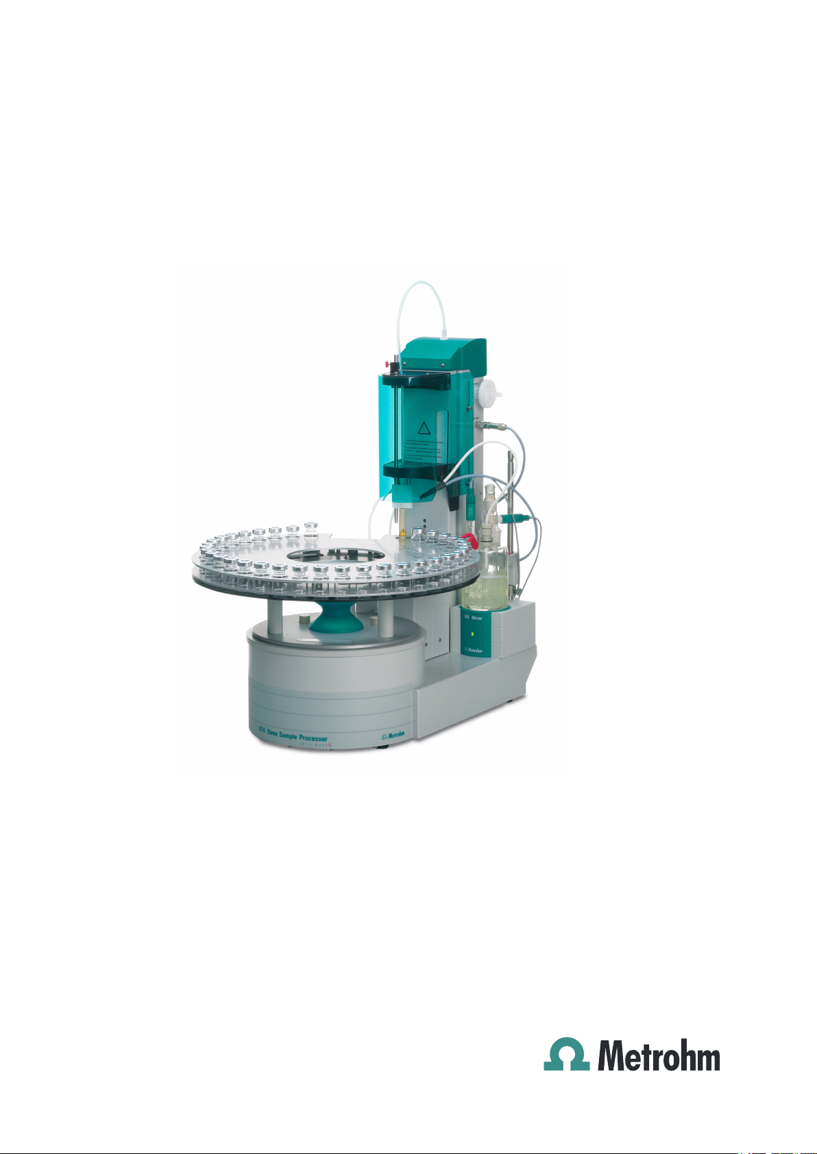
874 Oven Sample Processor
Manual
8.874.8002EN
Page 2

Page 3

Metrohm AG
CH-9101 Herisau
Switzerland
Phone +41 71 353 85 85
Fax +41 71 353 89 01
info@metrohm.com
www.metrohm.com
874 Oven Sample Processor
Manual
8.874.8002EN 06/2011 dm
Page 4

Teachware
Metrohm AG
CH-9101 Herisau
teachware@metrohm.com
This documentation is protected by copyright. All rights reserved.
Although all the information given in this documentation has been
checked with great care, errors cannot be entirely excluded. Should you
notice any mistakes please send us your comments using the address
given above.
Page 5

■■■■■■■■■■■■■■■■■■■■■■
Table of contents
1 Introduction 1
1.1 Instrument description ......................................................... 1
1.1.1 Instrument versions ................................................................. 1
1.1.2 Instrument components .......................................................... 2
1.1.3 Intended use ........................................................................... 2
1.2 About the documentation ................................................... 3
1.2.1 Notation and Pictograms ......................................................... 3
1.3 Safety instructions ................................................................ 4
1.3.1 General notes on safety ........................................................... 4
1.3.2 Electrical safety ........................................................................ 4
1.3.3 Tubing and capillary connections ............................................. 5
1.3.4 Personnel safety ...................................................................... 5
1.3.5 Flammable solvents and chemicals ........................................... 7
1.3.6 Recycling and disposal ............................................................. 7
Table of contents
2 Overview of the instrument 8
3 Installation 12
3.1 Setting up the instrument .................................................. 12
3.1.1 Packaging .............................................................................. 12
3.1.2 Checks .................................................................................. 12
3.1.3 Location ................................................................................ 12
3.2 Connecting a mains cable .................................................. 12
3.3 Mounting the sample insert .............................................. 13
3.4 Mounting the needles ........................................................ 14
3.5 Mounting the heating tube ............................................... 17
3.6 Mounting the drying flasks ............................................... 18
3.7 Mounting the dust filter .................................................... 20
3.8 Mounting the air/nitrogen connector ............................... 20
3.9 Mounting the safety shield ................................................ 22
3.10 Mounting the KF titration cell ........................................... 23
3.11 Inserting the heating tube into the KF titration cell ....... 24
874 Oven Sample Processor
3.12 Attaching the sample rack ................................................. 27
3.13 Adjusting the guide rod ..................................................... 28
3.14 Connecting a computer ..................................................... 28
3.15 Connecting MSB devices ................................................... 30
3.15.1 Connecting dosing devices .................................................... 31
■■■■■■■■
III
Page 6

Table of contents
■■■■■■■■■■■■■■■■■■■■■■
3.15.2 Connecting a stirrer or titration stand .................................... 32
3.15.3 Connecting a remote box ...................................................... 33
3.16 Connecting USB devices ..................................................... 34
3.16.1 Connecting a barcode reader ................................................. 34
4 Processing a sample series 36
5 Handling and maintenance 37
5.1 General ................................................................................ 37
5.2 Care ...................................................................................... 37
5.3 Quality Management and validation with Metrohm ....... 37
6 Troubleshooting 39
6.1 Problems and their solutions ............................................. 39
7 Appendix 40
7.1 Remote interface ................................................................ 40
7.1.1 Pin assignment of the remote interface .................................. 40
7.2 Stirring rate ......................................................................... 42
8 Technical specifications 43
8.1 Lift and turntable ............................................................... 43
8.2 Oven ..................................................................................... 43
8.3 Gas flow .............................................................................. 43
8.4 Outlet heater ....................................................................... 44
8.5 Interfaces and connectors ................................................. 44
8.6 Mains connection ............................................................... 44
8.7 Safety specifications ........................................................... 44
8.8 Electromagnetic compatibility (EMC) ................................ 45
8.9 Ambient temperature ......................................................... 45
8.10 Reference conditions .......................................................... 46
8.11 Dimensions .......................................................................... 46
9 Conformity and warranty 47
9.1 Declaration of Conformity ................................................. 47
■■■■■■■■
IV
9.2 Quality Management Principles ........................................ 48
9.3 Warranty (guarantee) ......................................................... 49
10 Accessories 51
10.1 Scope of delivery 2.874.0010 ............................................ 51
874 Oven Sample Processor
Page 7

■■■■■■■■■■■■■■■■■■■■■■
Index 70
Table of contents
10.2 Scope of delivery 2.874.0020 ............................................ 59
10.3 Optional accessories ........................................................... 66
874 Oven Sample Processor
■■■■■■■■
V
Page 8

Table of figures
Table of figures
Figure 1 Front 874 Oven Sample Processor ..................................................... 8
Figure 2 Rear 874 Oven Sample Processor .................................................... 10
Figure 3 6.2041.720 sample rack .................................................................. 11
Figure 4 Connecting the mains cable ............................................................ 12
Figure 5 Mounting the sample insert ............................................................. 13
Figure 6 Mounting the needles ..................................................................... 15
Figure 7 Mounting the tubing ....................................................................... 16
Figure 8 Mounting the heating tube ............................................................. 17
Figure 9 Preparing the drying flasks ............................................................... 18
Figure 10 Mounting the tubings ..................................................................... 19
Figure 11 Mounting the dust filter .................................................................. 20
Figure 12 External gas connector .................................................................... 21
Figure 13 Mounting the safety shield .............................................................. 22
Figure 14 Coulometric KF titration cell ............................................................ 25
Figure 15 Volumetric KF titration cell .............................................................. 26
Figure 16 Attaching the rack ........................................................................... 27
Figure 17 Adjusting the guide rod ................................................................... 28
Figure 18 Connecting the computer ............................................................... 29
Figure 19 Connecting a dosing device ............................................................. 32
Figure 20 Connecting MSB stirrer .................................................................... 32
Figure 21 Rod Stirrer and titration stand .......................................................... 33
Figure 22 Connecting a remote box ................................................................ 33
Figure 23 USB connectors ............................................................................... 34
Figure 24 Connectors of the remote box ......................................................... 40
Figure 25 Pin assignment of the remote socket and plug ................................ 40
Figure 26 Rotational speed depending on stirring rate .................................... 42
■■■■■■■■■■■■■■■■■■■■■■
■■■■■■■■
VI
874 Oven Sample Processor
Page 9

■■■■■■■■■■■■■■■■■■■■■■
1 Introduction
1.1 Instrument description
The 874 Oven Sample Processor is used whenever the heating up of a
sample and/or the thermal expulsion of moisture in solid substances or liquids is required. In combination with a coulometric or volumetric KF titrator, the 874 Oven Sample Processor is the ideal analysis system for water
determination in samples that contain disruptive components or from
which moisture can be removed only with difficulty.
One of its decisive advantages is the reduction of sample preparation to a
minimum. Thanks to the use of hermetically sealed sample vessels ("headspace vials"), the filling of the samples can be accomplished directly onsite. The PTFE-coated septa guarantee a constant, non-falsified water content, even after prolonged holding times.
1 Introduction
The sample heated in the oven module releases its moisture in the form of
water vapor, which is conveyed into a measuring cell with the aid of a gas
flow. An air pump is installed for the purpose of generating the gas flow.
An inlet valve is available for nitrogen or other inert gases. The determination of the moisture can be accomplished in the measuring cell either coulometrically or volumetrically according to Karl Fischer.
The operation and control of the 874 Oven Sample Processor is accomplished by means of the tiamo™ PC software. This enables convenient
programming of method runs, ranging from the simple to the complex.
The integration of the 874 Oven Sample Processor together with other
instruments (e. g. with a coulometer) using one user interface, makes not
only simple operation possible, but also the evaluation and storage of the
measurement data from all of the linked instruments in one single database.
1.1.1 Instrument versions
The 874 Oven Sample Processor is available in two versions with different
accessories.
■ Version 2.874.0010 with accessories for the usage of standard vials
(volume 6 mL)
■ Version 2.874.0020 without accessories for the usage of standard
vials. Appropriate accessories can be ordered for specific vessel sizes.
874 Oven Sample Processor
■■■■■■■■
1
Page 10

1.1 Instrument description
1.1.2 Instrument components
The 874 Oven Sample Processor has the following components:
■ Oven
Oven module made of aluminum with software-operated temperature
control for heating the sample vessel.
■ Fan
Propeller fan for cooling the oven module.
■ Inlet valve
Valve for switching over the source of the gas flow.
■ Air pump
Pump for generating the gas flow.
■ Outlet heater
Heating tube for preventing the condensation of moisture.
■ Lift with rods
Guidance device with needle adapter and tubing for the gas flow.
■ Turntable
For the standard sample rack with a capacity of 36 sample vials (6 mL)
or the special sample rack with a capacity of 25 sample vials (⌀ = 16 ...
32 mm).
■■■■■■■■■■■■■■■■■■■■■■
1.1.3 Intended use
The 874 Oven Sample Processor is designed for usage as an auxiliary
device for sample preparation in analytical laboratories. Its main area of
application is the moisture determination according to Karl Fischer (coulometric or volumetric). The 874 Oven Sample Processor enables the application of thermal gas extraction technique.
The present instrument is suitable for processing chemicals and flammable
samples. The usage of the 874 Oven Sample Processor therefore requires
that the user has basic knowledge and experience in the handling of toxic
and caustic substances. Knowledge with respect to the application of the
fire prevention measures prescribed for laboratories is also mandatory.
■■■■■■■■
2
874 Oven Sample Processor
Page 11
■■■■■■■■■■■■■■■■■■■■■■
1.2 About the documentation
Caution
Please read through this documentation carefully before putting the
instrument into operation. The documentation contains information
and warnings which have to be followed by the user in order to ensure
safe operation of the instrument.
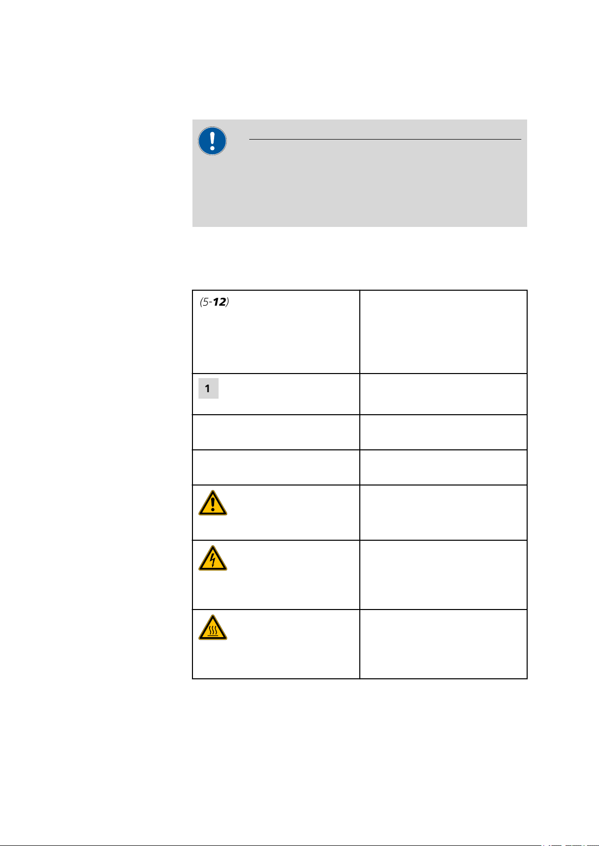
1.2.1 Notation and Pictograms
The following notations and pictograms (symbols) are used in these
Instructions for Use:
1 Introduction
Cross-reference to illustration
legend number
The first number stands for the
number of the illustration, the
second for the legend number.
Instruction step
Follow these steps.
Methode Dialog, Parameter in the soft-
ware
[Weiter] Button in the software or Key on
the keyboard.
Warning
This symbol draws attention to a
possilbe danger of life or injury.
Warning
This symbol draws attention to a
possilbe danger through electrical
current.
Warning
This symbol draws attention to a
possible danger through heat or
hot instrument parts.
874 Oven Sample Processor
■■■■■■■■
3
Page 12
1.3 Safety instructions
1.3 Safety instructions
1.3.1 General notes on safety
Warning
■■■■■■■■■■■■■■■■■■■■■■
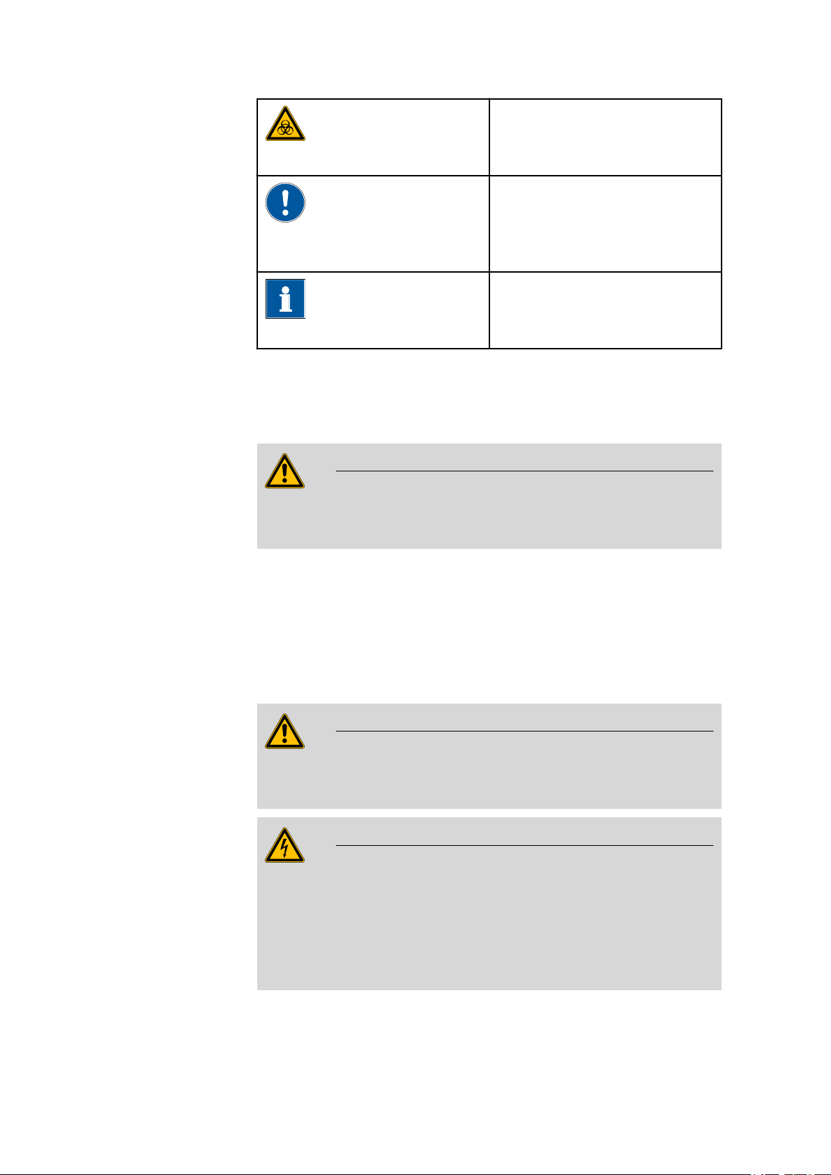
Warning
This symbol draws attention to a
possible biological hazard.
Caution
This symbol draws attention to
possible damage of instruments or
instrument parts.
Comment
This symbol marks additional
information and tips.
This instrument may only be operated in accordance with the specifications in this documentation.
This instrument has left the factory in a flawless state in terms of technical
safety. To maintain this state and ensure non-hazardous operation of the
instrument, the following instructions must be observed carefully.
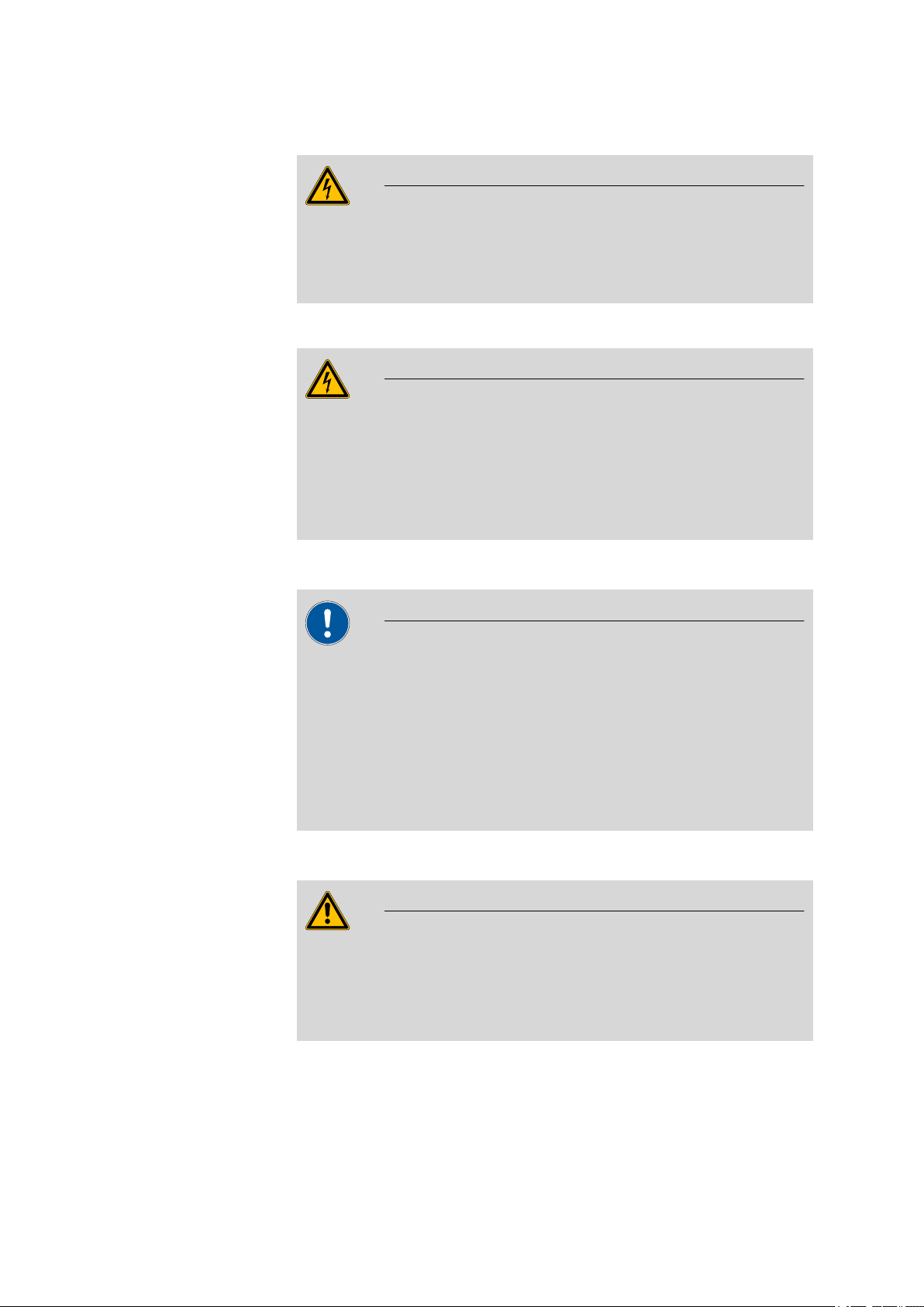
1.3.2 Electrical safety
The electrical safety when working with the instrument is ensured as part
of the international standard IEC 61010.
Only personnel qualified by Metrohm are authorized to carry out service
work on electronic components.
Never open the housing of the instrument. The instrument could be
damaged by this. There is also a risk of serious injury if live components
are touched.
Warning
Warning
■■■■■■■■
4
There are no parts inside the housing which can be serviced or replaced
by the user.
874 Oven Sample Processor
Page 13
■■■■■■■■■■■■■■■■■■■■■■
1 Introduction
Mains voltage
Warning
An incorrect mains voltage can damage the instrument.
Only operate this instrument with a mains voltage specified for it (see
rear panel of the instrument).
Protection against electrostatic charges
Warning
Electronic components are sensitive to electrostatic charges and can be
destroyed by discharges.
Always pull the mains cable out of the mains connection socket before
connecting or disconnecting electrical appliances on the rear panel of
the instrument.
1.3.3 Tubing and capillary connections
Caution
Leaks in tubing and capillary connections are a safety risk. Tighten all
connections well by hand. Avoid applying excessive force to tubing
connections. Damaged tubing ends lead to leakage. Appropriate tools
can be used to loosen connections.
Check the connections regularly for leakage. If the instrument is used
mainly in unattended operation, then weekly inspections are mandatory.
1.3.4 Personnel safety
Warning
Wear protective goggles and working clothes suitable for laboratory
work while operating the 874 Oven Sample Processor. It is also advisable to wear gloves when caustic liquids are used or in situations where
glass vessels could break.
874 Oven Sample Processor
■■■■■■■■
5
Page 14
1.3 Safety instructions
■■■■■■■■■■■■■■■■■■■■■■
Warning
Always install the safety shield supplied with the equipment before
using the instrument for the first time. Pre-installed safety shields are
not allowed to be removed.
The 874 Oven Sample Processor may not be operated without a safety
shield!
Warning
Personnel are not permitted to reach into the working area of the
instrument while operations are running!
A considerable risk of injury exists for the user.
Warning
In the event of a possible blockage of a drive, the mains plug must be
pulled out of the socket immediately. Do not attempt to free jammed
sample vessels or other parts while the device is switched on. Blockages
can only be cleared when the instrument is in a voltage-free status; this
action generally involves a considerable risk of injury.
Warning
The 874 Oven Sample Processor is not suitable for utilization in biochemical, biological or medical environments in its basic equipment version.
Appropriate protective measures must be implemented in the event
that potentially infectious samples or reagents are being processed.
■■■■■■■■
6
874 Oven Sample Processor
Page 15
■■■■■■■■■■■■■■■■■■■■■■
1.3.5 Flammable solvents and chemicals
Warning
All relevant safety measures are to be observed when working with
flammable solvents and chemicals.
■ Set up the instrument in a well-ventilated location.
■ Keep all sources of flame far from the workplace.
■ Clean up spilled fluids and solids immediately.
■ Follow the safety instructions of the chemical manufacturer.
1.3.6 Recycling and disposal
This product is covered by European Directive 2002/96/EC, WEEE – Waste
from Electrical and Electronic Equipment.
The correct disposal of your old equipment will help to prevent negative
effects on the environment and public health.
1 Introduction
More details about the disposal of your old equipment can be obtained
from your local authorities, from waste disposal companies or from your
local dealer.
874 Oven Sample Processor
■■■■■■■■
7
Page 16
2 Overview of the instrument
1
2
3
4
5
6
7
8
9
10
11
12
13
14
15
16
17
18
■■■■■■■■■■■■■■■■■■■■■■
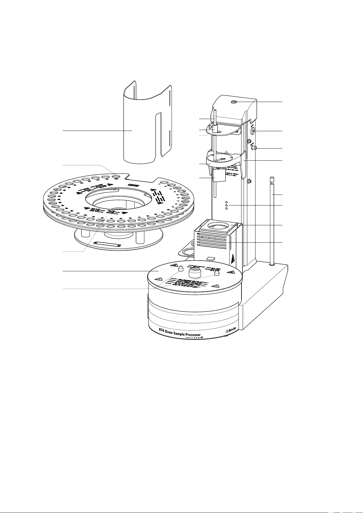
Figure 1 Front 874 Oven Sample Processor
■■■■■■■■
8
874 Oven Sample Processor
Page 17

■■■■■■■■■■■■■■■■■■■■■■
2 Overview of the instrument
Safety shield (6.2751.140)
1
Sample rack (6.2041.720)
3
For 36 sample vials (6 mL).
Guide bolts
5
For the sample rack.
Rod holder
7
With knurled screw.
Working head
9
Gas outlet
11
With M6 thread.
Heating tube connector
13
Support rod (6.2016.030)
15
For fixing the titration cell.
Oven module
17
With PTFE covering.
Conditioning position
2
For the conditioning vessel.
Turntable
4
Guide rod
6
For stripping off the sample vessel.
Guide head
8
Distributor
10
Air pump inlet
12
For the 6.2724.010
Lift
14
Beaker sensor
16
Oven housing
18
With ventilation slits.
874 Oven Sample Processor
■■■■■■■■
9
Page 18
■■■■■■■■■■■■■■■■■■■■■■
USB 2
1
2
3
4
5
6
7
8
9
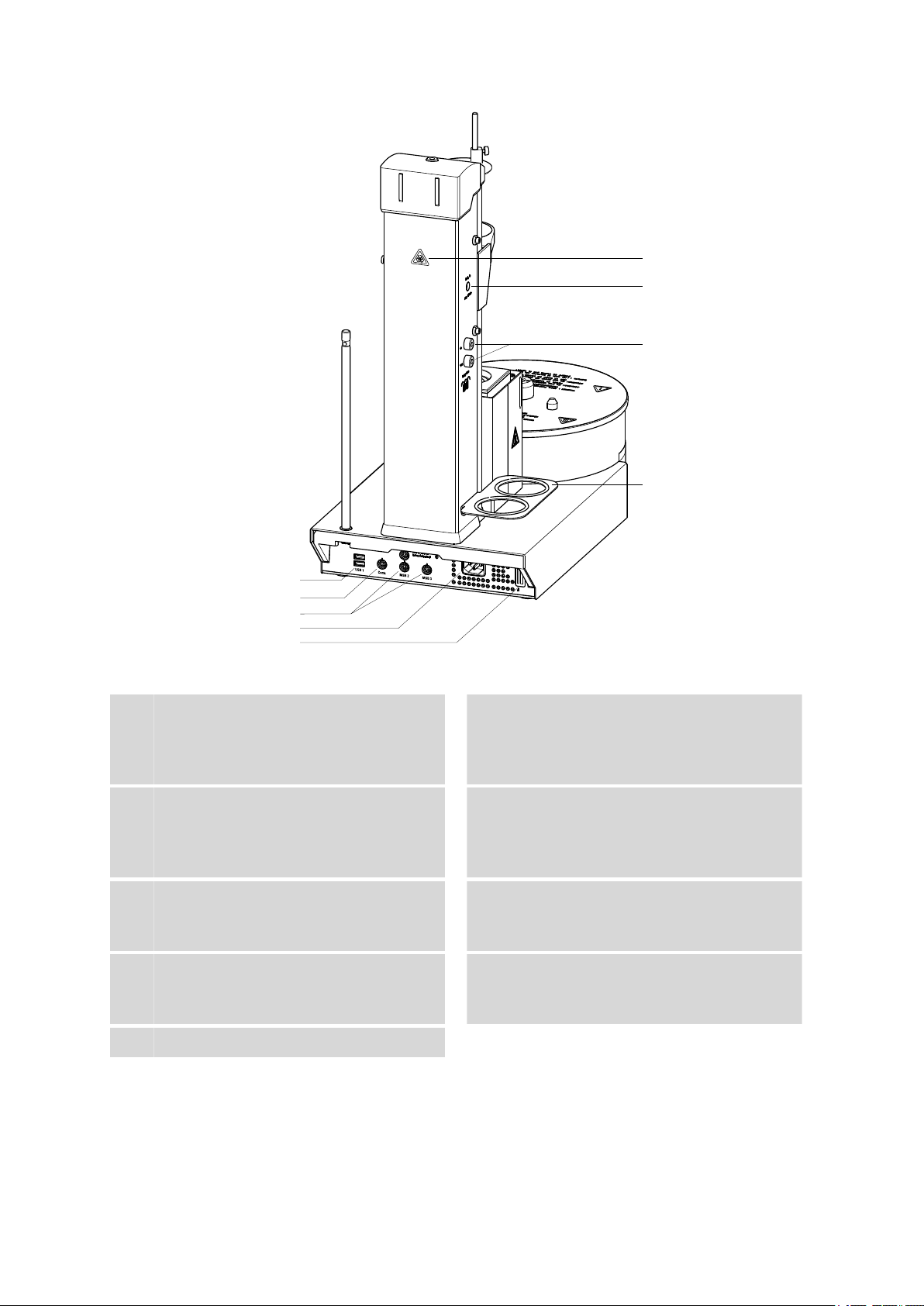
Figure 2 Rear 874 Oven Sample Processor
USB connector (USB 1 and USB 2)
1
USB ports (type A) for connecting a printer,
USB hub, Titrandos, additional USB devices
etc.
MSB connector (MSB 1 to MSB 3)
3
Metrohm Serial Bus. For connecting external
dosing devices, stirrers or remote boxes.
Mini DIN, 9-pin.
Type plate
5
Contains specifications concerning mains
voltage, instrument type and serial number.
Air/nitrogen connector
7
With M6 interior thread. Inlet for external
gassing.
Drying flask holder
9
Controller connector (Controller)
2
For connecting a computer with installed PC
software.
Mains connection socket
4
Warning symbol
6
Biological hazard.(see Chapter 1.3.4, page
5)
Gas inlet and outlet
8
For connecting drying flasks, with M6 inner
thread.
■■■■■■■■
10
874 Oven Sample Processor
Page 19
■■■■■■■■■■■■■■■■■■■■■■
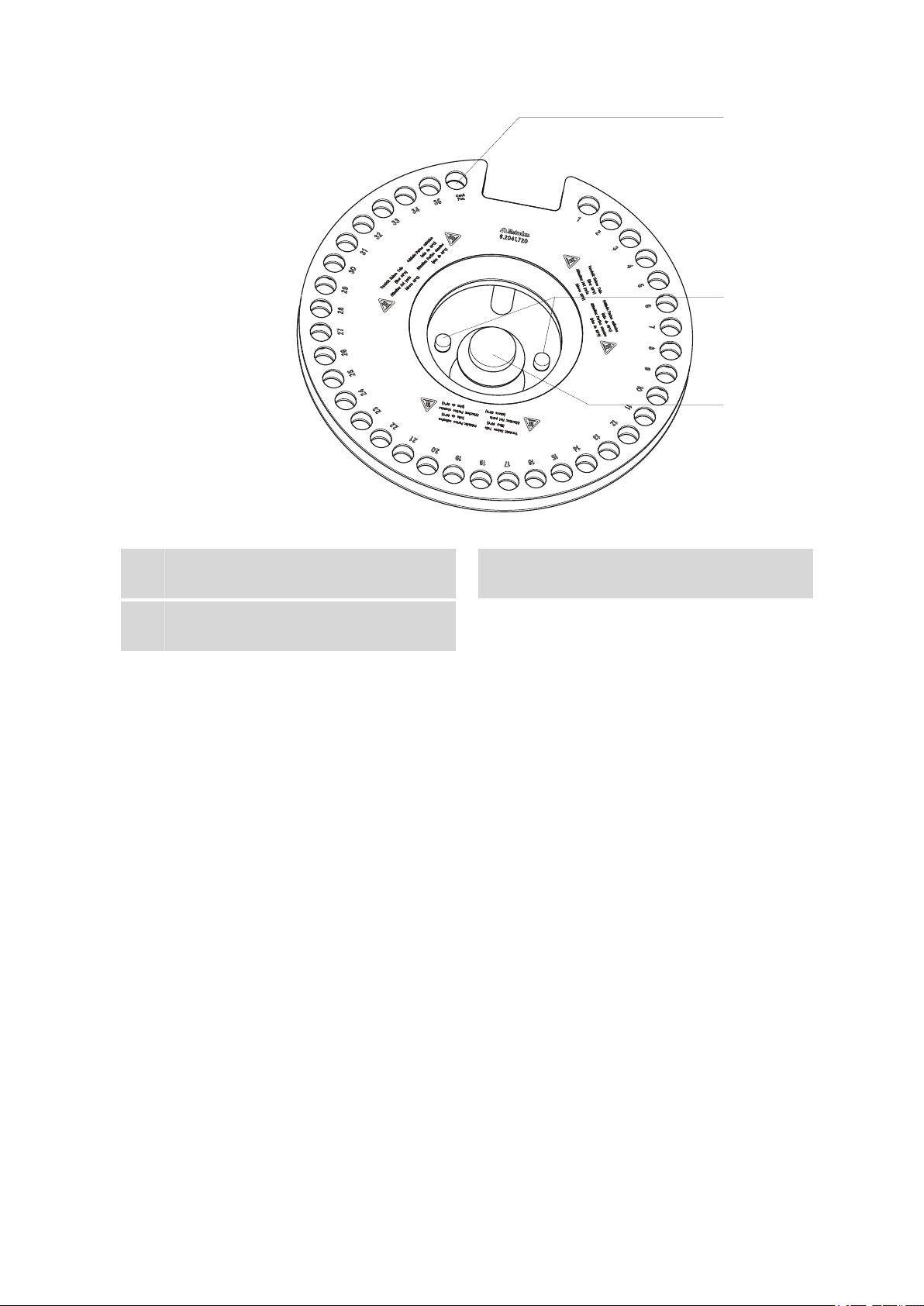
1
2
3
2 Overview of the instrument
Conditioning position
1
For the conditioning vessel.
Handle
3
With fixing screw.
Figure 3 6.2041.720 sample rack
Guide pins
2
874 Oven Sample Processor
■■■■■■■■
11
Page 20

3.1 Setting up the instrument
P: 115W U: 100 - 240 V f: 50 - 60 Hz
Nr.
3 Installation
3.1 Setting up the instrument
3.1.1 Packaging
The instrument is supplied in highly protective special packaging together
with the separately packed accessories. Keep this packaging, as only this
ensures safe transportation of the instrument.
3.1.2 Checks
Immediately after receipt, check whether the shipment has arrived complete and without damage by comparing it with the delivery note.
3.1.3 Location
The instrument has been developed for operation indoors and may not be
used in explosive environments.
■■■■■■■■■■■■■■■■■■■■■■
Place the instrument in a location of the laboratory which is suitable for
operation, free of vibrations, protected from corrosive atmosphere, and
contamination by chemicals.
The instrument should be protected against excessive temperature fluctuations and direct sunlight.
3.2 Connecting a mains cable
Warning
This instrument must not be operated except with the mains voltage
specified for it (see rear panel of the instrument).
Protect the connection sockets against moisture.
■■■■■■■■
12
Figure 4 Connecting the mains cable
874 Oven Sample Processor
Page 21
■■■■■■■■■■■■■■■■■■■■■■
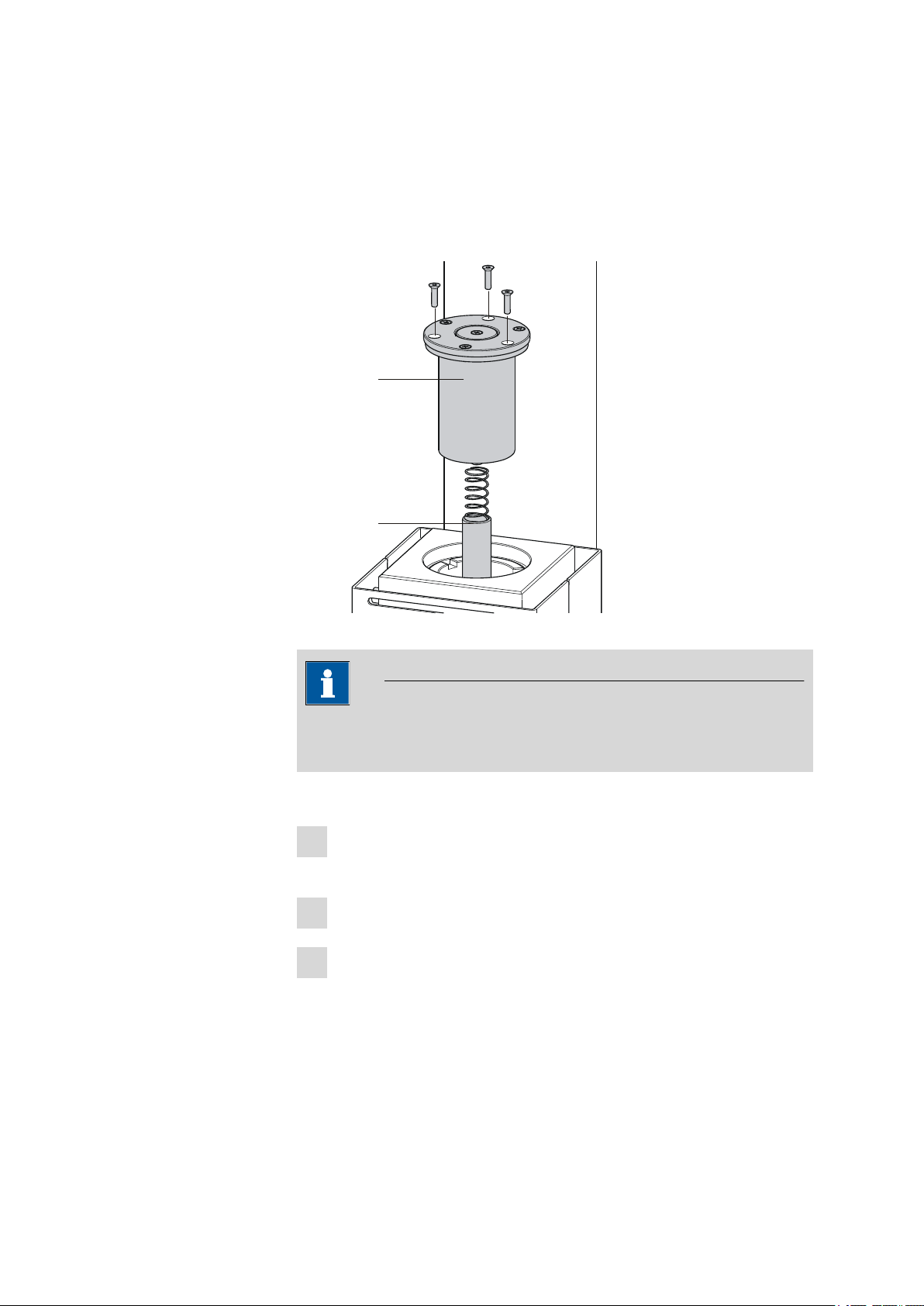
1
2
3
6.2063.020
6.2627.010
3.3 Mounting the sample insert
The dimensions of the supplied sample insert are optimized for the usage
of 6.2419.007 sample vials (6 mL) from Metrohm . This ensures the
best possible transfer of heat between oven and sample.
3 Installation
Figure 5 Mounting the sample insert
Note
The sample insert may not be inserted or removed unless it has been
cooled down.
Proceed as follows:
Insert the 6.2627.010 oven insert with the spring in place into the
1
oven from above and slide it all the way to the bottom.
Place the 6.2063.020 sample insert into the oven from above.
2
Tighten the sample insert with the supplied hexagon screws. The
3
required hexagon key is part of the accessories.
874 Oven Sample Processor
■■■■■■■■
13
Page 22

3.4 Mounting the needles
Note
If vessels with other dimensions are to be used, then individually modified sample inserts can be ordered. The precise vessel dimensions
(including tolerances) will be required when ordering. Non-standard
sample vessels may not exhibit dimensions outside of the following limit
values:
■ Diameter 10.0…32.0 mm
■ Immersion depth 20.0…45.0 mm
3.4 Mounting the needles
Two different types of needle holders are available for mounting needles.
The length of the needle holder defines how deeply the injection needle
penetrates the sample vessel. The 6.2049.040 needle holder, which is
58 mm in length, ensures that the needle penetrates the liquid or powdery sample. The carrier gas can flow through the sample and effect an
efficient expulsion of the moisture it contains.
■■■■■■■■■■■■■■■■■■■■■■
If there is a danger that the heated sample could clog the needle, then
use the 6.2049.050 needle holder with 73 mm length. In this case the
injection needle penetrates the sample vessel only slightly deeper than the
outlet needle and has no contact with the sample itself.
Needle holders with the dimensions required for situations calling for special sample vessels can be supplied by Metrohm upon request.
■■■■■■■■
14
874 Oven Sample Processor
Page 23
■■■■■■■■■■■■■■■■■■■■■■
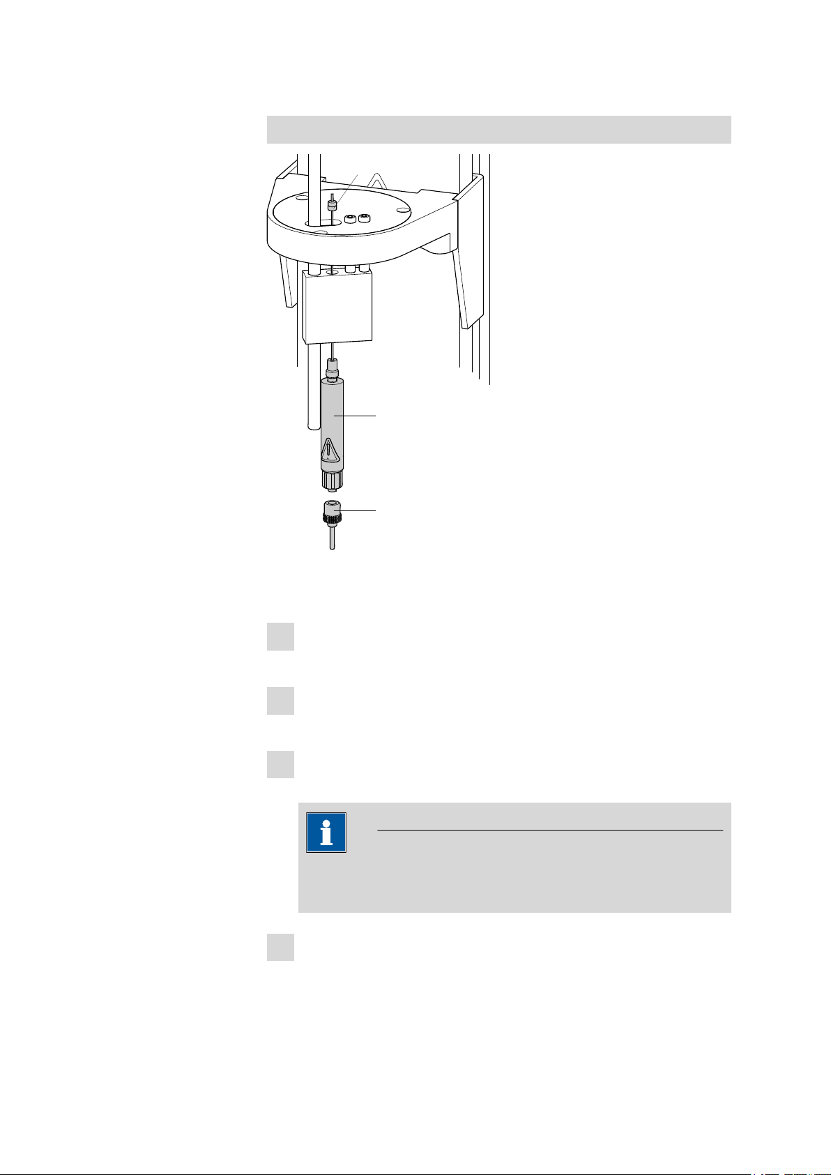
6.2816.080
6.2049.040/6.2049.050
6.2816.070
1
2
3
3 Installation
Mounting the injection and outlet needle
Figure 6 Mounting the needles
Mount the needles as follows
Screw the needle holder (6.2049.040 or 6.2049.050) into the distri-
1
butor on the guide head.
Screw the 6.2816.080 outlet needle onto the Luer connector of
2
the needle holder.
Carefully guide the 6.2816.070 injection needle into the opening
3
of the distributor from above and allow it to drop down.
Note
Take care to ensure that the white PTFE seal is positioned securely
on the needle.
Screw the 6.1805.470 FEP tubing by hand onto the opening of
4
the distributor. Screw the other end of the tube into the opening of
the gas outlet on the upper side of the tower.
874 Oven Sample Processor
■■■■■■■■
15
Page 24
3.4 Mounting the needles
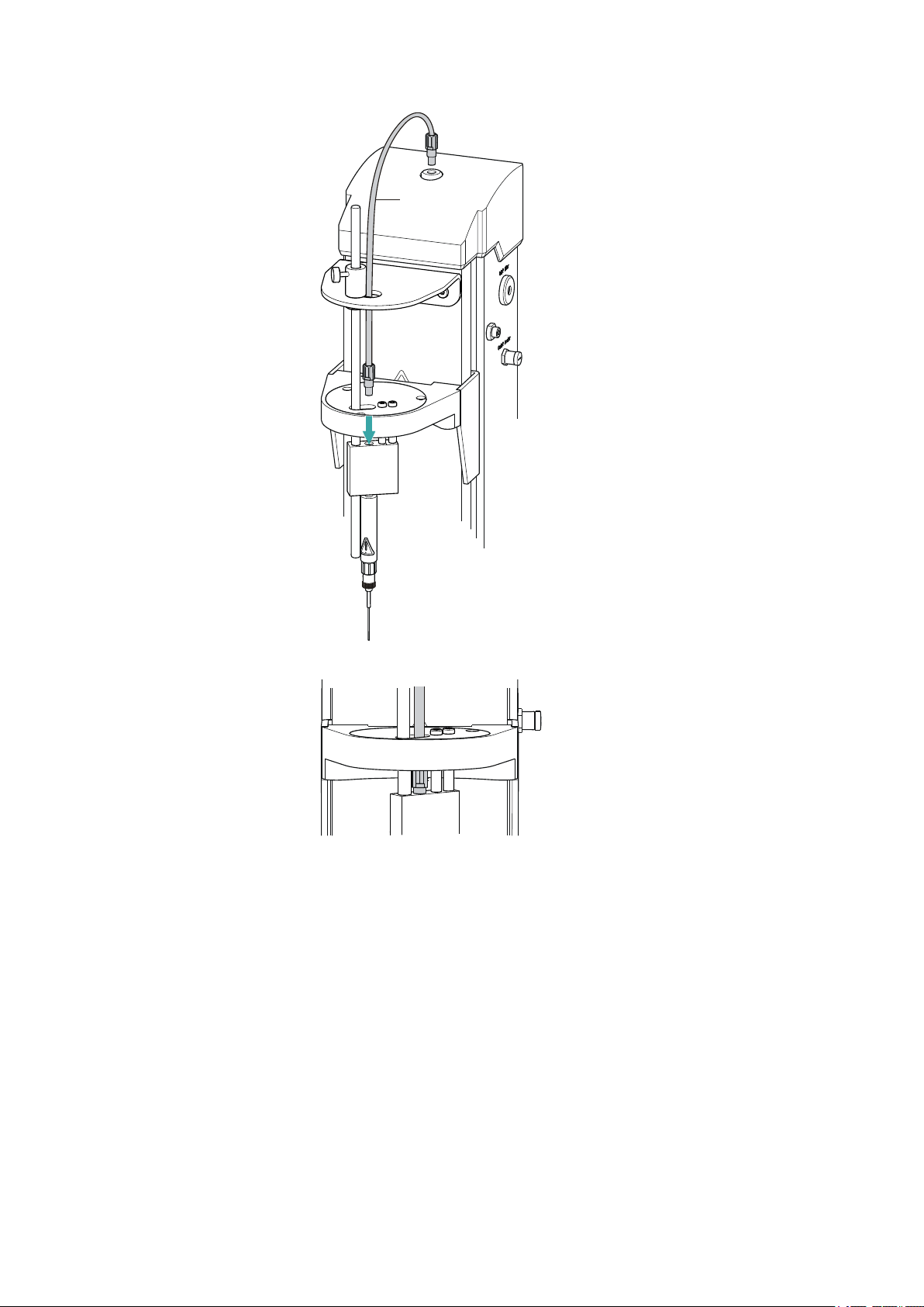
6.1805.470
4
■■■■■■■■■■■■■■■■■■■■■■
Figure 7 Mounting the tubing
■■■■■■■■
16
874 Oven Sample Processor
Page 25

■■■■■■■■■■■■■■■■■■■■■■
1
2
3.5 Mounting the heating tube
Figure 8 Mounting the heating tube
Proceed as follows:
Screw the M6 connector of the 6.1830.030 heating tube into the
1
side opening of the distributor on the guide head.
Connect the heating tube cable to the Outlet heater connector on
2
the right-hand side of the tower.
3 Installation
Rotate the plug in such a way that the three contact pins match the
alignment of the corresponding openings on the socket. Press the
plug against the socket and rotate the front knurled screw in clockwise direction.
Note
The heating jacket of the heating tube is heated up to approx. 40...50
°C as soon as the instrument is switched on. This prevents the condensation of moisture in the tubing when this is expelled from the sample
and transferred with the aid of a carrier gas into a KF titration cell.
874 Oven Sample Processor
■■■■■■■■
17
Page 26

3.6 Mounting the drying flasks
1
2
3
6.1608.050
6.1821.040
6.1602.145
6.2811.000
3.6 Mounting the drying flasks
Two drying flasks with desiccant are integrated into the gas flow in order
to dry the gas that is conveyed. Dust (e.g. from the desiccant) must be
prevented from finding its way into the sample vessel.
Figure 9 Preparing the drying flasks
■■■■■■■■■■■■■■■■■■■■■■
Prepare both drying flasks as follows:
Fill both 6.1608.050 drying flasks with 6.2811.000 molecular
1
sieve.
Screw one 6.1821.040 filter tube into each of the 6.1602.145
2
drying flask covers from below. Tighten the filter tubes well by
hand.
Screw the two drying flask covers with the filter tubes onto the dry-
3
ing flasks. Tighten the covers well by hand.
Note
If the drying flask covers or the filter tubes are not sufficiently
tightly screwed on, then this will prevent a precise, regular flow of
gas. An error message displaying a wrong gas flow rate appears as
a rule when there are leaks in the threaded connections.
■■■■■■■■
18
874 Oven Sample Processor
Page 27

■■■■■■■■■■■■■■■■■■■■■■
1
1
2
2
3
3
4
6.1805.0106.1805.010
6.1805.050
Figure 10 Mounting the tubings
Mount the FEP tubings as follows:
Load the two drying flasks that have been prepared into the holders,
1
see previous illustration.
Screw one 6.1805.050 FEP tubing (18 cm length) to the gas out-
2
let (left-hand side of the tower, labeled to). Screw the other tubing
end on the front drying flask to the M6 connector without a dot
mark (see right-hand arrow).
Screw one 6.1805.010 FEP tubing (13 cm length) to the gas inlet
3
(left-hand side of the tower, labeled from). Screw the other tubing
end on the rear drying flask to the M6 connector with a dot mark
(see left-hand arrow).
Screw the second 6.1805.010 FEP tubing (13 cm length) tightly
4
onto the remaining M6 connectors of the drying flasks.
3 Installation
874 Oven Sample Processor
The marking Drying flask on the left-hand side of the tower displays the diagram for the tubing.
Note
Tighten the screw connections well by hand.
■■■■■■■■
19
Page 28

3.7 Mounting the dust filter
6.2724.010
3.7 Mounting the dust filter
The built-in air pump must be protected against dust. A 6.2724.010
dust filter must be placed on the air inlet (inlet filter) on the right-hand
side of the tower for this reason.
Figure 11 Mounting the dust filter
■■■■■■■■■■■■■■■■■■■■■■
Note
The dust filter should be replaced approx. once a year.
3.8 Mounting the air/nitrogen connector
If compressed air, nitrogen or another gas is to be used for transferring of
expelled moisture, then a separate connector is available.
A tube with M6 thread can be connected directly to the connector Air/N
in on the left-hand side of the tower. Enclosed with the instrument is the
6.1808.040 M6/M8 tubing adapter for tubing with an M8 thread.
The 6.1808.050 M8/tubing olive can also be put in place in order to
connect a simple tube.
2
■■■■■■■■
20
874 Oven Sample Processor
Page 29

■■■■■■■■■■■■■■■■■■■■■■
3 Installation
Figure 12 External gas connector
Warning
If gas is supplied from a pressure line or a pressure vessel, then it is
imperative that a pressure reduction valve be placed upstream. The gas
pressure may not exceed a maximum overpressure level of 0.3 bar.
874 Oven Sample Processor
■■■■■■■■
21
Page 30

3.9 Mounting the safety shield
6.2751.140
1
1
2
2
3
3
3.9 Mounting the safety shield
■■■■■■■■■■■■■■■■■■■■■■
Figure 13 Mounting the safety shield
Warning
It is imperative that the safety shield be installed before the first time
the 874 Oven Sample Processor is used. The device is not permitted to
be operated without a safety shield.
Proceed as follows:
Undo the hexagon screws on both sides of the tower with the
1
enclosed hexagon key.
Move the 6.2751.400 safety shield into position, starting from the
2
top. Observe the corresponding illustration.
Fix the safety shield in place with the hexagon screws.
3
■■■■■■■■
22
874 Oven Sample Processor
Page 31

■■■■■■■■■■■■■■■■■■■■■■
801 Stirrer
6.2013.010
6.2047.020
6.0345.100
6.1403.030
6.0341.100
6.1464.320
1
2
3
4
5
6
7
Note
You can adjust the vertical position of the safety shield at any time
by loosening the screws. Take care to ensure that is not possible to
reach into the working area of the needles while the instrument is
in operation.
3.10 Mounting the KF titration cell
The following description is provided as an example for the mounting of a
coulometric KF titration cell. The necessary accessory parts are, with the
exception of the 6.2013.010 clamping ring, not included in the scope of
delivery of the 874 Oven Sample Processor.
3 Installation
874 Oven Sample Processor
Proceed as follows:
Insert the magnetic stirrer 801 Stirrer from above by means of the
1
support rod at the right-hand side of the tower. Connect the cable to
the coulometer.
Screw the 6.2013.010 clamping ring tightly to the support rod,
2
with the indent facing upward.
Fix the 6.2047.020 titration vessel holder to the support rod.
3
Actuate the fixing lever of the holder while doing so.
■■■■■■■■
23
Page 32

3.11 Inserting the heating tube into the KF titration cell
Fasten the 6.1464.320 coulometric KF titration cell to the titra-
4
tion vessel holder. Hook the metal clip of the titration cell to the
holder.
The height of the titration vessel holder can now be adjusted in such
a way that the titration vessel hangs slightly above the magnetic stirrer. Use the clamping ring to fix the position of the holder. If the fixing lever of the holder is now pressed, then the titration cell can be
raised slightly and swiveled. The correct positioning of the titration
cell continues to be maintained by the clamping ring.
Insert the 6.0345.100 generator electrode (or 6.0344.100) into
5
the titration cell and connect a 6.2104.120 electrode cable to it.
Insert the 6.0341.100 indicator electrode into the titration cell
6
and connect a 6.2104.020 electrode cable to it.
Fill a 6.1403.030 KF adsorber tube with 6.2811.000 molecular
7
sieve. Place a small piece of absorbent cotton underneath and above
the molecular sieve to serve as a dust filter. Insert the filled drying
tube into the titration cell.
Place a 6.1903.030 stirring bar into the titration cell.
8
■■■■■■■■■■■■■■■■■■■■■■
3.11 Inserting the heating tube into the KF titration cell
The 874 Oven Sample Processor can be used in combination with a KF
coulometer or a volumetric KF titrator. The mounting of the tip of the
heating tube is accomplished in different ways for the respective KF titration cells.
Coulometric KF titration cell
■ Remove the protective cover from the tip of the heating tube and the
E.3010.032 O-ring.
■ Disassemble the accompanying 6.1446.170 heating tube stopper
into three parts.
■■■■■■■■
24
874 Oven Sample Processor
Page 33

■■■■■■■■■■■■■■■■■■■■■■
6.1830.030
6.1446.170
1
2
3
Figure 14 Coulometric KF titration cell
Proceed as follows:
Guide the upper part of the heating tube stopper over the tip of the
1
6.1830.030 heating tube as shown in the illustration.
Guide the O-ring of the heating tube stopper over the heating tube.
2
Guide the lower part of the heating tube stopper over the heating
3
tube and screw the three parts together (not too tightly).
Insert the stopper with the tip of the heating tube into one of the
4
two SGJ openings of the KF titration cell
Shift the tip vertically in such a way that the outlet opening of the
5
tubing is immersed as deeply as possible. The tip must not however
be permitted to get in the way of the stirring bar in the KF titration
cell. Afterwards give the heating tube stopper its final tightening.
3 Installation
874 Oven Sample Processor
Volumetric KF titration cell
■ Remove the protective cover from the tip of the heating tube and the
E.3010.032 O-ring. The latter you will still need.
■ A 6.2730.020 septum stopper is enclosed with every KF titrator
made by Metrohm. Disassemble this septum stopper into three parts
and remove the septum. It will not be required.
■■■■■■■■
25
Page 34

3.11 Inserting the heating tube into the KF titration cell
6.1830.030
E.3010.032
6.2730.020
1
2
3
Figure 15 Volumetric KF titration cell
Proceed as follows:
Guide the upper part of the septum stopper over the tip of the
1
6.1830.030 heating tube as shown in the illustration.
Guide the E.3010.032 O-ring over the heating tube.
2
■■■■■■■■■■■■■■■■■■■■■■
This O-ring is also part of the 6.1244.040 set of seals that is enclosed
with each KF titrator. It cannot be reordered individually.
Guide the lower part of the septum stopper over the heating tube
3
and screw the three parts together (not too tightly).
Insert the stopper with the tip of the heating tube into the front
4
opening of the KF titration cell
Shift the height of the tip of the heating tube vertically in such a way
5
that the outlet opening of the tubing is immersed as deeply as possible. The tip must not however be permitted to get in the way of the
stirring bar in the KF titration cell. Afterwards give the septum stopper its final tightening.
■■■■■■■■
26
874 Oven Sample Processor
Page 35

■■■■■■■■■■■■■■■■■■■■■■
1
2
3.12 Attaching the sample rack
3 Installation
Figure 16 Attaching the rack
The turntable of the 874 Oven Sample Processor must be in initial position
before the sample rack can be removed or put into place. To accomplish
this, carry out the [Rack Reset] function in the manual operation of the
control software.
Put the rack into place as follows:
Carefully center the rack on the turntable. The guide bolts on the
1
turntable must engage with the openings in the bottom of the rack.
Tip: hold the rack in such a way that the printed Metrohm logo is
legible horizontally.
Carry out the [Rack Reset] function in the manual operation of the
2
control software.
The rack is moved into starting position. The magnet code of the
rack is read by the instrument during this process. The white arrow in
figure 16 indicates the position of the magnet holder. The six-digit
magnet code is used to identify the rack type. The sample positions
and any special positions on the rack are defined along with the rack
type.
874 Oven Sample Processor
■■■■■■■■
27
Page 36

3.13 Adjusting the guide rod
3.13 Adjusting the guide rod
The needle is pulled out of the sample vial by the upward movement of
the lift. The sample vial is not permitted to remain hanging on the needle
during this procedure. The rod that is fixed to the guide head with a
knurled screw is used to push off the vial. The vertical positioning of the
guide rod must be adjusted, depending on the height of the sample vial.
The guide rod is not permitted to obstruct the sample vial when the rack
is rotated.
■■■■■■■■■■■■■■■■■■■■■■
Figure 17 Adjusting the guide rod
Undo the red knurled screw on the guide head and adjust the height of
the guide rod.
3.14 Connecting a computer
The 874 Oven Sample Processor requires a USB connection to a computer
in order to be able to be controlled by a PC software. When a 6.2151.000
controller cable is used, the instrument can be connected directly, either
to a USB socket on a computer, to a connected USB hub or to a different
Metrohm control instrument.
Cable connection and driver installation
A driver installation is required in order to ensure that the 874 Oven Sample Processor is recognized by the PC software. To accomplish this, you
must comply with the procedures specified. The following steps are necessary:
1
Installing the software
■ Insert the PC software installation CD and carry out the installa-
tion program directions.
■ Exit the program if you have started it after the installation.
■■■■■■■■
28
874 Oven Sample Processor
Page 37

■■■■■■■■■■■■■■■■■■■■■■
6.2151.000
USB 2
USB 1
Contr.
MSB 2
3 Installation
2
Establishing cable connections
■ Connect all peripheral devices to the instrument (see Chapter
3.15, page 30).
■ Connect the 874 Oven Sample Processor to the mains supply if
you have not already done this.
■ Connect the instrument to your computer through a USB connec-
tor (Type A) (see Instructions for Use for your computer). The
6.2151.000 cable is used for this purpose.
Figure 18 Connecting the computer
For Windows 2000: The instrument is recognized and the driver is
installed automatically.
For Windows XP: The instrument is recognized and the installation
assistant for the driver is started automatically. Select the option
"Install software automatically" and click on [Continue]. Exit the
assistant with [Finish].
For Windows Vista: The instrument is recognized and the installation assistant for the driver is started automatically. Select the option
"Find and install driver software". Agree to all subsequent requests.
The installation assistant will be exited automatically.
Note
The plug on the instrument end of the 6.2151.000 controller cable is
protected with an anti-pull device to prevent the cable from being
pulled out accidentally. If you wish to pull out the plug, then you must
first retract the outer plug sleeve marked with arrows.
Registering and configuring the instrument in the PC software
The instrument must be registered in the configuration of your PC software. Once that has been done, you can then configure it according to
your requirements. Proceed as follows:
874 Oven Sample Processor
■■■■■■■■
29
Page 38

3.15 Connecting MSB devices
1
Setting up the instrument
■ Start up the PC software.
The instrument is recognized automatically. The configuration dialog for the instrument is displayed.
■ Make configuration settings for the instrument and its connec-
tors.
More detailed information concerning the configuration of the instument can be found in the documentation for the respective PC software.
3.15 Connecting MSB devices
In order to connect MSB devices, e.g. stirrers or dosing devices, Metrohm
instruments are equipped with up a maximum of four connectors at what
is referred to as the Metrohm Serial Bus (MSB). Various kinds of peripheral
devices can be connected in sequence (in series, as a "daisy chain") at a
single MSB connector (8-pin Mini DIN socket) and controlled simultaneously by the respective control instrument. In addition to the connection
cable, stirrers and the remote box are each equipped with their own MSB
socket for this purpose.
■■■■■■■■■■■■■■■■■■■■■■
The following illustration provides an overview of the devices that can be
connected to an MSB socket, along with a number of different cabling
variations.
The question of which peripheral devices are supported depends on the
control instrument.
Note
When connecting MSB devices together, the following must be
observed:
■ Only one device of the same type can be used at a single MSB con-
nector at one time.
■ Type 700 Dosino and 685 Dosimat dosing devices cannot be con-
nected together with other MSB instruments on a shared connector.
These dosing devices must be connected separately.
■■■■■■■■
30
874 Oven Sample Processor
Page 39

■■■■■■■■■■■■■■■■■■■■■■
Caution
Exit the control software before you plug MSB instruments in. The control instrument recognizes when it is switched on which instrument is
connected at which MSB connector. The operating unit or the control
software enters the connected MSB devices into the system configuration (Device manager).
MSB connections can be extended with the 6.2151.010 cable. The length
of the connection must not exceed a maximum of 15 m.
3.15.1 Connecting dosing devices
Three dosing devices can be connected to the instrument.
The types of dosing devices that are supported are:
■ 800 Dosino
■ 700 Dosino
■ 805 Dosimat
■ 685 Dosimat
3 Installation
Warning
If a Dosino is connected to the 874 Oven Sample Processor, then the
connection cable must be equipped with a ferrite core T.2400.102. The
ferrite core reduces any interference voltages that may occur and thus
ensures compliance with strict EMC standards pursuant to applicable
technical norms, see Chapter "Technical Data".
Proceed as follows:
1
Mounting ferrite core
Fasten a ferrite core T.2400.102 to the Dosino connection cable near
to the plug.
2
Connect a dosing device
■ Exit the control software.
■ Connect the connection cable to one of the sockets marked with
MSB on the rear of the control instrument.
■ Start the control software.
874 Oven Sample Processor
■■■■■■■■
31
Page 40

3.15 Connecting MSB devices
USB 1
Contr.
MSB 2
MSB 3
T.2400.102
USB 1
Contr.
MSB 2
MSB 3
Figure 19 Connecting a dosing device
3.15.2 Connecting a stirrer or titration stand
You can use a magnetic stirrer 801 Stirrer or 803 Ti Stand (stirring "from
below") or the 804 Ti Stand with a rod stirrer 802 Stirrer (stirring "from
above").
Connect a stirrer or a titration stand as follows:
1
Connect a stirrer or titration stand
■ Exit the control software.
■ Connect the connection cable of the magnetic stirrer or of the
titration stand to one of the sockets marked with MSB on the
rear of the control instrument.
■ If desired, connect the rod stirrer to the stirrer socket (with stirrer
symbol) of the titration stand.
■ Start the control software.
■■■■■■■■■■■■■■■■■■■■■■
■■■■■■■■
32
Figure 20 Connecting MSB stirrer
874 Oven Sample Processor
Page 41

■■■■■■■■■■■■■■■■■■■■■■
USB 1
Contr.
MSB 2
MSB 3
Figure 21 Rod Stirrer and titration stand
3.15.3 Connecting a remote box
Instruments that are controlled via remote lines and/or which send control
signals via remote lines can be connected using the 6.2148.010 remote
box. In addition to Metrohm, other instrument manufacturers also use
similar connectors that make it possible to connect different instruments
together. These interfaces are also frequently given the designations "TTL
Logic", "I/O Control" or "Relay Control" and generally have a signal level
of 5 volts.
3 Installation
Control signals are understood to be electrical line statuses or brief
(> 200 ms) electrical pulses which display the operational state of an
instrument or which trigger or report an event. Sequences on a variety of
instruments can thus be coordinated in a single complex automation system. No exchange of data is possible, however.
Proceed as follows:
1
Connect a remote box
■ Exit the control software.
■ Connect the remote box connection cable to one of the sockets
marked with MSB on the rear of the control instrument.
■ Start the control software.
Figure 22 Connecting a remote box
You can, for example, connect an 849 Level Control Box (fill level monitor
in a waste canister) or a 731 Relay Box (switch box for 230/110 volt alternating current sockets and low-voltage direct current outlets). The remote
874 Oven Sample Processor
■■■■■■■■
33
Page 42

3.16 Connecting USB devices
USB 2
USB 1
box also has an MSB socket at which a further MSB instrument, e.g. a
dosing device or a stirrer, can be connected.
You will find precise information concerning the pin assignment of the
interface on the remote box in Appendix (see Chapter 7.1, page 40).
3.16 Connecting USB devices
Two USB connectors (Type A sockets) are available for connecting devices
with USB interfaces. The 874 Oven Sample Processor functions then as a
USB hub (distributor). If you wish to connect more than two USB devices,
you can also use an additional commercially available USB hub.
Note
When a USB device is connected, the control instrument recognizes
which device is connected. The control software automatically enters a
connected USB device into the system configuration (Device manager).
■■■■■■■■■■■■■■■■■■■■■■
3.16.1 Connecting a barcode reader
A barcode reader is used as an input aid for entering text and numbers.
You can connect a barcode reader to a USB interface.
Connect a barcode reader as follows:
1
Connecting the cable
■ Plug the USB plug (Type A) of the barcode reader into one of the
USB sockets on the rear side of the instrument.
Figure 23 USB connectors
2
Configuring the barcode reader in the control software
■ Configure the barcode reader in the configuration part of the
control software as described in the online Software Help.
■■■■■■■■
34
874 Oven Sample Processor
Page 43

■■■■■■■■■■■■■■■■■■■■■■
3 Installation
Settings of the barcode reader
The barcode reader requires certain basic settings. You will find directions
in the Instructions for Use as to how you can program the barcode reader.
Switch the barcode reader to programming mode and make the following
settings:
■ Select the keyboard layout for the desired country (USA, Ger-
1
many, France, Spain, Switzerland (German)). This setting must
match the setting in the control software.
■ Make sure that the Ctrl characters (ASCII 00 to 31) are allowed to
be sent.
■ Adjust the settings so that the ASCII character 02 (STX or Ctrl B) is
sent as the first character as "Preamble" or "Prefix Code".
■ Adjust the settings so that the ASCII character 04 (EOT or Ctrl D) is
sent as the last character as "Postamble" or "Record Suffix" or
"Postfix Code".
■ Exit programming mode.
874 Oven Sample Processor
■■■■■■■■
35
Page 44

4 Processing a sample series
Moisture determinations according to the heating method require the
conditioning of the entire tubing system and of the KF titration cell before
a determination can be carried out. Because the sample vials and the septum seals may contain small amounts of moisture, three to five blank
value determinations must be carried out with sealed, empty vessels. For
conditioning, blank value and sample determinations, example methods
for tiamo™ are to be found in the installation directory of the software.
Preparing
Weigh solid or liquid samples into sample vials and seal these securely
with the septum crimping tongs. We recommend the use of the
6.2419.007 sample vial with the 6.1448.057 septum seals. The silicone
septum of the aluminum cap is resistant to temperatures of up to 250 °C
and has shown iself to be exceptionally reliable. In addition to the sample
vials, you will also require for a sample series an empty, tightly sealed vial
as a conditioning vessel, in addition to three to five vials (which are also
empty and tightly sealed) as blank samples.
■■■■■■■■■■■■■■■■■■■■■■
Place an empty, sealed vial as conditioning vessel at the Cond. Pos.
position on the sample rack of the 874 Oven Sample Processor. The
empty blank samples are placed on Positions 1 to 3 (or 5) on the sample rack. Place the vials filled with samples on the following positions.
In the sample table of tiamo™ one line must be filled out with the associated method and sample data for each vial on the sample rack. Observe
in this connection the explanations contained in the Application note for
the individual methods. The vials must be processed in the correct
sequence. It is for this reason that the sample table must be filled out as
follows:
■ Line 1: conditioning method
■ Lines 2 to 4 (6, resp.): method for blank value determination
■ Lines 5 (7, resp.) to x: method for water content determination
Observe the following during conditioning:
■ In the KF titration cell, the shaft of the heating tube should not be
immersed in the working medium.
■ Align the tip of the heating tube against the vessel wall.
■ Set the stirring rate to high. The carrier gas should emerge from the tip
of the heating tube into the working medium as tiny bubbles and be
spun there forcefully. It is advantageous for air bubbles to be stirred
into the working medium and forcefully broken up in the process. The
air in the KF titration cell must also be dried.
■■■■■■■■
36
874 Oven Sample Processor
Page 45

■■■■■■■■■■■■■■■■■■■■■■
5 Handling and maintenance
5.1 General
The 874 Oven Sample Processor requires appropriate care. Excess contamination of the instrument may result in functional disruptions and a reduction in the service life of the sturdy mechanics and electronics of the
instrument.
Severe contamination can also have an influence on the measured results.
Regular cleaning of exposed parts can prevent this to a large extent.
Spilled chemicals and solvents must be removed immediately. In particular,
the mains plug should be protected from contamination.
5.2 Care
5 Handling and maintenance
■ Replace exhausted molecular sieve promptly. You should replace the
molecular sieve as soon as increased drift values appear in the Karl
Fischer cell.
■ Check all tubing connections regularly for leaks.
■ Flush out the tubing connections from time to time. Carefully dry the
tubing afterward. The tubing must be replaced after prolonged usage.
■ Clean the sample insert regularly with a damp cloth.
■ Replace the dust filter once a year.
5.3 Quality Management and validation with Metrohm
Quality Management
Metrohm offers you comprehensive support in implementing quality management measures for instruments and software. Further information on
this can be found in the brochure «Quality Management with
Metrohm» available from your local Metrohm agent.
Validation
Please contact your local Metrohm agent for support in validating instruments and software. Here you can also obtain validation documentation
to provide help for carrying out the Installation Qualification (IQ) and
the Operational Qualification (OQ). IQ and OQ are also offered as a
service by the Metrohm agents. In addition, various application bulletins
are also available on the subject, which also contain Standard Operat-
ing Procedures (SOP) for testing analytical measuring instruments for
reproducibility and correctness.
874 Oven Sample Processor
■■■■■■■■
37
Page 46

5.3 Quality Management and validation with Metrohm
Maintenance
Electronic and mechanical functional groups in Metrohm instruments can
and should be checked as part of regular maintenance by specialist personnel from Metrohm. Please ask your local Metrohm agent regarding the
precise terms and conditions involved in concluding a corresponding
maintenance agreement.
Note
You can find information on the subjects of quality management, validation and maintenance as well as an overview of the documents currently available at www.metrohm.com/com/ under Support.
■■■■■■■■■■■■■■■■■■■■■■
■■■■■■■■
38
874 Oven Sample Processor
Page 47

■■■■■■■■■■■■■■■■■■■■■■
6 Troubleshooting
6.1 Problems and their solutions
Problem Cause Remedy
6 Troubleshooting
The drift is very high
during conditioning.
The titration time is
too long.
The results are
spread widely.
Molecular sieve of drying
flasks and/or the titration
cell exhausted.
The titration cell is leaking.
The sample is non-homogenous
Not the entirety of the
moisture is expelled.
Tubing connections leaking
Molecular sieve of drying
flasks exhausted.
Condensate in the heating
tube.
Gas flow too high.
Replace molecular sieve.
Check seals. If necessary, replace.
Reduce the size of the sample or homogenize
it before weighing in.
Select more stringent switch-off criteria on the
KF titrator: lower stop drift, higher switch-off
delay time.
Inspect tubing and replace as necessary.
Replace molecular sieve.
■ Dry the tubing.
■ Reduce the gas flow.
■ Perhaps lower the oven temperature.
Reduce the gas flow.
Selected gas flow is
not achieved.
874 Oven Sample Processor
The sample is non-homogenous
System is leaking
Pressure from external gas
supply either too low or
too high.
Pump defective
Reduce the size of the sample or homogenize
it before weighing in.
Check all tubing connections and drying flasks
for leaks.
Adjust gas pressure (max. 0.3 bar).
Contact a service technician.
■■■■■■■■
39
Page 48

7.1 Remote interface
1
2
3
13
1
14
25
1
13
14
25
7 Appendix
7.1 Remote interface
The 6.2148.010 remote box allows devices to be controlled which cannot
be connected directly to the MSB interface of the Sample Processor.
■■■■■■■■■■■■■■■■■■■■■■
Figure 24 Connectors of the remote box
Cable
1
For connecting the Sample Processor.
Remote connector
3
For connecting devices with a remote interface.
MSB connector
2
Metrohm Serial Bus. For connecting external
dosing devices or stirrers.
7.1.1 Pin assignment of the remote interface
Figure 25 Pin assignment of the remote socket and plug
The above presentation of the pin assignment of a Metrohm remote interface applies not only for the remote box, but also for all Metrohm devices
with 25-pin D-Sub remote connection.
■■■■■■■■
40
874 Oven Sample Processor
Page 49

■■■■■■■■■■■■■■■■■■■■■■
+5 V
t
p
t
p
7 Appendix
Inputs
approx. 50 kΩ Pull-up
tp >20 ms
active = low, inactive = high
The input lines can be scanned with the SCAN command.
Outputs
Open Collector
tp >200 ms
active = low, inactive = high
IC = 20 mA, V
CEO
= 40 V
+5 V: maximum load = 20 mA
The output lines can be set with the CONTROL command.
Table 1 Inputs and outputs of the remote interface
Assigment Pin No. Assigment Pin No.
Input 0 21 Output 0 5
Input 1 9 Output 1 18
Input 2 22 Output 2 4
Input 3 10 Output 3 17
Input 4 23 Output 4 3
Input 5 11 Output 5 16
Input 6 24 Output 6 1
Input 7 12 Output 7 2
0 volts / GND 14 Output 8 6
+5 volts 15 Output 9 7
0 volts / GND 25 Output 10 8
Output 11 13
Output 12 19
Output 13 20
874 Oven Sample Processor
■■■■■■■■
41
Page 50

7.2 Stirring rate
2000
1500
1000
500
-15 -10 -5 0 5 10 15
r/min
7.2 Stirring rate
The stirring rate can be adjusted in steps of –15 to +15.
The approximate rotational speed can be calculated with the following
formula:
Example:
Stirring rate set: 8
Rotational speed in rpm = 125 · 8 = 1000
■■■■■■■■■■■■■■■■■■■■■■
Rotational speed/min (r/min) = 125 · stirring rate
Figure 26 Rotational speed depending on stirring rate
■■■■■■■■
42
874 Oven Sample Processor
Page 51

■■■■■■■■■■■■■■■■■■■■■■
8 Technical specifications
8.1 Lift and turntable
8 Technical specifications
Stroke path
Maximum lift load
Lift rate
Shift rate
8.2 Oven
Temperature
range
Accuracy
Correction range
Heating cartridge
performance
Heating rate
Cooling rate
154 mm
Approx. 30 N
Adjustable, 5…25 mm/s
Adjustable, 3...20 angular degrees/sec
50…250 °C
±3 °C
-10…+10 °C
Typically 165 W (with 230 V)
Depending on mains voltage
Typically 15 °C/min (with 80…180 °C, 230 V)
Dependent on temperature, mains voltage, sample amount and vessel
dimensions
Typically 9 °C/min (with 80…180 °C)
Dependent on temperature, sample amount and vessel dimensions
8.3 Gas flow
Flow range
874 Oven Sample Processor
10…150 mL/min
Under normal conditions
■■■■■■■■
43
Page 52

8.4 Outlet heater
8.4 Outlet heater
■■■■■■■■■■■■■■■■■■■■■■
Socket connection
Typical tubing
temperature
U = 16 ±1 V
I≤ 0.8 A
Approx. 50 °C
8.5 Interfaces and connectors
Controller connection
MSB connectors
MSB1…MSB3
USB connectors
1/2
USB upstream port (9-pin Mini DIN socket) for connecting a computer
to the control system of the device.
Three 9-pin Mini DIN sockets for connecting dosing devices, stirrers,
etc.
Two USB downstream ports (type A sockets), each 500 mA, for connecting Metrohm instruments or USB peripheral devices of other manufacturers.
8.6 Mains connection
Voltage
100…120 / 220…240 V
Note: It is not allowed to run the instrument between the stated
ranges.
Frequency
Power consumption
Fuse
50 / 60 Hz (± 3%)
200 W
2.0 ATH
8.7 Safety specifications
Design and testing
Safety instructions
According to EN/IEC 61010-1, UL 61010-1, CSA-C22.2 No. 61010-1,
EN/IEC 61010-2-010, EN/IEC 61010-2-081, protection class Ⅰ
This document contains safety instructions which have to be followed
by the user in order to ensure safe operation of the instrument.
■■■■■■■■
44
874 Oven Sample Processor
Page 53

■■■■■■■■■■■■■■■■■■■■■■
8.8 Electromagnetic compatibility (EMC)
8 Technical specifications
Emission
Immunity
Standards fulfilled
■ EN/IEC 61326-1
■ EN/IEC 61000-6-3
■ EN 55022 / CISPR 22
■ EN/IEC 61000-3-2
■ EN/IEC 61000-3-3
Standards fulfilled
■ EN/IEC 61326-1
■ EN/IEC 61000-6-2
■ EN/IEC 61000-4-2
■ EN/IEC 61000-4-3
■ EN/IEC 61000-4-4
■ EN/IEC 61000-4-5
■ EN/IEC 61000-4-6
■ EN/IEC 61000-4-8
■ EN/IEC 61000-4-11
■ EN/IEC 61000-4-14
■ EN/IEC 61000-4-28
■ NAMUR
8.9 Ambient temperature
Nominal function
range
Storage
Transport
5…45 °C
Humidity < 80 %
–20…70 °C
Humidity < 95 %
–40…70 °C
Humidity < 95 %
874 Oven Sample Processor
■■■■■■■■
45
Page 54

8.10 Reference conditions
8.10 Reference conditions
■■■■■■■■■■■■■■■■■■■■■■
Ambient temperature
Relative humidity
Mains voltage
25 °C (±3 °C)
≤60 %
230 V
8.11 Dimensions
Width
Height
Depth
Weight (without
accessories)
Material
Housing
0.28 m
0.55 m
0.49 m
15.50 kg
Metal housing, surface-treated
Oven covering: PTFE
■■■■■■■■
46
874 Oven Sample Processor
Page 55

■■■■■■■■■■■■■■■■■■■■■■
9 Conformity and warranty
9.1 Declaration of Conformity
This is to certify the conformity to the standard specifications for electrical
appliances and accessories, as well as to the standard specifications for
security and to system validation issued by the manufacturing company.
9 Conformity and warranty
Name of commodity
Electromagnetic
compatibility
874 Oven Sample Processor
Sample Processor with temperature-controlled oven unit for the automatic sample treatment in coulometric or volumetric water determinations.
This instrument has been built and has undergone final type testing
according to the standards:
Emission: EN/IEC 61326-1: 2006, EN/IEC 61000-6-3: 2004,
EN 55022 / CISPR 22: 2006,
EN/IEC 61000-3-2: 2006,
EN/IEC 61000-3-3: 2005
Immunity: EN/IEC 61326-1: 2006, EN/IEC 61000-6-2: 2005,
EN/IEC 61000-4-2: 2001,
EN/IEC 61000-4-3: 2002,
EN/IEC 61000-4-4: 2004,
EN/IEC 61000-4-5: 2001,
EN/IEC 61000-4-6: 2001,
EN/IEC 61000-4-8: 2001,
EN/IEC 61000-4-11: 2004,
EN/IEC 61000-4-14: 2004,
EN/IEC 61000-4-28: 2004, NAMUR: 2004
Safety specifications
874 Oven Sample Processor
EN/IEC 61010-1: 2001, UL 61010-1: 2004,
CSA-C22.2 No. 61010-1: 2004, EN/IEC 61010-2-081: 2003, protection
class I
This instrument meets the requirements of the CE mark as contained in
the EU directives 2006/95/EC (LVD), 2004/108/EC (EMC). It fulfils the following specifications:
EN 61326-1 Electrical equipment for measurement, control
and laboratory use – EMC requirements
■■■■■■■■
47
Page 56

9.2 Quality Management Principles
■■■■■■■■■■■■■■■■■■■■■■
EN 61010-1 Safety requirements for electrical equipment for
measurement, control and laboratory use
EN 61010-2-010 Particular requirements for laboratory equipment
for the heating of materials
EN 61010-2-081 Particular requirements for automatic and semi-
automatic laboratory equipment for analysis and
other purposes
Manufacturer
Metrohm Ltd., CH-9101 Herisau/Switzerland
Metrohm Ltd. is holder of the SQS-certificate ISO 9001:2000 Quality management system for development, production and sales of instruments
and accessories for ion analysis.
Herisau, 27 November, 2007
D. Strohm
Vice President, Head of R&D
9.2 Quality Management Principles
Metrohm Ltd. holds the ISO 9001:2000 Certificate, registration number
10872-02, issued by SQS (Swiss Association for Quality and Management
Systems). Internal and external audits are carried out periodically to assure
that the standards defined by Metrohm’s QM Manual are maintained.
A. Dellenbach
Head of Quality Management
■■■■■■■■
48
The steps involved in the design, manufacture and servicing of instruments
are fully documented and the resulting reports are archived for ten years.
The development of software for PCs and instruments is also duly documented and the documents and source codes are archived. Both remain
the possession of Metrohm. A non-disclosure agreement may be asked to
be provided by those requiring access to them.
The implementation of the ISO 9001:2000 quality management system is
described in Metrohm’s QM Manual, which comprises detailed instructions on the following fields of activity:
Instrument development
The organization of the instrument design, its planning and the intermediate controls are fully documented and traceable. Laboratory testing
accompanies all phases of instrument development.
874 Oven Sample Processor
Page 57

■■■■■■■■■■■■■■■■■■■■■■
9 Conformity and warranty
Software development
Software development occurs in terms of the software life cycle. Tests are
performed to detect programming errors and to assess the program’s
functionality in a laboratory environment.
Components
All components used in the Metrohm instruments have to satisfy the quality standards that are defined and implemented for our products. Suppliers of components are audited by Metrohm as the need arises.
Manufacture
The measures put into practice in the production of our instruments guarantee a constant quality standard. Production planning and manufacturing
procedures, maintenance of production means and testing of components, intermediate and finished products are prescribed.
Customer support and service
Customer support involves all phases of instrument acquisition and use by
the customer, i.e. consulting to define the adequate equipment for the
analytical problem at hand, delivery of the equipment, user manuals, training, after-sales service and processing of customer complaints. The
Metrohm service organization is equipped to support customers in implementing standards such as GLP, GMP, ISO 900X, in performing Operational Qualification and Performance Verification of the system components or in carrying out the System Validation for the quantitative determination of a substance in a given matrix.
9.3 Warranty (guarantee)
Metrohm guarantees that the deliveries and services it provides are free
from material, design or manufacturing errors. The warranty period is 36
months from the day of delivery; for day and night operation it is 18
months. The warranty remains valid on condition that the service is provided by an authorized Metrohm service organization.
Glass breakage is excluded from the warranty for electrodes and other
glassware. The warranty for the accuracy corresponds to the technical
specifications given in this manual. For components from third parties that
make up a considerable part of our instrument, the manufacturer's warranty provisions apply. Warranty claims cannot be pursued if the Customer
has not complied with the obligations to make payment on time.
During the warranty period Metrohm undertakes, at its own choice, to
either repair at its own premises, free of charge, any instruments that can
be shown to be faulty or to replace them. Transport costs are to the Customer's account.
874 Oven Sample Processor
■■■■■■■■
49
Page 58

9.3 Warranty (guarantee)
■■■■■■■■■■■■■■■■■■■■■■
Faults arising from circumstances that are not the responsibility of
Metrohm, such as improper storage or improper use, etc. are expressly
excluded from the warranty.
■■■■■■■■
50
874 Oven Sample Processor
Page 59

■■■■■■■■■■■■■■■■■■■■■■
10 Accessories
Note
Subject to change without notice.
10.1 Scope of delivery 2.874.0010
Qty. Order no. Description
1 1.874.0010 874 Oven Sample Processor
Sample Changer for driving out the moisture contained in liquid or
solid samples, followed by coulometric or volumetric moisture determinations according to Karl Fischer. For standard vials (6 mL).
10 Accessories
1 6.1446.170 Heating tube stopper
for coulometric KF vessels in connection with heatable tubing connection
Material: PP
Height (mm): 34
Outer diameter (mm): 13
3 6.1448.057 Aluminum septum caps / 100 pieces
Including Al sealing.
Material: Aluminum
Material 2: Silicone
Height (mm): 7.4
Outer diameter (mm): 20.7
2 6.1602.145 Drying flask cover
Screw cap with GL45 thread for 6.1608.050 drying bottle.
874 Oven Sample Processor
■■■■■■■■
51
Page 60

10.1 Scope of delivery 2.874.0010
Qty. Order no. Description
2 6.1608.050 Drying bottle / 100 mL / GL 45
Material: Clear glass
Height (mm): 100
Outer diameter (mm): 56
Volume (mL): 100
2 6.1805.010 FEP tubing / M6 / 13 cm
With light and kink protection.
Material: FEP
Inner diameter (mm): 2
Length (mm): 130
■■■■■■■■■■■■■■■■■■■■■■
1 6.1805.050 FEP tubing / M6 / 18 cm
With light and kink protection
Material: FEP
Inner diameter (mm): 2
Length (mm): 180
■■■■■■■■
52
874 Oven Sample Processor
Page 61

■■■■■■■■■■■■■■■■■■■■■■
Qty. Order no. Description
1 6.1805.470 FEP tubing / M6 / 44 cm
With light and kink protection
Material: FEP
Inner diameter (mm): 2
Length (mm): 440
1 6.1808.040 Thread adapter M6 outer / M8 inner
Outer thread M6, inner thread M8.
Material: PTCFE
10 Accessories
1 6.1808.050 Tubing adapter olive / M8 outer
1 M8 outer thread and 1 tubing olive. E.g. for thermostat jacket of
exchange units and stability measuring instruments.
Material: PVDF
Length (mm): 31.5
874 Oven Sample Processor
■■■■■■■■
53
Page 62

10.1 Scope of delivery 2.874.0010
Qty. Order no. Description
2 6.1821.040 Filter tube
Filter tube for 6.1608.050 drying bottle. For Rancimats and Karl
Fischer ovens.
Length (mm): 112
1 6.1830.030 Heatable outlet tubing
Heatable outlet tubing for 860 KF Thermoprep and 874 USB Oven
Sample Processor.
■■■■■■■■■■■■■■■■■■■■■■
1 6.2013.010 Clamping ring
For stand rods of 10 mm diameter
Material: Metal
Width (mm): 20
Height (mm): 16
1 6.2041.720 Sample rack 36 x 6 mL for 874
Sample rack for 36 x 6 mL sample vials (6.2419.000), one-row
Hole diameter (mm): 22
■■■■■■■■
54
874 Oven Sample Processor
Page 63

■■■■■■■■■■■■■■■■■■■■■■
Qty. Order no. Description
1 6.2049.040 Needle holder with Luer-lock
Length (mm): 58
1 6.2049.050 Needle holder with Luer-lock
Length (mm): 73
10 Accessories
1 6.2053.000 Cable clip
Cable clip for fastening cables and tubes
1 6.2063.020 Sample holder
Sample holder for 6 mL sample vials (6.2419.000), for 874
874 Oven Sample Processor
■■■■■■■■
55
Page 64

10.1 Scope of delivery 2.874.0010
Qty. Order no. Description
1 6.2151.000 Cable USB A – Mini-DIN 8 pins
Controller cable
Length (m): 1.8
3 6.2419.007 Sample vial 6 ml / 100 pieces
6.1448.050 septum caps. Used for KF-determinations with oven.
Volume (mL): 6
1 6.2621.100 Hexagon key 3 mm
Hexagon key 3 mm for IC Sample Processors
Length (mm): 73
■■■■■■■■■■■■■■■■■■■■■■
1 6.2621.110 Crimping tongs
Crimping tongs for sealing 6 mL sample vials (6.2419.000,
6.2419.007).
Length (mm): 210
■■■■■■■■
56
874 Oven Sample Processor
Page 65

■■■■■■■■■■■■■■■■■■■■■■
Qty. Order no. Description
1 6.2621.130 Hexagon key 2 mm
2 mm.
1 6.2621.140 Hexagon key 2.5 mm
10 Accessories
1 6.2627.010 Oven insert
Used with 874 USB Oven Sample Processor
1 6.2724.010 Dust filter
Dust filter for Rancimats and Karl Fischer ovens.
Outer diameter (mm): 44
Length (mm): 53
874 Oven Sample Processor
■■■■■■■■
57
Page 66

10.1 Scope of delivery 2.874.0010
Qty. Order no. Description
1 6.2739.000 Wrench
For tightening connectors
Length (mm): 68
1 6.2751.140 Splash protection
Splash protection for 874 USB Oven Sample Processor, made of
PMMA
■■■■■■■■■■■■■■■■■■■■■■
1 6.2811.000 Molecular sieve
Molecular sieve. Bottle containing 250 g. Pore size: 0.3 nm. Without
moisture indicator. For Rancimats and Karl Fischer instruments.
1 6.2816.070 Injection needle
Used with Karl Fischer ovens.
Material: Stainless steel (AISI 304)
■■■■■■■■
58
874 Oven Sample Processor
Page 67

■■■■■■■■■■■■■■■■■■■■■■
Qty. Order no. Description
1 6.2816.080 Outlet needle
Used with KF Thermoprep and Oven Sample Processor.
Material: Stainless steel (AISI 304)
1 6.6056.202 tiamo 2.0 Full
Program for controlling complex titration systems. - Graphical
method editor with numerous templates - Layout Manager for display adjustment - Professional database with recalculation - Export to
LIMS, NuGenesis, Cyberlab etc. - Powerful report generator - Complies with FDA 21 CFR Part 11.
10 Accessories
1 6.2122.0x0 Mains cable with C13 line socket
IEC-60320-C13
Cable plug according to customer requirements.
Switzerland: Type SEV 12
6.2122.020
Germany, …: Type CEE(7), VII
6.2122.040
USA, …: Type NEMA/ASA
6.2122.070
1 8.874.8002EN 874 Oven Sample Processor Manual
10.2 Scope of delivery 2.874.0020
Qty. Order no. Description
1 1.874.0010 874 Oven Sample Processor
Sample Changer for driving out the moisture contained in liquid or
solid samples, followed by coulometric or volumetric moisture determinations according to Karl Fischer. For user-defined sample vials (6
mL).
874 Oven Sample Processor
■■■■■■■■
59
Page 68

10.2 Scope of delivery 2.874.0020
Qty. Order no. Description
1 6.1446.170 Heating tube stopper
for coulometric KF vessels in connection with heatable tubing connection
Material: PP
Height (mm): 34
Outer diameter (mm): 13
2 6.1602.145 Drying flask cover
Screw cap with GL45 thread for 6.1608.050 drying bottle.
■■■■■■■■■■■■■■■■■■■■■■
2 6.1608.050 Drying bottle / 100 mL / GL 45
Material: Clear glass
Height (mm): 100
Outer diameter (mm): 56
Volume (mL): 100
2 6.1805.010 FEP tubing / M6 / 13 cm
With light and kink protection.
Material: FEP
Inner diameter (mm): 2
Length (mm): 130
■■■■■■■■
60
874 Oven Sample Processor
Page 69

■■■■■■■■■■■■■■■■■■■■■■
Qty. Order no. Description
1 6.1805.050 FEP tubing / M6 / 18 cm
With light and kink protection
Material: FEP
Inner diameter (mm): 2
Length (mm): 180
1 6.1805.470 FEP tubing / M6 / 44 cm
With light and kink protection
Material: FEP
Inner diameter (mm): 2
Length (mm): 440
10 Accessories
1 6.1808.040 Thread adapter M6 outer / M8 inner
Outer thread M6, inner thread M8.
Material: PTCFE
874 Oven Sample Processor
■■■■■■■■
61
Page 70

10.2 Scope of delivery 2.874.0020
Qty. Order no. Description
1 6.1808.050 Tubing adapter olive / M8 outer
1 M8 outer thread and 1 tubing olive. E.g. for thermostat jacket of
exchange units and stability measuring instruments.
Material: PVDF
Length (mm): 31.5
2 6.1821.040 Filter tube
Filter tube for 6.1608.050 drying bottle. For Rancimats and Karl
Fischer ovens.
Length (mm): 112
■■■■■■■■■■■■■■■■■■■■■■
1 6.1830.030 Heatable outlet tubing
Heatable outlet tubing for 860 KF Thermoprep.
1 6.2013.010 Clamping ring
For stand rods of 10 mm diameter
Material: Metal
Width (mm): 20
Height (mm): 16
■■■■■■■■
62
874 Oven Sample Processor
Page 71

■■■■■■■■■■■■■■■■■■■■■■
Qty. Order no. Description
1 6.2053.000 Cable clip
Cable clip for fastening cables and tubes
1 6.2063.020 Sample holder
Sample holder for 6 mL sample vials (6.2419.000), for 874
1 6.2151.000 Cable USB A – Mini-DIN 8 pins
Controller cable
Length (m): 1.8
10 Accessories
1 6.2621.100 Hexagon key 3 mm
Hexagon key 3 mm for IC Sample Processors
Length (mm): 73
1 6.2621.130 Hexagon key 2 mm
2 mm.
874 Oven Sample Processor
■■■■■■■■
63
Page 72

10.2 Scope of delivery 2.874.0020
Qty. Order no. Description
1 6.2621.140 Hexagon key 2.5 mm
1 6.2627.010 Oven insert
Used with 874 USB Oven Sample Processor
■■■■■■■■■■■■■■■■■■■■■■
1 6.2724.010 Dust filter
Dust filter for Rancimats and Karl Fischer ovens.
Outer diameter (mm): 44
Length (mm): 53
1 6.2739.000 Wrench
For tightening connectors
Length (mm): 68
■■■■■■■■
64
874 Oven Sample Processor
Page 73

■■■■■■■■■■■■■■■■■■■■■■
Qty. Order no. Description
1 6.2751.140 Splash protection
Splash protection for 874 USB Oven Sample Processor, made of
PMMA
1 6.2811.000 Molecular sieve
Molecular sieve. Bottle containing 250 g. Pore size: 0.3 nm. Without
moisture indicator. For Rancimats and Karl Fischer instruments.
10 Accessories
1 6.2816.070 Injection needle
Used with 832 KF Thermoprep.
Material: Stainless steel (AISI 304)
874 Oven Sample Processor
■■■■■■■■
65
Page 74

10.3 Optional accessories
Qty. Order no. Description
1 6.2816.080 Outlet needle
Used with KF Thermoprep and Oven Sample Processor.
Material: Stainless steel (AISI 304)
1 6.6056.202 tiamo 2.0 Full
Program for controlling complex titration systems. - Graphical
method editor with numerous templates - Layout Manager for display adjustment - Professional database with recalculation - Export to
LIMS, NuGenesis, Cyberlab etc. - Powerful report generator - Complies with FDA 21 CFR Part 11.
■■■■■■■■■■■■■■■■■■■■■■
1 6.2122.0x0 Mains cable with C13 line socket
IEC-60320-C13
Cable plug according to customer requirements.
Switzerland: Type SEV 12
6.2122.020
Germany, …: Type CEE(7), VII
6.2122.040
USA, …: Type NEMA/ASA
6.2122.070
1 8.874.8002EN 874 Oven Sample Processor Manual
10.3 Optional accessories
Order no. Description
2.756.0110 756 KF Coulometer including diaphragmless generator electrode
KF Coulometer with titration cell without diaphragm and integrated printer for
water determination right down to trace levels. The 756 KF Coulometer has
established itself for the determination of very small amounts of water. Thanks
to its reliability, backlit graphical display, multilingual dialog and easy operation,
the 756 KF Coulometer has become standard equipment in many laboratories.
■■■■■■■■
66
874 Oven Sample Processor
Page 75

■■■■■■■■■■■■■■■■■■■■■■
Order no. Description
The clear display provides information about the relevant titration parameters
and gives an unmistakable presentation of the course of titration in the form of
a curve showing µg water against time. Recommended measuring range: 10
µg...200 mg absolute water
Dimensions in mm (W/H/D): 145/ 194/ 307
2.800.0010 800 Dosino
Drive with write/read hardware for intelligent dosing units. With fixed cable.
2.801.0010 801 Stirrer
Magnetic stirrer without stand for use with Titrino plus, Titrandos, Sample Processors, 805 Dosimats and 780/781 pH Meters. With permanently attached
cable for MSB (Metrohm Serial Bus).
10 Accessories
2.831.0110 831 KF Coulometer incl. diaphragmless generator
electrode
Economical KF Coulometer with diaphragmless titration cell for water determination right down to trace levels. The KF Coulometer has established itself for
the determination of very small amounts of water. Thanks to its reliability, backlit graphical display, multilingual dialog and easy operation, the 756 KF Coulometer has become standard equipment in many laboratories. The clear display
provides information about the relevant titration parameters and gives an
unmistakable presentation of the course of titration in the form of a curve
showing µg water against time. Recommended measuring range: 10 µg...200
mg absolute water
Dimensions in mm (W/H/D): 145/ 169/ 307
2.841.0010 841 Titrando
The Karl Fischer Titrando for the modern titration laboratory. In addition to the
Karl Fischer mode (KFT), this high-end titrator also includes the SET mode, which
means that titrations can be carried out to a predefined endpoint. The high-resolution, galvanically separated measuring interface means that it is also possible
to make high-precision pH measurements. Thanks to its four MSB connections
up to four 800 Dosino dosing systems can be connected to the 841 Titrando.
These can be used for titration as well as for the automated addition of sample,
standard and auxiliary solutions such as solubility promoters. All liquid handling
commands are also available, which means that the aspiration of used reagent
and the addition of fresh solvent can be automated.
874 Oven Sample Processor
■■■■■■■■
67
Page 76

10.3 Optional accessories
Order no. Description
Dimensions in mm (W/H/D): 142/ 227/ 231
6.2041.730 Sample rack 25 x 2-30 mL, for 874 USB Oven Sample
Processor
Sample rack with 25 positions. Can be adapted to sample vials (diameter: 16 to
32.9 mm).
Hole diameter (mm): 33
6.1448.050 Aluminum septum caps / 1000 pieces
Including Al sealing.
Material: Aluminum
Material 2: Silicone
Height (mm): 7.4
Outer diameter (mm): 20.7
6.2419.000 Sample vial 6 mL / 1000 pieces
For 6.1448.050 septum caps.
Height (mm): 38
Outer diameter (mm): 22
Volume (mL): 6
■■■■■■■■■■■■■■■■■■■■■■
6.3032.120 Dosing Unit 2 mL
Dosing unit with integrated data chip with 2 mL glass cylinder and light protection, mountable on reagent bottle with ISO/DIN GL45 glass thread. FEP tubing
connection, antidiffusion buret tip.
Volume (mL): 2
6.3032.150 Dosing Unit 5 mL
Dosing unit with integrated data chip with 5 mL glass cylinder and light protection, mountable on reagent bottle with ISO/DIN GL45 thread. FEP tubing connection, antidiffusion buret tip.
Volume (mL): 5
6.3032.210 Dosing Unit 10 mL
Dosing unit with integrated data chip with 10 mL glass cylinder and light protection, mountable on reagent bottle with ISO/DIN GL45 thread. FEP tubing connection, antidiffusion buret tip.
Volume (mL): 10
■■■■■■■■
68
874 Oven Sample Processor
Page 77

■■■■■■■■■■■■■■■■■■■■■■
Order no. Description
6.3032.220 Dosing Unit 20 mL
Dosing unit with integrated data chip with 20 mL glass cylinder and light protection, mountable on reagent bottle with ISO/DIN GL45 thread. FEP tubing connection, antidiffusion buret tip.
Volume (mL): 20
6.3032.250 Dosing unit 50 mL
Dosing unit with integrated data chip with 50 mL glass cylinder and light protection, mountable on reagent bottle with ISO/DIN GL45 thread. FEP tubing connection, antidiffusion buret tip.
Volume (mL): 50
6.5618.000 Measuring equipment for checking the temperature
Measuring equipment for checking the temperature of 774/874 Oven Sample
Processor, 832/860 Thermoprep.
10 Accessories
874 Oven Sample Processor
■■■■■■■■
69
Page 78

Index
Index
■■■■■■■■■■■■■■■■■■■■■■
Numbers/Symbols
685 Dosimat ............................ 31
700 Dosino .............................. 31
800 Dosino .............................. 31
801 Stirrer ................................ 32
803 Ti Stand ............................. 32
804 Ti Stand ............................. 32
805 Dosimat ............................ 31
A
Adsorber tube .......................... 24
Air inlet .................................... 20
C
Clamping ring ........................... 23
Computer
connecting ......................... 28
Connecting
Computer ........................... 28
Dosing devices ................... 31
MSB devices ....................... 30
Remote box ........................ 33
Stirrer or titration stand ...... 32
Connector
Air/nitrogen ........................ 10
Controller ........................... 10
MSB ................................... 10
USB .................................... 10
Controller cable 6.2151.000 ..... 28
Coulometric KF titration cell ...... 23
D
Dosing devices
Connecting ........................ 31
Driver
Installing ............................. 28
Drying flask .............................. 19
Drying flasks ............................. 18
Dust filter ............................. 9, 20
E
Electrode .................................. 24
Electrostatic charge .................... 5
Error message
Gas flow rate ...................... 18
External gas connector ............. 21
F
Ferrite core
Mounting ........................... 31
Filter tube ................................. 18
G
Generator electrode ................. 24
GLP .......................................... 37
Guarantee ................................ 49
Guide rod ................................. 28
H
Heating tube ...................... 17, 24
I
Indicator electrode ................... 24
Inert gas ................................... 20
Inlet
Air pump .............................. 9
Inlet filter .................................. 20
Installation
Driver ................................. 28
Instrument type ........................ 10
K
KF titration cell ................... 23, 24
Coulometric ....................... 24
Volumetric .......................... 25
M
Magnetic stirrer ........................ 23
Magnetic Stirrer
Connecting ........................ 32
Mains connection ..................... 10
Mains voltage ............................. 5
Maintenance ............................ 37
Metrohm Serial Bus MSB, see also
"MSB" ...................................... 30
Molecular sieve .................. 18, 24
Mounting
Drying flasks ....................... 18
Dust filter ........................... 20
Heating tube ...................... 17
KF titration cell ............. 23, 24
Magnetic stirrer .................. 23
Needle holder ..................... 14
Needles .............................. 14
Nitrogen connector ............ 20
Oven insert ......................... 13
Safety shield ....................... 22
Sample insert ...................... 13
Tubings .............................. 19
MSB
Connecting devices ............ 30
N
Needle holder ........................... 15
Needles .................................... 14
Nitrogen connector .................. 20
O
Outlet heater ............................ 17
Outlet needle ........................... 15
Oven insert ............................... 13
P
Piercing needle ......................... 15
Pins .......................................... 40
Q
Quality Management ................ 37
R
Remote
Input .................................. 41
Interface ............................. 40
Output ............................... 41
Remote box
Connecting ........................ 33
Pin assignment ................... 40
S
Safety instructions ...................... 4
Safety shield ............................. 22
Sample insert ............................ 13
Sample vessel ........................... 14
Sample vials .............................. 13
Screw connections ................... 19
Serial number ........................... 10
Service ....................................... 4
Service Agreement ................... 37
Stirrer
Connecting ........................ 32
Stirring rate .............................. 42
Support rod .............................. 23
T
Titration cell ............................. 23
Titration stand .......................... 32
Connecting ........................ 32
Transfer tubing ......................... 17
Tubings .................................... 19
■■■■■■■■
70
874 Oven Sample Processor
Page 79

■■■■■■■■■■■■■■■■■■■■■■
Index
V
Validation ................................. 37
Vessel ....................................... 14
W
Warranty .................................. 49
Windows .................................. 29
874 Oven Sample Processor
■■■■■■■■
71
 Loading...