

Page 1
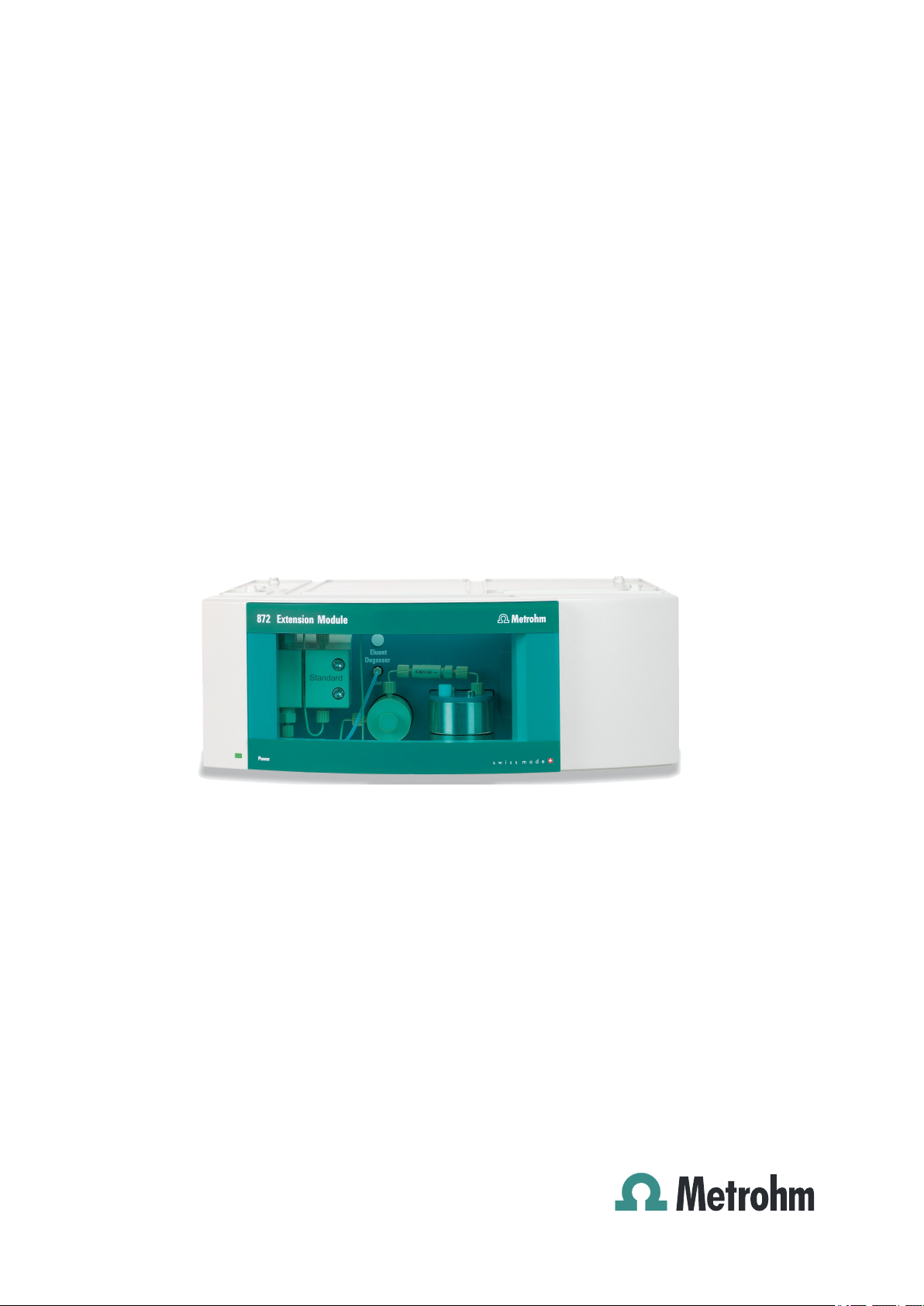
872 Extension Module
IC Module – 2.872.0030
Manual
8.872.8004EN
Page 2

Page 3

Metrohm AG
CH-9100 Herisau
Switzerland
Phone +41 71 353 85 85
Fax +41 71 353 89 01
info@metrohm.com
www.metrohm.com
872 Extension Module
IC Module – 2.872.0030
8.872.8004EN
Manual
01.2010 zst
Page 4

Teachware
Metrohm AG
CH-9100 Herisau
teachware@metrohm.com
This documentation is protected by copyright. All rights reserved.
Although all the information given in this documentation has been
checked with great care, errors cannot be entirely excluded. Should you
notice any mistakes please send us your comments using the address
given above.
Documentation in additional languages can be found on
http://products.metrohm.com under Literature/Technical documenta-
tion.
Page 5

■■■■■■■■■■■■■■■■■■■■■■
Table of contents
1 Introduction 1
1.1 Instrument description ......................................................... 1
1.2 Intended use ......................................................................... 2
1.3 About the documentation ................................................... 2
1.3.1 Content and scope .................................................................. 2
1.3.2 Symbols and conventions ........................................................ 3
1.4 Safety instructions ................................................................ 4
1.4.1 General notes on safety ........................................................... 4
1.4.2 Electrical safety ........................................................................ 4
1.4.3 Tubing and capillary connections ............................................. 5
1.4.4 Flammable solvents and chemicals ........................................... 5
1.4.5 Recycling and disposal ............................................................. 5
2 Overview of the instrument 7
Table of contents
2.1 Front ...................................................................................... 7
2.2 Rear ........................................................................................ 8
3 Assembly 9
3.1 General .................................................................................. 9
3.2 Mounting the extension module onto the IC instru-
ment ..................................................................................... 10
3.3 Mounting the extension module below the IC instru-
ment ..................................................................................... 13
3.4 Setting up the extension module next to the IC instru-
ment ..................................................................................... 16
3.5 Transport locking screws ................................................... 20
4 Installation 21
4.1 About this chapter .............................................................. 21
4.2 Installation overview .......................................................... 21
4.3 Installation diagram ........................................................... 22
4.4 Eluent ................................................................................... 23
4.4.1 Connecting eluent bottle ....................................................... 23
872 Extension Module IC Module
4.5 Eluent degasser ................................................................. 27
4.6 High pressure pump ........................................................... 29
4.6.1 Capillary connections high pressure pump/purge valve ........... 29
4.6.2 Deaerating the high pressure pump ....................................... 31
■■■■■■■■
III
Page 6

Table of contents
■■■■■■■■■■■■■■■■■■■■■■
4.7 Inline filter ........................................................................... 33
4.8 Pulsation damper ............................................................... 34
4.9 Injection valve ..................................................................... 35
4.9.1 Connecting the injection valve ............................................... 35
4.9.2 Mode of operation of the injection valve ............................... 37
4.9.3 Selecting the sample loop ...................................................... 38
5 Set to work 39
6 Operation and maintenance 40
6.1 General information ........................................................... 40
6.1.1 Care ...................................................................................... 40
6.1.2 Maintenance by Metrohm Service .......................................... 40
6.1.3 Operation .............................................................................. 40
6.1.4 Shutting down ...................................................................... 41
6.2 Door ..................................................................................... 41
6.3 Eluent ................................................................................... 41
6.3.1 Production ............................................................................. 41
6.3.2 Operation .............................................................................. 42
6.4 High pressure pump ........................................................... 42
6.4.1 Protection .............................................................................. 42
6.4.2 Maintenance ......................................................................... 43
6.5 Inline filter ........................................................................... 53
6.5.1 Maintenance ......................................................................... 53
6.6 Inline sample preparation .................................................. 55
6.7 Rinsing the sample path .................................................... 55
6.8 Injection valve .................................................................... 57
6.8.1 Protection .............................................................................. 57
6.9 Quality Management and validation with Metrohm ....... 57
7 Troubleshooting 58
7.1 Problems and their solutions ............................................. 58
8 Technical specifications 60
8.1 Reference conditions .......................................................... 60
8.2 Instrument ........................................................................... 60
8.3 Ambient conditions ............................................................ 60
■■■■■■■■
IV
8.4 Housing ............................................................................... 61
8.5 Eluent degasser .................................................................. 61
8.6 High pressure pump ........................................................... 61
8.7 Injection valve ..................................................................... 62
872 Extension Module IC Module
Page 7

■■■■■■■■■■■■■■■■■■■■■■
9 Conformity and warranty 64
10 Accessories 68
Index 75
Table of contents
8.8 Interfaces ............................................................................. 62
8.9 Safety specification ............................................................ 62
8.10 Electromagnetic compatibility (EMC) ................................ 63
8.11 Weight ................................................................................. 63
9.1 Declaration of Conformity ................................................ 64
9.2 Quality Management Principles ........................................ 65
9.3 Warranty (Guarantee) ........................................................ 66
10.1 Scope of delivery ................................................................ 68
872 Extension Module IC Module
■■■■■■■■
V
Page 8

Table of figures
Table of figures
Figure 1 Front 872 Extension Module IC Module ............................................. 7
Figure 2 Rear 872 Extension Module IC Module .............................................. 8
Figure 3 Setup versions ................................................................................. 10
Figure 4 Dismounting the bottle holder ......................................................... 11
Figure 5 Mounting the bottle holder ............................................................. 12
Figure 6 Removing the base tray ................................................................... 14
Figure 7 Mounting the base tray ................................................................... 15
Figure 8 Mounting the base tray ................................................................... 17
Figure 9 Mounting the bottle holder ............................................................. 18
Figure 10 Connecting the drainage tubings ..................................................... 19
Figure 11 Installation diagram ......................................................................... 23
Figure 12 Installing eluent bottle attachment .................................................. 24
Figure 13 Mounting aspiration filter ................................................................ 24
Figure 14 Install tubing weighting and aspiration filter .................................... 25
Figure 15 Eluent aspiration tubing fully equipped. ........................................... 25
Figure 16 Eluent bottle – connected ............................................................... 26
Figure 17 Eluent degasser ............................................................................... 28
Figure 18 Capillary connections high pressure pump/purge valve .................... 29
Figure 19 High pressure pump – Connect inlet ................................................ 30
Figure 20 Deaerating the high pressure pump ................................................. 32
Figure 21 Connecting inline filter .................................................................... 34
Figure 22 Pulsation damper – Connection ....................................................... 35
Figure 23 Injection valve – connected ............................................................. 36
Figure 24 Injection valve – Positions ................................................................ 37
Figure 25 Removing piston ............................................................................. 44
Figure 26 Components of the piston cartridge ................................................ 45
Figure 27 Tool for piston seal 6.2617.010 ....................................................... 46
Figure 28 Removing the piston seal ................................................................. 47
Figure 29 Insert the piston seal into the tool ................................................... 47
Figure 30 Inserting the piston seal into the pump head ................................... 48
Figure 31 Removing valves .............................................................................. 49
Figure 32 Dismantling valve ............................................................................ 50
Figure 33 Components of the inlet valve and outlet valve ................................ 51
Figure 34 Changing the filter .......................................................................... 53
■■■■■■■■■■■■■■■■■■■■■■
■■■■■■■■
VI
872 Extension Module IC Module
Page 9

■■■■■■■■■■■■■■■■■■■■■■
1 Introduction
1.1 Instrument description
Existing 850 Professional IC instruments can be expanded to include additional functions by means of 872 Extension Modules. Every 850 Professional IC instrument can be supplemented with up to 3 extension modules.
The 872 Extension Module IC Module allows to extend an 850 Professional IC instrument by another IC Module complete with high pressure
pump, purge valve, inline filter, pulsation damper and injection valve.
The 872 Extension Module IC Module can be used wherever an additional IC Module is necessary.
With the 872 Extension Module IC Module, a one-channel low pressure
gradient instrument can this way be extended to a two-channel AnCat
instrument with low pressure gradient. All instruments with sample preparation can be extended to two-channel systems as well.
1 Introduction
In a system with photometric detection with a 886 Professional Thermostat/Reactor as column holder and thermostat and an 887 Professional
UV/VIS Detector, it is also possible to use the 872 Extension Module IC
Module for conveying reagents.
The extension module is operated with MagIC Net software, just like the
IC instrument. When it is connected to an 850 Professional IC instrument,
MagIC Net recognizes the extension module automatically and checks its
functional capability. It controls and monitors the unit IC instrument –
extension module, evaluates the measured data and administers it in a
database.
The 872 Extension Module – IC Module comprises the following components:
Eluent degasser
The eluent degasser removes gas bubbles and dissolved gases from the
eluent. For degassing, the eluent flows into a vacuum chamber through a
special fluoropolymer capillary.
High pressure pump
The intelligent and low pulsation high pressure pump pumps the eluent
through the system. It is equipped with a chip on which its technical specifications and "life history" (operating hours, service data, ... ) are saved.
872 Extension Module IC Module
■■■■■■■■
1
Page 10

1.2 Intended use
■■■■■■■■■■■■■■■■■■■■■■
Inline filter
Inline filters protect the separation column securely against possible contamination from the eluent. Inline filters can however also just as well be
used for the purpose of protecting other sensitive components against
contaminations in the solutions used. The fine 2 µm material of the readily
and easily replaceable filter platelets removes particles such as bacteria
and algae from the solutions.
Pulsation damper
The pulsation damper protects the separation column from damage
caused by pressure fluctuations when switching the injection valve, and
reduces interfering pulsations during highly sensitive measurements.
Injection valve
The injection valve connects the eluent and sample path through rapid
and precise valve switchover. A precisely measured amount of sample
solution is injected and rinsed with eluent onto the separation column.
1.2 Intended use
The present instrument is suitable for processing chemicals and flammable
samples. The usage of the 872 Extension Module therefore requires that
the user has basic knowledge and experience in the handling of toxic and
caustic substances. Knowledge with respect to the application of the fire
prevention measures prescribed for laboratories is also mandatory.
1.3 About the documentation
1.3.1 Content and scope
This document describes the 872 Extension Module – IC Module, its
assembly and connection to the IC instrument, as well as the installation,
operation and maintenance of the individual components. Technical specifications, troubleshooting and information concerning scope of delivery
and optional accessories makes up the rest of the manual.
This document does not on the other hand describe the functions of the
IC instrument - IC extension module unit, nor does it describe the capillary
connections that proceed from the extension module. For this purpose,
please refer to the manual for the IC instrument and that for the sample
processor.
■■■■■■■■
2
Additional information concerning the configuration of MagIC Net can be
found on the online help for MagIC Net.
872 Extension Module IC Module
Page 11
■■■■■■■■■■■■■■■■■■■■■■
1.3.2 Symbols and conventions
The following symbols and styles are used in this documentation:
1 Introduction
Cross-reference to figure legend
The first number refers to the figure number, the
second to the instrument part in the figure.
Instruction step
Carry out these steps in the sequence shown.
Warning
This symbol draws attention to a possible life hazard
or risk of injury.
Warning
This symbol draws attention to a possible hazard due
to electrical current.
Warning
This symbol draws attention to a possible hazard due
to heat or hot instrument parts.
Warning
This symbol draws attention to a possible biological
hazard.
Caution
This symbol draws attention to a possible damage of
instruments or instrument parts.
Note
This symbol marks additional information and tips.
872 Extension Module IC Module
■■■■■■■■
3
Page 12
1.4 Safety instructions
1.4 Safety instructions
1.4.1 General notes on safety
Warning
This instrument may only be operated in accordance with the specifications in this documentation.
This instrument has left the factory in a flawless state in terms of technical
safety. To maintain this state and ensure non-hazardous operation of the
instrument, the following instructions must be observed carefully.
1.4.2 Electrical safety
The electrical safety when working with the instrument is ensured as part
of the international standard IEC 61010.
Warning
■■■■■■■■■■■■■■■■■■■■■■
Only personnel qualified by Metrohm are authorized to carry out service
work on electronic components.
Warning
Never open the housing of the instrument. The instrument could be
damaged by this. There is also a risk of serious injury if live components
are touched.
There are no parts inside the housing which can be serviced or replaced
by the user.
Mains voltage
Warning
An incorrect mains voltage can damage the instrument.
Only operate this instrument with a mains voltage specified for it (see
rear panel of the instrument).
■■■■■■■■
4
872 Extension Module IC Module
Page 13
■■■■■■■■■■■■■■■■■■■■■■
Protection against electrostatic charges
Warning
Electronic components are sensitive to electrostatic charges and can be
destroyed by discharges.
Always pull the mains cable out of the mains connection socket before
connecting or disconnecting electrical appliances on the rear panel of
the instrument.
1.4.3 Tubing and capillary connections
Caution
Leaks in tubing and capillary connections are a safety risk. Tighten all
connections well by hand. Avoid applying excessive force to tubing
connections. Damaged tubing ends lead to leakage. Appropriate tools
can be used to loosen connections.
1 Introduction
Check the connections regularly for leakage. If the instrument is used
mainly in unattended operation, then weekly inspections are mandatory.
1.4.4 Flammable solvents and chemicals
Warning
All relevant safety measures are to be observed when working with
flammable solvents and chemicals.
■ Set up the instrument in a well-ventilated location (e.g. laboratory
flue).
■ Keep all sources of flame far from the workplace.
■ Clean up spilled fluids and solids immediately.
■ Follow the safety instructions of the chemical manufacturer.
1.4.5 Recycling and disposal
This product is covered by European Directive 2002/96/EC, WEEE – Waste
from Electrical and Electronic Equipment.
872 Extension Module IC Module
The correct disposal of your old equipment will help to prevent negative
effects on the environment and public health.
■■■■■■■■
5
Page 14

1.4 Safety instructions
■■■■■■■■■■■■■■■■■■■■■■
More details about the disposal of your old equipment can be obtained
from your local authorities, from waste disposal companies or from your
local dealer.
■■■■■■■■
6
872 Extension Module IC Module
Page 15

■■■■■■■■■■■■■■■■■■■■■■
Eluent
Degasser
In
Out
Sample
Eluent
Standard
1
2
3
4
5
6
1
2 3
4
5
6
7
8
2 Overview of the instrument
2.1 Front
2 Overview of the instrument
Figure 1 Front 872 Extension Module IC Module
Standby indicator
1
Coupling 6.2744.230
3
For connecting the eluent aspiration tubing.
Pulsation damper
5
See Chapter 4.8
Inline filter
7
See Chapter 4.7
High pressure pump
2
See Chapter 4.6
Purge valve
4
See Chapter 4.6
Injection valve
6
See Chapter 4.9
Eluent degasser
8
See Chapter 4.5
872 Extension Module IC Module
■■■■■■■■
7
Page 16
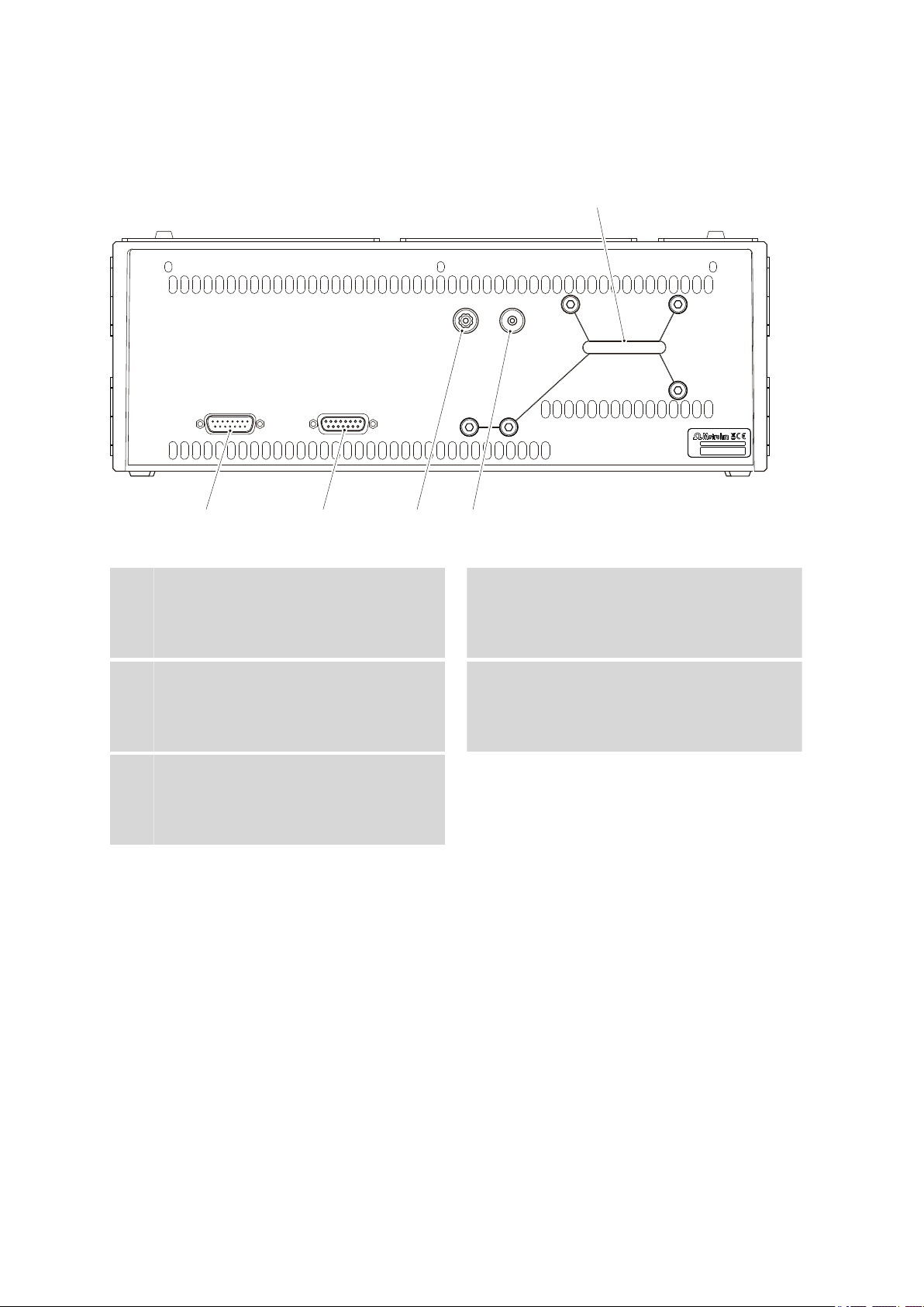
2.2 Rear
Vacuum
Exhaust
Made by Metrohm Herisau Switzerland
Out
In
Transport locking screws
1
2
3
4
5
2.2 Rear
■■■■■■■■■■■■■■■■■■■■■■
Figure 2 Rear 872 Extension Module IC Module
Connector In
1
To connect the extension module to the IC
instrument or to a previous extension module.
Connector Vacuum
3
For connecting further degassing chambers
in extension modules (labeled with Vac-
uum).
Transport locking screws
5
For securing the high pressure pump and
the vacuum pump when transporting the
instrument.
Connector Out
2
To connect an additional extension module.
Waste air opening
4
For extracting the air from the vacuum
chamber (labeled with Exhaust).
■■■■■■■■
8
872 Extension Module IC Module
Page 17

■■■■■■■■■■■■■■■■■■■■■■
3 Assembly
3.1 General
3 Assembly
The extension modules are fitted directly to the 850 Professional IC instrument and connected with it via 6.2156.060 connection cable. Extension
modules have no power supply of their own, but rather draw the electricity they require from the instrument with which they are connected.
Up to three extension modules can be connected to an 850 Professional
IC instrument. The following restrictions are to be taken into account:
Restrictions
The 850 Professional IC instruments and their extension modules must not
have more than 4 identical components in common, i.e.:
■ a maximum of 4 high pressure pumps,
■ a maximum of 4 peristaltic pumps,
■ a maximum of 4 injection valves,
■ a maximum of 4 suppressors (MSM, SPM incl.),
BUT
■ only a maximum of 3 degassers
■ and a maximum of 3 CO
suppressors (MCS)
2
Note
If all 4 high pressure pumps are being used at once, then not all of
them are permitted to run at maximum flow for longer periods of time.
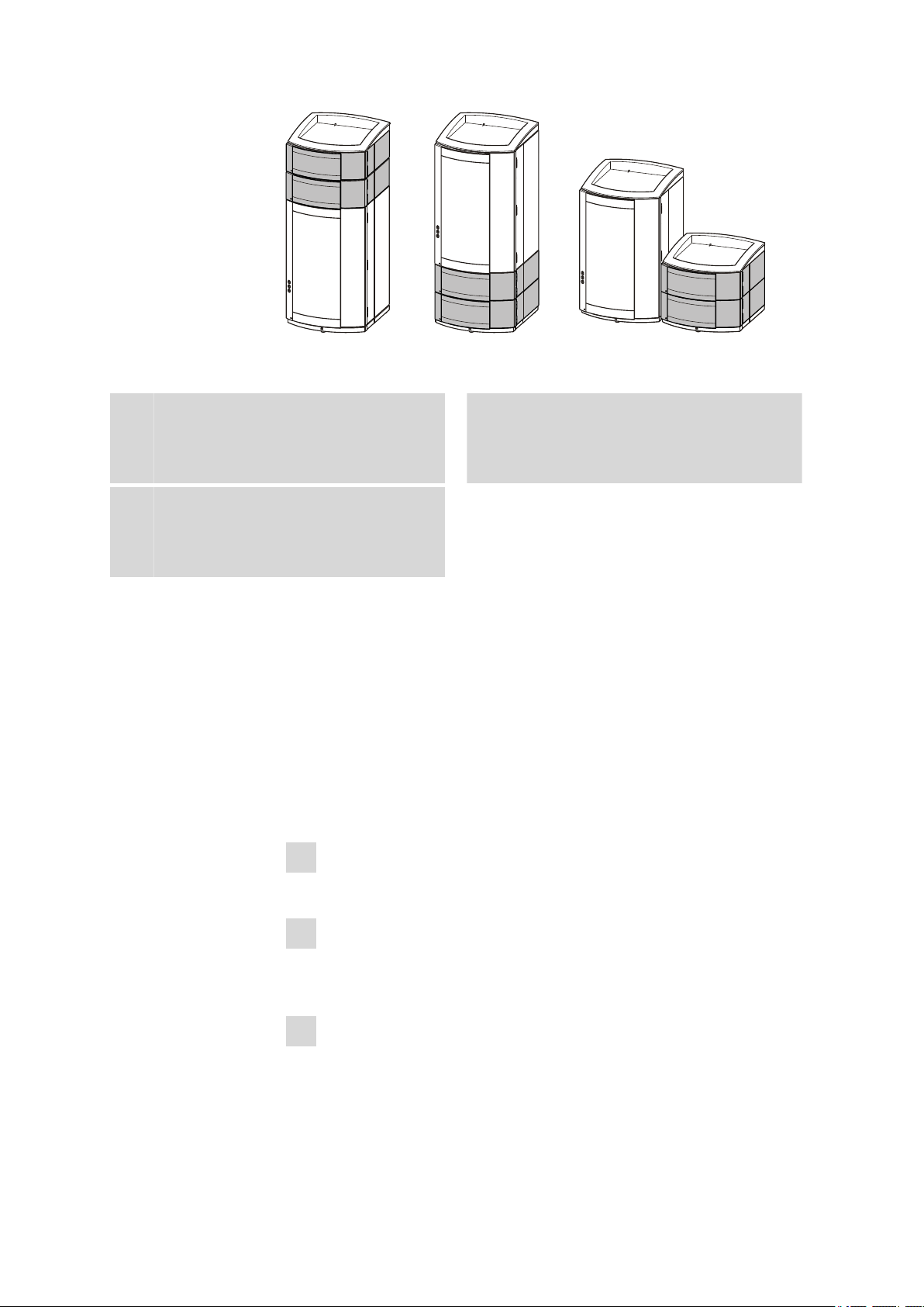
Extension modules can be mounted in the following setup versions:
■ above, between instrument and bottle holder (3-A), or
■ below, between instrument and base tray (3-B), or
■ next to the instrument (3-C) with a separate 6.2061.110 base tray and
a 6.2061.100 bottle holder (to be ordered additionally). For this, the
longer 6.2156.070 connection cable (to be ordered additionally), is
necessary, too.
872 Extension Module IC Module
■■■■■■■■
9
Page 18
3.2 Mounting the extension module onto the IC instrument
A B
C
Figure 3 Setup versions
■■■■■■■■■■■■■■■■■■■■■■
Extension module above the IC instru-
A
ment
Between the 850 Professional IC and the
bottle holder.
Extension module next to the IC instru-
C
ment
With its own base plate and its own bottle
holder next to the 850 bottle holder.
Extension module on the below the IC
B
instrument
Between the base plate and the 850 Profession IC.
Position the extension module in such a way that the capillary connections
can be kept as short as possible. If several extension modules are used,
then they should all be installed in the same location if possible – either
above, below or next to the IC instrument. If this is not possible, then the
extension modules that are located at greater distances from one another
must be connected with one another by means of the longer 6.2156.070
connection cable (available as optional accessory).
3.2 Mounting the extension module onto the IC instrument
■■■■■■■■
10
1
Switching off the IC instrument
Switch the IC instrument off and disconnect the mains cable.
2
Clearing the bottle holder
If there are bottles and other items on the bottle holder, remove
them.
3
Removing drainage tubings
Loosen the drainage tubing from the drainage tubing connector on
the bottle holder.
872 Extension Module IC Module
Page 19
■■■■■■■■■■■■■■■■■■■■■■
1
2
1
2
4
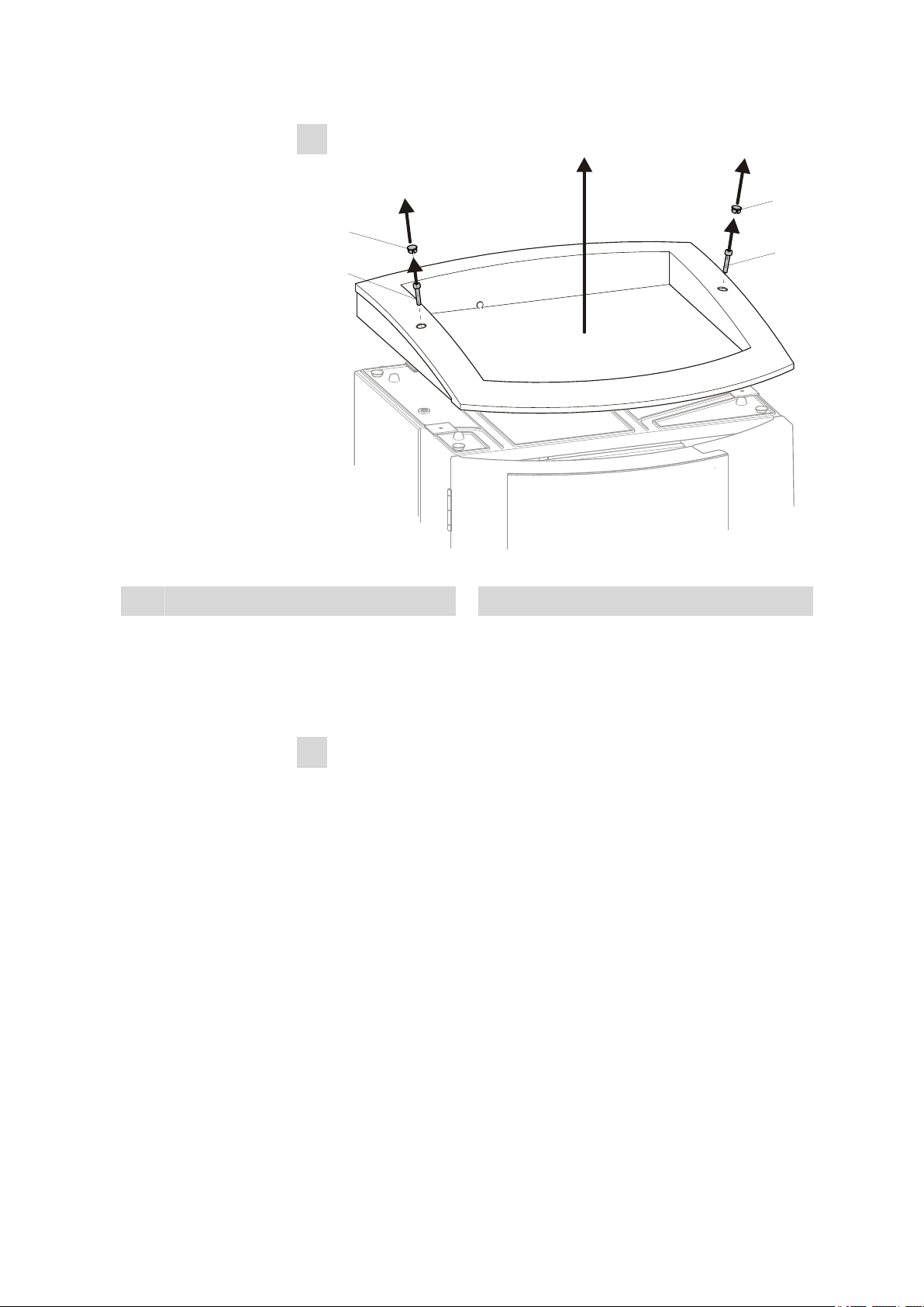
Dismounting the bottle holder
3 Assembly
Figure 4 Dismounting the bottle holder
Cover stoppers
1
■ Remove covering stoppers (4-1).
■ Loosen the cylinder screws with a 6.2621.100 3 mm hexagon
Cylinder screws
2
key.
■ Remove the bottle holder
5
Attaching the extension module(s)
Place the extension module(s) on the IC instrument.
872 Extension Module IC Module
■■■■■■■■
11
Page 20
3.2 Mounting the extension module onto the IC instrument
1
2
1
2
6
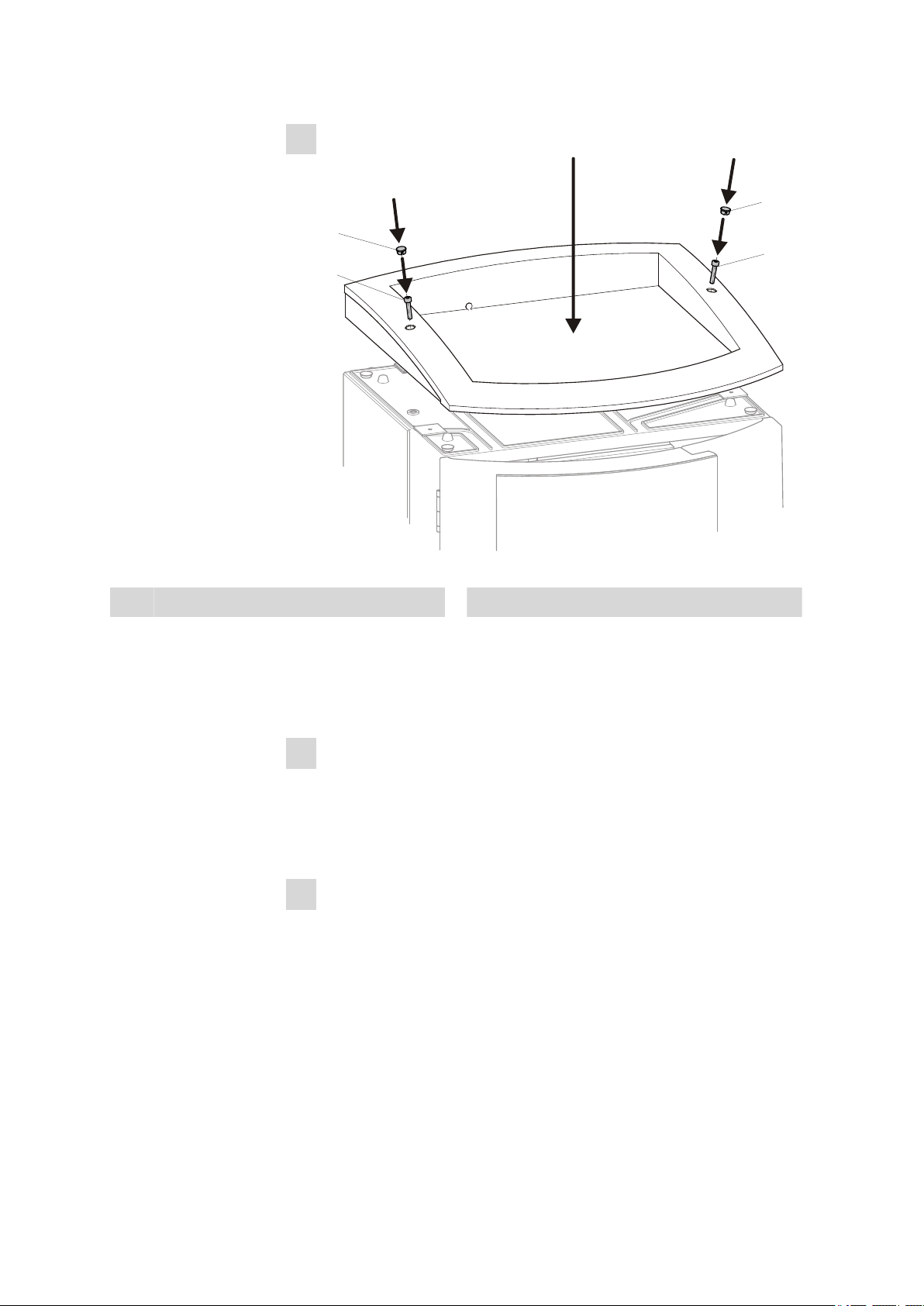
Mounting the bottle holder
■■■■■■■■■■■■■■■■■■■■■■
Figure 5 Mounting the bottle holder
Cover stoppers
1
■ Attach the bottle holder on the extension module.
■ Tighten the cylinder screws (4-2) with an 6.2621.100 3 mm hexa-
Cylinder screws
2
gon key
■ Insert covering stoppers (4-1).
7
Connecting the extension module
■ Plug a 6.2156.060 cable into the connector In of the extension
module and screw it tight.
■ Plug the other end of the cable into the Extension module con-
nector of the IC instrument and screw it tight.
8
Optional: Connecting a further extension module
■ Plug the cable 6.2156.060 or a longer 6.2156.070 cable (optional
accessory) into the connector In of the second extension module
and screw it tight.
■ Plug the other end of the cable into the Out connector of the first
extension module and screw it tight.
■■■■■■■■
12
872 Extension Module IC Module
Page 21

■■■■■■■■■■■■■■■■■■■■■■
9
Mounting the drainage tubing
3 Assembly
Reconnect the drainage tubing to the drainage tubing connector of
the bottle holder.
Possibly, a longer section of silicone tubing 6.186.020 must be cut to
fit and mounted (see also the manual for the IC instrument).
3.3 Mounting the extension module below the IC instrument
1
Switching off the IC instrument
Switch the IC instrument off and disconnect the mains cable.
2
Clearing the bottle holder
If there are bottles and other things on the bottle holder, remove
them.
3
Disconnecting all connections on the rear of the instrument
■ Disconnect the mains cable,
■ Disconnect the MSB cable,
■ Disconnect the USB cable,
■ Disconnect the leak sensor,
■ Remove the drainage tubings.
4
Removing the detector(s)
Disconnect the detector cable(s) and remove the detector(s) from the
IC instrument (see manual for the IC instrument).
5
Removing the base tray
■ Tilt the IC instrument sideways and lay it down flat.
■ Loosen the cylinder screws with a 6.2621.100 3 mm hexagon
key.
■ Remove base tray.
872 Extension Module IC Module
■■■■■■■■
13
Page 22
3.3 Mounting the extension module below the IC instrument
1
2
2
■■■■■■■■■■■■■■■■■■■■■■
1
Base tray
Figure 6 Removing the base tray
Cylinder screws
2
With washer.
6
Mounting the base tray
■ Tilt the extension module sideways and lay it down flat.
■ Attach base tray.
■ Slide the washers onto the cylinder screws (7-2) and tighten these
with a 3 mm hexagon key (6.2621.100).
■■■■■■■■
14
872 Extension Module IC Module
Page 23

■■■■■■■■■■■■■■■■■■■■■■
1
2
2
3 Assembly
1
Base tray
Figure 7 Mounting the base tray
Cylinder screws
2
With washer.
■ Set up the extension module.
■ Optional: Set up further extension modules.
■ Set up the IC instrument.
7
Connecting the extension module
■ Plug a 6.2156.060 cable into the connector In of the extension
module and screw it tight.
■ Plug the other end of the cable into the Extension module con-
nector of the IC instrument and screw it tight.
8
Optional: Connecting a further extension module
■ Plug the cable 6.2156.060 or a longer 6.2156.070 cable (optional
accessory) into the connector In of the second extension module
and screw it tight.
■ Plug the other end of the cable into the Out connector of the first
extension module and screw it tight.
872 Extension Module IC Module
■■■■■■■■
15
Page 24

3.4 Setting up the extension module next to the IC instrument
9
Inserting the detector(s) again and connecting it (them)
■■■■■■■■■■■■■■■■■■■■■■
See manual for the IC instrument.
10
Restoring the loosened connections
■ Reconnect the drainage tubings,
Possibly, a longer section of silicone tubing 6.186.020 must be
cut to fit and mounted (see also the manual for the IC instru-
ment).
■ Connect the leak sensor (see manual for the IC instrument),
■ Connect the USB cable,
■ Connect the MSB cable,
■ Plug in the mains cable.
3.4 Setting up the extension module next to the IC
instrument
1
Switching off the IC instrument
Switch the IC instrument off and disconnect the mains cable.
2
Mounting the base tray
■ Tilt the extension module sideways and lay it down flat.
■ Attach base tray.
■ Tighten the washers and the cylinder screws (8-2) with a 3 mm
hexagon key (6.2621.100).
■■■■■■■■
16
872 Extension Module IC Module
Page 25
■■■■■■■■■■■■■■■■■■■■■■
1
2
2
3 Assembly
1
Base tray
Figure 8 Mounting the base tray
Cylinder screws
2
With washer.
■ Set up the extension module.
■ Optional: Set up further extension modules.
872 Extension Module IC Module
■■■■■■■■
17
Page 26

3.4 Setting up the extension module next to the IC instrument
1
2
1
2
3
Mounting the bottle holder
■■■■■■■■■■■■■■■■■■■■■■
Figure 9 Mounting the bottle holder
Cover stoppers
1
■ Place the bottle holder on the extension module.
■ Tighten the cylinder screws (9-2) with an 6.2621.100 3 mm hexa-
Cylinder screws
2
gon key.
■ Insert covering stoppers (9-1).
4
Connecting the extension module
■ Plug a 6.2156.060 cable into the connector In of the extension
module and screw it tight.
■ Plug the other end of the cable into the Extension module con-
nector of the IC instrument and screw it tight.
5
Optional: Connecting a further extension module
■ Plug the cable 6.2156.060 or a longer 6.2156.070 cable (optional
accessory) into the connector In of the second extension module
and screw it tight.
■ Plug the other end of the cable into the Out connector of the first
extension module and screw it tight.
■■■■■■■■
18
872 Extension Module IC Module
Page 27

■■■■■■■■■■■■■■■■■■■■■■
1
2
3
4
5
6
Connecting the leak sensor
■ Plug the 6.2103.170 adapter into the leak sensor connector of
the IC instrument.
■ Connect the leak sensor cable of the IC instrument to the adapter.
■ Connect the leak sensor cable of the extension module to the
adapter.
7
Connecting the drainage tubings
3 Assembly
Figure 10 Connecting the drainage tubings
Drainage tubing connector
1
For draining escaped liquid from the bottle
holder.
872 Extension Module IC Module
Drainage tubing
2
Section of the 6.1816.020 silicon tubing. For
draining escaped liquid from the bottle
holder.
■■■■■■■■
19
Page 28

3.5 Transport locking screws
■■■■■■■■■■■■■■■■■■■■■■
Drainage tubing connection
3
For supplying escaped liquid through the
connected drainage tubing to the leak sensor.
Drainage tubing
5
Section of the 6.1816.020 silicon tubing.
Guides escaped liquid into a waste container.
■ Plug the drainage tubing (10-2) onto the drainage tubing connec-
tor (10-1) of the bottle holder and shorten to required length.
■ Plug the other end of the drainage tubing (10-2) onto the drain-
age tubing connector (10-3) of the base tray.
■ Plug the drainage tubing (10-5) onto the drainage tubing connec-
tor (10-4) and guide the other end into a waste container.
3.5 Transport locking screws
To avoid damage to the high pressure pump and vacuum pump during
transport, the pumps are secured with transport locking screws .
Drainage tubing connector
4
For draining escaped liquid from the base
tray through the connected drainage tubing.
Remove these transport locking screws before the initial start-up.
Removing transport locking screws
Remove all of the transport locking screws with the 6.2621.030 4
1
mm hexagon key and keep them in a safe place.
Warning
In order to avoid damage to the pump, the transport locking screws
must be remounted each time the instrument undergoes major transport.
■■■■■■■■
20
872 Extension Module IC Module
Page 29

■■■■■■■■■■■■■■■■■■■■■■
4 Installation
4.1 About this chapter
The Installation chapter contains
■ this overview
■ a brief set of instructions for the installation of the 872 Extension Mod-
ule IC Module (see Chapter 4.2, page 21). At each step you will find
cross-references to more detailed installation instructions for individual
components, should you require such aids.
■ an installation diagram (see Chapter 4.3, page 22), showing a com-
pletely installed instrument.
■ several chapters with detailed installation instructions for all compo-
nents, including those that are already installed at the time the instrument is delivered.
4 Installation
4.2 Installation overview
Note
A number of the capillary connections are already connected at the
time the instrument is delivered.
The following work steps must still be carried out:
Installing 872 Extension Module IC Module
1
Installing the eluent path
■ Tighten the clamping screw of the 6.1834.080 eluent aspiration
tubing to the eluent degasser input.
Equip the free end of the eluent aspiration tubing (11-1) and connect it to the eluent bottle (see Chapter 4.4, page 23).
■ Tighten one end of the 6.1831.010 PEEK capillary with a
6.2744.014 PEEK pressure screw to the connector 4 of the injection valve (see Chapter 4.9.1, page 35).
Shorten to required length with the capillary cutter and with the
aid of a 6.2744.040 coupling and two 6.2744.010 pressure
screws connect to the column outlet capillary in the IC instrument.
872 Extension Module IC Module
■■■■■■■■
21
Page 30

4.3 Installation diagram
■■■■■■■■■■■■■■■■■■■■■■
Note
The separation column must not be connected to the system
before having it started up for the first time (see manual for the IC
instrument).
2
Installing the sample path
■ Connect one end of the 6.1803.040 PTFE capillary (11-3) with a
6.2744.014 PEEK pressure screw to connector 1 of the injection
valve (see Chapter 4.9.1, page 35).
Guide the other end through a suitable capillary feed-through out
of the extension module to the Sample Processor and connect it
there (see Sample Processor manual).
■ Connect one end of the second 6.1803.040 PTFE capillary (11-4)
with a 6.2744.014 PEEK pressure screw to connector 2 of the
injection valve.
Guide the other end through a capillary feed-through out of the
extension module to a waste container and fasten it there.
3
Putting the extension module into operation
See Chapter 5, Page 39
■ Putting the extension module into operation together with the IC
instrument (see chapter Start-up in the manual for the IC instrument).
■ Deaerate the high pressure pump at the same time (see Chapter
4.6.2, page 31).
4.3 Installation diagram
Figure 11 Installation diagram shows the capillary connections of the 872
Extension Module IC Module as an additional IC Module which can be
integrated into any existing system.
The arrangement of the modules in the diagram corresponds to the front
view of the extension module.
A few of the capillaries are already pre-installed at the time the instrument
is delivered. Capillaries on which nothing needs to be done at the time of
initial installation are not numbered in the diagram.
■■■■■■■■
22
872 Extension Module IC Module
Page 31

■■■■■■■■■■■■■■■■■■■■■■
Eluent
Degasser
In
Out
Sample
Eluent
Standard
1
2
3
4
5
6
1 2
3
4
Figure 11 Installation diagram
4 Installation
Eluent aspiration tubing 6.1834.080
1
Connected to the eluent degasser. Connect
the other end to the eluent bottle.
Sample aspirating capillary 6.1803.040
3
The following chapters describe the individual installation steps in detail.
4.4 Eluent
4.4.1 Connecting eluent bottle
The eluent is aspirated out of the eluent bottle via the eluent aspiration
tubing (12-1).
The eluent aspiration tubing is connected to the eluent degasser (see
Chapter 4.5, page 27). The tubing must be threaded through a suitable
capillary feed-through of the instrument before the other end can be
equipped.
You will require the parts from the following accessories for equipping the
eluent aspiration tubing:
■ 6.1602.160 Eluent bottle attachment GL 45
■ 6.2744.210 tubing adapter for aspiration filter
■ 6.2821.090 aspiration filter
Eluent connection capillary 6.1831.010
2
Sample outlet capillary 6.1803.040
4
872 Extension Module IC Module
To equip the eluent aspiration tubing proceed as follows:
Assembling eluent aspiration tubing
Guide the free end of the eluent aspiration tubing (12-1) out of the
1
instrument through a suitable capillary feed-through.
■■■■■■■■
23
Page 32

4.4 Eluent
1 2
3
4
■■■■■■■■■■■■■■■■■■■■■■
2
Installing eluent bottle attachment 6.1602.160
■ Slide tubing nipple (12-2) and O-ring (12-3) onto the eluent aspi-
ration tubing (12-1).
■ Push eluent aspiration tubing (12-1) through the bottle attach-
ment (12-4) and screw tight.
Figure 12 Installing eluent bottle attachment
Eluent aspiration tubing 6.1834.080
1
O-ring
3
From accessories set 6.1602.160.
3
Filter holder
1
From accessories set 6.2744.210.
Tubing nipple
2
From accessories set 6.1602.160.
Bottle attachment
4
From accessories set 6.1602.160.
Mounting aspiration filter
■ Insert filter holder (13-1) into the aspiration filter (13-2) and screw
tight.
Figure 13 Mounting aspiration filter
Aspiration filter 6.2821.090
2
■■■■■■■■
24
872 Extension Module IC Module
Page 33

■■■■■■■■■■■■■■■■■■■■■■
3
4
5
4
Install tubing weighting and aspiration filter
Figure 14 Install tubing weighting and aspiration filter
4 Installation
Eluent aspiration tubing 6.1834.080
1
Tubing weighting
3
From accessories set 6.2744.210.
Aspiration filter 6.2821.090
5
With filter holder from accessories set
6.2744.210.
■ Slide the tubing weighting (14-3) onto the eluent aspiration tub-
■ Slide the clamping screw (14-4) onto the eluent aspiration tubing
■ Insert the eluent aspiration tubing (14-1) into the aspiration filter
■ Screw together clamping screw (14-4) and filter holder (13-1).
Eluent bottle attachment 6.1602.160
2
Clamping screw
4
From accessories set 6.2744.210.
ing (14-1).
(14-1).
(14-5). The end of the tubing should approximately reach to the
center of the aspiration filter.
Figure 15
872 Extension Module IC Module
Eluent aspiration tubing fully equipped.
5
Mounting eluent aspiration tubing to the eluent bottle
■ Insert the eluent aspiration tubing into the eluent bottle (16-10).
■■■■■■■■
25
Page 34

4.4 Eluent
1
1
2
3
4
5
6
7
89
10
11
12
13
14
■■■■■■■■■■■■■■■■■■■■■■
■ Fasten the completely equipped bottle attachment (16-10) on the
eluent bottle. The aspiration filter (16-6) must rest on the base of
the eluent bottle.
■ Close the remaining small opening on the bottle attachment with
a threaded stopper from the accessories set.
6
Mounting the adsorber tube
Note
In the case of alkaline eluents and eluents with lower buffer
capacity, the eluent bottle must be equipped with a CO2 adsorber
(16-4).
■ First, place a piece of cotton (16-3), then the CO
adsorber (16-4)
2
in the large opening of the adsorber tube (16-2) and close with
the plastic cover.
■ Fasten the adsorber tube (16-2) using the SGJ clip (16-12) onto
the bottle attachment (16-11).
26
Eluent aspiration tubing 6.1834.080
1
For aspirating the eluent. Pre-installed.
■■■■■■■■
Figure 16
Eluent bottle – connected
Adsorber tube 6.1609.000
2
872 Extension Module IC Module
Page 35

■■■■■■■■■■■■■■■■■■■■■■
4 Installation
Wadding
3
Eluent
5
Filter holder
7
From accessories set 6.2744.210.
Tubing weighting
9
From accessories set 6.2744.210.
Bottle attachment 6.1602.160
11
Tubing nipple
13
4.5 Eluent degasser
Gas bubbles in the eluent lead to an unstable baseline, as high pressure
pumps can transport liquids, but not gases. The eluent therefore has to be
degassed, before it reaches the high pressure pump.
The eluent degasser removes gas bubbles and dissolved gases from the
eluent. For degassing, the eluent flows into a vacuum chamber through a
special fluoropolymer capillary.
CO2 adsorber
4
Adsorbs CO2 from the air (e.g. Merck soda
lime with indicator, no. 6839.10).
Aspiration filter 6.2821.090
6
Clamping screw
8
From accessories set 6.2744.210.
Eluent bottle 6.1608.070
10
SGJ clip 6.2023.020
12
Threaded stopper
14
Note
The eluent degasser is already installed in the newly delivered instrument. The following installation instructions must only be followed, if
the connections to the degasser had to be disconnected for maintenance.
872 Extension Module IC Module
■■■■■■■■
27
Page 36

4.5 Eluent degasser
5
6
1
3
4
■■■■■■■■■■■■■■■■■■■■■■
Connecting the eluent degasser
Figure 17 Eluent degasser
Eluent degasser input
1
Tubing flare
3
With tubing nipple.
Eluent aspiration tubing (6.1834.080)
5
For aspirating the eluent. The clamping
screw (17-4) is firmly mounted.
1
■ Insert the eluent aspiration tubing (17-5) into the eluent degasser
■ Carefully tighten the clamping screw (17-4).
■ Insert connection capillary (17-6) (the end with the longer clamp-
2
■ Carefully tighten the clamping screw (17-4).
■ Connect the other end of the connection capillary (17-6) (with
Eluent degasser output
2
Clamping screw
4
Connection tubing (6.1834.090)
6
Connection from the eluent degasser to the
high pressure pump (see Chapter 4.6, page
29). The clamping screw (17-4) is firmly
mounted.
Caution
The clamping screws (17-4) must be tightened carefully. Use the
wrench (6.2621.050) to do this.
input (17-1).
ing screw (17-4)) into the eluent degasser output (17-2).
the shorter clamping screw ) to the high pressure pump (18-9)
(see "Connecting inlet to the high pressure pump", page 30).
■■■■■■■■
28
872 Extension Module IC Module
Page 37

■■■■■■■■■■■■■■■■■■■■■■
10
8
9
1
2
3
4
5
6
2
7
2
2
2
11
2
12
2
13
4.6 High pressure pump
The intelligent and low pulsation high pressure pump pumps the eluent
through the system. It is equipped with a chip on which its technical specifications and "life history" (operating hours, service data, ... ) are saved.
The purge valve is used for deaerating (see Chapter 4.6.2, page 31) the
high pressure pump.
4.6.1 Capillary connections high pressure pump/purge valve
Note
All of the capillary connections of the high pressure pump and the
purge valve are already installed in the newly delivered instrument.
4 Installation
Connection capillary
1
PEEK capillary, connects main piston and
auxiliary piston.
Outlet valve holder
3
872 Extension Module IC Module
Figure 18
Capillary connections high pressure pump/purge valve
PEEK pressure screw, short 6.2744.070
2
Pump head 6.2824.110
4
■■■■■■■■
29
Page 38

4.6 High pressure pump
5
1
2
3
4
■■■■■■■■■■■■■■■■■■■■■■
Fastening screws
5
For fastening the pump head.
Pump head input capillary
7
PEEK capillary at the input of the pump
head.
Coupling
9
For the connection of the eluent path at the
input of the high pressure pump. Can be
ordered together with the pressure screw
(18-8) under the number 6.2744.230.
Purge valve
11
For deaerating the high pressure pump.
With rotary knob in the center and pressure
sensor.
Connection capillary
13
Connects the output of the pump head with
the purge valve.
Note
Inlet valve holder
6
Pressure screw
8
For connecting a PEEK capillary to the coupling (18-9).
Deaerating capillary
10
For aspirating the eluent when deaerating
the high pressure pump (see Chapter 4.6.2,
page 31).
Connection capillary
12
For connecting the inline filter (see Chapter
4.7, page 33)
The eluent aspiration tubing is already installed in the newly delivered
instrument. The following installation instructions need not be carried
out at the time of initial installation.
Connecting inlet to the high pressure pump
Figure 19
Pressure screw
1
For connecting the coupling (19-2) to the
pump head input capillary (18-7).
Can be ordered together with the coupling
under the number 6.2744.230.
High pressure pump – Connect inlet
Coupling 6.2744.230
2
For connecting the eluent aspiration tubing
(19-4) to the input of the high pressure
pump.
■■■■■■■■
30
872 Extension Module IC Module
Page 39

■■■■■■■■■■■■■■■■■■■■■■
4 Installation
Clamping screw
3
Backup ring
5
Eluent aspiration tubing
4
Eluent aspiration tubing 6.1834.080 or
6.1834.090.
1
Connecting coupling
Fasten the coupling (19-2) with a pressure screw (19-1) on the pump
head input capillary (18-7).
2
Connecting eluent aspiration tubing
Caution
The clamping screws must be tightened carefully. To tighten, grip
the coupling (19-2) with the 6.2739.000 key and grip the clamping screw (19-3) with the 6.2621.050 wrench.
■ Plug the eluent aspiration tubing (19-4) into the coupling (19-2).
■ Tighten clamping screw (19-3).
4.6.2 Deaerating the high pressure pump
The high pressure pump will only operate perfectly if the pump head contains no more air bubbles. Therefore it must be deaerated during initial
start-up and after every change of eluent.
Caution
The high pressure pump must not be deaerated before the initial startup .
Deaerate the high pressure pump as follows (see Figure 20, page 32):
Deaerating the high pressure pump
The instrument must be connected to the PC and switched on to deaerate
the high pressure pump.
872 Extension Module IC Module
■■■■■■■■
31
Page 40

4.6 High pressure pump
5
1
2
6
7
5
3
4
5
■■■■■■■■■■■■■■■■■■■■■■
Figure 20 Deaerating the high pressure pump
Syringe 10 mL 6.2816.020
1
For aspirating the eluent.
Purging needle 6.2816.040
3
PEEK pressure screws, short
5
6.2744.070
Purge valve rotary knob
7
Luer connector
2
On purging needle.
Deaerating capillary
4
Purge valve
6
1
Connecting the purging needle
■ Push the end of the purging needle (20-3) over the end of the
deaerating capillary (20-4) on the purge valve.
2
Connecting the syringe
■ Insert syringe (20-1) in the Luer connector (20-2) of the purging
needle (see Figure 20, page 32).
3
Opening purge valve
■ Open the rotary knob (20-7) by approx. ½ rotation counterclock-
wise.
4
Setting the flow rate
■ Start MagIC Net (if not yet started).
■ Ensure that the eluent aspiration tubing is immersed sufficiently in
the eluent.
■ Let the high pressure pump run.
■■■■■■■■
32
872 Extension Module IC Module
Page 41

■■■■■■■■■■■■■■■■■■■■■■
5
6
4.7 Inline filter
Between the purge valve and the pulsation damper the 6.2821.120 inline
filter is installed as protection against particles.
Inline filters protect the separation column securely against possible contamination from the eluent. Inline filters can however also just as well be
used for the purpose of protecting the suppressor against contaminations
in the regeneration or rinsing solutions. The fine 2 µm material of the
readily and easily replaceable filter platelets removes particles such as bacteria and algae from the solutions.
4 Installation
Aspirating eluent
■ Aspirate with the syringe (20-1) until bubble-free eluent flows into
the syringe.
Completing deaerating
■ Turn off high pressure pump.
■ Close rotary knob (20-7).
■ Remove syringe (20-1) from the Luer connector (20-2).
■ Pull the purging needle (20-3) out of the deaerating capillary
(20-4).
Note
The inline filter is already installed in the newly delivered instrument.
The following installation instructions need not be carried out at the
time of initial installation.
Installing the inline filter
Caution
Observe the flow direction marked on the filter housing for the connection of the inline filter.
872 Extension Module IC Module
■■■■■■■■
33
Page 42

4.8 Pulsation damper
2 3
2 4
1
Figure 21 Connecting inline filter
■■■■■■■■■■■■■■■■■■■■■■
Connection capillary
1
Connects the purge valve with the inline filter
Inline filter 6.2821.120
3
Protects against particles.
Screw on the connection capillary running from the purge valve with
1
a 6.2744.070 pressure screw to the input side of the inline filters.
Screw on the connection capillary running to the pulsation damper
2
with a 6.2744.070 pressure screw to the output side of the inline filter.
4.8 Pulsation damper
Note
PEEK pressure screws, short
2
6.2744.070
Connection capillary
4
Connects the inline filter with the pulsation
damper.
■■■■■■■■
34
The pulsation damper is already installed in the newly delivered instrument.
Caution
The pulsation damper is maintenance-free and may not be opened.
The pulsation damper protects the separation column from damage
caused by pressure fluctuations when switching the injection valve, and
reduces interfering pulsations during highly sensitive measurements. In
order to ensure these functionalities, it must be connected between the
high pressure pump (see Chapter 4.6, page 29) and injection valve (see
Chapter 4.9, page 35).
The pulsation damper can be operated in both directions.
872 Extension Module IC Module
Page 43

■■■■■■■■■■■■■■■■■■■■■■
3
4
5
2
3
6
1
2
4 Installation
Figure 22 Pulsation damper – Connection
Connection capillary
1
Connection to the inline filter.
PEEK pressure screws, short
3
6.2744.070
Pulsation damper 6.2620.150
5
Fastening screws
2
Holder for pulsation damper
4
Connection capillary
6
Connection to the injection valve.
4.9 Injection valve
The injection valve connects the eluent and sample path. Through rapid
and precise valve switchover a precise amount of sample solution defined
by the size of the sample loop is injected and rinsed with eluent onto the
separation column.
4.9.1 Connecting the injection valve
The injection valve has six connectors: two for the sample path (connectors 1 and 2), two for the eluent path (connectors 4 and 5) and two for
the sample loop (connectors 3 and 6).
Note
The capillaries of the eluent path and the sample path and the sample
loop are already installed in the newly delivered instrument.
872 Extension Module IC Module
■■■■■■■■
35
Page 44

4.9 Injection valve
1
2
3
4
5
6
2
4
5
7
7
■■■■■■■■■■■■■■■■■■■■■■
Figure 23 Injection valve – connected
Injection valve
1
Connection capillary
3
Connected to connector 4. Carries eluent to
the injection valve.
Connection capillary
5
Connected to connector 1. Carries sample to
the injection valve.
PEEK pressure screw 6.2744.010
7
Replacing the sample loop
The sample loop can be replaced, depending on requirements. For additional information concerning selection of the appropriate sample loop,
see Chapter 4.9.3, page 38.
Use only 6.2744.010 PEEK pressure screws for connecting capillaries
and sample loop to the injection valve.
Note
Sample loop
2
Connected to connectors 3 and 6.
Connection capillary (column inlet
4
capillary)
Connected to connector 5. Carries eluent to
the separation column.
Connection capillary
6
Connected to connector 2. Carries sample to
the waste container.
■■■■■■■■
36
1
Removing existing sample loop
■ Loosen 6.2744.010 pressure screws at connector 3 and connec-
tor 6.
■ Remove sample loop.
2
Mounting new sample loop
■ Fasten one end of the sample loop (23-2) with a 6.2744.010
PEEK pressure screw (23-7) to connector 3.
■ Fasten the other end of the sample loop (23-2) with a second
6.2744.010 PEEK pressure screw (23-7) to connector 6.
872 Extension Module IC Module
Page 45

■■■■■■■■■■■■■■■■■■■■■■
12
4 5
3 6
12
4 5
3 6
1
2
4
3
5
4
3
1
2
A B
4.9.2 Mode of operation of the injection valve
The injection valve (see Figure 24, page 37) can adopt two valve positions - FILL and INJECT. Switching back and forth between the two valve
positions determines whether the sample path or the eluent path is guided through the sample loop. The following figure provides a schematic
display of the flow paths of the two valve positions.
4 Installation
Figure 24 Injection valve – Positions
Position FILL
A
Eluent input
1
Capillary coming from the high pressure
pump.
Sample input
3
Sample aspirating capillary.
Sample loop
5
Position INJECT
B
Eluent output
2
Capillary to the column.
Sample output
4
Capillary to waste container.
Position A In the position FILL, the sample solution flows
through the sample loop to the waste container.
The eluent flows directly to the separation column at the same time.
Position B In the position INJECT, the eluent flows through
the sample loop to the separation column. If
sample solution is to be found in the sample
loop at the time of the valve switchover, then
this will be conveyed along with the eluent, thus
making its way to the separation column. The
flow in the sample path is either stopped or the
sample flows directly to the waste container.
872 Extension Module IC Module
■■■■■■■■
37
Page 46

4.9 Injection valve
4.9.3 Selecting the sample loop
The amount of sample solution injected depends on the volume of the
sample loop. The choice is made on the basis of the application. The following sample loops are normally used:
Cation determination 10 µL
Anion determination with suppression 20 µL
Anion determination without suppression 100 µL
■■■■■■■■■■■■■■■■■■■■■■
■■■■■■■■
38
872 Extension Module IC Module
Page 47

■■■■■■■■■■■■■■■■■■■■■■
5 Set to work
The extension module is put into operation together with the IC instrument.
Putting IC instrument into operation with extension modules
1
2
3
4
5
5 Set to work
Start MagIC Net.
Connect the 872 Extension Module to the 850 Professional IC.
Connect the 850 Professional IC instrument to the PC and switch on.
The extension module is recognized automatically by MagIC Net.
Follow the other instructions in the chapter Initial start-up of the
manual for the 850 Professional IC.
Deaerate the high pressure pump at the same time (see Chapter
4.6.2, page 31).
872 Extension Module IC Module
■■■■■■■■
39
Page 48

6.1 General information
6 Operation and maintenance
6.1 General information
6.1.1 Care
Warning
The instrument housing must not be opened by untrained personnel.
The instrument requires appropriate care. Excess contamination of the
instrument may result in functional disruptions and a reduction in the service life of the sturdy mechanics and electronics.
Caution
■■■■■■■■■■■■■■■■■■■■■■
Although this is prevented to a great extent by design measures, the
mains plug should be unplugged immediately if aggressive media has
penetrated the inside of the instrument, so as to avoid serious damage
to the instrument electronics. In such cases, the Metrohm Service must
be informed.
Spillages of chemicals and solvents should be cleaned up immediately. In
particular, the plug connections on the rear panel of the instrument (especially the mains plug) should be protected from contamination.
6.1.2 Maintenance by Metrohm Service
Maintenance of the instrument is best carried out as part of an annual
service, which is performed by specialist personnel from Metrohm. If
working frequently with caustic and corrosive chemicals, a shorter maintenance interval is recommended. The Metrohm service department offers
every form of technical advice for maintenance and service of all Metrohm
instruments.
6.1.3 Operation
Caution
■■■■■■■■
40
In order to avoid disturbing temperature influences, the entire system
must be protected against direct sunlight.
872 Extension Module IC Module
Page 49

■■■■■■■■■■■■■■■■■■■■■■
6.1.4 Shutting down
If the instrument is shut down for a longer period of time, the entire IC
system must be rinsed as follows to rid it of salts in order to prevent eluent salts from forming crystals which may cause subsequent damage.
■ rinse all capillaries and the Dosino with methanol/ultra pure water
(1:4),
■ rinse all pump tubings of the peristaltic pump with ultra pure water.
6.2 Door
The door is made of PMMA (polymethylmetacrylate). It must never be
cleaned with abrasive media or solvents.
6 Operation and maintenance
Caution
Caution
6.3 Eluent
6.3.1 Production
The chemicals used for the production of eluents should have a degree of
purity of at least "p.a.". Only ultra pure water (resistance > 18.2 MΩ *cm)
may be used for dilution (this generally applies for reagents which are
used in ion chromatography).
Newly produced eluents should always be microfiltered (filter 0.45 µm).
The composition of the eluent has a crucial effect on the chromatographic
analysis:
Concentration An increase in the concentration generally leads
Never use the door as a handle.
Caution
Only microfiltered (filter 0.45 µm) eluents may be used.
to shorter retention times and faster separation,
but also to higher background conductivity.
872 Extension Module IC Module
■■■■■■■■
41
Page 50

6.4 High pressure pump
pH pH changes result in shifts in the dissociation
Organic solvents The addition of an organic solvent (e.g. metha-
6.3.2 Operation
6.3.2.1 Supply bottle
The supply bottle with the eluent must be connected as indicated in
ter 4.4.1, page 23. This is above all important for eluents with volatile solvents (e.g. acetone).
Moreover, condensation must also be prevented in the eluent bottle. Drop
formation can change the concentration ratio in the eluent.
■■■■■■■■■■■■■■■■■■■■■■
equilibria and hence changes in the retention
times.
nol, acetone, acetonitrile) to aqueous eluents
generally accelerates lipophilic ions.
chap-
6.3.2.2
6.3.2.3
Aspiration filter
To protect the IC system against foreign particles, we recommend aspirating the eluents via a 6.2821.090 aspiration filter (13-2). This aspiration filter must be replaced should it show signs of yellow discoloration (but no
later than every 3 months).
In the case of very sensitive measurements, the eluent should be stirred
constantly with a magnetic stirrer.
Changing the eluent
When changing the eluent, it must be ensured that no precipitates can
occur. Solutions following one another in direct succession must therefore
be miscible. If the system has to be rinsed organically, several solvents
with rising or falling lipophilia must be used.
6.4 High pressure pump
6.4.1 Protection
Caution
■■■■■■■■
42
The pump head is filled ex works with methanol/ultra pure water. It
must be ensured that the eluent used is freely miscible with the solvent
remaining in the pump head.
To protect the high pressure pump against foreign particles, we recommend that the eluent undergoes a microfiltration (filter 0.45 µm) before
being aspirated via a 6.2821.090 aspiration filter (see "Assembling eluent
aspiration tubing", page 23).
872 Extension Module IC Module
Page 51

■■■■■■■■■■■■■■■■■■■■■■
Salt crystals between the piston and seal cause abrasion particles which
can find their way into the eluent. These lead to contaminated valves, a
rise in pressure and in extreme cases scratched pistons. It is therefore
essential to ensure that no precipitates can occur (see Chapter 6.3.2.3,
page 42).
In order to spare the pump seals, the pump should not be operated dry.
Therefore ensure that the eluent supply is correctly connected and that
there is enough eluent in the eluent bottle each time before turning on
the pump.
6.4.2 Maintenance
6 Operation and maintenance
Caution
Caution
Maintenance work on the high pressure pump may not be carried out
unless the instrument is switched off.
Pump head maintenance
An unstable baseline (pulsation, flow fluctuations) is in many cases the
result of contaminated valves (31-2), (31-3) or defective, leaking piston
seals on the high pressure pump. Proceed as follows for cleaning contaminated valves and/or replacing worn parts such as pistons, piston seal and
valves:
This maintenance work should be carried out at least once a year.
Removing the pump head
Turn off high pressure pump and wait until pressure is released.
1
Loosen the pressure screw on the inlet valve holder (18-2) and
2
unscrew the coupling (18-9), the pump head input capillary (18-7)
and the eluent aspiration tubing from the pump head.
Unscrew the pump head output capillary (18-13) from the pump
3
head.
Remove pump head from the pump housing by loosening the 4 fas-
4
tening screws (18-5) using the 6.2621.030 hexagon key. The main
872 Extension Module IC Module
■■■■■■■■
43
Page 52

6.4 High pressure pump
2
1
■■■■■■■■■■■■■■■■■■■■■■
piston is on the left (viewed from the front), and the auxiliary piston
is on the right.
Cleaning/replacing the zirconium oxide piston
Clean one piston after the other as follows:
1
Removing the piston cartridge from the pump head
Loosen the piston cartridge with a wrench and unscrew from the
pump head by hand.
1
Pump head
Figure 25 Removing piston
Piston
2
2
Dismantle the piston
Caution
On the inside of the piston cartridge there is a taut spring than can
jump out of the piston cartridge if suddenly loosing tension.
When opening the piston cartridge, hold pressure towards the
spring and unscrew carefully.
■ Loosen the screw of the piston cartridge with a wrench and
unscrew carefully by hand and by holding pressure towards the
taut spring.
■ Remove the zirconium oxide piston and lay on a tissue.
■■■■■■■■
44
872 Extension Module IC Module
Page 53

■■■■■■■■■■■■■■■■■■■■■■
1 2
3
4
5 6
7
8
■ Remove the spring retainer, spring and the inner plastic sleeve
from the piston cartridge and lay by.
■ Remove the backup ring from the pump head and lay to the other
parts.
Figure 26 Components of the piston cartridge
6 Operation and maintenance
Piston cartridge screw
1
Zirconium oxide piston with piston
3
shaft
Order number: 6.2824.070.
Spring
5
Order number: 6.2824.060.
Piston cartridge
7
3
4
Retaining washer
2
Spring retainer
4
Inner plastic sleeve
6
Protects from metallic abrasion.
Backup ring
8
Cleaning the components of the piston
■ Clean zirconium oxide pistons contaminated by abrasion or
deposits with pure abrasive cleaning powder, rinse particle free
with ultra pure water and dry.
Replace highly contaminated or scratched zirconium oxide pistons
(spare part: 6.2824.070 zirconium oxide piston).
■ Rinse the other parts of the piston and dry with a lint-free cloth.
Assembling the piston
■ Insert the inner plastic sleeve, spring and spring retainer into the
piston cartridge.
■ Slide the zirconium oxide piston carefully into the piston cartridge
until its tip emerges from the small opening of the piston cartridge.
■ Attach screw and tighten by hand.
872 Extension Module IC Module
■■■■■■■■
45
Page 54

6.4 High pressure pump
2
1
■■■■■■■■■■■■■■■■■■■■■■
Replacing the piston seal
The 6.2617.010 special tool (see Figure 27, page 46) is necessary in
order to remove the piston seal from the pump head. It consists of two
parts: a tip for removing the old piston seal and a sleeve for inserting the
new piston seal.
Figure 27 Tool for piston seal 6.2617.010
Pin
1
Pin for removing the old piston seal.
Sleeve
2
Sleeve for inserting the new piston seal.
Caution
Screwing the 6.2617.010 special tool for the piston seal into the piston
seal destroys this completely!
1
Removing the piston seal
Caution
Avoid touching the sealing surface in the pump head (18-4) with
the tool.
Screw the special tool for the piston seal (27-1) with the narrow side
just as far into the piston seal as the same can be removed.
■■■■■■■■
46
872 Extension Module IC Module
Page 55

■■■■■■■■■■■■■■■■■■■■■■
1
2
1
2
6 Operation and maintenance
Figure 28 Removing the piston seal
Piston seal
1
2
Tool for piston seal 6.2617.010
1
Sleeve for inserting the new piston seal.
Tool for piston seal
2
Pin of the tool.
Inserting the new piston seal into the tool
Insert the new piston seal tightly by hand into the recess of the
sleeve of the tool for the piston seal (27-2). The sealing springs must
be visible from the outside.
Figure 29 Insert the piston seal into the tool
Piston seal
2
Order number: 6.2741.020
872 Extension Module IC Module
3
Inserting the new piston seal into the pump head
Guide the sleeve of the tool for the piston seal (27-2) with inserted
piston seal into the pump head and press the seal with the wide end
of the tool for the piston seal (27-1) into the pump head recess.
■■■■■■■■
47
Page 56

6.4 High pressure pump
1
2
■■■■■■■■■■■■■■■■■■■■■■
Figure 30 Inserting the piston seal into the pump head
4
Replacing the piston cartridge
Screw the assembled piston cartridge back into the pump head and
tighten, first by hand, then additionally by approx. 15° with a
wrench.
Cleaning the inlet valve and outlet valve
1
Removing valves
■ Unscrew the connection capillary for the auxiliary piston (18-1)
from the outlet valve holder.
■ Unscrew the holders for the inlet and outlet valves and remove
valves.
■■■■■■■■
48
872 Extension Module IC Module
Page 57

■■■■■■■■■■■■■■■■■■■■■■
1
2
3
4
6 Operation and maintenance
Figure 31 Removing valves
Outlet valve holder
1
Inlet valve
3
Order number: 6.2824.170
Outlet valve
2
Order number: 6.2824.160
Inlet valve holder
4
2
Cleaning undissected valve
Clean contaminated or blocked valves initially without dismantling
them completely.
■ Rinse the valve in eluent flow and counterflow direction using a
spray bottle filled with ultra pure water, RBS solution or acetone.
■ The rinsing effect is further increased through a short treatment
(lasting for a maximum of 20 s) in an ultrasonic bath.
Note
Longer lasting ultrasonic baths can damage the ruby ball of the
valve.
Only if this cleaning is useless, dismantle the valves separately and
clean the components.
3
Dismantling valve
Dismantle every valve separately.
872 Extension Module IC Module
Note
For dismantling the valve the 6.2617.020 tool for valve cartridges
is required.
■■■■■■■■
49
Page 58

6.4 High pressure pump
1
3
4
2
■■■■■■■■■■■■■■■■■■■■■■
■ Place the valve with the seal faced downwards above the recess
in the holder.
■ Push the valve components out of the valve housing using the
needle of the tool.
Figure 32 Dismantling valve
Needle
1
For pushing the valve components out of
the valve housing.
Holder
3
The components of the valve are collected in the recess of the
holder.
■ The inlet valve and the outlet valve consist of the same, just differ-
Valve
2
Recess
4
For collecting the valve components.
Note
The components of the valve are very small. In order not to lose
them, put the components into a dish.
ently arranged components (see Figure 33, page 51).
■■■■■■■■
50
872 Extension Module IC Module
Page 59

■■■■■■■■■■■■■■■■■■■■■■
1
2
3
5
6
7
8
9
10
9
8
7
10
5
4
6
6 Operation and maintenance
Figure 33 Components of the inlet valve and outlet valve
Inlet valve 6.2824.170
1
Inlet valve housing
3
Sealing ring (black)
5
Sapphire sleeve
7
The shiny side must point to ruby ball.
Ceramic holder for ruby ball
9
4
Clean the components of the valve
Outlet valve 6.2824.160
2
Outlet valve housing
4
Sleeve
6
Ruby ball
8
Seal
10
The larger opening must point outwards.
Rinse the valve components with ultra pure water and/or acetone
and dry with a lint-free cloth.
5
Reassemble the valve
Reassemble valve components according to figure 33, page 51.
■ Insert the seal with the larger opening faced downwards into the
recess of the tool.
■ Lay the other valve components above another in the correct
sequence (see Figure 33, page 51).
872 Extension Module IC Module
■■■■■■■■
51
Page 60

6.4 High pressure pump
■■■■■■■■■■■■■■■■■■■■■■
■ Place the valve housing over the stacked components and hold it
tightly.
■ By tilting the tool, the valve components slide into the valve hous-
ing.
■ Press the seal by hand well on the valve housing.
6
Checking the flow direction
Rinse the valve in the direction of the arrow on the valve housing and
check wether liquid is escaping on the other end.
If this is not the case, the valve has to be dismantled again and be
assembled correctly (see Figure 33, page 51).
7
Inserting the valves back into the pump head
Caution
If by mistake, the inlet valve is mounted instead of the outlet valve,
an extreme pressure builds up within the working cylinder, which
can destroy the piston seal!
When inserting the valves, please take into account that the liquid
is being pumped through the pump head from bottom to top.
■ Insert the inlet valve into the inlet valve holder the way the seal is
visible.
■ Screw the inlet valve holder into the bottom of the pump head
and tighten with a wrench (31-4).
■ Insert the outlet valve into the outlet valve holder the way the seal
is visible.
■ Screw the outlet valve holder into the top of the pump head and
tighten with a wrench (31-1).
■■■■■■■■
52
872 Extension Module IC Module
Page 61

■■■■■■■■■■■■■■■■■■■■■■
1 2 3
4
1
5
5
6 Operation and maintenance
Mounting the pump head
Note
To prevent the pump head from being positioned the wrong way, it is
provided with different bore hole depths for the fastening bolts, i. e. a
fastening bolt is longer than all others. The bore hole with the greatest
depth must therefore be assigned to the longest bolt. If this is not the
case, the pump will not function perfectly.
1
Mount the pump head on the pump again using the four fastening
screws (18-5). Firmly tighten the screws with the 6.2621.030 hexagon key.
Screw connection capillaries (18-1), (18-7) and (18-13) onto the
2
pump head again.
6.5 Inline filter
6.5.1 Maintenance
The 6.2821.120 inline filters comprise the filter housing (34-2), the filter
screw (34-4) and the flter (34-3). New filters (34-3) are available under
the order number 6.2821.130 (10 items).
The 6.2821.130 filters (21-3) should be changed every 3 months (more
frequently at higher backpressure).
Figure 34
1
3
Changing the filter
PEEK pressure screws, short
6.2744.070
6.2821.130 filter
Packaging contains 10 items.
Filter housing
2
Housing of the inline filter. Part of the
6.2821.120 accessories.
Filter screw
4
Screw of the inline filter. Part of the
6.2821.120 accessories.
Connection capillaries
5
872 Extension Module IC Module
■■■■■■■■
53
Page 62

6.5 Inline filter
■■■■■■■■■■■■■■■■■■■■■■
Changing the filter
The flow must be stopped before changing the filter.
1
Removing the inline filter
■ Unscrew the pressure screws (34-1) from the inline filter.
2
Unscrewing the filter screw
■ Screw the filter screw (34-4) out of the filter housing (34-2) with
the aid of two 6.2621.000 adjustable wrenches.
3
Inserting the filter
■ Remove the old filter (34-3) with tweezers.
■ Place the new filter (34-3) flat in the filter housing with tweezers
(34-2).
4
Mounting filter screw
■ Screw the filter screw (34-4) back into the filter housing (34-2)
and tighten by hand. Then additionally tighten slightly with two
6.2621.000 adjustable wrenches.
5
Remounting the inline filter
■ Screw the pressure screws (34-1) back onto the inline filter.
6
Rinsing the inline filter
■ Dismantle the guard column (if present) and the separation col-
umn and replace with a 6.2744.040 coupling.
■ Rinse the instrument with eluent.
■■■■■■■■
54
872 Extension Module IC Module
Page 63

■■■■■■■■■■■■■■■■■■■■■■
6.6 Inline sample preparation
To protect the separation column against foreign particles which can
affect the separating efficiency, we recommend that all samples undergo
a microfiltration (filter 0.45 µm). The ultrafiltration cell can be used for fil-
tration (see manual of the IC Equipment for Ultrafiltration).
Matrix-loaded samples (e.g. blood, oil) should be prepared for the meas-
urement by means of dialysis (see manual on the IC Equipment for Dialysis).
If the concentration of the sample is too high, the sample should be diluted before feeding (see documentation on the IC Equipment for Sample
Dilution).
For the sample preparation methods Neutralization (replacement of e.g.
Na+ with H+) and cation exchange (replacement of e.g. heavy metals
with H+), a sample preparation module (SPM) is used.
For an overview of all Metrohm inline sample preparation methods go to
the following website:http://misp.metrohm.com
6 Operation and maintenance
6.7 Rinsing the sample path
Before a new sample can be measured, the sample path must be rinsed
with it so that the measuring result is not falsified by the previous sample
(Sample carry-over).
In the case of automated sample feeding, the rinsing time should be at
least 3 times the transfer time.
The transfer time is the time required by the sample to flow from the sample vessel to the end of the sample loop. ##NO_MATCH##.
Ascertaining the transfer time
To ascertain the transfer time, proceed as follows:
1
Emptying the sample path
Pump air through the sample path (pump tubing, tubing connections, sample loop) for several minutes until all liquid is displaced by
the air.
872 Extension Module IC Module
■■■■■■■■
55
Page 64

6.7 Rinsing the sample path
■■■■■■■■■■■■■■■■■■■■■■
2
Aspirating the sample and measuring time
Aspirate a sample typical for the later application and use a stop
watch to measure the time required by the sample to travel from the
sample vessel to the end of the sample loop.
The time measured corresponds to the "transfer time". The rinsing
time should be at least 3 times the transfer time.
Checking the rinsing time
It is possible to determine whether the rinsing time is adequate via a direct
measurement of the sample carry-over. Proceed as follows:
1
Preparing two samples
■ Sample A: A typical sample for the application.
■ Sample sample B: Ultrapure water.
2
Determining "Sample A"
Let "Sample A" pass through the sample path for the duration of the
rinsing time, then inject and measure.
3
Determining "Sample B"
Let "Sample B" pass through the sample path for the duration of the
rinsing time, then inject and measure.
4
Calculating the sample carry-over
The degree of the sample carry-over corresponds to the ratio of the
peak areas of the measurement for sample B to the measurement for
sample A. The lower the ratio, the lower the sample carry-over. This
ratio can be modified by varying the rinsing time – thus allowing the
rinsing time required for the application to be ascertained.
■■■■■■■■
56
872 Extension Module IC Module
Page 65

■■■■■■■■■■■■■■■■■■■■■■
6 Operation and maintenance
6.8 Injection valve
6.8.1 Protection
To prevent contamination of the injection valve, a 6.2821.120 inline filter
(see Chapter 4.7, page 33) should be mounted between the high pressure
pump and the pulsation damper.
6.9 Quality Management and validation with Metrohm
Quality Management
Metrohm offers you comprehensive support in implementing quality management measures for instruments and software. Further information on
this can be found in the brochure «Quality Management with
Metrohm» available from your local Metrohm agent.
Validation
Please contact your local Metrohm agent for support in validating instruments and software. Here you can also obtain validation documentation
to provide help for carrying out the Installation Qualification (IQ) and
the Operational Qualification (OQ). IQ and OQ are also offered as a
service by the Metrohm agents. In addition, various application bulletins
are also available on the subject, which also contain Standard Operat-
ing Procedures (SOP) for testing analytical measuring instruments for
reproducibility and correctness.
Maintenance
Electronic and mechanical functional groups in Metrohm instruments can
and should be checked as part of regular maintenance by specialist personnel from Metrohm. Please ask your local Metrohm agent regarding the
precise terms and conditions involved in concluding a corresponding
maintenance agreement.
Note
You can find information on the subjects of quality management, validation and maintenance as well as an overview of the documents currently available at www.metrohm.com/com/ under Support.
872 Extension Module IC Module
■■■■■■■■
57
Page 66

7.1 Problems and their solutions
7 Troubleshooting
7.1 Problems and their solutions
Problem Cause Remedy
■■■■■■■■■■■■■■■■■■■■■■
Marked rise in pressure
Drift of the baseline Eluent – Evaporation of the
Peak areas lower
than expected
Very noisy baseline High pressure pump – con-
6.2821.120 inline filter
blocked.
Injection valve – valve
blocked.
organic solvent in the eluent.
Sample – leak in the sample path.
Sample – blockage in the
sample path.
Sample – sample loop not
(completely) filled.
taminated pump valves.
Eluent – Leak in the eluent
path.
Replace 6.2821.130 filter (see Chapter 6.5,
page 53).
Have the valve cleaned (by Metrohm service
technicians).
Check the eluent bottle attachment (see Figure
14, page 25).
Check the sample path.
Check the sample path.
Prolong the sample transfer time.
Clean pump valves (see Chapter 6.4.2, page
43).
Check the eluent path
Background conductivity too high
Individual peaks
greater than expected
Poor reproducibility
of the retention
times
■■■■■■■■
58
Eluent – Blockage in the
eluent path.
High pressure pump –
defective piston seals.
Pulsation damper not connected.
Incorrect eluent. Change eluent (see Chapter 6.3.2.3, page 42).
Sample – carry-over of the
samples from previous
measurement.
Eluent – Leak in the eluent
path.
Check the eluent path
Replace piston seals (see Chapter 6.4.2, page
43).
Connect pulsation damper (see Chapter 4.8,
page 34).
Rinse system longer between two samples.
Check the eluent path
872 Extension Module IC Module
Page 67

■■■■■■■■■■■■■■■■■■■■■■
Problem Cause Remedy
7 Troubleshooting
Precision problems significant scattering of the measured
values
Unexpected change
to the retention
times in the chromatograms
Vacuum is not being
built
Eluent – Blockage in the
Check the eluent path
eluent path.
Injection valve – sample
loop.
Sample – rinsing volume
too low.
Check installation of the sample loop (see
Chapter 4.9.1, page 35).
Increase rinsing time (see Chapter 6.7, page
55).
Injection valve – defective. Request Metrohm Service.
Eluent – Gas bubbles in the
eluent.
High pressure pump –
Check connections of the eluent degasser (see
Chapter 4.5, page 27).
Request Metrohm Service.
defective.
Eluent Degasser – Connector Vacuum on the rear of
■ Seal the connector Vacuum tightly with a
6.1446.040 threaded stopper.
the instrument not (tightly)
sealed.
872 Extension Module IC Module
■■■■■■■■
59
Page 68

8.1 Reference conditions
8 Technical specifications
8.1 Reference conditions
The technical specifications listed in this chapter refers to the following
reference conditions:
■■■■■■■■■■■■■■■■■■■■■■
Ambient temperature
Instrument status > 40 minutes in operation (equilibrated)
+25 °C (±3 °C)
8.2 Instrument
IC system
Material Painted polyurethane hard foam without CFCs, fire class V0
Intelligent components
Metal-free IC system
MagIC Net
8.3 Ambient conditions
Operation
Ambient temperature
Humidity 20…80 % relative humidity
Storage
Ambient temperature
+5…+45 °C
–20…+70 °C
Transport
■■■■■■■■
60
Ambient temperature
–40…+70 °C
872 Extension Module IC Module
Page 69

■■■■■■■■■■■■■■■■■■■■■■
8.4 Housing
Dimensions
Width 365 mm
Height 131 mm
Depth 380 mm
8 Technical specifications
Material of base
tray, housing and
Polyurethane hard foam (PUR) with flame retardation for fire class
UL94V0, CFC-free, coated
bottle holder
8.5 Eluent degasser
Material
Resistance to solvents
Build-up time for
the vacuum
fluoropolymer
No restriction (apart from PFC)
< 60 s
8.6 High pressure pump
Type
■ Serial dual-piston pump
■ Intelligent pump head recognition
■ Chemically inert
■ Metal-free pump heads
■ Materials in contact with eluent: PEEK, ZrO
■ Self-optimizing flow and pressure
, PTFE/PE
2
Flow rate
Adjustable flow
0.001…20.0 mL/min
range
Flow increment 1 µL/min
Reproducibility
< 0.1 % deviation
of the eluent
flow
Pressure range
Pump 0…50.0 MPa (0…500 bar)
Pump head 0…35.0 MPa (0…350 bar) (applies for the standard PEEK pump head)
Residual pulsa-
< 1 %
tion
872 Extension Module IC Module
■■■■■■■■
61
Page 70

8.7 Injection valve
■■■■■■■■■■■■■■■■■■■■■■
Safety shutdown
Function Automatic shutdown upon reaching the pressure limit values
Maximum pressure limit
■ Adjustable from 0.1…50 MPa (1…500 bar)
■ The pump is automatically shut down at the first piston stroke
above the maximum limit value
Minimum pressure limit
■ Adjustable from 0…49 MPa (0…490 bar)
■ The shutdown mechanism is inactive at 0 MPa
■ The shutdown mechanism only becomes active 2 minutes after sys-
tem start
■ The pump is automatically shut down after 3 piston strokes below
the minimum pressure limit
Gradient capacity Isocratic or gradient (extendable to quaternary)
Profile Step, linear, convex and concave
Resolution < 1 nL/min flow increments
8.7 Injection valve
Actuator time
Max. operating
typ.100 ms
35 MPa (350 bar)
pressure
Material PEEK
8.8 Interfaces
Auxiliary
Analog Output Analog Output (optional)
1 DSUB plug 15-pin (female)
8.9 Safety specification
Design / testing
■ EN/IEC 61010-1
■ UL 61010-1
■ CSA-C22.2 No. 61010-1
■ Protection class III
■■■■■■■■
62
872 Extension Module IC Module
Page 71

■■■■■■■■■■■■■■■■■■■■■■
8.10 Electromagnetic compatibility (EMC)
Emission ■ EN/IEC 61326-1
■ EN/IEC 61000-6-3
■ EN 55011 / CISPR 11
Immunity ■ EN/IEC 61326-1
■ EN/IEC 61000-6-1
■ EN/IEC 61000-4-2
■ EN/IEC 61000-4-3
8.11 Weight
8 Technical specifications
1.872.0030
7.7 kg (without accessories)
872 Extension Module IC Module
■■■■■■■■
63
Page 72

9.1 Declaration of Conformity
9 Conformity and warranty
9.1 Declaration of Conformity
This is to certify the conformity to the standard specifications for electrical
appliances and accessories, as well as to the standard specifications for
security and to system validation issued by the manufacturing company.
■■■■■■■■■■■■■■■■■■■■■■
Name of commodity
Electromagnetic
compatibility
Safety specifications EN/IEC 61010-1: 2001, UL 61010-1: 2004,
872 Extension Module
The 872 Extension Module is an expansion tool for upgrading all 850
Professional IC instruments.
This instrument has been built and has undergone final type testing
according to the standards:
Emission: EN/IEC 61326-1: 2006, EN/IEC 61000-6-3: 2004,
EN 55011 / CISPR 11: 2003
Immunity: EN/IEC 61326-1: 2006, EN/IEC 61000-6-1: 2007,
EN/IEC 61000-4-2: 2001,
EN/IEC 61000-4-3: 2002.
CSA-C22.2 No. 61010-1: 2004, protection class III
This instrument meets the requirements of the CE mark as contained in
the EU directives 2006/95/EC (LVD), 2004/108/EC (EMC). It fulfils the following specifications:
EN 61326-1: 2006 Electrical equipment for measurement, control
and laboratory use – EMC requirements
EN 61010-1: 2001 Safety requirements for electrical equipment for
measurement, control and laboratory use
Manufacturer Metrohm Ltd., CH-9101 Herisau/Switzerland
Metrohm Ltd. is holder of the SQS certificate ISO 9001:2000 Quality management system for development, production and sales of instruments
and accessories for ion analysis.
Herisau, 31 March, 2008
■■■■■■■■
64
872 Extension Module IC Module
Page 73

■■■■■■■■■■■■■■■■■■■■■■
9 Conformity and warranty
D. Strohm
Vice President, Head of R&D
9.2 Quality Management Principles
Metrohm Ltd. holds the ISO 9001:2000 Certificate, registration number
10872-02, issued by SQS (Swiss Association for Quality and Management
Systems). Internal and external audits are carried out periodically to assure
that the standards defined by Metrohm’s QM Manual are maintained.
The steps involved in the design, manufacture and servicing of instruments
are fully documented and the resulting reports are archived for ten years.
The development of software for PCs and instruments is also duly documented and the documents and source codes are archived. Both remain
the possession of Metrohm. A non-disclosure agreement may be asked to
be provided by those requiring access to them.
The implementation of the ISO 9001:2000 quality management system is
described in Metrohm’s QM Manual, which comprises detailed instructions on the following fields of activity:
Ch. Buchmann
Vice President, Head of Production
Responsible for Quality Assurance
Instrument development
The organization of the instrument design, its planning and the intermediate controls are fully documented and traceable. Laboratory testing
accompanies all phases of instrument development.
Software development
Software development occurs in terms of the software life cycle. Tests are
performed to detect programming errors and to assess the program’s
functionality in a laboratory environment.
Components
All components used in the Metrohm instruments have to satisfy the quality standards that are defined and implemented for our products. Suppliers of components are audited by Metrohm as the need arises.
Manufacture
The measures put into practice in the production of our instruments guarantee a constant quality standard. Production planning and manufacturing
procedures, maintenance of production means and testing of components, intermediate and finished products are prescribed.
872 Extension Module IC Module
■■■■■■■■
65
Page 74

9.3 Warranty (Guarantee)
Customer support and service
Customer support involves all phases of instrument acquisition and use by
the customer, i.e. consulting to define the adequate equipment for the
analytical problem at hand, delivery of the equipment, user manuals, training, after-sales service and processing of customer complaints. The
Metrohm service organization is equipped to support customers in implementing standards such as GLP, GMP, ISO 900X, in performing Operational Qualification and Performance Verification of the system components or in carrying out the System Validation for the quantitative determination of a substance in a given matrix.
9.3 Warranty (Guarantee)
Metrohm guarantees that the deliveries and services it provides are free of
errors in materials, design or manufacturing.
The general warranty period is 36 months (exclusions below) from the
date of delivery or 18 months in the event of continuous operation. The
warranty remains valid on the condition that the service is provided by an
authorized Metrohm Service Organization at defined intervals and with a
defined scope.
■■■■■■■■■■■■■■■■■■■■■■
The warranty period for the suppressors "MSM II" and "MSM-HC" is 120
months from the date of delivery or 60 months in the event of continuous
operation.
The warranty period for IC separation columns is 12 months from the date
of delivery or 6 months in the event of continuous operation. The technical specifications contained in the manual are authoritative for warranty of
accuracy.
For third-party components that are recognizable as such, the manufacturer's warranty regulations apply.
Consumables and materials with limited storage life and glass breakage in
the case of electrodes or other glass parts are excluded from the warranty.
Warranty claims cannot be asserted if the customer has failed to meet his
payment obligations according to schedule.
During the warranty period, Metrohm undertakes either to replace free of
charge or to credit the purchaser for any instruments, assemblies or components that can be shown to be faulty. Any transport or customs fees
that may apply are the ordering party’s responsibility.
The precondition for this is that the ordering party must use the Return
Material Authorization (RMA) to report the faulty part, along with specification of the article number, the article designation, an adequate error
description, the delivery date and (if applicable) the serial number. In addi-
■■■■■■■■
66
872 Extension Module IC Module
Page 75

■■■■■■■■■■■■■■■■■■■■■■
9 Conformity and warranty
tion, the ordering party undertakes to store the faulty part for at least 2
years in accordance with current storage directives (in compliance with
ESD guidelines) and to hold it in readiness for onsite inspection or for
return shipment to Metrohm. Metrohm reserves the right to invoice the
ordering party for these articles, including retroactively, in the event of
noncompliance with these pre-conditions.
Deficiencies arising from circumstances that are not the responsibility of
Metrohm, such as improper storage or improper use, etc. are expressly
excluded from the warranty.
Metrohm also offers a 120-month spare parts warranty and a 5-year PC
software support warranty, calculated from the date on which the product is withdrawn from the market. The content of this warranty is the ability of the customer to obtain functioning spare parts or appropriate software support at market prices during the time of the warranty period.
If Metrohm AG is unable to meet this obligation due to circumstances
beyond the control of Metrohm AG, then the ordering party shall be
offered alternative solutions at preferential conditions.
872 Extension Module IC Module
■■■■■■■■
67
Page 76

10.1 Scope of delivery
10 Accessories
Note
Subject to change without notice.
10.1 Scope of delivery
2.872.0030 872 Extension Module – IC Module
■■■■■■■■■■■■■■■■■■■■■■
Qty.
Order no. Description
1 1.872.0030 872 Extension Module – IC Module
1 6.1602.160 Eluent bottle attachment GL 45
For eluent bottles; with connections for drying tube and aspiration
tubing.
Opening ground joint: A-14/15
1 6.1608.070 Eluent bottle / 2 L / GL 45
Material: Clear glass
Height (mm): 262
Volume (mL): 2000
■■■■■■■■
68
872 Extension Module IC Module
Page 77

■■■■■■■■■■■■■■■■■■■■■■
Qty. Order no. Description
1 6.1609.000 Adsorbing tube, large and bent
For filling with adsorber material.
Material: Glass
Height (mm): 129
Inner diameter (mm): 32
SGJ size: B-14/15
2 6.1803.040 PTFE capillary 0.5 mm i.d. / 1 m
Capillary for sample handling in IC.
Material: PTFE
Outer diameter (inches): 1/16
Inner diameter (mm): 0.5
Length (m): 1
10 Accessories
1 6.1825.230 PEEK sample loop 10 µL
For injection valve, with 2 PEEK pressure screws
Material: PEEK (metal-free)
Outer diameter (inches): 1/16
Volume (mL): 0.01
872 Extension Module IC Module
■■■■■■■■
69
Page 78

10.1 Scope of delivery
Qty. Order no. Description
1 6.1831.010 PEEK capillary 0.25 mm i.d. / 3 m
For all IC components.
Material: PEEK
Outer diameter (inches): 1/16
Inner diameter (mm): 0.25
Length (m): 3
1 6.1834.080 Aspiration tubing, 2 m
Aspiration tubing for Professional IC instruments
Material: PTFE
Outer diameter (mm): 2.5
Inner diameter (mm): 1.5
Length (m): 2
■■■■■■■■■■■■■■■■■■■■■■
1 6.2023.020 Clip for SGJ 14/15
Clip for SGJ 14/16
Material: POM
1 6.2156.060 Cable Extension Module - Professional IC,
40 cm
Cable connecting the extension module with a Professional IC instrument
Length (m): 0.4
■■■■■■■■
70
872 Extension Module IC Module
Page 79

■■■■■■■■■■■■■■■■■■■■■■
Qty. Order no. Description
1 6.2617.010 Tool for piston seal
For removing and assembling the piston seal for all standard pump
heads
1 6.2621.000 Adjustable wrench
Max. opening: 20 mm. For IC instruments
Length (mm): 150
10 Accessories
1 6.2621.030 Hexagon key 4 mm
Length (mm): 73
1 6.2621.050 1/4 in. wrench
For 1/4 in. screws. For IC instruments
Length (mm): 73
872 Extension Module IC Module
■■■■■■■■
71
Page 80

10.1 Scope of delivery
Qty. Order no. Description
1 6.2621.080 Capillary cutter
For plastic capillaries. Used with IC instruments
Length (mm): 118
1 6.2621.100 Hexagon key 3 mm
Hexagon key 3 mm for IC Sample Processors
Length (mm): 73
■■■■■■■■■■■■■■■■■■■■■■
2 6.2739.000 Wrench
For tightening connectors
Length (mm): 68
1 6.2744.010 Pressure screw 5x
With UNF 10/32 connection. For the connection of PEEK capillaries
Material: PEEK
Length (mm): 26
■■■■■■■■
72
872 Extension Module IC Module
Page 81

■■■■■■■■■■■■■■■■■■■■■■
Qty. Order no. Description
1 6.2744.014 Pressure screw 2x
With UNF 10/32 connection. For the connection of PEEK capillaries
Material: PEEK
Length (mm): 26
1 6.2744.070 Pressure screw short
Short version. With UNF 10/32 connection. 5 pieces. For the connection of PEEK capillaries
Material: PEEK
Length (mm): 21
10 Accessories
1 6.2744.120 Coupling pressure screw / Luer-F
Connection pressure screw and syringe.
Material: PEEK
1 6.2744.210 Tubing adaptor for aspiration filter (ProfIC)
For Professional IC instruments
872 Extension Module IC Module
■■■■■■■■
73
Page 82

10.1 Scope of delivery
Qty. Order no. Description
1 6.2816.020 Syringe 10 mL with Luer connection
For various applications in IC and VA
Material: PP
Length (mm): 102
Volume (mL): 10
1 6.2816.040 Purging needle
With PTFE tubing and Luer connection. For syringes. For aspirating
eluents.
■■■■■■■■■■■■■■■■■■■■■■
1 6.2821.090 Aspiration filter
Pore size 20 µm, set of 5 pieces. For 6.1834.000 Aspiration tubing
and 6.1821.040 and 6.1821.050 Filter tubes.
Material: PE
Outer diameter (mm): 9.5
Length (mm): 35.5
1 6.2821.130 Spare filter for inline filter
Spare filters for inline filter.
1 8.872.8004EN Manual for 872 Extension Module,
2.872.0030 IC Module, English
■■■■■■■■
74
872 Extension Module IC Module
Page 83

■■■■■■■■■■■■■■■■■■■■■■
Index
Index
Numbers/Symbols
6.2821.090 aspiration filter ...... 42
6.2821.130 filter ...................... 53
A
Accessories
Scope of delivery ................ 68
Ambient conditions .................. 60
Aspiration filter 6.2821.090 ...... 42
Aspiration tubing for eluent ...... 23
B
Baseline
Unstable ............................. 43
Blood ....................................... 55
C
Carry-over ................................ 55
Changing
Eluent ................................. 42
Cleaning
Valves of the high pressure
pump ................................. 48
Contamination
High pressure pump ........... 43
Valves in the high pressure
pump ................................. 43
Crystallization
High pressure pump ........... 43
D
Deaerating
High pressure pump ........... 31
Purge valve ......................... 29
Degasser
Eluent degasser .................. 27
Degassing
Eluent ................................. 27
Dilution .................................... 55
Dimensions .............................. 61
Door ........................................ 41
E
Electrostatic charge .................... 5
Eluent
Aspiration ........................... 23
Production ......................... 41
Eluent bottle
Figure ................................. 26
Installation ......................... 23
Operation
Eluent degasser
Installation ......................... 27
Technical specifications ....... 61
F
Fill
Injection valve .................... 37
Filter
see also "inline filter" .......... 33
Filter 6.2821.090
Aspiration filter ................... 42
Flow fluctuations ...................... 43
Flow increment ........................ 61
Flow range ............................... 61
Flow rate .................................. 61
Front .......................................... 7
G
Gas .......................................... 27
GLP .......................................... 57
Guarantee ................................ 66
H
High pressure pump
Installation ......................... 29
Maintenance ...................... 42
Protection .................... 20, 42
Technical specifications ....... 61
Tubing connection .............. 29
Valves ................................. 51
Housing ................................... 61
Humidity .................................. 60
I
Inject
Injection valve .................... 37
Injection valve ............................ 2
Fill ...................................... 37
Inject .................................. 37
Installation ................... 35, 62
Maintenance ...................... 57
Protection .......................... 57
Inline filter ................................ 33
Inline sample preparation ......... 55
Installation
Eluent bottle ....................... 23
Eluent degasser .................. 27
High pressure pump ........... 29
Injection valve .............. 35, 62
........................... 42
Overview
Pulsation damper ................ 34
Instrument
Front .................................... 7
Rear ..................................... 8
L
Leak ......................................... 43
Leaking piston seals .................. 43
Loop
see also "Sample loop" ....... 38
M
Mains voltage ............................. 4
Maintenance
High pressure pump ........... 42
Injection valve .................... 57
Pump head ......................... 43
Material .................................... 61
O
Oil ............................................ 55
Overview of the instrument ........ 7
P
Piston seal ................................ 43
Pistons of the high pressure pump
................................................. 43
Precipitates ............................... 43
Pressure limit ............................ 62
Pressure range .......................... 61
Protection
Injection valve .................... 57
Inline filter .......................... 33
Pulsation .................................. 43
Pulsation damper
Installation ......................... 34
Pump head
Maintenance ...................... 43
Purge valve ............................... 29
Q
Quality Management ................ 57
R
Rear ........................................... 8
Reference conditions ................ 60
Regeneration ............................ 40
Rinsing
Sample path ....................... 55
............................ 21
872 Extension Module IC Module
■■■■■■■■
75
Page 84

Index
■■■■■■■■■■■■■■■■■■■■■■
Rinsing time ............................. 56
Rise in pressure ......................... 43
S
Safety instructions ...................... 4
Safety shutdown ...................... 62
Sample
Carry-over .......................... 55
Sample loop ....................... 38
Transfer time ...................... 55
Sample loop ............................. 38
Sample path
Rinsing ............................... 55
Sample preparation .................. 55
Scope of delivery ...................... 68
Separation column
Protection ...................... 2, 34
Service ................................. 4, 40
Service Agreement ................... 57
Shutting down ......................... 41
Storage .................................... 60
T
Technical specifications
Eluent degasser .................. 61
High pressure pump ........... 61
Reference conditions .......... 60
Temperature ............................. 60
Transfer time ............................ 55
Transport ................................. 60
Transport locking screws .......... 20
V
Vacuum pump
Protection .......................... 20
Validation ................................. 57
Valve
see also "Injection valve" .... 35
Valves of the high pressure pump
................................................. 51
W
Warranty .................................. 66
■■■■■■■■
76
872 Extension Module IC Module
 Loading...