

Page 1
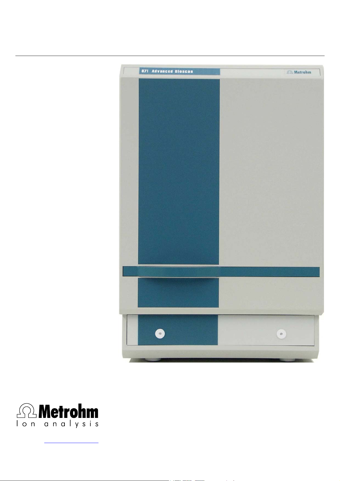
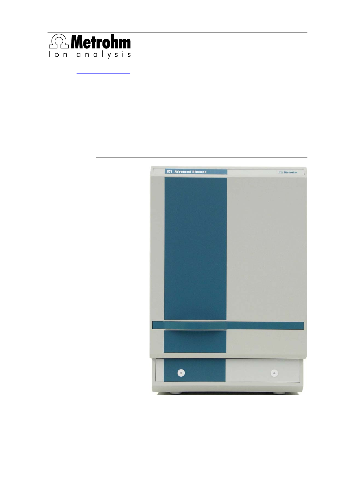
871 Advanced Bioscan
CH-9101 Herisau/Switzerland
E-Mail info@metrohm.com
Internet www.metrohm.com
Instructions for Use
8.871.1003
Page 2

Page 3
CH-9101 Herisau/Switzerland
E-Mail info@metrohm.com
Internet www.metrohm.com
871 Advanced Bioscan
8.871.1003 Instructions for Use
8.871.1003 01.2007 / chs
Page 4

Teachware
Metrohm AG
Oberdorfstrasse 68
CH-9101 Herisau
teachware@metrohm.com
1. Edition 2007
These instructions are protected by copyright. All rights reserved.
Although all the information given in these instructions has been checked with great care, errors
cannot be entirely excluded. Should you notice any mistakes please inform the author at the
address given above.
Page 5

1.1 Instrument description
Table of contents
1 Introduction ................................................................ 1
1.1 Instrument description ................................................................................1
1.2 Parts and controls .......................................................................................2
1.2.1 Front.................................................................................................................... 2
1.2.2 Rear .................................................................................................................... 3
1.2.3 Interior................................................................................................................. 4
1.3 Information on the Instructions for Use .....................................................6
1.3.1 Organization .......................................................................................................6
1.3.2 Notation and pictograms.................................................................................... 7
1.4 Safety notes .................................................................................................8
1.4.1 Electrical safety................................................................................................... 8
1.4.2 General precautionary rules ............................................................................... 8
2 Installation ................................................................. 9
2.1 Setting up the instrument............................................................................9
2.1.1 Packaging...........................................................................................................9
2.1.2 Check.................................................................................................................. 9
2.1.3 Location .............................................................................................................. 9
2.1.4 Arrangement of the instruments......................................................................... 9
2.2 Mains connection ........................................................................................9
2.2.1 Fuses ................................................................................................................ 10
2.2.2 Mains cable and mains connection ................................................................. 10
2.2.3 On/off switching of the instruments ................................................................. 11
2.3 Connection to PC ......................................................................................11
2.3.1 Connecting cable .............................................................................................11
2.3.2 Software installation.......................................................................................... 11
2.3.3 First Login ......................................................................................................... 12
2.3.4 Create a system ............................................................................................... 12
2.4 Capillary connections ...............................................................................12
2.4.1 Connection of the 6.5324.000 Bottle rack (option).......................................... 12
2.4.2 Connect Drainage tube .................................................................................... 13
2.4.3 Connecting the pulsation absorber.................................................................. 13
2.4.4 Connection of the sample path........................................................................ 13
2.4.5 Installation of the precolumn ............................................................................ 14
2.4.6 Installation of the IC column............................................................................. 14
2.4.7 Measuring cell .................................................................................................. 15
3 Basic principles........................................................ 16
3.1 Introduction ...............................................................................................16
3.2 Measuring conditions................................................................................16
3.3 Pulsed amperometric detection ...............................................................17
3.3.1 Optimization of the PAD parameters ............................................................... 18
3.4 Optimization of the measuring potential ..................................................19
4 Notes - Maintenance - Faults................................... 22
4.1 Handling the 871 Advanced Bioscan .......................................................22
4.2 Practical notes on ion chromatography...................................................22
4.2.1 Separating columns ......................................................................................... 22
4.2.2 High-pressure pump ........................................................................................ 23
4.2.3 Eluents .............................................................................................................. 24
871 Advanced Bioscan / Instructions for Use 8.871.1003
I
Page 6

1 Introduction
4.2.4 Connections ..................................................................................................... 24
4.3 Maintenance and servicing .......................................................................25
4.3.1 General information.......................................................................................... 25
4.3.2 Shutdown ......................................................................................................... 25
4.3.3 Cleaning the working electrode ....................................................................... 26
4.3.4 Changing separating columns......................................................................... 26
4.4 Faults and malfunctions............................................................................28
4.4.1 Malfunctions and their rectification .................................................................. 28
4.5 Instrument test with the dummy cell ........................................................30
4.6 Diagnostic tests / Validation / GLP ...........................................................31
5 Appendix ................................................................... 32
5.1 Technical data............................................................................................32
5.1.1 Measuring unit.................................................................................................. 32
5.1.2 Operating modes ............................................................................................. 32
5.1.3 Autozero ........................................................................................................... 33
5.1.4 Injection valve................................................................................................... 33
5.1.5 Oven ................................................................................................................. 33
5.1.6 Mains connection............................................................................................. 33
5.1.7 RS 232 Interface............................................................................................... 33
5.1.8 I/O lines ............................................................................................................ 33
5.1.9 Signal output .................................................................................................... 34
5.1.10 Safety specifications ........................................................................................ 34
5.1.11 Electromagnetic compatibility (EMC) .............................................................. 34
5.1.12 Ambient temperature ....................................................................................... 34
5.1.13 Housing ............................................................................................................ 34
5.2 Standard equipment ..................................................................................36
5.3 Optional accessories.................................................................................39
5.4 Warranty and Conformity ..........................................................................44
5.4.1 Warranty ........................................................................................................... 44
5.4.2 Declaration of Conformity ................................................................................ 45
5.4.3 Quality Management Principles ....................................................................... 46
5.5 Index...........................................................................................................47
II
871 Advanced Bioscan / Instructions for Use 8.871.1003
Page 7

1.1 Instrument description
List of figures
Figure 1: Front 871 Advanced Bioscan ....................................................................2
Figure 2: Rear 871 Advanced Bioscan ..................................................................... 3
Figure 3: Interior 871 Advanced Bioscan.................................................................. 4
Figure 4: Mains connection plug ............................................................................ 10
Figure 5: Potentials applied during pulsed amperometric detection (PAD) ........... 17
Figure 6: Example of a hydrodynamic voltammogram of a substance (A) with the
additional presentation of the measured values for the pure eluent (B) . 19
Figure 7: Example of a scan of a substance (A) with the additional
representation of the scan of the pure eluent (B) .................................... 20
871 Advanced Bioscan / Instructions for Use 8.871.1003
III
Page 8

Page 9

1.1 Instrument description
1 Introduction
1.1 Instrument description
The 2.871.0010 Bioscan is a PC-controlled measuring instrument for
the sensitive analysis of carbohydrates by ion chromatography using
pulsed amperometric detection. The compact housing of the 871 Advanced Bioscan contains several IC system components:
• Column compartment – the perfect insulation of the housing cre-
ates not only stable thermal conditions for the separating columns,
but also shields the system from electromagnetic interference; in
addition to the column it also contains the detection cell, pulsation
absorber and injection valve.
• Oven – amperometric determinations require extremely stable
thermal conditions. The built-in column compartment oven ensures
that all important components can be set exactly to a temperature
from 10°C above room temperature to 45 °C with a stability of
0.1°C.
• All components that come into contact with the eluent and the
sample, except the electrodes, are metal-free.
• Signal converter – the 871 Advanced Bioscan contains its own
analog/ digital converter for the detector signal. This means that
complete control of the instrument is possible from a PC via an
RS232 interface.
• Injection valve – for individual injections or for use with a sample
changer
Together with the 818 IC Pump, the 871 Advanced Bioscan forms a
complete IC system for carbohydrate analysis. Operation is via a PC
connected to the RS232 interface and uses the included «IC Net» control and evaluation program. This software fulfills all the requirements
which are placed today on a modern integration software: 1-point or
multi-point calibration, internal or external standard, selectable algorithms for non-linear calibration, numerous Integration modes with selectable parameters and integration events, various peak recognition
methods, peak editor, free scaling, superimposition of several chromatograms, post-treatment of chromatograms, high-performance GLPconform report generator with output interfaces for monitor, printer and
external databases.
871 Advanced Bioscan / Instructions for Use 8.871.1003
1
Page 10
1 Introduction
1.2 Parts and controls
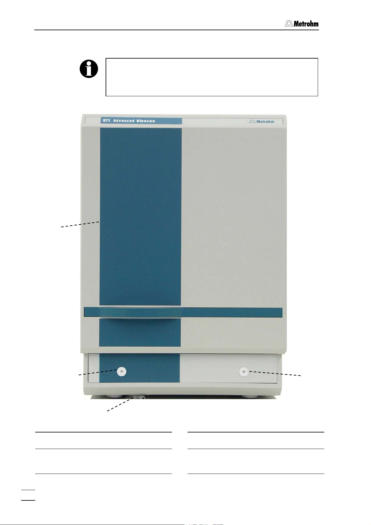
In this Section you will find the numbers and designations of the parts
and controls of the 871 Advanced Bioscan. The numbering applies
throughout the Instructions for Use, i.e. bold numbers in the text (e.g.
4
) refer to the parts and controls illustrated here.
1.2.1 Front
1
2
4
3
Figure 1: Front 871 Advanced Bioscan
Door to interior
1
Feed through for capillary
2
Inlet for eluent and sample
2
871 Advanced Bioscan / Instructions for Use 8.871.1003
Drain opening for leaking liquid
3
Feed through for capillary
4
outlet for eluent and sample
Page 11
1.2 Parts and controls
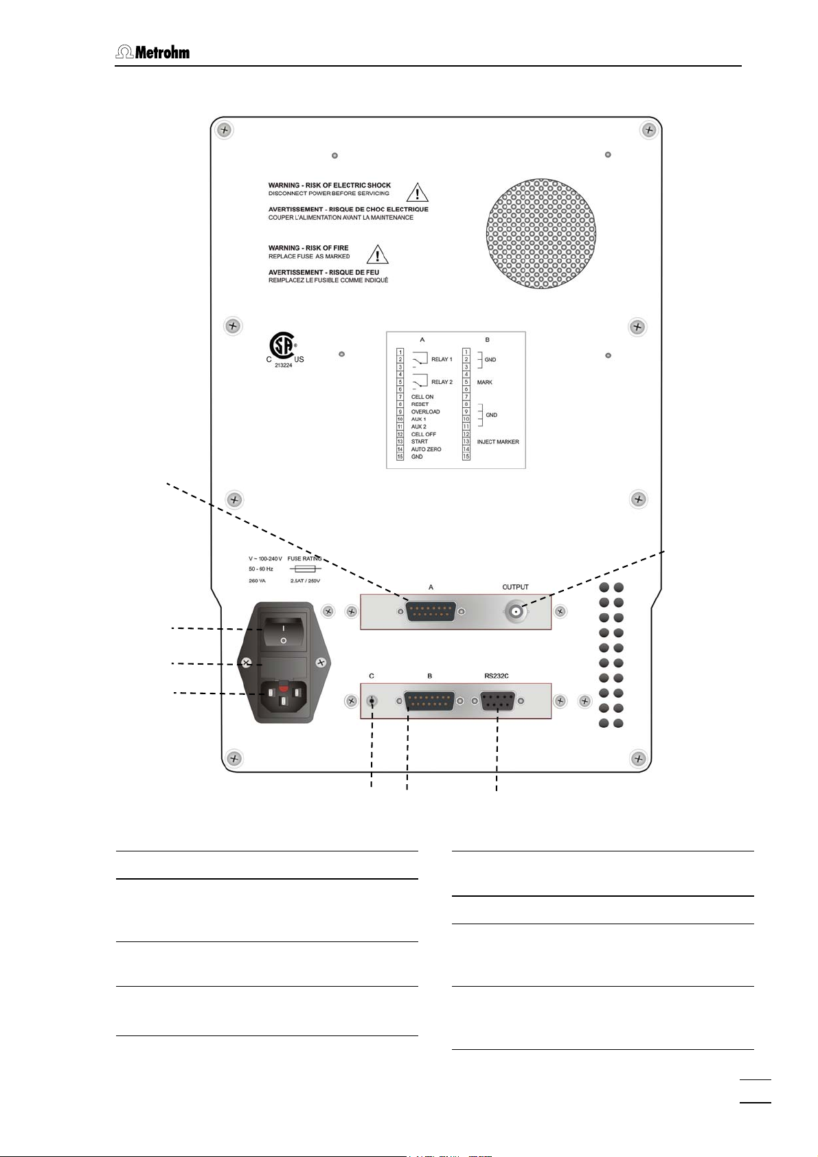
1.2.2 Rear
5
6
7
8
Figure 2: Rear 871 Advanced Bioscan
Remote connection A
5
Mains switch
6
to switch instrument on and off:
I = ON 0 = OFF
Fuse holder
7
changing the fuses, see section 2.2.1
12
9
10
11
Connection C Manual valve
9
(not used with IC Net)
Remote connection B
10
RS232 interface
11
Connection of the PC; see chapter 5.1
for details
Mains connection plug
8
mains connection, see section 2.2
871 Advanced Bioscan / Instructions for Use 8.871.1003
Analog signal
12
AD/DA-converted signal (not used
with IC Net; see chapter 5.1)
3
Page 12
1 Introduction
1.2.3 Interior
13
14
15
16
17
18
19
20
34
33
32
31
30
Metrosep
Carb 1
21
22
23
24
25
26
27
Figure 3: Interior can
871 Advanced Bios
28
29
Column connection capillary
13
Connection to Flow cell
Flow cell
14
see section 2.4.7
PEEK capillary
4
871 Advanced Bioscan / Instructions for Use 8.871.1003
Page 13

1.2 Parts and controls
Electrode cable
15
(black)
connection for reference electrode
IC column
16
e.g. Metrosep Carb 1 (6.1013.000)
for carbohydrate analysis
Column holder
17
Injection valve
18
see section 2.4.4
Sample loop
19
Connection capillary
20
connection injection valve 18 – precolumn 22
PEEK capillary
Connection for electrode cable
21
Precolumn
22
see section 2.4.5
Connection capillary
23
connection precolumn 22 – IC column 16
PEEK capillary
Connection capillary
24
for sample. Connection to injection
valve 18
PEEK capillary
Connection capillary
25
for eluent. connection 818 IC Pump –
Pulsation absorber 26
PEEK capillary
Pulsation absorber
26
6.2620.150
Connection capillary
27
connection Pulsation absorber 26 –
injection valve 18
PEEK capillary
Oven
28
Connection capillary
29
for sample. Connection injection
valve 18 – Waste
PEEK capillary
Oven heating fan
30
Connection capillary
31
Connection Flow cell 14 – Waste
PEEK capillary
Electrode cable (blue)
32
connection for auxiliary electrode
Electrode cable (red)
33
connection for working electrode
Measuring cell holder
34
871 Advanced Bioscan / Instructions for Use 8.871.1003
5
Page 14

1 Introduction
1.3 Information on the Instructions for Use
Please r roug e In ction r Use carefully before you put
the 871 Advanced Bioscan into operation. The Instructions for Use
contain information and warnings to which the user must pay attention
in order to assure safe operation of the instrument.
ead th h thes stru s fo
1.3.1 Organization
These Instructions for Use 8.871.1003 for the 871 Advanced Bioscan
provide a comprehensive overview of installation, startup procedure,
operation, fault rectification and technical specifications of this instrument. The Instructions for Use are organized as follows:
Sect. 1 Introduction
Sect. 2 Installation
Sect. 3 Basic principles
Sect. 4 Notes - Maintenance - Faults
Sect. 5 Appendix
General description of instrument, parts and controls and
safety notes
Installation of instrument and accessories
Information about the pulsed amperometric detection
Notes on ion chromatography, maintenance, fault rectification, diagnostic tests, validation
Technical data, standard equipment, options, warranty,
declarations of conformity, index
To find the required information on the instruments, use either the Ta-
ble of contents or the Index at the back.
6
871 Advanced Bioscan / Instructions for Use 8.871.1003
Page 15
1.3 Information on the Instructions for Use
1.3.2 tograms
Notation and pic
The following notations and pictograms (symbols) are used in these Instructions for Use:
Fill entry
SYSTEM STATE P
<OK>
23 Part or control of 871
Menu item, parameter or
v
alue
in the software
rogram window
the software
in
Button
in the software
azard
H
This symbol draws attention to a
possible danger to life or of injury if
t e associated directio
h ns are not
followed correctly.
arning
W
This symbol draws attention to possible damage to instruments or instrument parts if the associa
ctions are not followed correctly.
re
ted di-
Caution
his symbol marks important infor-
T
mation. First read the associated dir ctions before you continu
e e.
Comment
This symbol marks additional information and tips.
871 Advanced Bioscan / Instructions for Use 8.871.1003
7
Page 16
1 Introduction
1.4 Safety notes
1.4.1 Electrica
• Mains co
• Op ced Bioscan ening the 871 Advan
• Protection against static charges
l safety
W
hile electrical safety in the handling of the 871 Advanced Bioscan is
a
ssured in the context of the specifications EN 61010-1 (protection
c
lass
I, degree of protection IP20), the following
noted:
nnection
Setting of the mains voltage, checking the mains fuse and the
mains connection must be effected in accordance with the instruc-
tions in Section 2.2.
If the 871 A
instrument m pened nor must parts be removed from it,
o h er of coming into contact with components
therwise t ere is a dang
which are l ment from all
vo n it and ensure that the mains cable
ltage sources before you ope
is disconne
dvanced Bioscan is connected to the power supply, the
ust not be o
ive. Therefore always disconnect the instru
cted from mains connection
8
points should be
!
E components are sensitive to static charging and can be
lectronic
destroyed b
inside the 871 Advanced Bioscan, you should ground yourself and
any tools you are using by touching a grounded object (e.g. housing
of the instrument or a radiator) to eliminate any static charges which
exist.
y discharges. Before you touch any of the components
1.4.2 General precautionary rules
• Handling of solvents
Check all lines of the IC system periodically for possible leaks. Follow
the relevant instructions regarding the handling of flammable and/or
toxic solvents and their disposal.
• Never block drain opening for spilled liquids
On the bottom of the interior directly below the front door there is a
3
drain opening
3
. Due to safety consideration, take care that these openings may
never be blocked.
. Spilled liquids can flow directly to the drain opening
8
871 Advanced Bioscan / Instructions for Use 8.871.1003
Page 17
2.1 Setting up the instrument
2 Installation
2.1 Setting up the instrumen
2.1.1 Packaging
The 8 an is ith the separately
71 Advanced Biosc supplied together w
packed accessories in special p ining shock-absorbing
foam linings designed to provide excellent protection. The actual
instruments are packed in an evacuated polyethylene bag to prevent
the ingress o lease store ckaging as only it can
assure transport of the instruments free from damage.
2.1.2 Check
To unpack the 871 Advanced Bioscan, lift it from its box by both
hands. Never lift the 871 Advanc n at its front doors, but at its
sides.
After receipt, immediately check nt is complete and
has arrived without damage (compare with delivery note and list of
accessories in section 5.2). In the case of transport damage, see
instructions in section 5.4 "Warran
2.1.3 Location
f dust. P all this special pa
t
ackaging conta
ed Biosca
whether the shipme
ty".
Position the instruments in the l for
operation, free from vibrations and protected against a corrosive atmosphere and contamination by chemicals. The same applies to all
other components of the IC syste
To avoid disturbing temperature
compartment, the entire system servoir
must be protected against direct sunlight.
2.1.4 Arrangement of the instruments
In general, the IC pumps should be set up at the very bottom and the
IC detectors at the very top.
2.2 Mains connection
Follow the instructions below for connecting to the power supply. If the
instrument is operated with wrong mains fuse, there is a danger of fire!
aboratory at a location convenient
m.
influences on the insulated column
including pump and eluent re
871 Advanced Bioscan / Instructions for Use 8.871.1003
9
Page 18

2 Installation
2.2.1 Fuses
Fuses 2.5AT/250V are installed in fuse holder 7 of the 871 Advanced
Bioscan.
Ensure that the instrument is never put into operation with fuses of a
different type as this could cause a fire!
For checking or changing fuses, proceed as follows:
1 Disconnect mains cable
Disconnect mains cable from mains connection plug 8.
2 Remove fuse holder
Take fuse holder 7 until it dangles (on the bottom of the fuse
holder is a small opening to grip it).
3 Take out fuse
Carefully take the fuse out of the fuse holder.
2.2.2
6
7
8
Figure 4: M
ains connection plug
Mains ca
4 Insert fuse
Change fuses if necessary and reinsert in fuse holder.
5 Install fuse holder
Install fuse holder.
6 Mains switch
to switch instrument on and off:
I = ON 0 = OFF
7 Fuse holder
8 Mains connection plug
ble and mains connection
M
ains cable
Th
e instrument is supplied with one of three mains cables
• 6.2122
• 6.2122.040 with plug CEE(7), VII (Germany, …)
• 6.2133.070 with plug NEMA 5-15 (USA, …)
which are three-cored and fitted with a plug with an earthing pin. If a different plug has to be fitted, the yellow/green lead (IEC standard) must
be connected to protective earth (protection class 1).
10
871 Advanced Bioscan / Instructions for Use 8.871.1003
.020 with plug SEV 12 (Switzerland, …)
Page 19

2.3 Connection to PC
Any break in the earthing inside o
a hazard!
Mains connection
Plug the mains cable into mains c
vanced Bioscan (see Figure 2).
2.2.3 On/off switchin
The 871 Advanced Bioscan is switched on and off using mains switch
6. Do not switch the IC components on before all cable connections
have been established.
2.3 Conne
2.3.1 Connecting
ction to PC
cable
Always switch off 871 Advanced Bioscan and PC before you connect
the two
Connect the RS232 interface 11 at the 871 Advanced Bioscan to a serial COM port at the PC using the 6.2134.180 Cable (9-pin/9-pin).
r outside the instrument can make it
onnection plug 8 of the 871 Ad-
g of the instruments
instruments with the 6.2134.180 Cable.
2.3.2 Software
installation
C program «IC Net» (from Version 2.3 SR4) is required for opera-
The P
ting the 871 Advanced Bioscan; this is included in the standard equipment on CD 6.6034.033. This program runs under the operating systems Windows 2000 and Windows XP and is installed as follows:
1 Install program
• Insert the installation CD 6.6034.033 into your CD-ROM drive.
• If the autorun option for the CD drive is disabled, select
<Start> and Run. Browse for the Setup.exe file on the installa-
tion CD and click on
• Click "
IC Net" and follow
program (see Instruction
more detailed description).
2 Files
The installation program copies the files from the installation CD
into the folder entere
and Autodatabase. The following subfolders are also gener-
Net
ated, among others:
Data Folder for storage of chromatogram files
Devices Folder for storage of device files (*.dev)
ExcelReport Folder for Excel reports (*.xls)
Methods Folder for storage of method files (*.mtw)
<OK>.
the on-screen prompts of the Setup
s for Use «IC Net», Section 1.5 for a
d by you and generates the subfolders
(*.chw) and batch reprocessing files (*.bar)
IC
871 Advanced Bioscan / Instructions for Use 8.871.1003
11
Page 20

2 Installation
Reports Folder for storage of report files (*.txt)
and graphic files (
Systems Folder with subfolders with system files
(
*.smt) and sample queue files (*.que).
*.wmf)
The installed files (incl. system and method files) are generally not
write-protected. To prevent these files from being deleted by mistake,
switch on the write-protection or make a backup co
rectory.
2.3.3 First Login
S are is described in the provided Soft-
tarting and closing of the Softw
ware Instructions for Use «IC Net», Section 2.
py in another di-
The Add User window (see below) o
program after installing the software and a user with Administrator access rights is crea
ted.
pens the first time you launch the
2.3.4 Create a system
Create in «IC Net» a system to control the 871 Advanced Bioscan. Proceed as described in Sectio 4 ftware Instructions for Use
«IC Net»: System wizard. Add the 871 Advanced Bioscan (they are listed
under "Metrohm Detectors" o e the port to
which it is connected.
2.4 s
2.4.1 Connect
Capillary connection
he capillary connections described below are necessary for operating
T
the 871 Advanced Bioscan.
ion of the 6.5324.000 Bottle rack (option)
Th upply vessels can
e optionally available 6.5324.000 Bottle rack for s
be placed on top of the 871 Advanced Bioscan. For the tubing connectio C Pump.
ns to the 818 IC Pump see Instructions for Use 818 I
n .4.1 of the So
) t the system, and choos
12
871 Advanced Bioscan / Instructions for Use 8.871.1003
Page 21

2.4 Capillary connections
2.4.2 Connect Drainage tube
Connect silicone tube 6.1816.050 to the drain opening 3 and lead it to a
waste container.
2.4.3 Connecting the pulsation absorber
The 818 IC Pump needs to be deaerated before putting it into operation. The procedure is described in t
Use.
To protect the column material from any pressure shocks which the injection may cause we recommend the insertion of the 6.2620.150 MF
Pulsation absorber between the high-pressure pump and the injec-
ollows (see Figure 3): tion valve. This is done as f
1 Connect the pulsation absorber
• Place pulsation absorber 26 on the floor in the interior of the
871 Advanced Bioscan.
he 818 IC Pump Instructions for
2 Connection to pump
• Connect the 6.2821.120 PEEK Filter unit described in the
Instructions for Use 818 IC Pump to the 818 IC Pump.
• Lead PEEK capillary 25 from connection piece of the filte
outwards through opening 2 of the Bioscan and attach it to
one of the 26
absorber.
3 Connection to injection valve
• Connect PEEK capillary 27 to the second connection of the
pulsation absorber 26 and to the injection valve 18 (see
Figure 3).
The pu
with eluent before a separating column is connected. To do that, disconnec
containe
The 6.26
tions.
lsation absorber is filled with isopropanol and must be rinsed
t PEEK capillary
r an turn on the 818 IC pump for 10 min.
20.150 Pulsation absorber can be operated in both direc-
connections on the top side of the pulsation
27
from the injection valve, lead it into a w
r unit
aste
2.4.4 Connection o
871 Advanced Bioscan / Instructions for Use 8.871.1003
f the sample path
Conne
ction of the sample path is done as follows (see Figure 3):
1 Conne
• Lead PEEK cap
Bioscan and co
ct aspirating tube
illary 24 through opening 2 of the Advanced
nnect it to the injection valve 18.
13
Page 22

2 Installation
2 Connect outflow tube
• Lead PEEK cap ed
Bioscan and co e
other end to a waste container.
illary 29 through opening 2 of the Advanc
nnect it to the injection valve 18. Lead th
2.4.5 Install ti
a on of the precolumn
T of easily exchangeable precolumns protects the separating
he use
columns and prolongs their lifetime. Recommended precolumn for the
871 Advanced Bioscan:
When you install the column always ensure that this is inserted cor-
rectly in accordance with the flow direction shown.
New I
C precolumns are normally filled with solution and sealed at both
en s.
Before the precolumn is installed in the system you must make d
sure that this solution is freely miscible with the eluent used (check
manufacturer's specifications).
1 Connect precolumn
• Remove end caps from the precolumn 22.
• Screw PEEK capillary 20 to the injection valve 18.
• Screw PEEK capillary 20 to precolumn 22.
• Screw PEEK capillary 23 to the other end of the precolumn
22.
2 Rinse the precolumn
• Place a beaker beneath PEEK capillary 23.
• Switch on the 818 IC Pump for 10 min.
Metrosep Carb 1 Guard.
2.4.6 Installation of the IC column
Recommended separation column for the 871 Advanced Bioscan: Met-
rosep Carb 1 - 250
14
871 Advanced Bioscan / Instructions for Use 8.871.1003
When you install the column always ensure that this is inserted correctly in accordance with the flow direction shown.
New IC columns are normally supplied filled with liquid and sealed at
both ends. Before inclusion
this solution is fully miscible with the eluent to be used (observe the
information provided by the manufacturer).
1 Connect IC column
• Remove end caps from the IC column 16.
• Screw PEEK capillary 23 to the IC column 16.
• Screw PEEK capillary 13 to the other end of the IC column
16.
.
in the system you must make sure that
Page 23

2.4 Capillary connections
2 Rinse the IC column
• Place a beaker beneath PEEK capillary 13.
• Switch o
n the 818 IC Pump for 10 min.
3 Fix IC column
• Fix the IC column 16 in column holder 17.
2.4.7 Measuring cell
Install the measuring cell according to the measuring cell documentation.
871 Advanced Bioscan / Instructions for Use 8.871.1003
15
Page 24

3 Basic principles
3 Basic principles
3.1 Introduction
The 871 Advanced Bioscan
tector in three different working modes:
• DC mode A constant potential is applied to the working elec-
trode. The analyte substance
duced according to their electrochemical properties
The current that is produced is m
Scan mode Current-potential curves are recorded in order to de-
•
termine the optimum parameters for amperometric
detection (DC and Pulse). This is done by passing a
solution that contains only the substance of interest
through the measuring cell and recording a currentpotential curv
• nt potentials are applied cyclically to
Pulse mode Three differe
the working electrode. This frees
face from any adhering reaction products and reactivates it for the next measurement. As
operating mode that is primarily
Advanced Bioscan for carbohydrate analysis it
described in detail in Section 3.2.
can be operated as an amperometric de-
s are oxidized or re-
easured.
e.
the electrode sur-
this is the
used with the 871
.
is
3.2 Measuring
Amperometric detection takes place with a flowing current and therefore with a chemical convers
cal reaction depends directly on various physical parameters, among
other things. In ord
stable baseline or reproducible signals) it is necessary to take the foll
owing points into consideration:
• Temperature The reactions occurring at the
• pH so
conditions
ion of the analyte. The course of a chemi-
er to obtain optimum measuring conditions (e.g.
(oxidation and reduction) are influenced by the temperature. However, this applies not only to the conversion of the analyte, but also for interfering reactions that produce the background current. This is
the reason why a consta
sary precondition for obtaining a stable baseline
and reprodu
carbohydrates, lower temperature
are suitable. Furthermore, the flo
be operated above 45 °C over a longe
Just like the temperature, the pH of the eluent al
has a direct influence on the electrochemical reactions at the working electrode. pH alterations cause
cible signals. For the determination of
working electrode
nt temperature is a neces-
s (30 °C – 35 °C)
w cell should not
r time period.
16
871 Advanced Bioscan / Instructions for Use 8.871.1003
Page 25

3.3 Pulsed amperometric detection
a displacement of the characteristic current/potential curves (v
the reduction of the signal intens
nal/noise ratios. In order to
baseline and reproducible measuring conditions are
ned care should be taken that the pH of the
obtai
eluent is correct.
Pulsation Electrochemical reactions at the electrode surfaces
•
depend on the transport of the reacting substances
to the electrode. This is why a constant eluent flow
is crucial, both for a stable baseline and also for reproducible signals. This is why pulsation-free eluent
supply must be ensured. You should use the pulsation absorber provided (see Section 2.4.3).
oltammograms). Possible results are
ity and lower sig-
ensure that a stable
3.3 Pulsed amperometric detection
During an amperometric determination the reaction products formed on
the working electrode can alter its surface properties by adsorption. In
pulsed amperometric detection (PAD) it is possible to apply further potentials cyclically in addition to the detection potential in order to ensure
a constant electrode surface. In this way the electrode surface is renewed after each current measurement and remains in this activated
condition.
The exact potential steps are shown in Figure 5 as a function of time.
2.01.0
Figure 5: Potentials applied during pulsed amperometric detection (PAD)
The working potential E1 is applied during the time t1 with the signal
being measured in ts. The high positive potential E2 causes the oxidative removement of reaction products from the electrode surface, which
is reduced to a reconditioned surface during t3.
871 Advanced Bioscan / Instructions for Use 8.871.1003
17
Page 26

3 Basic principles
3.3.1 Optimization of the PAD parameters
When adapting the method parameters the preset paramete
initially be used. Descriptions of various applications are availa
Metrohm AG in the form of Application Works and Application Notes.
These can be obtained from your local Metrohm agency or on the Internet under www.m
The potential profile shown in Figure 5 must always be matched to the
analyte under investigation. 7 parameters must be taken into account:
potentials E1, E2 and E3, time intervals t
time ts. Some ic conditions are preset; this makes configuration
easier. These are described below.
Measuring int
The measuring pot stigated.
If no data is available in the literature that can initially be used for optimization then you
reason the 871 Adv
cord the correspon
As each change in
cur at the working
started when the signal has stabilized itself to a large extent. This time
is defined as t1 –
ground current and should therefore be selected so that it is not too
small. In practice a
etrohm.com
bas
erval (E1, t1 and ts)
ential depends on the substance being inve
can determine these parameters yourself. For this
anced Bioscan provides the scan mode. How to re-
ding voltammograms is described in Section 3.4.
potential can cause a higher charging current to oc-
electrode, the current measurement itself is only
ts (see Figure 5). It influences the level of the back-
time of 0.1 to 0.4 s is frequently used.
.
1, t2 and t3 and the measuring
rs should
ble from
The measuring inte
The available value
rval ts is selectable with the 871 Advanced Bioscan.
s depend on t1.
Regeneration interval (E2, E3, t2 and t3)
The potentials E2 and E3 which ar
electrode surface are primarily determined by the material of the working electrode.
With the gold electrode the oxide layer is formed at E2 > +200 mV
(Ag/AgCl) under alkaline conditions. Higher potentials accelerate oxide
formation, therefore in practice E2 = +750 mV and t2 = 0.2 s are often
selected.
For example, –800 mV at 0.2 s or –150 mV at 0.4 s can be selected for
E3 and t3.
Measuring fre
In pulsed amperom
vals (t1 + t2 + t3)
reciprocal of this c
frequency.
quency
etric detection the total of the three individual inter-
represents the duration of one measuring cycle. The
ycle duration (in seconds) gives the possible pulse
e required for the regeneration of the
18
871 Advanced Bioscan / Instructions for Use 8.871.1003
Page 27

3.4 Optimization of the measuring potential
3.4 Optimization of t
An optimization of
may bring benefits
a) The sensitivity
against the bac
b) The selecti of the detection is negatively affected by the analyte
peak overlappi
optimally separ
If there are no suita
mogram is require
the given potential
dividual chemical s ces.
here are two different types of voltammograms, each of which is suit-
T
able for solving a different problem: a hydrod
and a scan voltammogram.
A hydrodynamic voltammogram is made of several chromatograms
recorded in the DC mode. This involves recording a chromatogram of
the substance under investigation, dissolved in eluent, at a constant potential. The potential is now varied several times and the process is repeated. Finally the height of the current peak obtained is evaluated and
plotted against the particular potential. Figure 6 shows a schematic example of su
vity
ch a hydrodynamic voltammogram:
he measuring potential
the measuring potential for amperometric detection
in the following situations:
of the detection of the analyte is to be increased
kground signal.
ng with a second substance peak that has not been
ated by chromatography.
ble literature data available, recording of a voltam-
d. This is a curve showing the relationship between
and the measured current. It is characteristic for in-
ubstances or even whole classes of substan
ynamic voltammogram
I
Figure 6: Example of a hydrodynamic voltammogram of a substance (A)
with the additional presentation of the measured values for the
pure eluent (B)
This method is recommended if the analyte is not present in a pure
form. It also provides more realistic information about the signal/noise
ratio and the selectivity towards overlapping peaks.
The scan voltammogram is recorded in the scan mode. The measur-
ing potential is varied backwards and forwards between two given limits
while the analyte is passed through the measuring cell. The actual current is then measured for each potential.
The substance under investigation can be dissolved in the IC eluent
used (e.g. 10 ppm Sucrose in 0.1 M NaOH) and a larger amount (e.g.
100 mL) pumped through the flow cell withou
connected. If you work on trace concentrations of your analyte and
871 Advanced Bioscan / Instructions for Use 8.871.1003
t a separation column
19
Page 28

3 Basic principles
worry about contamination of your IC system you can still inject the
substance into the eluent using a large sample loop (> 500 µL). The
eluent should then be pumped at a very low flow rate (e.g. 0.2 mL/min).
Generally, same conditions should be used as they are needed for the
chromatographic separation (e.g. temperature, pH, eluent etc.).
Figure 7:
Figure 7 shows a schematic exa
mple of a scan:
Example of a scan of a substance (A) with the additional representation of the scan of the pure eluent (B)
When using metal electrodes as the working electrode, such as the
gold electrode used here, the reaction products formed by the amperometric detection during the scan method can form
an interfering
layer on the electrode surface and influence the results. For this reason
a hydrodynamic voltammogram is to
be preferred in such cases.
The following table summarizes the requirements for a
tages and disadvantages of these two methods.
nd the advan-
20
871 Advanced Bioscan / Instructions for Use 8.871.1003
Page 29

3.4 Optimization of the measuring potential
Situation
Requirement
Advantages
Disadvantages
Hydrodynamic Scan
voltammogram voltammogram
• Selectivity for an inadequate • Sensitivity of a substance
IC-separation is to be im-
peak is to be increased
proved
•
Substance can be investi-
gated in the mixture
• Substance must be present
pure form
in a
• IC parameters must be
known
• "Chromatographic" condi-
tions, i.e. a direct check of
• Less time needed for single
substances
selectivity and sensitivity is
possible
• Several substances can be
investigated at the same
time
• More time required for a
single substance
• Possible formation of an ox-
ide layer on the working
electro
de
The final aim is to select a suitable potential for use as the measuring
potential for pulsed amperometric detection. This means that usually a
compromise has to be found between the highest possible sensitivity,
selectivity and reproducibility:
Higher potentials can increase the sensitivity; however, more substances can also be determined and this reduces the selectivity. In order to achieve high reproducibility, a potential from a flatter segment
near the maximum of the analyte voltammogram should be selected. In
the example shown in Figure 6, E
would be such a potential deter-
1
mined in this way.
During the determ ination of the optimum measuring potential the constancy of the parameters pH and temperature as well as the pulsationfree eluent supply are important (see Section 4.2).
871 Advanced Bioscan / Instructions for Use 8.871.1003
21
Page 30

4 Notes - Maintenance - Faults
4 Not
es - Mainte-
nance - Faults
4.1 Handling the 871 Advanced Bioscan
General
Amperometric detection takes place with a flowing current and therefore with a chemical conversion of the analyte. The course of a chemical reaction depends directly on various physical parameters, among
other things. In order to obtain optimum measuring conditions (e.g.
stable baseline or reproducible signals) it is necessary to take the f
lowing points into consideration.
Constant temperature
The 871 Advanced Bioscan allows the interior of the instrument to be
kept at a constant temperature of up to max. 45°C. The lower limit is the
ambient temperature plus 10 °C. You can activate the oven and define
the temperature in the 871 method parameters window (in IC Net).
ol-
onstant pH
C
The characteristic current/potential curves of all electrochemically reactive substances depend very strongly on the pH of the pH eluent used.
This means that you should prepare the eluent ve
its pH at regular intervals.
Pulsation-free eluent flow
Changes to the eluent flow should be avoided as far as is possible. The
6.2620.150 Pulsation Absorber is available for this purpose; it is
mounted between the 818 IC Pump and the injection valve.
Never make dry measurements
The flow-through measuring cell must not be switched on if it is not
being rinsed constantly by the eluent or if the measuring cell is not
connected up properly!
ry carefully and check
4.2 Practical notes on ion chromatography
4.2.1 Separating columns
Separation efficiency
The attainable quality of analyses with an IC system depends to a large
extent on the separation efficiency of the column used. When purchasing an IC column you should ensure that the separation efficiency suf-
22
871 Advanced Bioscan / Instructions for Use 8.871.1003
Page 31

4.2 Practical notes on ion chromatography
fices for the analysis problems at hand. Compare the standard chromatogram enclosed with the column with your own measurements. If
any difficulties arise, you should always first check the quality of the
column by recording a standard chromatogram.
Yo rm i ns
u will find additional detailed info
availa aflets su ation
ble from Metrohm in the le
Work otes, which are available on request free of charge at
s and -N
your local Metrohm agency.
at on on the separating colum
pplied and in the Applic
Prote
To t foreign particles which could have an
adverse influence on the separation efficiency, we advise you to subject
both the eluents and all samples to microfiltration (0.45 µm filter) and
to siphon the eluent through the 6.282
To av ive particles arising from piston seals
of the sure pump, an inline filter should be installed (directly
after the pump). The 6.2821.120 Filter unit PEEK is best suited for
this purpose. It is a part of the standard equipment of the 818 IC Pump.
Storage
Wh he sep d
in turer’s
Regeneration
If the separation properties of the column have deteriorated, it can be
regenerated in accordance with the column manufacturer’s specifications. With the separating columns available from Metrohm, the instructions for regeneration can be found on the leaflet enclosed with every
column.
ction
protect the column agains
oid contamination by abras
high-pres
en not in use, always store t
accordance with the manufac
1.090 Aspirating filter.
arating columns sealed and fille
specifications.
4.2.2 High-pre
In the case of separating columns with carrier material based on silica,
…
only solutions with pH 2
wise the columns could be damaged.
7 may be used for regeneration, other-
ssure pump
P
ulsation dampener
F
or determinations using the Advanced Bioscan pulsation-free high-
p needed. Metrohm
ressure pumps with very constant flow rates are
recommends the use of the 6.2620.150 Pulsation dampener MF. It is
lso used to protect the column material against pressure shocks
a
caused by the injection. Its installation is described in section 2.4.3.
Maintenance
To protect the pump against foreign particles, we advise you to subject
the eluent to microfiltration (0.45 µm filter) and siphon the eluent
through the 6.2821.090 Aspirating Filter.
In many cases, an unstable baseline (pulsation, flow fluctuations) can
be traced to contaminated valves or faulty, leaky piston seals.
871 Advanced Bioscan / Instructions for Use 8.871.1003
23
Page 32

4 Notes - Maintenance - Faults
Contaminated valves are cleaned by rinsing with water or organic solvents. When the cleaned valves are reinstalled, you must ensure that
the flow direction is correct.
The replacement of piston seals has to be done
the pump manufacturer’s directions. The correspo
work for the 818 IC Pump is described in the 818 Instruction
in accordance with
nding maintenance
s for Use.
Salt crystals between the piston and the seal are
particles, which can enter the eluent. These lead to con
valves, pressure rise and in extreme cases to sc
thus essential to ensure that no precipitates can appear (see also
section 4.2.3).
4.2.3 Eluents
Treatment
For the preparation of the eluents only chemicals of a purity degree of
at least "p.a." should be used. For diluting please use only high purity
water.
Fresh eluents should always be micr
gassed (with N
eluents and eluents with
use a CO
6.5324.000 Bottle rack).
The supply vessel containing the eluent must be closed as tightly as
possible to avoid excessive evaporation.
the cause of abrasive
taminated
ratched pistons. It is
ofiltered (0.45 µm filter) and de-
, He or by using an 837 Eluent Degaser). For alkaline
2
low buffering capacity one should preferably
absorber (e.g. the absorber supplied with the optional
2
Influence of various parameters
• Concentration: An increase in the concentration usually leads
• pH: pH alterations lead to shifts in the dissociation
Eluent change
hen the eluent is changed, it must be ensured that no precipitates
W
an be formed. Solutions used in direct succession must therefore be
c
miscible. If the system has to be rinsed with an organic solution, several
solvents with increasing or decreasing lipophilic character may possibly
have to be used (e.g. water ↔ acetone ↔ chloroform).
4.2.4 Connections
All connections between injector, column and detector must be as short
as possible, have a low volum
to shorter retention times and quicker separati
on.
equilibrium and thus to changes in the retention times.
e and be absolutely tight.
24
871 Advanced Bioscan / Instructions for Use 8.871.1003
Page 33

4.3 Maintenance and servicing
4.3 Maintenance and servicing
information 4.3.1 General
Care
The 871 Advanced Bioscan requires proper care and attention. Excessive contamination of the ins
tions and a shorter service life of the mechanical and electronic parts.
truments could possibly lead to malfunc-
Spilled chemic
especially important to protect the plug connections at the rear of the
instrument (particular the mains plug) against contamination.
Although constructional measures have been designed to virtually
eliminate such a situation, should corrosive media penetrate the interior of the instruments the mains plug must be immediately disconnected to prevent extensive damage to the instrument electronics.
Inform Metrohm service if your instrument(s) have been damaged in
such a way.
The instrument must not be opened by untrained personnel. Please
comply with the safety notes in section 1.4.1.
battery is mounted. If this unit or battery needs service, dispose it according to chemical waste only.
Maintenance by Metrohm service
M
aintenance of the IC system is best done as part of an annual service
p -
erformed by specialists from the Metrohm company. If work is fre
q osive chemicals, it may be nec-
uently performed with caustic and corr
essary to shorten the interval between servicing.
als and solvents should be wiped up immediately. It is
ompartment of the 871 Advanced Bioscan a lithium In the electronic c
The Metrohm service
on the maintenance and servicing of all Metrohm instruments.
4.3.2 Shutdow
871 Advanced Bioscan / Instructions for Use 8.871.1003
n
If the IC System is shut down for a considerable length of time, the entire IC system (without column) must be rinsed with methanol/water
(1:4) to avoid crystallization of eluent with the corresponding subsequent damage.
flow cell must be turned off Rinse with methanol/water (1:4) until the
conductivity of the eluent drops below 10 µS/cm.
department is always willing to offer expert advice
arating column module is removed and bridged. The For rinsing the sep
25
Page 34

4 Notes - Maintenance - Faults
4.3.3 Cleaning the working electrode
The surface of the gold working electrode should be cleaned whenever
you notice that its electrochemical properties have changed. This may
be caused by the deposition of reaction products. High current flows
can also alter the electrode surface; this is indicated by a very reduced
sensitivity after longer periods of use.
In principle, you should avoid too high analyte concentrations or dirty
samples. This measure as well as the regenerative effect of the pulse
technique normally supersedes the polishing of the electrode.
You should on
supplied, if the sensitivity cannot be restored by intensive rinsing of the
flow
cell with water and cleaning the electrode surface by rubbing it
with an eraser.
Use the diamond paste (6.2802.110) supplied to polish the surface of
the electrode together with the polishing disk (6.2802.100). Proceed as
follows:
1 Rinse the polishing disk
Rinse the polishing disk with high purity water before use.
2 Shake the diamond paste
Shake the bottle containing the diamond paste thoroughly before use.
3 Polish the electrode
Add a few drops of the paste to the wet polishing disk and polish the electrode for approx. one m
ments in the of a figure 8. Exert only a slight pressure.
4 Clean the elect
Clean the electrode with a paper tissue moistened with ethanol.
C condition visually and repeat the polishing
heck the surface
process if necessa
ly polish the electrode surface with the polishing paste
inute with uniform move-
form
rode
ry.
5 Rinse electrode and measuring cell
Rinse the electrode and the measuring cell with high purity water.
6 Mount the measuring cell
Remount the measuring cell.
7 Clean the polishing disk
Clean the polishing disk with high purity water and store it dustfree in a plastic cover.
4.3.4 Changin
26
871 Advanced Bioscan / Instructions for Use 8.871.1003
g separating columns
Identical separation system
If you wish to replace an IC separating column by a column of the same
type, proceed as follows (see Figure 3):
Page 35

4.3 Maintenance and servicing
Also change the precolumn when you change the separation column.
1 Remove old column
• Switch off flow cell.
• Switch off pump drive of the 818 IC Pump.
• Unscrew connection capillary 21 to flow cell from the column.
2 Connect new column to injector
• Remove end caps from column.
• Screw preheating capillary 31 to inlet end of separating col-
umn (note flow direction).
3 Rinse column
• Place beaker beneath the column outlet.
• Switch on 818 IC Pump and rinse column with eluent for ca.
10 min with 0.3 mL/min and for ca. 10 min. with 1.0 mL/min,
then switch off pump.
4 Connect column to measuring cell
• Screw connection capillary 21 to measuring cell to outlet end
of separating column.
871 Advanced Bioscan / Instructions for Use 8.871.1003
27
Page 36

4 Notes - Maintenance - Faults
4.4 Faults and malfunctions
4.4.1 Malfunc
tions and their rectification
If difficulties arise with the IC system during analyses, their causes are
best investigated in the order separating column
→ 871 Advanced Bioscan. Several of the malfunctions which may
appear are listed in the following table with details of possible causes
and countermeasures.
Malfunction Cause Rectification
Baseline with high
noise level, pulsation
• Contaminated pump
values
• Faulty piston seals
• Quality of the pump
does not suffice for the
selected sensitivity
• Air bubble in flow cell
• Temperature fluctuation
• Working electrode co
taminated
• Flow cell leakage
• Eluent conta
minated
n-
→ pump → eluent
• Clean the valves (see sec-
tion 4.2.2)
• Replace the piston seals
(see section 4.2.2)
• Use pulsation dampener,
use more powerful pump
or lower the sensitivity
• Remove air bubble, degas
eluent continuously
• Switch on 871 Advan
Bioscan oven
• Clean working electrode
(see Chapter 4.3.3)
• Check capillary connec-
tions at flow cell
• Replace eluent
ced
Drift o
f the
baseli
ne
Decre
asing sensi- • Working electrode con-
tivity
(S/N lower)
High background • Eluent contaminated
signal
• Thermal equilibrium not
yet reached
• Leak in system
• Old Eluent (
CO2)
taminat
taminated sample
• Wrong measuring poten- • Opti
tial tential
• Eluent contaminated
(high background
signal)
• Eluent pH changed
• Wrong measuring
tial / pulse settings
• Very bro
retarded
• Separation column is
bleeding
too much
ed, e.g. by con-
poten-
ad peaks due to
compounds
• Condition system with
heating switched on
• Check connections an
make leakproof
• Replace eluent
• Clean working electrode
(see Chapter 4.3.3), dilute
sample
• Replace eluent
• Check and adjust pH
• Replace eluent
• Optimize parameter
• Await complete elution of
these compounds
• Replace column
d
mize measuring po-
28
871 Advanced Bioscan / Instructions for Use 8.871.1003
Page 37

4.4 Faults and malfunctions
Signal "overload" • Wrong IC-Net parameter • Check settings
'Range'
• Damaged working elec-
trode
• Flow cell is not con-
nected properly
• Wrong m
tial
easuring poten-
• Replace working electrode
• Check cable connections
(REF: black, WE: red,
AUX: blue)
• Optimize measuring po-
tential
Considerable
press
ure drop make leakproof
Con
siderable
pre
ssure rise
Chromatograms
with poor resolution, change in the
retention times
• Leak in system • Check connections and
• Contamination of the
filter in the 6.2821.100
Filter unit PEEK
• Change of column pack-
ing by injection of contaminated samples
• Mounting screws of flow
cell overtightened; 25
µm spacer h
used
• Deterioration in separa-
tion efficiency of the IC
column
• Old Eluent
• Ionic strength or pH of
the sample differs
strongly from eluent
as been
•
Replace the 6.2821.110
Filter
• Regenerate the column
(see section 4.2.1) or replace column
• Check screws of flow cell;
use 50 µm spacer
• Regenerate the column
(see section 4.2.1) or replace column
• Replace eluent
• Dilute sample or change
pH of sample
Note
:
s should always
Sample
microfiltered.
be
Extreme peak
broadening,
splitting (double
peaks)
No signal from
detector
871 Advanced Bioscan / Instructions for Use 8.871.1003
• Dead volume at the col-
umn ends
• Dead volume in IC sys-
tem
• No mains current
• 871 Advanced Bioscan
not switched on
• Faulty fuse
• Measuring cell not con-
nected
• Connection to IC Net is
not working properly
• Replace column
• Check connections
• Check mains supply and
voltage (see Section 2.2)
• Switch on the 871 at the
rear panel
• Replace fuse (see section
2.2.1)
• Check connection
• Check connection
29
Page 38

4 Notes - Maintenance - Faults
4.5 Instrument test with the dummy cell
If any interference occurs whose source
cording or transfer you can selectively c
is suspected to lie in signal reheck the instrument electronics
and the connection to the PC. This is done by connecting the
6.2813.030 Dummy Cell supplied. The temperature in the 871 Advanced Bioscan should be kept constant (30 °C) and, for optimal
shielding, the front door should be closed.
This dummy cell contai
ns a resistor (300 MΩ) and a condenser (0.47
µF) connected in parallel. If a voltage of 0.8 V is applied in the DC mode
t t of 2.6 1%) is measured e condenser
hen a curren 7 nA (± at this cell. Th
f e ates l-
unctions as a nois
f ring
unctioning measu
generator and simul
cell.
the capacitance of a wel
Please make the following settings in IC Net:
If you use these sett seline
(Measure baseline)) you should see a smooth signal line at 2.67 nA. Even
t maximum magn cation the noise shou ot exceed 0.05 n
a ifi ld n A.
30
871 Advanced Bioscan / Instructions for Use 8.871.1003
ings to record a ba (
Control / Startup hard
ware
Page 39

4.6 Diagnostic tests / Validation / GLP
4.6 Diagnostic tests / Validation / GL
The requirements of G ood Laboratory P ctice) include a periodic check of analy rumen producibility and acc Standard ures,
SOP.
Under the title «Application Bulletin No. Validation of
etrohm ion matographs» a
M chro n example of such a standard op-
erating procedure is available from Metrohm; it can be adapted and
used with the 871 Advanced Bioscan.
Further information on the subjects of QA, GLP and validation can also
be found in the broc management with Metrohm»,
which is available fro g
Testing of the electron al funct f Metrohm
instruments can and s ould be performed as par regular service
by trained personnel of the manufacturing company. All Metrohm instruments are equipped with start-up-test routines or perfect functioning of the relevant assemblies when the instrument is
switched on. If no error message is displayed, it may be assumed the
instrument is operating
The Metrohm compan also supplies its instruments with an integrated
diagnostic program which, in the case of possible malfunctions or faulty
behavior, allows the service technician to check the functioning of cert nd
ain assemblies a localize the fault.
LP (G ra
tical measuring inst
uracy using
hure «Quality
m your local Metrohm a
ic and mechanic
h
without faults.
y
P
ts with regard to their re
Operating Proced
277 –
ency.
ion groups o
which check f
t of a
871 Advanced Bioscan / Instructions for Use 8.871.1003
31
Page 40

5 Appendix
5 Appendix
5.1 Technical data
Reference conditions::
Environment temperature +22 °C (
Oven temperature +35 °C
Relative humidity 50 - 65 %
Instrument condition >45 min in service
Adjustment interval
5.1.1 Measuring unit
Operating modes DC, Pulse and Scan
Potential Range: -2.00 ...+ 2.00 V
5.1.2 Operating modes
DC mode Range: 10 pA – 200 µA
Pulse mode Range: 10 nA – 200 µA
Scan Range: 10 nA – 200 µA
±
3 °C)
yearly
Resolution: 10 mV
Resolution: 1, 2, 5 Steps
Filter (avg) off, 0.2, 0.5, 1, 2, 5 s
Resolution filter 1, 2, 5 Steps
Noise < 2 pA (with a dummy cell
300MOhm//0.5uF, filter OFF,
range 1 nA/V, Ec +800mV and
temperature of 35°C)
Resolution: 1, 2, 5 Steps
Filter off, 0.2, 0.5, 1, 2, 5 s
Resolution filter 1, 2, 5 Steps
Puls intervals t1: 0.1 ... 2.0 s
t2: 0 (off) ... 2.0 s
t3: 0 (off) ... 2.0 s
Resolution 10 ms
Meas. intervals 20 ms .. (t1-60ms)
Resolution: 1, 2, 5 Steps
Scan rate.: 1 ... 50 mV/s
Resolution: 1, 2, 5 Steps
Cycle: half, full, continuous
32
871 Advanced Bioscan / Instructions for Use 8.871.1003
Page 41

5.1 Technical data
5.1.3 Autozero
Function Compensation of actual cell current.
Maximum
Initiation
5.1.4 Injection
Positions
Material
Port con
Max. pre
5.1.5 Oven
Tempera
Accurac
Stability
compensation Range: Compensation:
10 pA - 1 nA: 25 nA
2 nA - 5 nA: 250 nA
10 nA - 50 nA: 2.5 µA
100 nA - 2 µA: 25 µA
5 µA - 200 µA: 2.5 mA
Externally (RS232), I/O
valve
Fill .... Inject
Peek
nections 10-32 male threaded fittings
ssure 41 MPa
ture range
y
8 °C above ambient to 45 °C
0.5 °C
0.1 °C
5.1.6 Mains connection
Voltage 100 - 240 VAC auto-sensing
Frequency 50...60 Hz
Power consumption 260 VA, max.
Fuse 5 mm Ø, 20 mm length
5.1.7 RS 232 Interface
Connector Dsub 9 pin (female)
Default settings 38400 Baud, 8 Bit, 1 Stoppbit, no parity
Data acquisition rate 1, 2, 5 or 10 Hz
5.1.8 I/O lines
Connector
Type lines
100…240VAC: 2.5 AT/250V (slow-blow)
2 x Dsub-15 pin, male (A and B) and 1 x phone
jack 2.5 mm, mono (RS 232)
TTL, default status 'high' (5V)
Relais, max. 28V(DC), 500 mA
871 Advanced Bioscan / Instructions for Use 8.871.1003
33
Page 42

5 Appendix
Output lines
5.1.9 Signal ou
Analo ou e 10 V
tput
g tput signal Rang -10 V ... +
5.1.10 Safety specifications
Construction / testing 61010A-1, CSA-
Con
nection A, sensor board
Re
lais: 'RELAY 1' and 'RELAY 2'
TT
L Input: 'CELL ON', 'RESET', 'CELL OFF',
'START' and 'AUTOZERO'
TTL Output: 'OVERLOAD', 'AUX1', und 'AUX2'
V ... +1 V
Resolution it DA converter
Offset
Resolution 5 % steps
According to EN 61010-1 , UL
C22.2 No. 61010-1, protection degree IP20, protection class 1
or -1
20-B
-50 % ... +50 % from max. output voltage
Safety directions
5.1.11 Electromagnetic compat
Emission rds met:
Immunity Standard
5.1.12 Ambient temperature
Nominal operating range +10…+40°C
Storage, transport
The Instructions for Use include information and
warnings h the user must p
order to assu afe operation
to whic ay attention in
re s of the instrument.
ibility (EMC)
Standa
EN 61326,, EN5
EN61000-3-3
s met:
EN 61326, EN61000-4-2, EN6
50204, EN6 0-4-4, EN6100
61000-4-8
6, EN , EN61000-4-11
(at 20…80 % atmospheric hum
–20…+50°C
(at 0…90 spheric humidity
condensing)
% atmo , non-
5011 (class B), EN61000-3-2,
1000-4-3, ENV
100 0-4-5, EN61000-4-
idity)
5.1.13 Housing
Material of cover thane rigi protection
Material of base Steel, enamelled
34
871 Advanced Bioscan / Instructions for Use 8.871.1003
Polyure d foam (PUR) with fire
for fire class UL94VO, CFC-free
Page 43

5.1 Technical data
Width 260 mm
Height 381 mm
Depth 355 mm
Weight
11 kg (without accessories)
871 Advanced Bioscan / Instructions for Use 8.871.1003
35
Page 44

5 Appendix
5.2 Standard equipment
Subject to changes !
All dimensions are given in mm.
d Bioscan 2.871.0010 Advance
Quantity Order no. Description
1 1.871.0010 871 Advanced Bioscan
1 6.1816.060 Drain tubing to UV/VIS Com
and Biosc
Drainage tubing for draining off escaped liquid
Material
uter diam
O eter in mm 6
Inner diam
1 6.1825.210 PEEK sam
For injectio
sure screws
Material PEEK (metal-
Outer diameter in
inches
Volume in m
an
Silicone
eter in mm 4
ple loop 20 µL
n valve, with 2 PEEK pres-
free)
1/16
L 0.02
1 6.1831.010 PEEK capillary 0.25 mm i.d. / 3 m
For all IC co
Material
Outer diame
inches
Inner diameter in mm 0.25
mponents.
PEEK
ter in 1/16
pact IC
1 6.2134.180 Cable RS female 5 m
for Advan
Connecting Bioscan PC
232 DB9 male /
ced Bioscan
cable Advanced
36
871 Advanced Bioscan / Instructions for Use 8.871.1003
Page 45

5.2 Standard equipment
Quantity n
1 6.2156.000 Cable to B ll
Order no. Descriptio
ioscan flow ce
Cable Bios ring cell
can - measu
1 6.2156.010 Recorder cable for Bioscan
Analog cable Bioscan - recorder, for
converted signal (not required in IC system).
1 6.2620.150 Pulsation absorber (metal-free)
For all ion chromatographs
Material PEEK (metal-
free)
in contact with the eluent
Height (mm) 41.5
Outer diameter in mm 76
2 6.2744.010 Pressure screw 5x
With UNF 10/32 connection. For IC instruments, inline dialysis (connection of
PEEK capillaries)
Material PEEK
1 6.2744.014 Pressure screw 2x
With UNF 10/32 connection. For IC instruments, inline dialysis (connection of
PEEK capillaries)
Material PEEK
1 6.2744.040 2 x UNF 10/32 coupling
For connecting 1/16 in. capillaries. For
IC instruments
Material PEEK
871 Advanced Bioscan / Instructions for Use 8.871.1003
37
Page 46

5 Appendix
Quantity Order no. Description
1 6.2802.100 Polishing plate for Bioscan flow cell
Polishing plate for Bioscan working
electrode
1 6.2802.110 Diamond paste for Bioscan flow cell
olishing paste for Bioscan electrode
P
1 6.2813.030 Test cell for Bioscan
Test cell for checking electroni
tions of Bioscan.
1 6.6034.033 IC Net 2.3 CD
Software for data handling (storing,
printing, d s) and m
ods, complete rem
Dialog language: E
with «21
isplaying curve eth-
CFR part 11» regulations
c func-
ote ins nt use.
trume
nglish omplies
CD. C
38
871 Advanced Bioscan / Instructions for Use 8.871.1003
Page 47

5.3 Optional accessories
5.3 Optional accessories
Order no. Description
6.1254.010 Gold flow cell for Bioscan
Flow-through cell for Bioscan, electrode material:
gold
Material Gold
Working electrode
6.1254.020 Distance piece for Bioscan flow cell, 50 µm
50 µm Spacer for Bioscan flow-through cell
Material Plastic
Height (mm) 0.05
6.1254.050 Glassy carb cell for Biosc
Flow cell for Bioscan, electrode materia sy
carbon
on flow an
l: glas
Material Glassy o
Working electrode
6.1254.060 Platinum flo
Flow cell for Bioscan, electrode materia um
Material Platinum
Working electrode
carb n
w cell for Bioscan
l: Platin
871 Advanced Bioscan / Instructions for Use 8.871.1003
39
Page 48

5 Appendix
Order no. Description
54 Silver flow cell for Bioscan
6.12 .070
Flow cell for B
Material Silver
Working electrode
6.1254.110 Au Variocel
Gold measuring cell with replaceable electrode
disks.
6.1254.120 Glassy Carbon Variocell to Advanced Bioscan
Glassy carbon measuring cell with replaceable electrode disks.
ioscan, electrode material: Silver
l to Advanced Bioscan
6.1254.130 Platinum Variocell to Advanced Bioscan
Platinum measuring cell with replaceable electrode
disks.
6.1254.210 Au-Workingelectrode to Variocell
Replacement electrode to Variocell
6.1254.220 Glassy Carbon Workingelectrode to Variocell
Replacement electrode to Variocell
54 Pt-Workin electrode to Va
6.12 .230 g riocell
Replacement electrode to Variocell
6.1254.240 Ag-Working
Replacement
electrode to Variocell
electrode to Variocell
6.1254.310 Reference electrode for Advanced Bioscan
6.1254.410 Spacer 50 µm to Variocell
40
871 Advanced Bioscan / Instructions for Use 8.871.1003
Page 49

5.3 Optional accessories
Order no. Description
6.1803.030 PTFE capillary 0.5 mm i.d. / 3 m
Capillary for inline dialysis, for Dialysis Unit, IC Dialysis Sample
sis Unit
Material PTFE
Outer diameter in
inche
s
Inner diam 0.5
6.2156.030 Remote cable for Adva ed Bioscan
Remote cable Advanced Bioscan - IC Sample Processor
Processor, IC Liquid Handling Dialy-
1/16
eter in mm
nc
6.2156.040 Cable to Variocell
Electrode Cable Advanced Bioscan - Variocell
6.2156.050 e IC Detector - Bioscan - IC Inter-
Analog cabl
face
6.2621.150 Hexagon key 3 mm for Bioscan
Hexagon key 3 mm for Bioscan
6.2744.130 Pressure screw for Bioscan measuring cell
Connecting 1/16 in. capillaries.
6.5324.000 Eluent Organizer
Complete with bottles and other accessories. For all
IC instruments.
871 Advanced Bioscan / Instructions for Use 8.871.1003
41
Page 50

5 Appendix
Order no.
Description
6.5331.010 Equipment set for Au flow cell of Bioscan
Measuring cell for Bioscan with gold working ele
trode
c-
6.5331.020 Equipment set for GC flow cell of Bioscan
Measuring cell for Bioscan with glassy carbon working electrode
6.5331.030 Equipment set for Pt flow cell of Bioscan
Measuring cell for Bioscan with platinum working
electrode
6.5331.040 Equipment set for Ag flow cell of Bioscan
Measuring cell for Bioscan with silver working electrode
6.5331.110 Accessories set with Au-Variocell to Bioscan
6.5331.120 Accessories set with Glassy Carbon Variocell
to Bioscan
6.5331.130 Accessories set with Pt-Variocell to Bioscan
6.5331.140 Accessories set with Ag-Variocell to Bioscan
6.9988.711 Validation Folder for 8 1 (german)
7
42
871 Advanced Bioscan / Instructions for Use 8.871.1003
Page 51

5.3 Optional accessories
Order no. Description
6.9988.713 Validation Folder for 871 (English)
871 Advanced Bioscan / Instructions for Use 8.871.1003
43
Page 52

5 Appendix
5.4 Warranty and Conformity
5.4.1 Warranty
The warranty on our products is limited to defects that are traceable to
material, construction or manufacturing error which occur within 12
months from the day of delivery. In this case, the defects will be rectified in our workshops free of charge. Trans
the customer.
port costs are to be paid by
For day and
Glass breakage in the case of electrodes or other parts is not covered
by the warranty. Checks which are not a result of material or manufacturing faults are also charged during the warranty period. For parts of
outside manufacture insofar as these con
our instrument, the warranty stipulations of
apply.
With the regard to the guarantee of accuracy, the technical specifications in the instruction manual are authoritative.
Concerning defects in material, constructi
absence of guaranteed features, the orderer has no rights or claims except th
If damage of the packaging is evident on receipt of a consignment or if
the goods show signs of transport damage after unpacking, the carrier
must be informed immediately and a written damage report demanded.
Lack of an official damage report releases Me ro
pay compensation.
If any instruments and parts have to be returned, the original packaging
should be used if at all possible. This applies above all to instruments,
electrodes, burette cylinders and PTFE piston
wood shavin
roof package (for instruments, use of a plastic bag is imperative). If
p
open assemblies are enclosed in the scope of delivery that are sensitive to electromagnetic voltages (e.g. data interfaces etc.) these must
be returned in the associated original protec e
uctive protective bag). (Exception: assemblies with built-in voltage
d
source belong in a non conductive protective packaging).
night operation, the warranty is limited to 6 months.
stitute an appreciable part of
the manufacturer in question
on or design as well as the
ose mentioned above.
t hm from any liability to
Before embedment in
s.
gs or similar material, the parts must be packed in a dust-
tiv packaging (e.g. con-
-
No warranty responsibility whatsoever will be c
amage which arises as a result of non-compliance with these instruc-
d
tions.
44
871 Advanced Bioscan / Instructions for Use 8.871.1003
a cepted by Metrohm for
Page 53

5.4 Warranty and Conformity
5.4.2 Declaration of Conformity
This is to certify the conformity to the standard specifications for electrical appliances and accessories, as well
as to the standard specifications for security and t
system validation issued by the manufacturing company.
o
Name of commodity 871 Advanced Bioscan
CH-9101 Herisau, Switzerland
Tel. +41 71 353 85 85
Fax +41 71 353 89 01
www.metrohm.com
Name of manufacturer Metrohm Ltd., Herisau, Switzerland
Description The 871 Advanced Bioscan is an instrument for ion chromatography analysis
with spectroscopic detection.
This instrument has been built and has undergone final type testing according to the standards:
Electromagnetic compatibility: Emission
EN/IEC 61326, EN 55011 class B, EN/IEC 61000-3-2, EN/IEC 61000-3-2
Electromagnetic compatibility: Immunity
EN/IEC 61326, EN/IEC 61000-4-2, EN/IEC 61000-4-3, ENV 50204, EN/IEC 61000-4-4,
EN/IEC 61000-4-5, EN/IEC 61000-4-6, EN/IEC 61000-4-8, EN/IEC 61000-4-11
Safety specifications
EN/IEC 61010-1, UL 61010A-1, CSA-C22.2 No. 1010-1
It has also been certified by ElectroSuisse, which is member of the International Certification
Body (CB/IEC).
The instrument meets the requirements of the CE mark as contained in the EU
directives 89/336/EEC and 73/23/EEC and fulfils the following specifications:
EN 61326 Electrical equipment for measurement, control and laboratory use – EMC re-
quirements
EN 61010-1 Safety requirements for electrical equipment for measurement, control and
laboratory use
Metrohm Ltd. is holder of the SQS-certificate of the quality system ISO 9001 for quality assurance in design/development, production, installation and servicing.
The system software, stored in Read Only Memories (ROMs) has been validated in connection with standard operating procedures in respect to functionality and performance.
The technical specifications are documented in the instruction manual.
Herisau, November 20, 2006
D. Strohm Ch. Buchmann
Vice President Vice President
Head of R&D Head of Production
Responsible for Quality Assurance
871 Advanced Bioscan / Instructions for Use 8.871.1003
45
Page 54

5 Appendix
5.4.3 Quality Management Principles
Metrohm Ltd., CH-9101 Herisau, Switzerland
CH-9101 Herisau/Switzerland
E-Mail info@metrohm.com
Internet www.metrohm.com
Metrohm Ltd. hold
SQS (Swiss Asso
dits are carried ou
Manual are maint
The steps involved in the design, manufacture and servicing of instruments are fully documented and the re
for PCs and instru nts and source codes
are archived. Both remain the possession of Metrohm. A non-disclosure agreement may
be asked to be pr
The implementat
quality system is
QM Manual, whic
instructions on th
activity:
Instrument de
The organization
sign, its planning
controls are fully
able. Laboratory
phases of instrum
Software dev
Software develop
the software life cycle. Tests are performed to detect pr
to assess the pro
laboratory environment.
Components
All components used in the Metrohm instruments have to satisfy the quality
standards that are defined and implemented for our products. Suppliers of
components are audited by Metrohm as
the need arises.
s the ISO 9001 Certificate, registration number 10872-02, issued by
ciation for Quality and Management Systems). Internal and external au-
t periodically to assure that the standards defined by Metrohm’s QM
ained.
sulting reports are archived for ten years. The development of software
ments is also duly documented and the docume
ovided by those requiring access to them.
ion of the ISO 9001
described in Metrohm’s
h comprises detailed
e following fields of
velopment
of the instrument de-
and the intermediate
documented and trace-
testing accompanies all
ent development.
elopment
ment occurs in terms of
ogramming errors and
gram’s functionality in a
Manufacture
The measures put into practice in the
production of our instruments guarantee
a constant quality standard. Production
planning and manufacturing procedures,
maintenance of production means and
testing of components, intermediate and
finished products are prescribed.
Customer support and service
Customer support involves all phases of
instrument acquisition and use by the
customer, i.e. consulting to define the
adequate equipment for the analytical
problem at hand, delivery of th
ment, user manuals, training, after-sales
service and processing of customer
complaints. The Metrohm service organization is equipped to support customers in implementing standards such
as GLP, GMP, ISO 900X, in performing
Operational Qualification and Performance Verification of the system components or in carrying out the System Validation for the quantitative determination
of a substance in a given matrix.
e equip-
46
871 Advanced Bioscan / Instructions for Use 8.871.1003
Page 55

5.5 Index
5.5 ndex I
7
709 IC Pump
Maintenance.............................. 23
8
871 Advanced Bioscan
Handling ................................
A
Abrasive particles ...
ambient temperature..................... 22
perometric detection................ 16
Am
alog signal
An 12
Figure.......
Appendix ................................... 6, 32
pplication Notes .......................... 23
A
pplication Works ......................... 23
A
rangement of the instruments ..... 9
Ar
pirating filter (6.2821.090)
As
Notes ......................................... 23
pirating Filter (6.2821.090) ........ 23
As
B
ba
ckground current....................... 16
Background signal high ................ 28
aseline ......................................... 22
B
aseline with high noise l
B evel ....... 28
Basic principles ............................. 16
Bottle rack (6.5324.000
Connection .............
....................... 24
.................................... 3
................... 12
.... 22
)
C
C 0).
able (6.2134.18 ....................... 11
Capillary connection
C
are ............................................... 25
C
aution ............................................ 7
CE Zeichen .............
Changing of separating column ... 26
arging current ............................ 18
ch
heck .............................................. 9
C
Column
Installation ................................. 14
olumn connection capillary 13
C
Figure........................................... 4
Column holder 17
Figure........................................... 5
Comment......................................... 7
onnecting cable .......................... 11
C
Connection
Bottle rack (6.5324.000)............ 12
Pulsation absorber .................... 13
to PC.......................................... 11
C
onnection capillary 20
Figure........................................... 5
Connection capillary 2
Fi ..................... 5
gure......................
onnection capillary 24
C
Figure........................................... 5
Connection capillary 2
s.................... 12
....................... 45
3
5
Figure..........................
Pulsation absorber 26
...........................
Connection capillary
Figure.................
Pulsation absorber 26 connection
................................................... 13
Connection capillary 2
Figure........................................... 5
Connection capillary 3
Figure........................................... 5
Connection for electrode cable 21
Figure........................................... 5
Connections....
Contaminated valves ..................... 24
current............................................ 16
current flow ....................................16
............................... 24
................. 5
connection
........................ 13
27
.......................... 5
9
1
D
DC mode ....................................... 16
Dead volume............................... 29
Declaration
Degassing of eluents..................... 24
Degree of protection........................ 8
Diagnostic tests ............................. 31
Diamond paste (6.2802.110) ........26
Disposal .....................................
Double peaks ................................ 29
Drain opening 3
Figure........................................... 2
Drain opening 3 for spilled liquid
Precautionary rules...................... 8
Drift................................................. 28
dummy cell (6.2813.030)............... 30
of Conformity.............. 45
...... 8
E
Electrical safety................................ 8
Electrochemical reactions .............16
Electrode cable (black) 15
Figure........................................... 5
Electrode cable (blue) 32
Figure........................................... 5
Electrode cable (red) 33
Figure........................................... 5
electrode surface ........................... 17
Eluent change................................ 24
Eluents
Notes ......................................... 24
Emission......................................... 34
Evaporation.................................... 24
F
Faults .......................................22, 28
Feed through 2
Figure........................................... 2
Feed
through 4
Figure........................................... 2
Files...................................
Filter unit PEEK
In ............. 23
formation....................
Flow cell 14
Figure............................
............. 11
............... 4
Flowcell
Dry ..............................................22
Frequency ...
F nt ............
ro .....................................2
Fuse ...............................................33
Fuse holder 7
Figure .......
Fuses..............................................10
...................................33
..............................3, 10
G
General information on maintenance
........................................................25
General precautionary rules ............8
GLP ..........................................31, 4
GMP ...............................................46
Grounding ........................................8
H
Handling of solvents ........................8
Handling the 871 Advanced Bioscan
...........................................
Hazard...............................
High-pressure p
Practical notes ...........................23
hydrodynamic voltammogram ......19
Hydrodynamic voltammogram ......21
ump
.............22
...............7
I
IC column 16
Figure ...........................................5
IC Net
Create a system.........................12
Immunity ........................................
Injection valve 18
Figure .....................................
Installation ..................................
Instructions for Use 8.871.1003.......6
Instrument description ............
Instrument test with the dummy cell
........................................................30
Introduction ......................................1
Ion chromatography ......................22
ISO 9
001 ........................................45
.34
......5
......9
.........1
K
Konformitätserklärung ...................45
L
Leaks..........................................8, 28
List of figures................................... III
Location ...........................................9
Login
First Login ..................................12
M
Mains cable
Co ec
nn tion .................................10
Mains con .......................
Mains connection plug
nection 8, 11
6
871 Advanced Bioscan / Instructions for Use 8.871.1003
47
Page 56

5 Appendix
Figure ......................................... 10
Mains connection plug 8
Figure ..................................... 3, 10
Mains switch 6
Figure ..................................... 3, 10
On/off switching of the
instruments ................................11
Maintenance ............................22, 25
Malfunctions................................... 28
Manual valve 9
Figure ........................................... 3
Measuring cell holder 34
Figure ........................................... 5
Measuring conditions ....................16
measuring cycle .......................... 18
Measuri
Measuri
measuri
Measuri
Optim
measuri time ts ..........................18
Metrohm
Microfilt
...
ng frequency ..................... 18
ng interval..........................18
ng potential .................18, 21
ng potential
ization...............................19
ng
-Service............................25
ration............................23, 24
N
............................................7
Notation
.......................................6, 22
Notes...
O
On/off switching f the instruments
..............
Opening
..............
Optimiza
potential
Optimiza AD parameters
........................................................18
Organiza
Use .......
Oven 28
Figure
Oven he
Figure
oxide for
o
..........................................11
the 871 Advanced Bioscan
............................................8
tion of the measuring
.........................................19
tion of the P
tion of the Instructions for
............................................6
...........................................5
ating fan 30
...........................................5
mation ..............................18
P
Packagin
PAD - Pul
detection
PAD par
Parts an
Peak bro
pH.......................................16, 22, 24
Pictogra .... 7
polishing
g ........................................ 9
sed amperometric
........................................17
ameters
ization...............................18
Optim
d controls............................ 2
adening ...........................29
ms...................................
disk (6.2802.100) ...........26
Polishing the working electrode ....26
Potentials........................................17
Power consumption .......................33
Practical notes................................22
Precautionary rules ..........................8
Precipitates......
Precolumn
Installation ..................................14
Precolumn 22
Figure ...........................................5
Pressure drop.................................29
Pressure rise ..................................29
Program
Installation ..................................11
Protection class......................... 8, 10
Protective earth ..............................10
Pulsation.........................................22
Pulsation absorber
Connection .................................13
Pulsation Absorber (6.2620.150) ...22
Pulsation absorber 26
Figure ...........................................5
Pulsation dampener
Practical notes............................23
Pulsations .......................................28
pulse frequency..............................18
Pulse mode ....................................16
Pulsed amperometric detection
PAD) ...............................................17
...............................24
Q
Quality ManaR gement......................46
reaction products .............
reactions...........................
Rear ..................................
ation of malfunction
Rectific
Recycling........
Regeneration....
Regeneration interv
Remote connectio
Abbildung..........
Remote-Ver
Figure ...........................
solution ........................
Re
Rinsing of IC system
Rinsing the polishin
RS232 interface
Connection to th
Figure .................
..................
................
bindung B 10
11
al .......
n A 5
...........
........
g disk
e PC...
..........
..............17
..............16
................3
s..........28
..............25
..............23
..............18
................3
................3
..............29
..............25
..............26
..............11
................3
S
Sample path
Connection ..... ..............13
..............
Scan mode .................................... 16
Scan voltammogram ............... 19, 21
Selectivity................................. 19, 21
Sensitivity ................................. 19, 21
Sensitivity decreasing.................... 28
Separating column
Protection .................................. 23
Separ g column
atin
Chan ing ................................... 26
g
Practical notes ........................... 22
Regeneration ............................. 23
Separation efficiency ................. 22
Storage ......................................23
Separation efficiency ..................... 22
Service ..................................... 25, 31
Servicing ......................................
Setting up the instrument ................
Shutdown....................................... 2
Signal "overload"...........................
signal/noise ratio ........................... 19
Software installation ...................... 11
SOP................................................ 31
Spilled chemicals .......................... 25
Splitting .......................................... 29
Standard chromatogram............... 23
Standard equipment ..................... 36
Standard operating procedures.... 31
Static charges.................................. 8
Sunlight............................................ 9
.. 25
. 29
9
5
T
Table of contents.............................. I
Technical data ............................
temperature ...................................22
Temperature ..................................16
time interval
t1 ................................................ 18
t2 ................................................
t3 ................................................ 18
Transport ............................
Transport damage..............
Treatment of eluents......................
... 32
18
............. 9
........... 44
24
V
Validation .....................................
Voltage
Technische Daten ...................
Voltammogram .............................
.. 31
.. 33
. 19
W
Warning....................................
Warranty........................................
Working electrode
Cleaning .................................... 26
........ 7
. 44
871 Advanced Bioscan / Instructions for Use 8.871.1003
48
 Loading...