

Page 1
864 Robotic Balance Sample Processor
Manual
8.864.8001EN
Page 2

Page 3

Metrohm AG
CH-9101 Herisau
Switzerland
Phone +41 71 353 85 85
Fax +41 71 353 89 01
info@metrohm.com
www.metrohm.com
864 Robotic Balance Sample Pro-
cessor
Manual
8.864.8001EN 03/2009 dm
Page 4

Teachware
Metrohm AG
CH-9101 Herisau
teachware@metrohm.com
This documentation is protected by copyright. All rights reserved.
Although all the information given in this documentation has been
checked with great care, errors cannot be entirely excluded. Should you
notice any mistakes please send us your comments using the address
given above.
Page 5

■■■■■■■■■■■■■■■■■■■■■■
Table of contents
1 Introduction 1
1.1 Instrument description ......................................................... 1
1.1.1 Instrument components .......................................................... 2
1.1.2 Additional devices ................................................................... 2
1.1.3 Intended use ........................................................................... 2
1.2 About the documentation ................................................... 3
1.2.1 Symbols and conventions ........................................................ 3
1.3 Safety instructions ................................................................ 4
1.3.1 General notes on safety ........................................................... 4
1.3.2 Electrical safety ........................................................................ 4
1.3.3 Tubing and capillary connections ............................................. 5
1.3.4 Personnel safety ...................................................................... 5
1.3.5 Flammable solvents and chemicals ........................................... 7
1.3.6 Recycling and disposal ............................................................. 7
Table of contents
2 Overview of the instrument 8
2.1 Front and rear ....................................................................... 8
2.2 Rear panel ........................................................................... 10
2.3 The Swing Head .................................................................. 10
2.4 Sample racks ....................................................................... 12
3 Installation 14
3.1 Setting up the instrument .................................................. 14
3.1.1 Packaging .............................................................................. 14
3.1.2 Checks .................................................................................. 14
3.1.3 Location ................................................................................ 14
3.2 Preparing the Sample Processor ....................................... 14
3.2.1 Connecting a mains cable ...................................................... 14
3.2.2 Connecting the Swing Head .................................................. 15
3.2.3 Mounting the deflector and collection container .................... 15
3.3 Guide chain for cables and tubing .................................... 17
3.4 Connecting a computer ..................................................... 19
3.5 Configuring instrument components ................................ 20
3.5.1 Configuring robotic arms ....................................................... 20
3.5.2 Configuring the towers .......................................................... 22
3.5.3 Configuring rack data ............................................................ 23
3.5.4 Defining lift positions ............................................................. 24
3.6 Setting up the Swing Heads and robotic arms ................ 25
3.6.1 Positioning the Swing Heads .................................................. 25
3.6.2 Mounting the robotic arms .................................................... 26
864 Robotic Balance Sample Processor
■■■■■■■■
III
Page 6

Table of contents
■■■■■■■■■■■■■■■■■■■■■■
3.7 Installing rinsing and aspiration equipment .................... 29
3.8 Installing the washing station ........................................... 31
3.9 Installing and connecting the pump ................................. 32
3.10 Equipping the titration head ............................................. 33
3.11 Connecting the tower stirrer ............................................. 35
3.12 Setting up the dosing devices and the titrator ................ 36
3.13 Installing the balance and the ionizer .............................. 38
3.14 Connections ........................................................................ 42
3.14.1 Tubing connections ............................................................... 42
3.14.2 Cable connections ................................................................. 43
3.15 Mounting the drip pan ....................................................... 44
3.16 Attaching the sample rack ................................................. 46
3.17 Adjusting the rack and the robotic arm ........................... 46
3.18 Adjusting the weighing equipment .................................. 51
3.19 Adjusting the lift positions ................................................ 55
3.20 Mounting the safety shield ................................................ 58
3.21 Connecting MSB devices ................................................... 59
3.21.1 Connecting dosing devices .................................................... 60
3.21.2 Connecting a stirrer or titration stand .................................... 61
3.21.3 Connecting a remote box ...................................................... 62
3.22 Connecting USB devices ..................................................... 63
3.22.1 Connecting a barcode reader ................................................. 63
4 Handling and maintenance 65
4.1 General ................................................................................ 65
4.2 Care ...................................................................................... 65
4.3 Quality Management and validation with Metrohm ....... 65
5 Troubleshooting 67
5.1 Robotic arm ......................................................................... 67
5.2 Balance ................................................................................ 67
5.3 Pipetting tips ....................................................................... 68
6 Appendix 69
■■■■■■■■
IV
6.1 Remote interface ................................................................ 69
6.1.1 Pin assignment of the remote interface .................................. 69
6.2 Stirring rate ......................................................................... 71
864 Robotic Balance Sample Processor
Page 7

■■■■■■■■■■■■■■■■■■■■■■
7 Technical specifications 72
8 Conformity and warranty 75
Table of contents
7.1 Lift and turntable ............................................................... 72
7.2 786 Swing Head ................................................................. 72
7.3 Interfaces and connectors ................................................. 72
7.4 Mains connection ............................................................... 73
7.5 Safety specifications ........................................................... 73
7.6 Electromagnetic compatibility (EMC) ................................ 73
7.7 Ambient temperature ......................................................... 74
7.8 Reference conditions .......................................................... 74
7.9 Dimensions .......................................................................... 74
8.1 Conformity .......................................................................... 75
8.1.1 Declaration of Conformity .................................................... 75
8.2 Quality Management Principles ........................................ 76
8.3 Warranty (guarantee) ......................................................... 77
9 Accessories 78
9.1 Scope of delivery ................................................................ 78
9.2 Optional accessories ........................................................... 90
Index 92
864 Robotic Balance Sample Processor
■■■■■■■■
V
Page 8

Table of figures
Table of figures
Figure 1 Front 864 Robotic Balance Sample Processor ..................................... 8
Figure 2 Rear 864 Robotic Balance Sample Processor ...................................... 9
Figure 3 Connector strip ............................................................................... 10
Figure 4 Swing Head - Configuration data .................................................... 11
Figure 5 6.2068.010 Sample rack ................................................................. 12
Figure 6 Connecting the mains cable ............................................................ 15
Figure 7 Connecting Swing Head .................................................................. 15
Figure 8 Mounting the deflector ................................................................... 16
Figure 9 Mounting the holder for the collection container. ............................ 16
Figure 10 Mounting the collection container for the pipetting tips .................. 17
Figure 11 Guide chain - Opening chain links ................................................... 18
Figure 12 Connecting the computer ............................................................... 19
Figure 13 Mounting the bent robotic arm ....................................................... 26
Figure 14 Mounting the pipetting tip adapter ................................................. 27
Figure 15 Mount the robotic arm with the titration head ................................ 28
Figure 16 Mounting rinsing and aspiration tubings .......................................... 29
Figure 17 Mounting the distributor ................................................................. 30
Figure 18 Mounting the washing station ......................................................... 31
Figure 19 Connecting the pump ..................................................................... 32
Figure 20 Installing the rinsing tubings and the aspiration tip .......................... 33
Figure 21 Rod stirrer 802 Stirrer ...................................................................... 35
Figure 22 Magnetic stirrer 741 Stirrer .............................................................. 35
Figure 23 Connecting the tower stirrer ............................................................ 35
Figure 24 Setting up the dosing devices and the titrator .................................. 36
Figure 25 Installing the balance ...................................................................... 39
Figure 26 Installing the ionizing bar ................................................................ 41
Figure 27 Tubing ............................................................................................ 42
Figure 28 Cabling ........................................................................................... 43
Figure 29 Mounting the tubing to the drip pan ............................................... 44
Figure 30 Installing the drip pan ...................................................................... 45
Figure 31 Attaching the sample rack ............................................................... 46
Figure 32 Positioning reticle on the sample rack .............................................. 47
Figure 33 Adjusting the rack and the robotic arm ............................................ 49
Figure 34 Centering the weighing column ...................................................... 52
Figure 35 Weighing position ........................................................................... 53
Figure 36 Adjusting the weighing plunger ....................................................... 54
Figure 37 Mounting the safety shield .............................................................. 59
Figure 38 Connecting a dosing device ............................................................. 61
Figure 39 Connecting MSB stirrer .................................................................... 61
Figure 40 Rod Stirrer and titration stand .......................................................... 62
Figure 41 Connecting a remote box ................................................................ 63
Figure 42 USB connectors ............................................................................... 64
Figure 43 Connectors of the remote box ......................................................... 69
Figure 44 Pin assignment of the remote socket and plug ................................ 69
Figure 45 Rotational speed depending on stirring rate .................................... 71
■■■■■■■■■■■■■■■■■■■■■■
■■■■■■■■
VI
864 Robotic Balance Sample Processor
Page 9

■■■■■■■■■■■■■■■■■■■■■■
1 Introduction
1.1 Instrument description
The 864 Robotic Balance Sample Processor is a laboratory automation system with integrated pipetting and weighing equipment. It was designed
for the fully automatic determination of TAN (Total Acid Number) and TBN
(Total Base Number) in liquids, such as e.g. petrochemical products, cooling oils, etc.
The basis of the system is comprised of one Sample Processor with two
towers as working stations and one multi-row sample rack which is
designed for the weighing of the sample vessels. The sample rack can
hold up to 20 liquid samples. One working station is equipped for the
pipetting of the samples, the other is equipped with titration equipment.
The weighing of the sample vessels is accomplished with an analytical balance which is provided with a special weighing equipment. Three 800
Dosinos are available as dosing drives. One 809 Titrando is used for the
titrations. The rinsing and aspiration of liquids is accomplished with one
843 Pump Station in the version that has two peristaltic pump drives. The
entire system is controlled by the tiamo™ software, which contains one
high-performance database for the determination data.
1 Introduction
Mode of operation
Vessels filled with samples, as well as empty vessels and pipetting tips, are
placed on the sample rack. The rack is rotated in an automatic sequence
in such a way that one empty sample vessel on a weighing pan in the outermost row of the rack is pushed onto a weighing position. There it is
tared.
The robotic arm on Tower 1 takes up one of the pipetting tips, which is
kept in readiness on the innermost row of the rack. With the aid of a dosing drive, a defined volume of a liquid sample is aspirated into the pipetting tip. The content of the pipetting tip is expelled into the tared sample
vessel on the weighing position. The balance sends the weight of the
pipetted sample to the control software.
Rotation of the sample rack causes the weighed sample vessel to be transported to the second processing station. There the solvent is added, stirred and the actual determination is carried out. The sample solution is
aspirated after the titration has been completed. Electrodes and tubing
are rinsed by efficient spray nozzles. Optionally, the rinsing can take place
in an external rinsing station, which should also remove even tenacious
residues.
864 Robotic Balance Sample Processor
■■■■■■■■
1
Page 10

1.1 Instrument description
1.1.1 Instrument components
The 864 Robotic Balance Sample Processor has the following components:
■ Turntable
For the special sample rack with a capacity of 20 sample vessels (120
mL) with weighing pans and pipetting tip holder or other sample racks.
■ Two towers with lift
Tower 1 for sample preparation, tower 2 for the titration of the samples.
■ Two Swing Head drives
For controlling the two robotic arms.
■ Robotic arm with adapter
For picking up pipetting tips (10 mL).
■ Robotic arm with titration head
For the titration of the samples.
■ Two pump connectors per tower
For connecting external membrane or peristaltic pumps.
■ One stirrer connector per tower
For connecting a rod stirrer (802 Stirrer) or a magnetic stirrer (741 Stirrer).
■ Controller connection
For connecting a PC.
■ Two USB connectors
For connecting a printer, barcode reader or other control devices
(Titrando, Dosing Interface etc.).
■ Three MSB connectors (Metrohm Serial Bus)
For connecting dosing devices (Dosimat with exchange unit or Dosino
with dosing unit), stirrer or remote boxes.
■■■■■■■■■■■■■■■■■■■■■■
1.1.2 Additional devices
Additionally used with the 864 Robotic Balance Sample Processor are:
■ Three 800 Dosinos
■ An 809 Titrando
■ An 843 Pump Station (model version with peristaltic pumps with rins-
ing and aspiration equipment)
■ A Precisa XR 205A analytical balance
1.1.3 Intended use
The 864 Robotic Balance Sample Processor is designed for the automatic
analysis of larger-sized sample series in analytical laboratories. The functions of the automation system include the pipetting, weighing and titration of liquid samples. Its main area of application is the determination of
the Total Acid Number and the the Total Base Number of oils and other
■■■■■■■■
2
864 Robotic Balance Sample Processor
Page 11
■■■■■■■■■■■■■■■■■■■■■■
liquids. It is not suitable for usage in biochemical, biological or medical
environments in its basic equipment version.
The present instrument is suitable for processing chemicals and flammable
samples. The usage of the 864 Robotic Balance Sample Processor therefore requires that the user has basic knowledge and experience in the
handling of toxic and caustic substances. Knowledge with respect to the
application of the fire prevention measures prescribed for laboratories is
also mandatory.
1.2 About the documentation
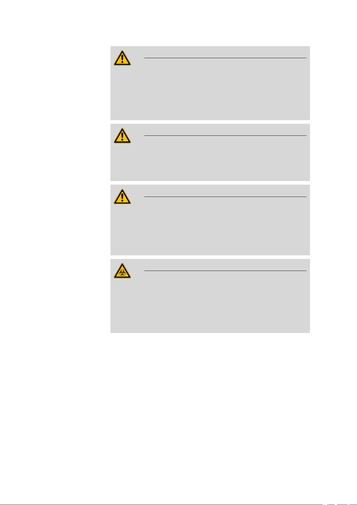
Caution
Please read through this documentation carefully before putting the
instrument into operation. The documentation contains information
and warnings which have to be followed by the user in order to ensure
safe operation of the instrument.
1 Introduction
1.2.1 Symbols and conventions
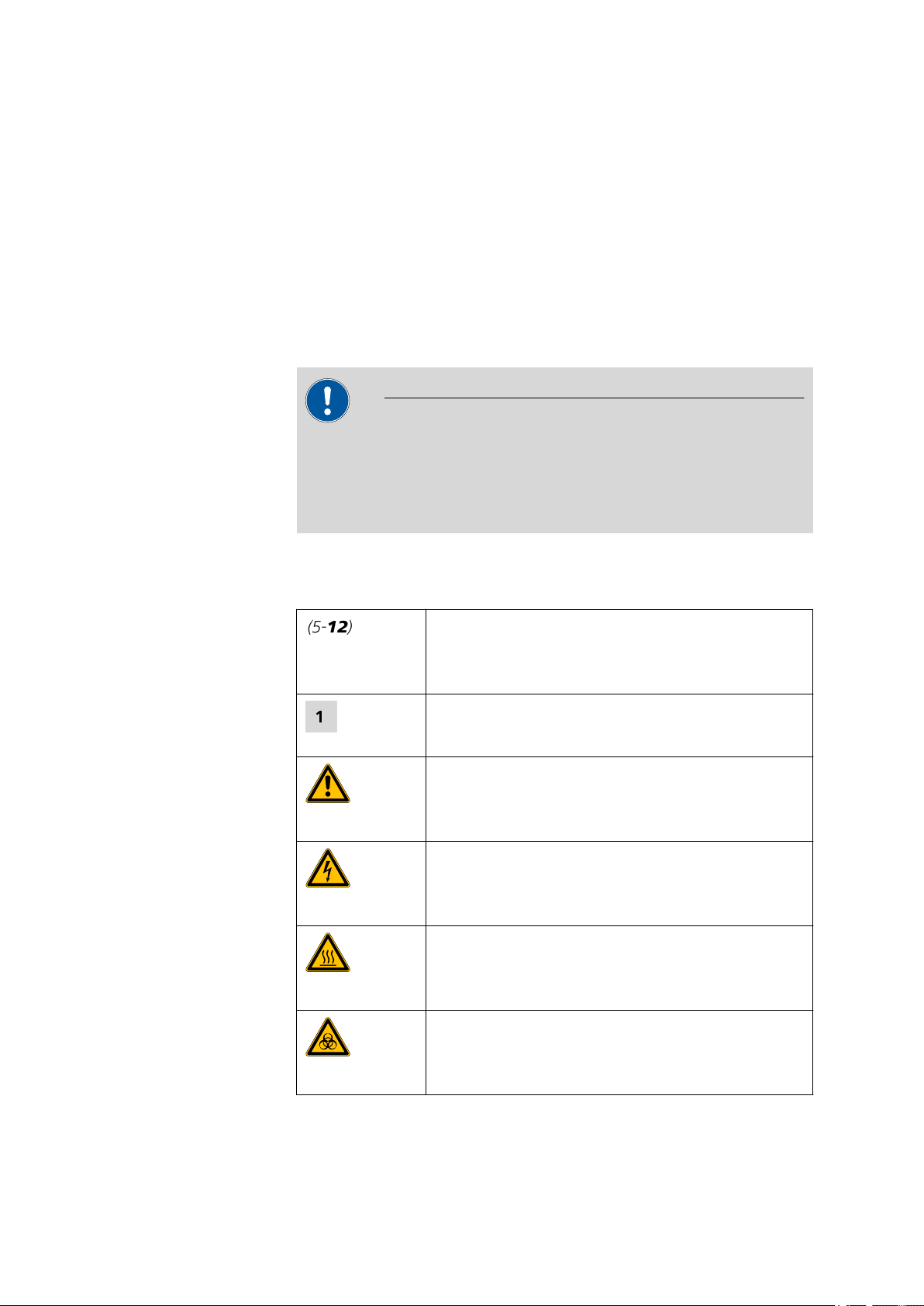
The following symbols and styles are used in this documentation:
Cross-reference to figure legend
The first number refers to the figure number, the
second to the instrument part in the figure.
Instruction step
Carry out these steps in the sequence shown.
Warning
This symbol draws attention to a possible life hazard
or risk of injury.
Warning
This symbol draws attention to a possible hazard due
to electrical current.
Warning
This symbol draws attention to a possible hazard due
to heat or hot instrument parts.
864 Robotic Balance Sample Processor
Warning
This symbol draws attention to a possible biological
hazard.
■■■■■■■■
3
Page 12
1.3 Safety instructions
1.3 Safety instructions
1.3.1 General notes on safety
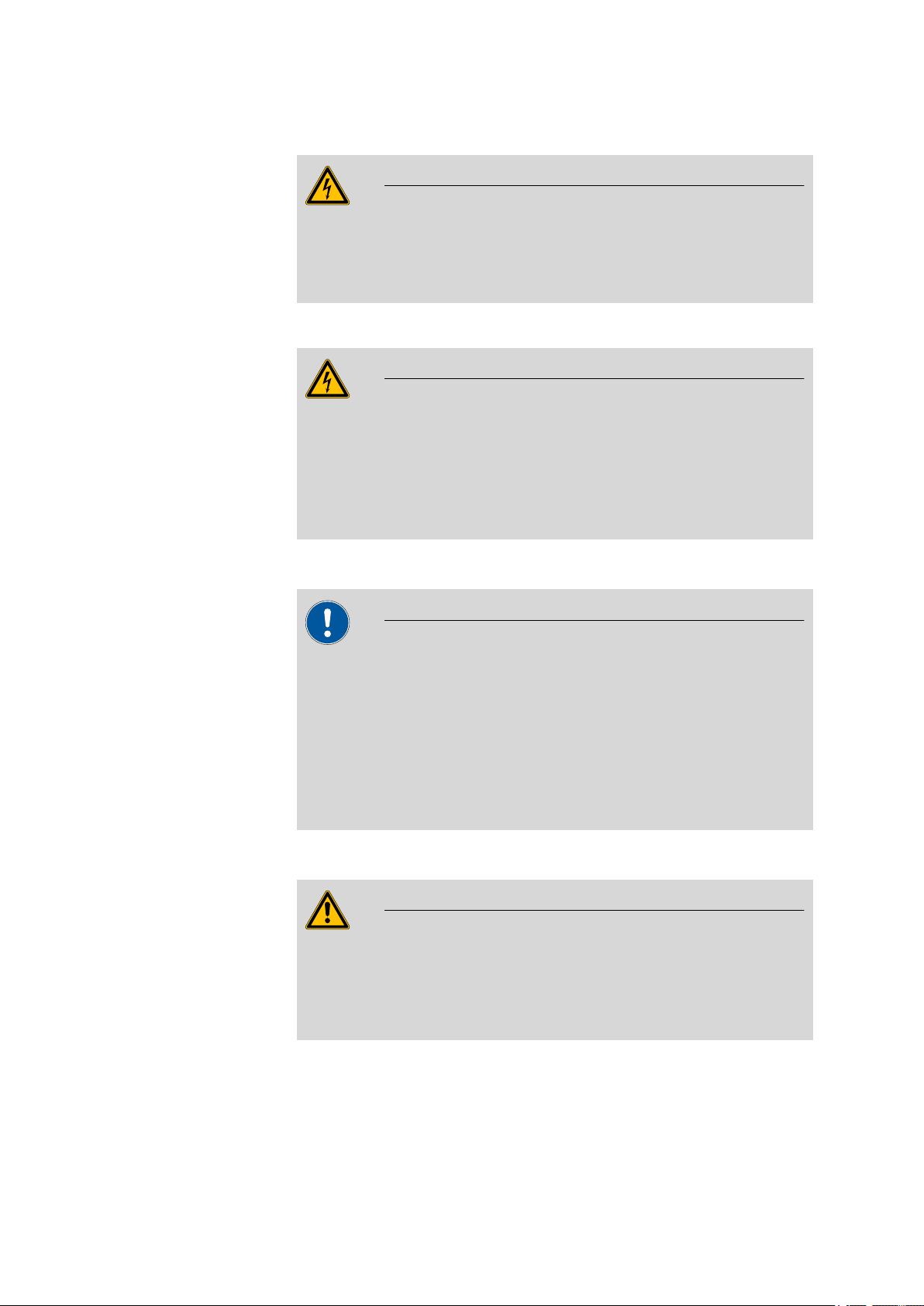
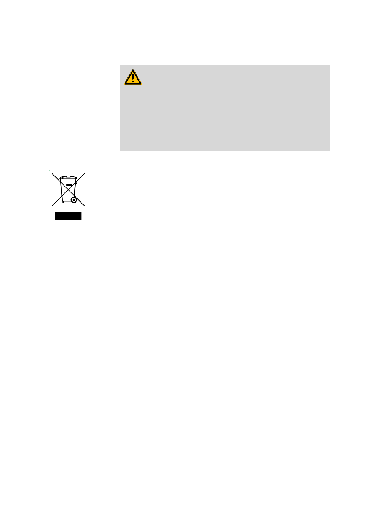
Warning
This instrument may only be operated in accordance with the specifications in this documentation.
This instrument has left the factory in a flawless state in terms of technical
safety. To maintain this state and ensure non-hazardous operation of the
instrument, the following instructions must be observed carefully.
■■■■■■■■■■■■■■■■■■■■■■
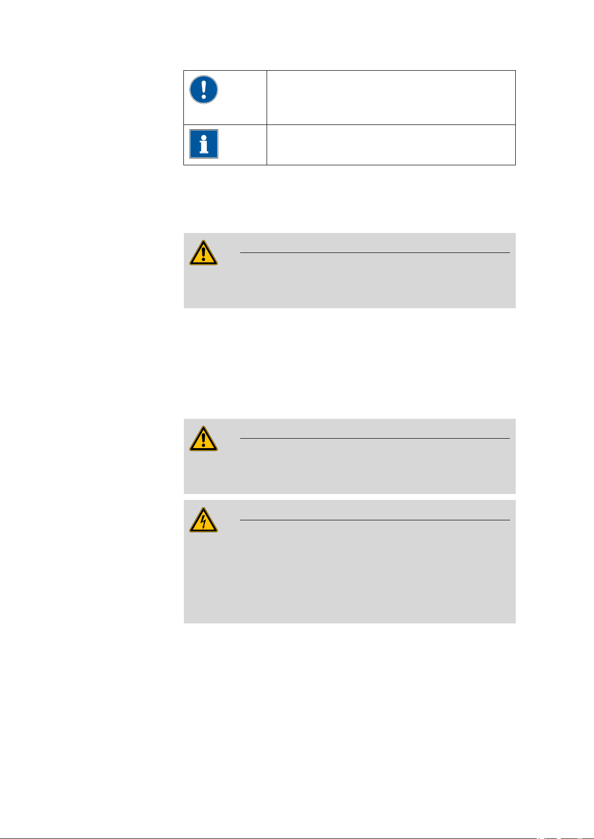
Caution
This symbol draws attention to a possible damage of
instruments or instrument parts.
Note
This symbol marks additional information and tips.
1.3.2 Electrical safety
The electrical safety when working with the instrument is ensured as part
of the international standard IEC 61010.
Only personnel qualified by Metrohm are authorized to carry out service
work on electronic components.
Never open the housing of the instrument. The instrument could be
damaged by this. There is also a risk of serious injury if live components
are touched.
There are no parts inside the housing which can be serviced or replaced
by the user.
Warning
Warning
■■■■■■■■
4
864 Robotic Balance Sample Processor
Page 13
■■■■■■■■■■■■■■■■■■■■■■
1 Introduction
Mains voltage
Warning
An incorrect mains voltage can damage the instrument.
Only operate this instrument with a mains voltage specified for it (see
rear panel of the instrument).
Protection against electrostatic charges
Warning
Electronic components are sensitive to electrostatic charges and can be
destroyed by discharges.
Always pull the mains cable out of the mains connection socket before
connecting or disconnecting electrical appliances on the rear panel of
the instrument.
1.3.3 Tubing and capillary connections
Caution
Leaks in tubing and capillary connections are a safety risk. Tighten all
connections well by hand. Avoid applying excessive force to tubing
connections. Damaged tubing ends lead to leakage. Appropriate tools
can be used to loosen connections.
Check the connections regularly for leakage. If the instrument is used
mainly in unattended operation, then weekly inspections are mandatory.
1.3.4 Personnel safety
Warning
Wear protective goggles and working clothes suitable for laboratory
work while operating the 864 Robotic Balance Sample Processor. It is
also advisable to wear gloves when caustic liquids are used or in situations where glass vessels could break.
864 Robotic Balance Sample Processor
■■■■■■■■
5
Page 14
1.3 Safety instructions
■■■■■■■■■■■■■■■■■■■■■■
Warning
Always install the safety shield supplied with the equipment before
using the instrument for the first time. Pre-installed safety shields are
not allowed to be removed.
The 864 Robotic Balance Sample Processor may not be operated without a safety shield!
Warning
Personnel are not permitted to reach into the working area of the
instrument while operations are running!
A considerable risk of injury exists for the user.
Warning
In the event of a possible blockage of a drive, the mains plug must be
pulled out of the socket immediately. Do not attempt to free jammed
sample vessels or other parts while the device is switched on. Blockages
can only be cleared when the instrument is in a voltage-free status; this
action generally involves a considerable risk of injury.
Warning
The 864 Robotic Balance Sample Processor is not suitable for utilization
in biochemical, biological or medical environments in its basic equipment version.
Appropriate protective measures must be implemented in the event
that potentially infectious samples or reagents are being processed.
■■■■■■■■
6
864 Robotic Balance Sample Processor
Page 15
■■■■■■■■■■■■■■■■■■■■■■
1.3.5 Flammable solvents and chemicals
Warning
All relevant safety measures are to be observed when working with
flammable solvents and chemicals.
■ Set up the instrument in a well-ventilated location.
■ Keep all sources of flame far from the workplace.
■ Clean up spilled fluids and solids immediately.
■ Follow the safety instructions of the chemical manufacturer.
1.3.6 Recycling and disposal
This product is covered by European Directive 2002/96/EC, WEEE – Waste
from Electrical and Electronic Equipment.
The correct disposal of your old equipment will help to prevent negative
effects on the environment and public health.
1 Introduction
More details about the disposal of your old equipment can be obtained
from your local authorities, from waste disposal companies or from your
local dealer.
864 Robotic Balance Sample Processor
■■■■■■■■
7
Page 16
2.1 Front and rear
1
2
3
4
5
6
7
8
9
10
11
12
13
14
15
2 Overview of the instrument
2.1 Front and rear
■■■■■■■■■■■■■■■■■■■■■■
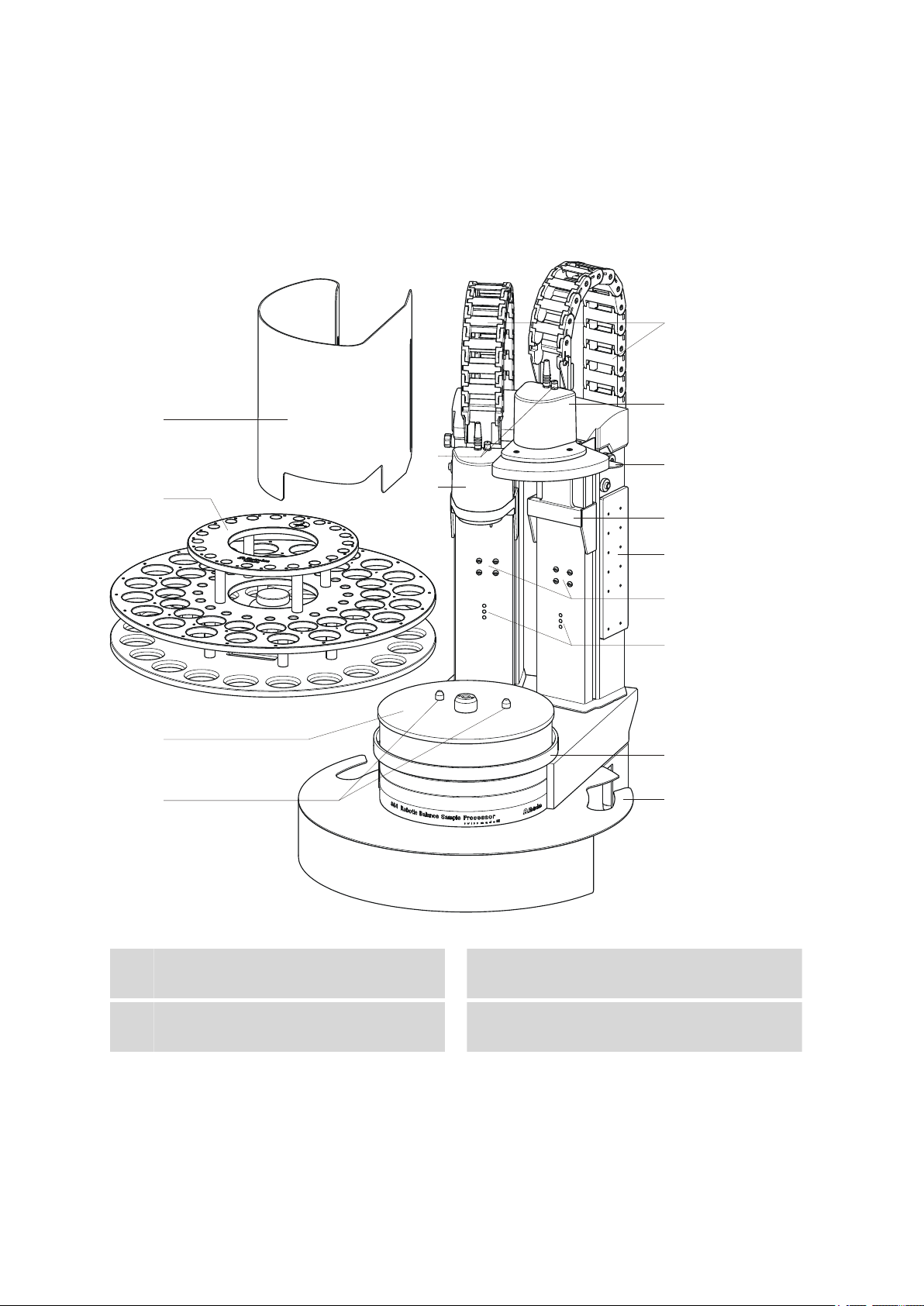
Figure 1 Front 864 Robotic Balance Sample Processor
Safety shield (6.2751.160)
1
For the tower 2 (left).
Turntable
3
Sample rack (6.2068.010)
2
Guide bolts
4
For the sample rack.
■■■■■■■■
8
864 Robotic Balance Sample Processor
Page 17
■■■■■■■■■■■■■■■■■■■■■■
1
2
3
4
5
2 Overview of the instrument
Connector for a robotic arm sensor
5
Only necessary when using a robotic arm
with beaker sensor.
Guide chain
7
For tubings and cables.
Robotic arm reinforcement
9
(6.2058.040)
Fastening plate (6.2058.050)
11
For mounting the deflector.
Beaker sensor
13
For the recognition of a sample vessel.
Housing
15
With recesses for mounting a balance.
786 Swing Head (2.786.0040)
6
Drive for a 6.1462.XXX robotic arm.
786 Swing Head (2.786.0140)
8
With reinforcement plate.
Lift 1 with tower extension
10
(6.2058.010)
Fastening screws for a retaining plate
12
Only necessary when using piercing needles.
Assembly rail
14
For mounting a rinsing station and other
accessories.
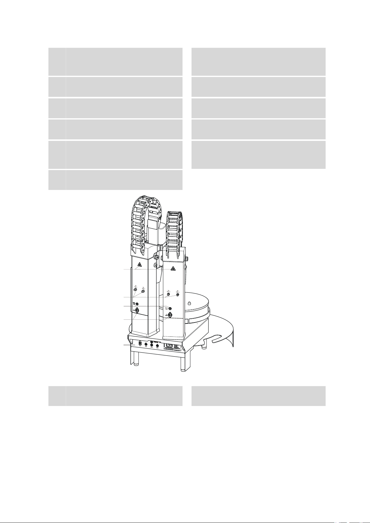
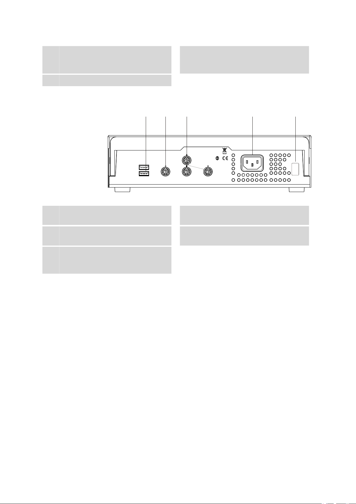
Figure 2 Rear 864 Robotic Balance Sample Processor
Warning symbols
1
(see Chapter 1.3.4, page 5)
864 Robotic Balance Sample Processor
Pump connectors
2
With threaded plug, for external pumps.
■■■■■■■■
9
Page 18
2.2 Rear panel
USB 2
USB 1
Contr.
MSB 1
MSB 2
MSB 3
Made by Metrohm
Herisau Switzerland
P: 115W U: 100 - 240 V f: 50 - 60 Hz
WARNING - Fire Hazard -
For continued protection replace only
with the same type and rating of fuse
Nr.
1 2 3 4 5
■■■■■■■■■■■■■■■■■■■■■■
Swing Head connectors
3
For the robotic arm drive (786 Swing Head).
Rear panel with connectors
5
2.2 Rear panel
Figure 3 Connector strip
USB connectors
1
Stirrer connectors
4
For rod stirrer (802 Stirrer) and magnetic stirrer (741 Stirrer).
Controller connector
2
For the connection to the PC
MSB connector
3
For dosing devices, stirrers, etc.
Type plate
5
Contains specifications concerning mains
voltage and serial number.
2.3 The Swing Head
The 786 Swing Head is an auxiliary drive for the Metrohm Sample Processor series, e.g. the 864 Robotic Balance Sample Processor. It is a highprecision motor drive that makes it possible to move to any point position
on a sample rack. Even positions outside of the sample rack are reachable
when a suitable robotic arm is used.
Two Swing Heads are already pre-installed on the 864 Robotic Balance
Sample Processor.
Left-swinging or right-swinging models are available as different types of
robotic arms. "Left-swinging" means swinging from the initial position
(pointing towards the middle of the rack) outwards to the left.
The following diagram illustrates the most important configuration data
that needs to be set in the control software to ensure correct usage of a
robotic arm (left-swinging, here).
Mains connection
4
10
■■■■■■■■
864 Robotic Balance Sample Processor
Page 19

■■■■■■■■■■■■■■■■■■■■■■
2
3
4
5
1
2 Overview of the instrument
Figure 4 Swing Head - Configuration data
Swing axis
1
This runs through the middle of the Swing
Head drive.
Source axis
3
This runs from the swing axis to the midpoint of the sample rack and marks the initial position of the robotic arm.
Max. swing angle
5
This stands for the swing range that the
robotic arm can reach. The range runs from
the source axis to the maximum possible
robotic arm position.
The configuration data of a robotic arm can be read on its underside or
can be found on an accompanying sheet. Before mounting a robotic arm,
the configuration data must be set in the control software.
Swing radius
2
This is determined by the length of the
robotic arm. The radius runs from the axis of
rotation to the midpoint of the tip of the
robotic arm.
Swing offset
4
This determines the 0° position of the
robotic arm.
864 Robotic Balance Sample Processor
■■■■■■■■
11
Page 20
2.4 Sample racks
1
2 3 4
If a Swing Head drive is mounted with a 6.2058.020 adapter in order to
use racks smaller than intended, then the axial distance must be modified in the configuration of the control software. The corresponding data
can be found on the accompanying sheet of the 6.2058.020. The axial
distance refers to the distance of the swing axis (see figure) and of the axis
of rotation (middle point) of the sample rack.
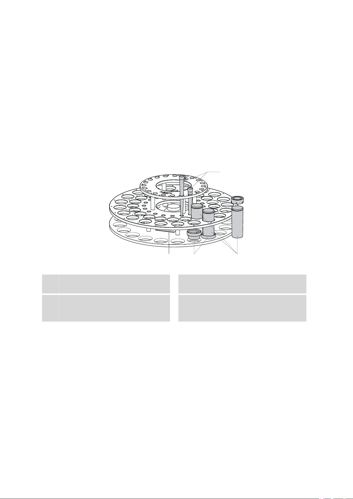
2.4 Sample racks
A sample rack is a turntable that acts as a receptacle for sample vessels.
Various types of sample racks are available for different numbers and
types of sample vessels.
The 864 Robotic Balance Sample Processor requires sample racks with up
to a maximum of 48 cm diameter.
■■■■■■■■■■■■■■■■■■■■■■
Pipetting tips 10 mL
1
Weighing pans
3
Made from PTFE/graphite.
Figure 5 6.2068.010 Sample rack
Magnet holder
2
Contains the rack code.
Sample vessel 120 mL (6.1459.300)
4
Made of PP, with cover for sampling and
transport.
Other user-defined racks can be supplied upon request and the required
rack data can be loaded and configured in the control software. Any
arrangement of rack positions is possible.
Magnet codes
Every single sample rack can be unambiguously identified by means of a
magnet code. The Sample Processor can thus recognize automatically
which rack is in place.
When replacing a rack, this should first be returned to starting position
using the Rack initialization function (see "Manual Control" in the control software). This will enable an unambiguous recognition of the rack
■■■■■■■■
12
864 Robotic Balance Sample Processor
Page 21

■■■■■■■■■■■■■■■■■■■■■■
2 Overview of the instrument
and thus the correct positioning of the beaker. A positioning table is
assigned to each rack type in which each rack position is defined.
864 Robotic Balance Sample Processor
■■■■■■■■
13
Page 22
3.1 Setting up the instrument
3 Installation
3.1 Setting up the instrument
3.1.1 Packaging
The instrument is supplied in highly protective special packaging together
with the separately packed accessories. Keep this packaging, as only this
ensures safe transportation of the instrument.
3.1.2 Checks
Immediately after receipt, check whether the shipment has arrived complete and without damage by comparing it with the delivery note.
3.1.3 Location
The instrument has been developed for operation indoors and may not be
used in explosive environments.
■■■■■■■■■■■■■■■■■■■■■■
Place the instrument in a location of the laboratory suitable for operation
and free of vibrations, if possible protected from corrosive atmospheres
and contamination by chemicals.
Air currents can disrupt the weighing sequences. Do not place the device
in a draft or in the vicinity of an air-conditioning unit.
The instrument should be protected against excessive temperature fluctuations and direct sunlight.
3.2 Preparing the Sample Processor
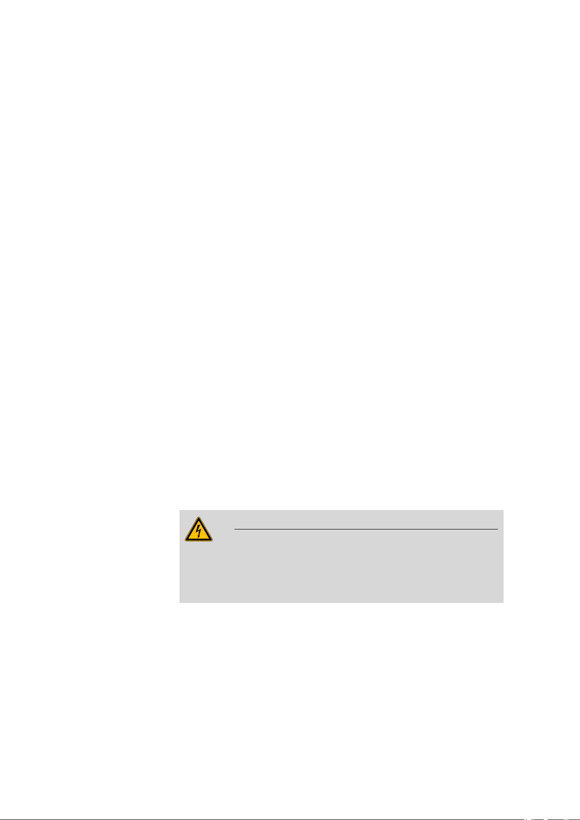
3.2.1 Connecting a mains cable
Warning
This instrument must not be operated except with the mains voltage
specified for it (see rear panel of the instrument).
Protect the connection sockets against moisture.
■■■■■■■■
14
864 Robotic Balance Sample Processor
Page 23
■■■■■■■■■■■■■■■■■■■■■■
P: 115W U: 100 - 240 V f: 50 - 60 Hz
Nr.
Figure 6 Connecting the mains cable
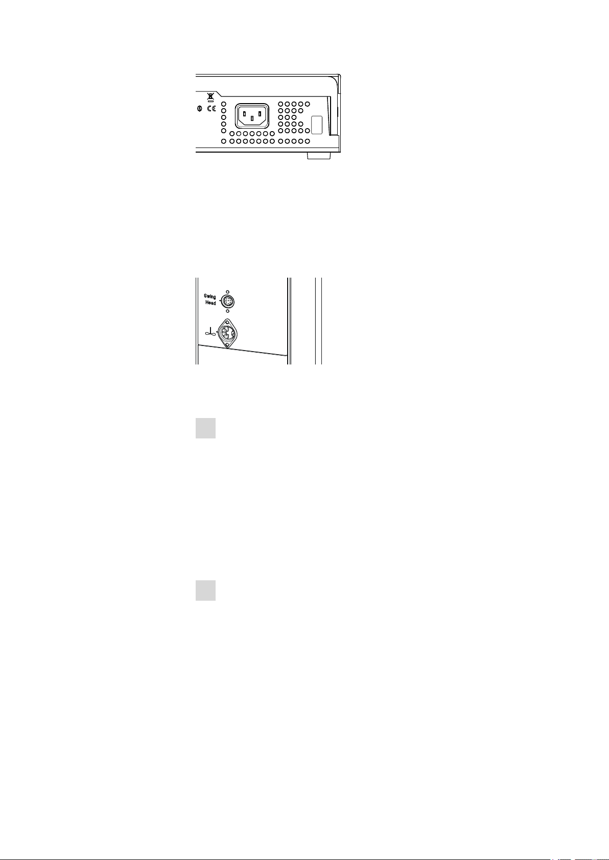
3.2.2 Connecting the Swing Head
Take care to ensure that the Swing Head is connected before the instrument is started up. Check the connection cable.
The connection socket (Mini DIN) for the Swing Head drive is each located
on the rear of the tower next to the stirrer connector.
3 Installation
Figure 7 Connecting Swing Head
If the Swing Head is not connected, connect it as follows:
1
Plug in the cable
■ Guide the connection cable of the Swing Head through the guide
chain of the tower (see Chapter 3.3, page 17).
■ Plug the Mini DIN plug into the socket 'Swing Head'.
3.2.3 Mounting the deflector and collection container
When using pipetting tips, injection needles and disposable filters, these
need to be stripped off the robotic arm again afterwards. For this purpose, a deflector and a collection container are mounted on the fastening
plate on the right-hand side of the tower 1. Proceed as follows:
1
Mount the deflector
■ Screw the 6.2058.070 deflector tightly to the fastening plate with
the screws and washers supplied.
We recommend selecting the highest position on the fastening
plate. For positioning, the deflector can be shifted laterally as
required.
864 Robotic Balance Sample Processor
■■■■■■■■
15
Page 24

3.2 Preparing the Sample Processor
6.2058.070
6.2057.150
■■■■■■■■■■■■■■■■■■■■■■
Figure 8 Mounting the deflector
2
Mount the holder
■ Screw the 6.2057.150 holder for the collection container to the
fastening plate tightly with the aid of the screws and washers
supplied.
We recommend selecting the lowest position on the fastening
plate.
Figure 9 Mounting the holder for the collection container.
3
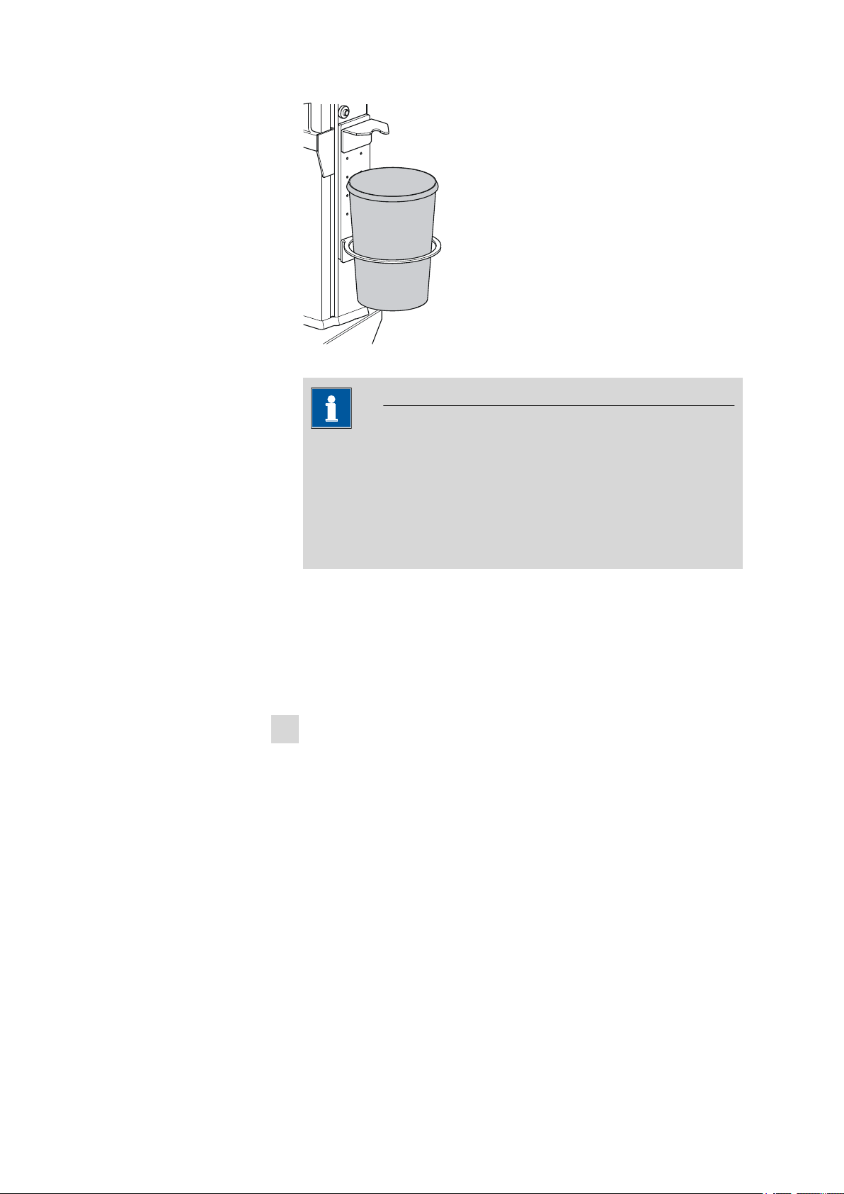
Mount the collection container
■ Guide the 6.1625.010 collection container without cover into the
holder.
■■■■■■■■
16
864 Robotic Balance Sample Processor
Page 25
■■■■■■■■■■■■■■■■■■■■■■
6.1625.010
3 Installation
Figure 10 Mounting the collection container for the pipetting tips
Note
The collection container seal is designed as a safety seal. If you are
processing highly toxic samples, you can hermetically seal off the
vessel with the contaminated pipetting tips and thus forward them
securely packaged for disposal. If the cover is pressed firmly onto
the vessel, then it cannot be reopened unless considerable effort is
applied!
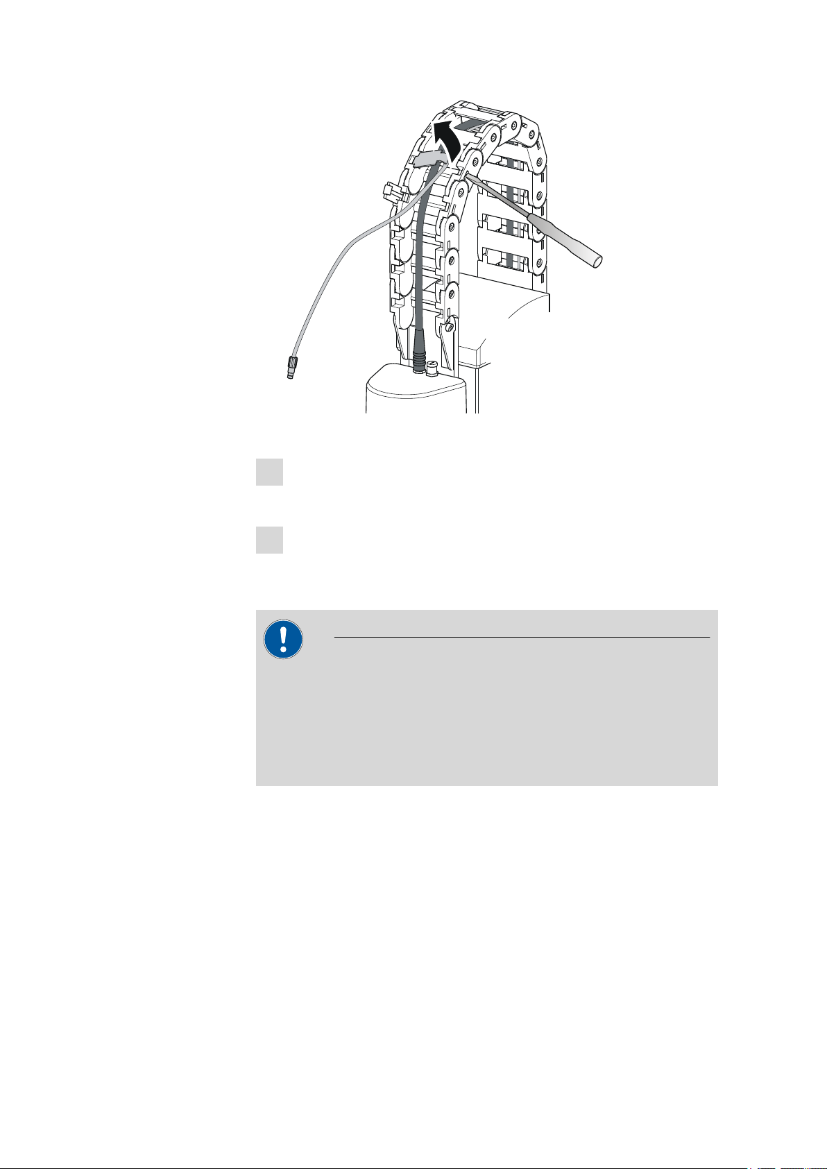
3.3 Guide chain for cables and tubing
Tubings and cables can be placed into the guide chain.
You can open the individual chain links with a screwdriver as follows.
1
Open the guide chain
■ Insert a screwdriver into the groove located on the side of a chain
link.
■ Loosen the clip with a forceful leverage movement.
■ Pull the clip out of the chain by hand.
■ Repeat the above actions for each chain link.
864 Robotic Balance Sample Processor
■■■■■■■■
17
Page 26
3.3 Guide chain for cables and tubing
■■■■■■■■■■■■■■■■■■■■■■
Figure 11 Guide chain - Opening chain links
2
Insert into the guide chain
■ Place the required tubings or cables into the guide chain.
3
Close the guide chain
■ Close the clip for each chain link again by hand and apply forceful
pressure to snap them into place.
Caution
Take care to ensure when mounting tubing and cables that there is no
traction on the drives while moving the lift or swiveling the robotic arm.
This could lead to overloading of and possible damage to the drive.
Remove the clips of the two lowest chain links when you install the
rinsing and aspiration tubing.
■■■■■■■■
18
864 Robotic Balance Sample Processor
Page 27
■■■■■■■■■■■■■■■■■■■■■■
6.2151.000
USB 2
USB 1
Contr.
MSB 2
3.4 Connecting a computer
The 864 Robotic Balance Sample Processor requires a USB connection to a
computer in order to be able to be controlled by a PC software. When a
6.2151.000 controller cable is used, the instrument can be connected
directly, either to a USB socket on a computer, to a connected USB hub or
to a different Metrohm control instrument.
Cable connection and driver installation
A driver installation is required in order to ensure that the 864 Robotic Balance Sample Processor is recognized by the PC software. To accomplish
this, you must comply with the procedures specified. The following steps
are necessary:
1
Installing the software
■ Insert the PC software installation CD and carry out the installa-
tion program directions.
■ Exit the program if you have started it after the installation.
2
Establishing cable connections
■ Connect all peripheral devices to the instrument (see Chapter
3.21, page 59).
■ Connect the 864 Robotic Balance Sample Processor to the mains
supply if you have not already done this.
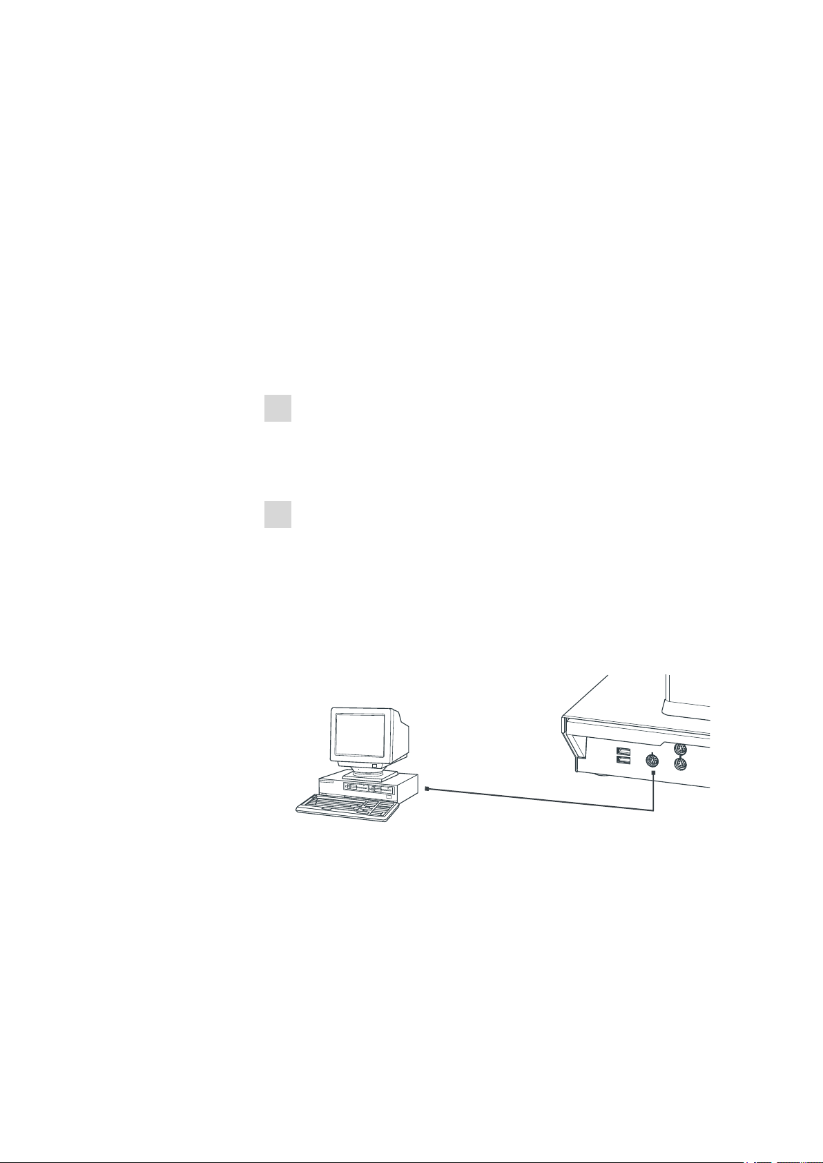
■ Connect the instrument to your computer through a USB connec-
tor (Type A) (see Instructions for Use for your computer). The
6.2151.000 cable is used for this purpose.
3 Installation
864 Robotic Balance Sample Processor
Figure 12 Connecting the computer
For Windows 2000: The instrument is recognized and the driver is
installed automatically.
For Windows XP: The instrument is recognized and the installation
assistant for the driver is started automatically. Select the option
"Install software automatically" and click on [Continue]. Exit the
assistant with [Finish].
■■■■■■■■
19
Page 28

3.5 Configuring instrument components
The plug on the instrument end of the 6.2151.000 controller cable is
protected with an anti-pull device to prevent the cable from being
pulled out accidentally. If you wish to pull out the plug, then you must
first retract the outer plug sleeve marked with arrows.
Registering and configuring the instrument in the PC software
The instrument must be registered in the configuration of your PC software. Once that has been done, you can then configure it according to
your requirements. Proceed as follows:
■■■■■■■■■■■■■■■■■■■■■■
For Windows Vista: The instrument is recognized and the installation assistant for the driver is started automatically. Select the option
"Find and install driver software". Agree to all subsequent requests.
The installation assistant will be exited automatically.
Note
1
Setting up the instrument
■ Start up the PC software.
The instrument is recognized automatically. The configuration dialog for the instrument is displayed.
■ Make configuration settings for the instrument and its connec-
tors.
More detailed information concerning the configuration of the instument can be found in the documentation for the respective PC software.
3.5 Configuring instrument components
3.5.1 Configuring robotic arms
Before mounting the robotic arms their configuration data must be
entered in the control software.
■■■■■■■■
20
864 Robotic Balance Sample Processor
Page 29
■■■■■■■■■■■■■■■■■■■■■■
Tower 1
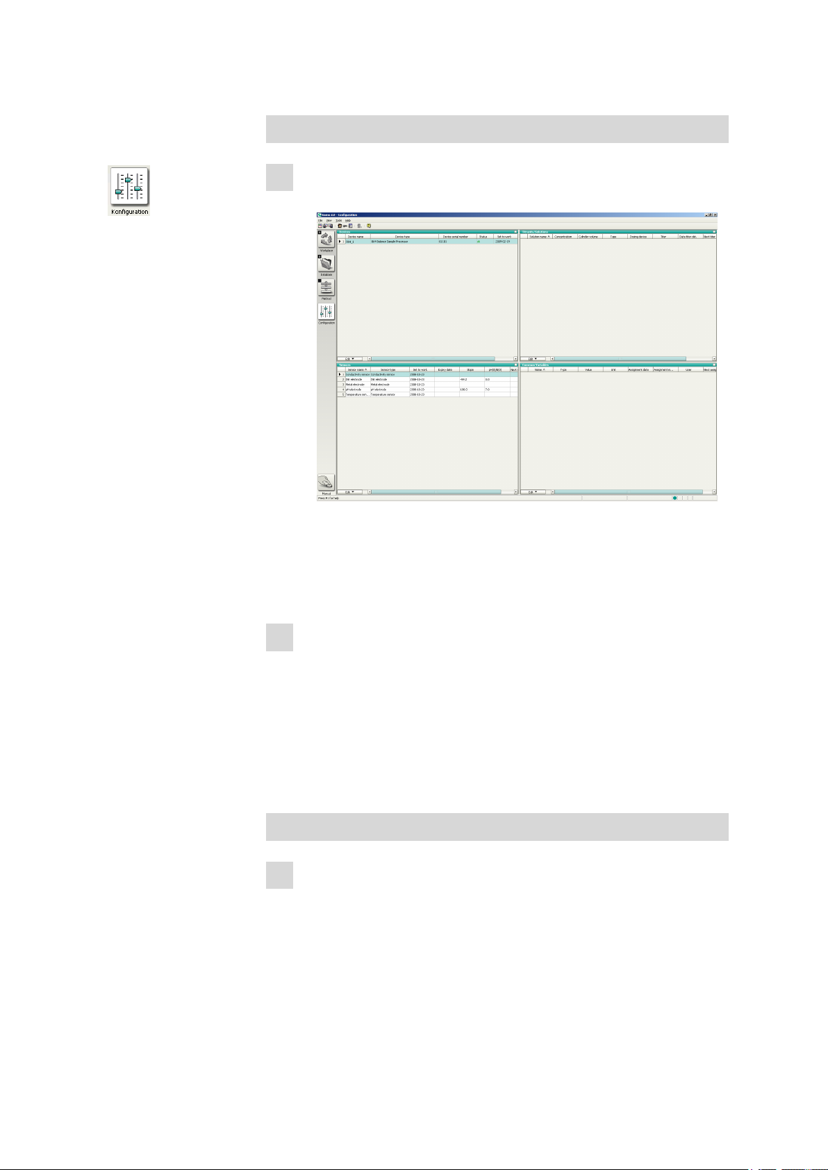
1
Open the robotic arm configuration
■ Click the Configuration icon.
3 Installation
■ Double-click the instrument name 864_1 in the Devices win-
dow.
■ In the properties window of the 864 Robotic Balance Sample Pro-
cessor under Tower 1, open the configuration of the Swing
Head.
2
Enter the configuration data
■ Enter the following data:
– Swing offset –8.6°
– Maximum swing range 122°
– Swing radius 149.8 mm
– Rotation offset 0.0°
– Swing direction –
■ Close the configuration window with [OK].
Tower 2
1
Open the robotic arm configuration
■ In the properties window of the 864 Robotic Balance Sample Pro-
cessor under Tower 2, open the configuration of the Swing
Head.
864 Robotic Balance Sample Processor
■■■■■■■■
21
Page 30
3.5 Configuring instrument components
2
Enter the configuration data
■ Enter the following data:
– Swing offset –8.0°
– Maximum swing range 105°
– Swing radius 110 mm
– Rotation offset 0.0°
– Swing direction +
3.5.2 Configuring the towers
Various lift positions must be defined before methods are created for the
864 Robotic Balance Sample Processor.
On Tower 1 settings are necessary for:
■ Lift position for picking up a pipetting tip
■ Lift position for aspirating and discharging sample liquid.
■ Robotic arm and lift positions for deflecting the pipetting tips.
On Tower 2 settings are necessary for:
■■■■■■■■■■■■■■■■■■■■■■
■ Lift position for titrating
■ Lift position for rinsing the titration head on the rack
or
■ Robotic arm and lift position for rinsing the titration head in the wash-
ing station
Tower 1
Configure the positions for tower 1:
1
Open the tower configuration
■ Click the Configuration icon.
■ Double-click the instrument name 864_1 in the Devices win-
dow.
■ Click the tab Tower 1.
2
Enter the configuration data
■ Enter the following settings:
– Max. stroke path 215 mm
– Swing position 136 mm
– External position 1, angle 127.9°
– External position 1, work position 136 mm
– External position 2, angle 138.2°
– External position 2, work position 129 mm
■■■■■■■■
22
864 Robotic Balance Sample Processor
Page 31

■■■■■■■■■■■■■■■■■■■■■■
Tower 2
Configure the positions for tower 2:
1
Open the tower configuration
■ Click the tab Tower 2.
2
Enter the configuration data
■ Enter the following settings:
– Max. stroke path 171 mm
– Swing position 0 mm
– External position 1, angle 120.5°
– External position 1, work position 151 mm
3.5.3 Configuring rack data
On the rack, reserved positions for rinsing beakers are necessary. These
can be defined in the rack data.
3 Installation
Rack data
1
Open the dialog window
■ Click the tab Rack.
■ Click the button Rack data.
The dialog window of the rack data is opened.
2
Define special beaker 1
■ Click Special beakers.
■ Select the first line for the Special beaker 1 and press [Edit].
■ Enter the following data:
– Rack position 57
– Work position Tower 2 170 mm
■ Close the dialog window with [OK].
3
Define special beaker 2
■ Select the second line for the Special beaker 2 and press [Edit].
■ Enter the following data:
– Rack position 58
– Work position Tower 2 170 mm
■ Close the dialog window with [OK].
864 Robotic Balance Sample Processor
■■■■■■■■
23
Page 32

3.5 Configuring instrument components
4
5
■■■■■■■■■■■■■■■■■■■■■■
Define special beaker 3
■ Select the third line for the Special beaker 3 and press [Edit].
■ Enter the following data:
– Rack position 59
– Work position Tower 2 148 mm
At this height, only the membrane and not the diaphragm
of the electrode should be immersed in the distilled water
in the rinsing beaker. Correct the filling volume of the water
if necessary.
■ Close the dialog window with [OK].
Define special beaker 4
■ Select the fourth line for the Special beaker 4 and press [Edit].
■ Enter the following data:
– Rack position 60
– Work position Tower 2 170 mm
■ Close the dialog window with [OK].
3.5.4 Defining lift positions
During the method run certain lift positions are repeatedly moved to.
These lift positions can be defined specifically for every single rack.
Lift configuration
1
Positions for lift 1
■ In the dialog window of the rack data click the tab Lift posi-
tions.
■ Under Tower 1 enter the following data:
– Work position 175 mm
– Rinse position 140 mm
– Shift position 0 mm
– Special position 197 mm
2
Positions for lift 2
■ Under Tower 2 enter the following data:
– Work position 170 mm
■ Close the dialog window with [OK].
3
Save the settings
■ Click the button [Initialize rack].
■■■■■■■■
24
All settings are saved and the rack is moved to the starting position.
864 Robotic Balance Sample Processor
Page 33

■■■■■■■■■■■■■■■■■■■■■■
3.6 Setting up the Swing Heads and robotic arms
3.6.1 Positioning the Swing Heads
In order to ensure that the robotic arms can be mounted as easily as possible, the Swing Head drives and/or the drive discs must be moved into a
defined position.
1
Initialize the Sample Processor
■ In tiamo™ click the hand symbol for manual control (on the left-
hand sidebar).
■ Under the entry Sample changer/864_1, select the Tower 1.
■ In the right-hand window click Initialize rack.
All instrument components are moved to the starting position.
2
Prepare the Swing Head
■ Click the tab Move.
■ Under Robotic arm position click the button Arrow left until
the drive disc of the Swing Head on tower 1 does not move any
more.
3 Installation
Now the robotic arms can be mounted.
864 Robotic Balance Sample Processor
■■■■■■■■
25
Page 34

3.6 Setting up the Swing Heads and robotic arms
6.1462.240
1
2
3.6.2 Mounting the robotic arms
Mounting the pipetting robotic arm
Mount the bent robotic arm 6.1462.240 on tower 1 as follows:
Figure 13 Mounting the bent robotic arm
1
Position the robotic arm
■ Align the robotic arm parallel to the left-hand edge of the Swing
Head reinforcement and graze it across the guide pins of the drive
disc of the Swing Head from below.
The correct position of the arm can be found in the previous illustration
■■■■■■■■■■■■■■■■■■■■■■
■■■■■■■■
26
Note
Take care to ensure that you do not twist the drive disc, thus causing pressure against the drive.
2
Fix the Swing Head
Screw the robotic arm to the Swing Head tightly with the screws and
washers provided.
Mounting the adapter
Pipetting tips can be taken up with the bent robotic arm. The
6.1808.250 adapter is used for this purpose. Mount it as follows:
864 Robotic Balance Sample Processor
Page 35

■■■■■■■■■■■■■■■■■■■■■■
6.1808.250
6.1808.000
6.1805.130
1
2
3
4
3 Installation
Figure 14 Mounting the pipetting tip adapter
1
Position the adapter
■ Loosen the screw and the washer of the adapter and guide the
adapter into the robotic arm head from below.
2
Fix the adapter
■ Screw the adapter tightly with the screw and the washer. If nee-
ded, tighten carefully with a wrench.
3
Attach the tubing adapter
■ Screw the 6.1808.000 tubing adapter (with 2x M6 inner thread,
supplied with the 6.1808.250 adapter) tightly onto the adapter.
4
Connect the tubing
■ Manually tighten the 6.1805.130 PTFE tubing (120 cm) to the
Mounting the robotic arm with the titration head
tubing adapter and place it into the guide chain of the tower.
After initialization, the drive disc of the Swing Head is positioned as
though the robotic arm were located in the outermost position.
Mount the 6.1462.260 robotic arm to tower 2 as follows:
864 Robotic Balance Sample Processor
■■■■■■■■
27
Page 36

3.6 Setting up the Swing Heads and robotic arms
1
2
3
6.1458.040
6.1462.260
Figure 15 Mount the robotic arm with the titration head
1
Mount the titration head insert
■ Place the 6.1458.040 titration head insert in the opening of the
robotic arm and screw tight with the supplied screws.
The arrow marking on the edge of the insert must be pointed
towards the Swing Head.
2
Position the robotic arm
■ Hold the robotic arm in such a way that the titration head faces
left and slip it over the guide pins of the drive disc from below.
■ While doing so, rotate the robotic arm outwards as far as possi-
ble, i.e. towards the tower - see previous figure.
■■■■■■■■■■■■■■■■■■■■■■
■■■■■■■■
28
Note
Take care to ensure that you do not twist the drive disc, thus causing pressure against the drive.
3
Fix the robotic arm
■ Screw the robotic arm to the Swing Head tightly with the screws
and washers provided.
864 Robotic Balance Sample Processor
Page 37

■■■■■■■■■■■■■■■■■■■■■■
6.1805.510
6.1805.060
6.1808.170
6.1812.000
1
2
3
4
3.7 Installing rinsing and aspiration equipment
Various tubings are necessary for rinsing the electrode and the dosing tips
as well as for aspirating the sample solution after the titration. First,
mount the tubings on the distributor.
Mounting the rinsing and aspiration tubings
Install the tubings as follows:
3 Installation
Figure 16 Mounting rinsing and aspiration tubings
1
Mount the rinsing tubings
■ Manually tighten the three 6.1805.060 FEP tubings (60 cm) in
the M6 bore holes of the distributor. Place the tubings into the
guide chain (see Chapter 3.3, page 17).
These are the feed lines for the rinsing nozzles.
2
Mount the aspiration tubing
■ Manually tighten the 6.1805.510 FEP aspiration tubing (60
cm) in the M8 bore hole of the distributor.
3
Mount the feed line for the rinsing liquid
■ Remove the union nut of the left-hand connector of the distribu-
tor and guide it over the end of a 6.1812.000 PTFE tubing. Pull
the end of the tubing over the connection nipple of the distributor and fasten in place with the union nut.
The tubing leads to the rinsing pump (pump 1 of the 843 Pump
Station) and can be cut to the correct length.
864 Robotic Balance Sample Processor
■■■■■■■■
29
Page 38

3.7 Installing rinsing and aspiration equipment
6.1808.170
1
2
The opening of the tubing may need to be widened with a sharp
object (e.g. with a Phillips screwdriver). A piece of sandpaper may
be used to get a better grip on the tubing.
4
Mount the outlet tubing
■ Remove the union nut of the right-hand connector of the distribu-
tor and guide it over the end of the 6.1812.000 PTFE tubing.
Pull the end of the tubing over the connection nipple of the distributor and fasten in place with the union nut.
The tubing leads to the aspiration pump (pump 2 of the 843
Pump Station) and can be cut to the correct length.
Mounting the distributor
■■■■■■■■■■■■■■■■■■■■■■
Note
30
■■■■■■■■
Figure 17 Mounting the distributor
Proceed as follows:
1
Remove a chain link
■ Remove the clip of the third chain link of the guide chain. Pry out
the clip with a screwdriver on both sides of the chain link, as
shown in the preceding illustration.
2
Insert the distributor
■ Apply strong pressure to insert the 6.1808.170 distributor
(with the tubing connected) into the open chain link.
3
Fix the rinsing tubings
■ Place the rinsing tubings into the guide chain.
864 Robotic Balance Sample Processor
Page 39

■■■■■■■■■■■■■■■■■■■■■■
1
2
3
6.1812.000
6.1812.000
3.8 Installing the washing station
If a more intensive rinsing procedure is required, then a washing station
(additional equipment 6.5622.000) can be used. This is not included in
the standard equipment. In addition, a second 843 Pump Station is
also required.
3 Installation
Figure 18 Mounting the washing station
In order to be able to mount the washing station, remove the sample rack
and the drip pan. Afterwards, proceed as follows:
1
Mount the washing station
■ Mount the washing station to the left next to tower 2 on the
assembly rail and screw it tightly.
2
Mount the outlet
■ Fasten a 6.1812.000 PTFE tubing to the lower tubing connector
of the washing station.
This is the outlet of the washing station.
■ Shorten the tubing to a suitable length and connect it to the aspi-
ration pump of the second 843 Pump Station.
3
Mount the feed line
■ Fasten a 6.1812.000 PTFE tubing to the upper tubing connector
of the washing station.
This is the feed line for the rinsing liquid.
864 Robotic Balance Sample Processor
■■■■■■■■
31
Page 40

3.9 Installing and connecting the pump
■ Shorten the tubing to a suitable length and connect it to the rins-
ing pump of the second 843 Pump Station.
3.9 Installing and connecting the pump
The installation of the 843 Pump Station is described in its manual.
Use the black 6.1826.160 pump tubing made of Viton® (trade name of
the DuPont Co.) that is supplied along with the 864 Robotic Balance Sample Processor. It has excellent resistance against hydrocarbons. A different
tubing material is to be used when other solvents are used. Clarify in such
cases the resistance of the material against the solvent being used.
Connecting the pump
■■■■■■■■■■■■■■■■■■■■■■
Figure 19 Connecting the pump
Connect the 843 Pump Sstation as follows:
1
Connect the connection cable
■ Plug the two threaded plugs of the 6.2141.300 connection
cable into the connection sockets Ext. pump 1 and Ext. pump
2 on the rear of the tower 2.
Correct alignment of the 3 contact pins must be observed.
■ Tighten the knurled screw at the front end of the plug by hand in
clockwise direction. This will secure the plug.
Connect the other end of the cable (9-pin D-Sub plug) to the socket
2
Remote 1 of the 843 Pump Station.
■■■■■■■■
32
864 Robotic Balance Sample Processor
Page 41

■■■■■■■■■■■■■■■■■■■■■■
1
2
3
6.1805.060
6.1805.510
6.1543.170
3.10 Equipping the titration head
Mounting the aspiration and rinsing tubings
3 Installation
Figure 20 Installing the rinsing tubings and the aspiration tip
Proceed as follows:
1
Connect the rinsing nozzles
■ Connect the three rinsing tubings that are already connected to
the Tower 2 distributor to the rinsing nozzles already mounted on
the titration head.
2
Insert the aspiration tip
■ Insert the 6.1543.170 aspiration tip into the opening left on
the front of the titration head.
3
Connect the aspiration tubing
■ Connect the 6.1805.510 aspiration tubing already connected to
the distributor with the aspiration tip.
864 Robotic Balance Sample Processor
■■■■■■■■
33
Page 42

3.10 Equipping the titration head
1
2
3
4
1.802.0010
6.1909.050
6.2104.030
6.1236.020
6.0229.100
6.1805.120
■■■■■■■■■■■■■■■■■■■■■■
Inserting the stirrer and the electrode, connecting the dosing tubings
The equipment of the titration head is completed as follows:
1
Insert the rod stirrer
■ Insert the rod stirrer (802 Stirrer) into the rear opening of the
titration head (at the arrow).
■ Insert the cable into the guide chain.
2
Mount the stirring propeller
■ Fasten the 6.1909.050 stirring propeller to the rod stirrer from
3
Insert the electrode
■ Insert the electrode (6.0229.100 Solvotrode) with a
below.
6.1236.020 SGJ sleeve into the titration head.
■■■■■■■■
34
864 Robotic Balance Sample Processor
Page 43

■■■■■■■■■■■■■■■■■■■■■■
4
Connect the dosing tubings
■ Connect the two 6.1805.120 dosing tubings of the titrant and
solvent to the pre-mounted dosing tips on the titration head.
3.11 Connecting the tower stirrer
A DIN socket for connecting a rod stirrer (802 Stirrer) or a magnetic stirrer (741 Stirrer) is located on the rear side of the tower.
Figure 21 Rod stirrer 802 Stirrer
3 Installation
Figure 22 Magnetic stirrer 741 Stirrer
Take care to observe correct orientation of the contact pins when plugging in the stirrer connection cable. The rib on the outside of the plug
must match the reference mark (on the left) on the socket.
Figure 23 Connecting the tower stirrer
Note
If an MSB stirrer is connected to the MSB1 or MSB2 socket, then the
stirrer connector on tower 1 or tower 2 cannot be used, because the
tower stirrers are internally controlled as well via MSB1 or MSB2.
864 Robotic Balance Sample Processor
■■■■■■■■
35
Page 44

3.12 Setting up the dosing devices and the titrator
1
2
3
4
5
6
■■■■■■■■■■■■■■■■■■■■■■
3.12 Setting up the dosing devices and the titrator
Supplied with the 864 Robotic Balance Sample Processor are three dosing
drives and a titrator. They can be set up in a compact arrangement
according to the following illustration.
Figure 24 Setting up the dosing devices and the titrator
Setting up the dosing units and the Dosinos
Proceed as follows:
1
Install the dosing unit for pipetting
■ Screw a 6.3032.220 20 mL dosing unit onto an empty
6.1608.030 clear glass bottle (1 L, with GL45 thread).
■ On Port 1, fasten the 6.1805.130 FEP tubing (120 cm) which
is connected to the pipetting tip adapter on tower 1, (see
"Mounting the adapter", page 26).
2
Mount the pipetting drive
■ Attach an 800 Dosino drive to the dosing unit.
■ Connect the connection cable to the connector MSB 1 of the
Sample Processor.
This is the pipetting drive. The Dosino pumps air in order to aspirate
the sample into the pipetting tip and then to expel this back out
again.
■■■■■■■■
36
864 Robotic Balance Sample Processor
Page 45

■■■■■■■■■■■■■■■■■■■■■■
3 Installation
3
Prepare the titrant
■ Fasten a filling tubing and an adsorber tube (filled with wadding)
on a 6.3032.220 20 mL dosing unit.
■ Screw a dosing unit on a bottle with titrant.
A 6.1608.030 clear glass bottle (1 L, with GL45 thread) can be
used.
■ On Port 1 of the dosing unit, fasten one of the 6.1805.130 FEP
tubings (100 cm), which are already mounted on the titration
head, see previous chapter.
4
Mount the drive for the titrant
■ Attach an 800 Dosino drive to the dosing unit.
■ Connect the connection cable to the connector MSB 1 of the
Titrando.
5
Prepare the solvent
■ Fasten a filling tubing and an adsorber tube (filled with wadding)
on a 6.3032.250 50 mL dosing unit.
■ Screw a dosing unit onto the 6.1608.070 clear glass bottle (2 L,
with GL45 thread) filled with solvent.
■ On Port 1 of the dosing unit, fasten one of the 6.1805.130 FEP
tubings (100 cm), which are already mounted on the titration
head, see previous chapter.
6
Mount the drive for the solvent
■ Attach an 800 Dosino drive to the dosing unit.
■ Connect the connection cable to the connector MSB 2 of the
864 Robotic Balance Sample Processor.
7
Connecting the electrode cable
■ Connect the 6.2104.030 electrode cable which is already con-
nected to the electrode to the connector Ind. on the rear of the
Titrando.
8
Connect the Titrando
■ Connect a 6.2151.000 connection cable to the Titrando (Con-
troller connector).
■ Connect the cable to a USB connector on the Sample Processor
or on the PC.
864 Robotic Balance Sample Processor
After that, the Titrando is recognized by the tiamo™ software and
can be added to the device table. The same applies for the dosing
■■■■■■■■
37
Page 46

3.13 Installing the balance and the ionizer
1
2
units and their solutions. They can also be added to the solution
table and be configured there.
3.13 Installing the balance and the ionizer
Preparing the balance
Various accessory parts are supplied with the balance and are necessary
for the installation.
■■■■■■■■■■■■■■■■■■■■■■
1
Mounting the weighing column
■ Carefully introduce the weighing column into the balance from
above.
2
Fixing the weighing column
■ Guide the associated fixing ring over the column and screw it
tightly.
Leveling and connecting the balance
The balance must be leveled prior to installation. The cable for the balance
must be connected before the balance is brought into position.
Proceed as follows:
1
Leveling the balance
■ Rotate the two foot screws of the balance until the air bubble in
the spirit level (on the rear side of the balance) comes to rest in
the inner circle of the spirit level.
■■■■■■■■
38
864 Robotic Balance Sample Processor
Page 47

■■■■■■■■■■■■■■■■■■■■■■
1
2
3
3 Installation
2
Connect the cable
■ Connect the mains cable and the RS 232 cable (with RJ-45 plug)
to the rear side of the balance.
■ Fasten the grounding cable to the rear side of the balance.
■ Pull the cable through under the housing of the Sample Processor
from the right and guide it to the rear.
Positioning the balance
The balance provided comes equipped with a clamping ring and a weighing plunger. The weighing plunger may not be attached at the time of the
installation. Proceed as follows:
Figure 25 Installing the balance
1
Position the clamping ring
■ Slightly loosen the clamping ring.
■ Guide the clamping ring over the weighing column.
2
Position the balance
■ Slide the balance from the right-hand side underneath the hous-
ing of the 864 Robotic Balance Sample Processor.
The clamping ring must fit into the recess of the housing in such a
way that the position of the balance can be readily fastened into
place with the clamping ring.
Do not tighten the clamping ring too firmly. The position of the
balance needs to be finely aligned later on.
864 Robotic Balance Sample Processor
■■■■■■■■
39
Page 48

3.13 Installing the balance and the ionizer
3
■■■■■■■■■■■■■■■■■■■■■■
Connect the cables
■ Connect the ground cable for the balance to the metal clip at the
underside of the housing of the Sample Processor.
The clip is located on the rear part of the bottom of the housing.
■ Connect the RS-232 connection cable of the balance to the
COM1 connector of the PC.
■ Connect the mains cable with the mains adapter of the mains
supply.
Note
Afterwards, check once again to see if the balance is still leveled.
For this, use the supplied 6.2831.000 inspection mirror. This
makes it possible to read off the spirit level of the balance, even if
it is now located under the Sample Processor.
Setting the interface parameters
The parameters of the data transmission between balance and PC must
match on both devices.
We recommend using the following parameters:
■ Baud rate 9600
■ Data bit 8
■ Parity None
■ Stop bit 1
■ Handshake None
1
Set the RS-232 parameters of the balance
Setting the parameters above is described in the manual of the balance.
2
Register the balance in tiamo
■ In the tiamo™ software, click the symbol Configuration.
■ In the device table click [Edit] and select New
■ Under Balances, select the balance type Precisa and click [OK].
The properties window of the balance is displayed.
■ Enter the serial number of the balance.
This is necessary to unambiguously identify the device.
3
Set the RS-232 parameters
■ Click the tab RS 232.
■■■■■■■■
40
864 Robotic Balance Sample Processor
Page 49

■■■■■■■■■■■■■■■■■■■■■■
6.2057.160
1
2
3
3 Installation
■ Under COM Port, select the connector on the PC the connection
cable was connected to.
■ Enter the values listed above as RS-232 parameters.
■ Click [Connect].
The dialog window Establish connection is displayed.
■ Press the [Print] key on the balance.
The data sent by the balance is displayed.
■ Close the dialog window with [OK].
The input fields in the properties window are now locked. This
means that the connection between balance and PC has been
established.
■ Close the properties window with [OK].
Installing the ionizing bar
In order to eliminate electrostatic loads while weighing, an ionizing bar
must be installed as close to the balance as possible. Proceed as follows:
Figure 26 Installing the ionizing bar
1
2
864 Robotic Balance Sample Processor
Fasten the holder
■ Fasten the 6.2057.160 holder on the assembly rail with the aid of
a hexagon key.
The position must be selected in such a way that the recess of the
holder surrounds the weighing column.
Insert the screws
■ Insert the two accompanying screws from above into the holding
rail of the ionizing bar.
■■■■■■■■
41
Page 50

3.14 Connections
T1 T2
864
809
800
800
843
SW
P1
P2
S
T
P
1 2
3
4
5
6
7
3
Fasten the ionizing bar
■ Fasten the ionizing bar to the holder as shown in the preceding
4
Connect the cables
■ Connect the cable of the ionizing bar to the control device.
■ Connect the control device to the mains supply.
The ionizer must be switched on by hand before a determination series.
3.14 Connections
■■■■■■■■■■■■■■■■■■■■■■
illustration and fix it in place with the two accompanying hexagon
nuts.
Note
The following figures show all necessary cable and tubing connections as
an overview.
3.14.1 Tubing connections
Figure 27 Tubing
Waste
1
6.1812.000 PTFE tubing.
Waste canister W — 843 pump 2
Aspiration tubing
3
6.1812.000 PTFE tubing.
843 pump 2 — 864 distributor, connector
on the right
Solvent
2
6.1812.000 PTFE tubing.
Supply canister S — 843 pump 1
Rinsing tubing
4
6.1812.000 PTFE tubing.
843 pump 1 — 864 distributor, connector
on the left
42
■■■■■■■■
864 Robotic Balance Sample Processor
Page 51

■■■■■■■■■■■■■■■■■■■■■■
1
2
5 6
9
8 10
11
12
843
Ion
B
864
809
PC
tiamo
TM
800
800
T1 T2
USB
COM1
3 4
7
S
T
P
3 Installation
Pipetting tubing
5
6.1805.130 FEP tubing
800 Dosino (on empty bottle P) — 864
tower 1, pipetting tip adapter
Solvent feed line (Solvent)
7
6.1805.120 FEP tubing
800 Dosino (solvent S) — 864 tower 2, dosing tip
3.14.2 Cable connections
Titration tubing
6
6.1805.120 FEP tubing
800 Dosino (titrant T) — 864 tower 2, titration tip
Figure 28 Cabling
Pump connection
1
6.2141.300 connection cable.
843 Pump Station (Remote 2) — 864:
tower 2 (pump 1 and pump 2)
Stirrer cable
3
Connection cable of the rod stirrer (802 Stirrer)
Connector on tower 2 (Stirrer)
Balance connection
5
RS-232 serial connection cable. Supplied
with the balance.
Balance (RS 232) — PC (COM1)
864 Robotic Balance Sample Processor
Ionizer connection
2
Ionizer (control device) — Ionizing bar
The connection cable is supplied with the
ionizer.
Swing Head cable
4
Connection cable of the 786 Swing Head
Connector on tower 2 (Swing Head).
USB connection
6
6.2151.000 controller cable (USB A-MiniDIN
8p)
864 (Controller) — PC (USB)
■■■■■■■■
43
Page 52

3.15 Mounting the drip pan
■■■■■■■■■■■■■■■■■■■■■■
Swing Head cable
7
Connection cable of the 786 Swing Head
Connector on tower 1 (Swing Head)
USB connection
9
6.2151.000 controller cable (USB A-MiniDIN
8p)
864 (USB) — Titrando (Controller)
Dosino connection (titrant T)
11
Dosino connection cable
Connector on Titrando (MSB 1)
3.15 Mounting the drip pan
Serious damage to the instrument or a danger to the user can occur if
chemicals or liquid samples are spilled. The use of the drip pan
6.2711.080 is recommended in order to avoid such incidents.
Sensor connection
8
Electrode cable (plug F2 m)
Sensor (on tower 2) — Titrando (Ind.)
Dosino connection (pipetting drive P)
10
Dosino connection cable
Connector on 864 (MSB 1)
Dosino connection (solvent S)
12
Dosino connection cable
Connection to the 864 Robotic Balance
Sample Processor (MSB 2)
■■■■■■■■
44
Figure 29 Mounting the tubing to the drip pan
First, fasten the tubing enclosed to the drainage nipple on the drip pan
and then guide the free end of the tubing into a waste container.
Install the drip pan as follows:
864 Robotic Balance Sample Processor
Page 53

■■■■■■■■■■■■■■■■■■■■■■
1
2
Figure 30 Installing the drip pan
1
Attach the drip pan
■ Place the drip pan on the assembly rail of the turntable in such a
way that the opening in the bottom of the pan can be guided
over the weighing column of the balance, see illustration.
2
Attach the weighing plunger
■ Provisionally screw the weighing plunger of the balance on the
weighing column at the lowest possible position.
3 Installation
864 Robotic Balance Sample Processor
■■■■■■■■
45
Page 54

3.16 Attaching the sample rack
6.2068.010
6.2067.100
1
2
3.16 Attaching the sample rack
■■■■■■■■■■■■■■■■■■■■■■
Figure 31 Attaching the sample rack
1
Attach the sample rack
■ Attach the 6.2068.010 sample rack on the turntable.
The guide bolts on the turntable must engage with the corresponding openings of the rack.
2
Attach the weighing pans
■ Insert the supplied 6.2067.100 weighing pans into all of the
openings of the lowest plate of the rack.
3.17 Adjusting the rack and the robotic arm
For picking up pipetting tips the adapter must be precisely positioned on
the robotic arm. In order to ensure this, it is necessary to align the sample
rack and the robotic arm precisely in relation to one another. The control
software tiamo™ allows the user to enter an offset in both robotic arm
and sample rack (rack table) configuration. This allows fine tuning to be
performed.
■■■■■■■■
46
The sample rack has a "positioning reticle". This is the adjusting position.
864 Robotic Balance Sample Processor
Page 55

■■■■■■■■■■■■■■■■■■■■■■
Figure 32 Positioning reticle on the sample rack
Defining the adjusting position
Proceed as follows:
1
Prepare
■ Put the sample rack in place.
■ Start tiamo™.
2
Open the configuration
3 Installation
■ Select the Configuration in tiamo™.
■ Double-click the device name 864_1.
■ Switch over to the Rack tab and click [Rack data] to open the
rack parameter settings.
■ Select the tab Special beaker.
864 Robotic Balance Sample Processor
■■■■■■■■
47
Page 56

3.17 Adjusting the rack and the robotic arm
The last position on the sample rack is conceived as Adjusting position.
3
Define the special beaker on the 6.2068.010 sample rack
■ Select the lowest line (Special beaker 16) and click [Edit].
■ Under Rack position, select 61.
■ Close the dialog window with [OK].
■ Close the rack data table with [OK].
Moving to the positioning reticle
■■■■■■■■■■■■■■■■■■■■■■
Proceed as follows:
1
Open the manual control
■ In the Manual control in tiamo™, click the tab Move.
2
Move to special beaker 16
■ Under Rack position, select the target position Special beaker
16 and click [Start].
It is also possible to specify the target position as absolute rack position. For the 6.2068.010 sample rack, the adjusting position is the
no. 61.
3
Move to the adjusting position
■ Unscrew the FEP tubing from the adapter on the robotic arm.
■ Insert the PEEK capillary supplied from above into the adapter.
The capillary must protrude below from the adapter by around
0.5 cm (see following illustration)
■ Under lift position enter 100 mm as target position and click
[Start].
■■■■■■■■
48
864 Robotic Balance Sample Processor
Page 57

■■■■■■■■■■■■■■■■■■■■■■
3 Installation
■ Move the lift further downwards, millimeter by millimeter, until
the robotic arm with the adapter is located precisely above the
positioning reticle.
Figure 33 Adjusting the rack and the robotic arm
The positioning reticle
The positioning reticle shows the directions of movement for the rack (R)
and the Swing Head (S). The scale lines stand for approximately 0.5° rotation angle or swing angle deviation.
Determine the deviation of the adapter tip from the middle of the positioning reticle. You can make the corresponding corrections in the
tiamo™ configuration afterwards.
Correcting the swing offset
If there is a deviation on the S line, then proceed as follows:
1
Open the robotic arm configuration
■ Select the Configuration in tiamo™.
■ Double-click the device name 864_1.
■ Click the tab Tower 1.
■ Click [Configuration] to open the settings of the robotic arm.
■ Confirm the safety prompt by clicking [Yes].
864 Robotic Balance Sample Processor
■■■■■■■■
49
Page 58

3.17 Adjusting the rack and the robotic arm
2
Correct the offset
■ Correct the value for the Swing offset according to the observed
■ Close the robotic arm configuration and the Sample Processor
3
Check the position
■ In the manual control, select the same rack position again and
■■■■■■■■■■■■■■■■■■■■■■
deviation from the positioning reticle.
One tick mark corresponds to approximately 0.5°.
properties dialog each with [OK].
lower the lift down to the positioning reticle.
Now the adapter tip with the capillary should point to the middle of
the positioning reticle. If this is not the case, then an additional correction must be made and the rack offset needs to be corrected.
Correcting the rack offset
If there is a deviation on the R Line, proceed as follows:
1
Open the rack data
■ Select the Configuration in tiamo™.
■ Double-click the device name 864_1.
■ Click the tab Rack.
■ Click [Rack data] to open the settings of the rack parameters.
■■■■■■■■
50
864 Robotic Balance Sample Processor
Page 59

■■■■■■■■■■■■■■■■■■■■■■
3 Installation
2
Correct the offset
■ Correct the value for Rack offset according to the observed devi-
ation from the positioning reticle.
One tick mark corresponds to approximately 0.5°.
■ Close the rack data configuration and the Sample Processor prop-
erties dialog, in each case with [OK].
3
Check position
■ In manual control, select the same rack position again and lower
the lift down to the positioning reticle.
Now the adapter tip with the capillary should point to the middle of
the positioning reticle. If this is not the case, then an additional correction must be made.
3.18 Adjusting the weighing equipment
The weighing equipment must be precisely adjusted in order to ensure a
problem-free weighing of the sample vessels. To weigh a sample, the
sample vessel is moved ahead of Tower 1, i.e. the rack is rotated until the
sample vessel is standing on the weighing plunger with the weighing pan.
The weighing plunger must lift off the sample vessel from the rack with
the weighing pan. Both the vessel and the weighing pan must be freestanding and are not permitted to touch the rack during the weighing.
In order to ensure that the prerequisites outlined above are in effect, the
horizontal position of the weighing plunger must be centered precisely to
the sample position of the rack. The vertical position of the weighing
plunger must be adjusted in such a way that the sample vessel is lifted off
sufficiently.
1
Prepare
■ Remove the sample rack.
864 Robotic Balance Sample Processor
■■■■■■■■
51
Page 60

3.18 Adjusting the weighing equipment
1
2
2
Centering the weighing column
■■■■■■■■■■■■■■■■■■■■■■
■ Unscrew the weighing plunger and dismantle the drip pan.
■ Screw the weighing plunger back on again and attach the rack.
■ Move to a free sample position on the outermost row of the rack
(target position Tower 1) with the aid of the control software
(tiamo™).
■ Remove the weighing pan from the sample position that is moved
to.
Figure 34 Centering the weighing column
Proceed as follows:
1
Loosen the clamping ring
■ Loosen the clamping ring of the weighing column.
2
Position the balance
■ Shift the position of the balance in such a way that the weighing
plunger is located precisely in the middle of the opening of the
sample rack.
3
Check the leveling
■ Check the horizontal position of the balance with the 6.2831.000
inspection mirror and correct it as necessary. The spirit level for
the optical inspection is located on the rear side of the scale, i.e.
underneath the housing of the Sample Processor.
4
Fix
■ Fix the clamping ring again.
■■■■■■■■
52
864 Robotic Balance Sample Processor
Page 61

■■■■■■■■■■■■■■■■■■■■■■
Adjusting the weighing plunger
Now the height of the weighing plunger must be adjusted.
Proceed as follows:
1
Prepare
■ Remove the sample rack.
■ Remove the weighing plunger.
■ Reattach the drip pan.
■ Screw on the weighing plunger.
■ Attach the sample rack.
■ Attach the weighing pans and sample vessels in the outermost
row of the rack.
■ Disconnect the mains cable of the Sample Processor.
Now the sample rack can be rotated freely.
3 Installation
2
864 Robotic Balance Sample Processor
Figure 35 Weighing position
If the weighing pans must be moved over the weighing plunger,
then it must be lifted off with the sample vessels by approximately 2
mm. If not, then the height of the weighing plunger must be adjusted, see next step.
Adjusting the weighing plunger
■ Remove the sample rack.
■ Screw the weighing plunger either higher or lower, depending on
requirements.
■ Reattach the rack.
■■■■■■■■
53
Page 62

3.18 Adjusting the weighing equipment
3
■■■■■■■■■■■■■■■■■■■■■■
Figure 36 Adjusting the weighing plunger
Fix the weighing plunger in place
■ Once the height of the weighing plunger has been adjusted cor-
rectly, raise the sample rack.
■ Secure the position of the weighing plunger with the fixing nut.
Tighten the nut with either a wrench or an adjustable wrench.
Note
The tightening of the fixing nut is important, because the weighing plunger could become loose as a result of the rotational movements of the rack and change its height. This could lead to weighing errors, the origins of which would not be readily recognizable.
Check the position of the weighing plunger at regular intervals.
4
Connect the mains cable
■ Reconnect the mains cable of the Sample Processor.
■■■■■■■■
54
864 Robotic Balance Sample Processor
Page 63

■■■■■■■■■■■■■■■■■■■■■■
3.19 Adjusting the lift positions
Fine adjustment
Some lift positions must be adjusted precisely in order to ensure a perfect
automation sequence. Use the manual control of the instrument for this
purpose. The following section describes how you can approach the individual positions and adjust them as needed.
1
Open the manual control
■ In the sidebar of tiamo™, click the hand symbol.
■ In the left-hand window, under 864_1 (864 Balance …, click
the item Tower 1 and then select the Move tab.
3 Installation
Lift position for picking up pipetting tips
1
864 Robotic Balance Sample Processor
Move to position
■ Under Rack position, enter Target position 21 and click
[Start].
■ Place a pipetting tip on the position moved to.
■■■■■■■■
55
Page 64

3.19 Adjusting the lift positions
■■■■■■■■■■■■■■■■■■■■■■
■ Under Target position, select the entry Special position and
click [Start].
The lift travels downward and is intended to take up the pipetting
tip with the adapter. The adapter must press down forcefully onto
the pipetting tip. If necessary, move the lift one millimeter at a
time.
■ Under Lift position, click the arrow button [down] or [up] in
order to set a suitable position.
The pipetting tip must rest close against the adapter. The lift may not
however be lowered too far, because otherwise the lift drive could
become overloaded and suffer damage.
If the lift position has been corrected, the current lift position has to
be set as new special position.
2
Assign the position
■ Click the tab Assign position.
■ Under Lift position, select the setting Special position for
tower and click [Assign].
3
Move the lift upwards
■ Click the tab Move.
■ Under Lift position, select the Shift position as Target posi-
tion and click [Start].
Lift positions for stripping pipetting tips
1
Move to the external position 1
■ Under Robotic arm position, select External 1 as Target
position and click [Start].
■ Under Lift position, select Work position as Target position
and press [Start].
The robotic arm with the pipetting tip is now located in front of the
deflector. The thick sleeve of the adapter should be approx. 1 cm
underneath the deflector.
■■■■■■■■
56
864 Robotic Balance Sample Processor
Page 65

■■■■■■■■■■■■■■■■■■■■■■
2
Move to the external position 2
■ Under Robotic arm position, select External 2 as Target
position and click [Start].
The adapter of the robotic arm should now be located in the opening of the deflector, as shown in the following figure.
3 Installation
This is the position where the pipetting tip is to be stripped by moving the lift upwards. It is very important that the adapter perfectly fits
into the opening of the deflector.
3
Correct the position
■ Click the buttons [Arrow left] or [Arrow right] to optimize the
position of the robotic arm.
■ Click the buttons [Arrow up] or [Arrow down] to optimize the
position of the robotic arm.
An additional option for optimization is the shifting of the deflector.
The corresponding fixing screws on the tower must be loosened for
this purpose.
The new positions must be saved after the position of the robotic
arm has been optimized.
4
Assign the positions
■ Click the tab Assign position.
■ Under Lift position, select the Work position for External 1
and click [Assign].
■ Under Robotic arm position, select External position 2 and
click [Assign].
864 Robotic Balance Sample Processor
■■■■■■■■
57
Page 66

3.20 Mounting the safety shield
■■■■■■■■■■■■■■■■■■■■■■
5
Strip the pipetting tip
■ Switch to the Move tab.
■ Under Lift position, select Work position as Target position
and press [Start].
The lift moves upwards. Thereby the pipetting tip is stripped. It drops
into the collection container.
If the stripping of the pipetting tip does not work, then the individual
positions must be adjusted once again.
Note
Have one method with a weighing and pipetting sequence run
through. While doing so, check above all the perfect seating of the
pipetting tip on the adapter and the stripping of the tip. The viscosity of
the pipetted liquid plays a major role. Use a real sample for pipetting for
that reason.
3.20 Mounting the safety shield
The 864 Robotic Balance Sample Processor may not be operated without
a safety shield. Install it as follows:
1
Loosen the screws
■ Unscrew the black nuts on both sides of tower 2.
2
Tighten the safety shield
■ Pull the green 6.2751.160 safety shield over tower 2, starting
from the top.
■ Screw the safety shield tightly with the two nuts as shown in the
following illustration.
■■■■■■■■
58
864 Robotic Balance Sample Processor
Page 67

■■■■■■■■■■■■■■■■■■■■■■
Figure 37 Mounting the safety shield
3.21 Connecting MSB devices
In order to connect MSB devices, e.g. stirrers or dosing devices, Metrohm
instruments are equipped with up a maximum of four connectors at what
is referred to as the Metrohm Serial Bus (MSB). Various kinds of peripheral
devices can be connected in sequence (in series, as a "daisy chain") at a
single MSB connector (8-pin Mini DIN socket) and controlled simultaneously by the respective control instrument. In addition to the connection
cable, stirrers and the remote box are each equipped with their own MSB
socket for this purpose.
3 Installation
The following illustration provides an overview of the devices that can be
connected to an MSB socket, along with a number of different cabling
variations.
The question of which peripheral devices are supported depends on the
control instrument.
Note
When connecting MSB devices together, the following must be
observed:
■ Only one device of the same type can be used at a single MSB con-
nector at one time.
■ Type 700 Dosino and 685 Dosimat dosing devices cannot be con-
nected together with other MSB instruments on a shared connector.
These dosing devices must be connected separately.
864 Robotic Balance Sample Processor
■■■■■■■■
59
Page 68

3.21 Connecting MSB devices
Caution
Exit the control software before you plug MSB instruments in. The control instrument recognizes when it is switched on which instrument is
connected at which MSB connector. The operating unit or the control
software enters the connected MSB devices into the system configuration (Device manager).
MSB connections can be extended with the 6.2151.010 cable. The length
of the connection must not exceed a maximum of 15 m.
3.21.1 Connecting dosing devices
Three dosing devices can be connected to the instrument.
The types of dosing devices that are supported are:
■ 800 Dosino
■ 700 Dosino
■ 805 Dosimat
■ 685 Dosimat
■■■■■■■■■■■■■■■■■■■■■■
Warning
If a Dosino is connected to the 864 Robotic Balance Sample Processor,
then the connection cable must be equipped with a ferrite core
T.2400.102. The ferrite core reduces any interference voltages that may
occur and thus ensures compliance with strict EMC standards pursuant
to applicable technical norms, see Chapter "Technical Data".
Proceed as follows:
1
Mounting ferrite core
Fasten a ferrite core T.2400.102 to the Dosino connection cable near
to the plug.
2
Connect a dosing device
■ Exit the control software.
■ Connect the connection cable to one of the sockets marked with
MSB on the rear of the control instrument.
■ Start the control software.
■■■■■■■■
60
864 Robotic Balance Sample Processor
Page 69

■■■■■■■■■■■■■■■■■■■■■■
USB 1
Contr.
MSB 2
MSB 3
T.2400.102
USB 1
Contr.
MSB 2
MSB 3
Figure 38 Connecting a dosing device
3.21.2 Connecting a stirrer or titration stand
You can use a magnetic stirrer 801 Stirrer or 803 Ti Stand (stirring "from
below") or the 804 Ti Stand with a rod stirrer 802 Stirrer (stirring "from
above").
Connect a stirrer or a titration stand as follows:
1
Connect a stirrer or titration stand
■ Exit the control software.
■ Connect the connection cable of the magnetic stirrer or of the
titration stand to one of the sockets marked with MSB on the
rear of the control instrument.
■ If desired, connect the rod stirrer to the stirrer socket (with stirrer
symbol) of the titration stand.
■ Start the control software.
3 Installation
864 Robotic Balance Sample Processor
Figure 39 Connecting MSB stirrer
■■■■■■■■
61
Page 70

3.21 Connecting MSB devices
■■■■■■■■■■■■■■■■■■■■■■
Figure 40 Rod Stirrer and titration stand
Note
If an MSB stirrer is connected to the MSB1 socket, then the stirrer connector at Tower 1 cannot be used, because both sockets are controlled
internally via MSB1. This also applies to the MSB2 socket and the stirrer
connector on Tower 2 for 2-tower models of USB Sample Processors.
3.21.3 Connecting a remote box
Instruments that are controlled via remote lines and/or which send control
signals via remote lines can be connected using the 6.2148.010 remote
box. In addition to Metrohm, other instrument manufacturers also use
similar connectors that make it possible to connect different instruments
together. These interfaces are also frequently given the designations "TTL
Logic", "I/O Control" or "Relay Control" and generally have a signal level
of 5 volts.
Control signals are understood to be electrical line statuses or brief
(> 200 ms) electrical pulses which display the operational state of an
instrument or which trigger or report an event. Sequences on a variety of
instruments can thus be coordinated in a single complex automation system. No exchange of data is possible, however.
Proceed as follows:
1
Connect a remote box
■ Exit the control software.
■ Connect the remote box connection cable to one of the sockets
marked with MSB on the rear of the control instrument.
■ Start the control software.
■■■■■■■■
62
864 Robotic Balance Sample Processor
Page 71

■■■■■■■■■■■■■■■■■■■■■■
USB 1
Contr.
MSB 2
MSB 3
Figure 41 Connecting a remote box
You can, for example, connect an 849 Level Control Box (fill level monitor
in a waste canister) or a 731 Relay Box (switch box for 230/110 volt alternating current sockets and low-voltage direct current outlets). The remote
box also has an MSB socket at which a further MSB instrument, e.g. a
dosing device or a stirrer, can be connected.
You will find precise information concerning the pin assignment of the
interface on the remote box in Appendix (see Chapter 6.1, page 69).
3.22 Connecting USB devices
Two USB connectors (Type A sockets) are available for connecting devices
with USB interfaces. The 864 Robotic Balance Sample Processor functions
then as a USB hub (distributor). If you wish to connect more than two USB
devices, you can also use an additional commercially available USB hub.
3 Installation
Note
When a USB device is connected, the control instrument recognizes
which device is connected. The control software automatically enters a
connected USB device into the system configuration (Device manager).
3.22.1 Connecting a barcode reader
A barcode reader is used as an input aid for entering text and numbers.
You can connect a barcode reader to a USB interface.
Connect a barcode reader as follows:
1
Connecting the cable
■ Plug the USB plug (Type A) of the barcode reader into one of the
USB sockets on the rear side of the instrument.
864 Robotic Balance Sample Processor
■■■■■■■■
63
Page 72

3.22 Connecting USB devices
USB 2
USB 1
■■■■■■■■■■■■■■■■■■■■■■
Figure 42 USB connectors
2
Configuring the barcode reader in the control software
■ Configure the barcode reader in the configuration part of the
control software as described in the online Software Help.
Settings of the barcode reader
The barcode reader requires certain basic settings. You will find directions
in the Instructions for Use as to how you can program the barcode reader.
Switch the barcode reader to programming mode and make the following
settings:
■ Select the keyboard layout for the desired country (USA, Ger-
1
many, France, Spain, Switzerland (German)). This setting must
match the setting in the control software.
■ Make sure that the Ctrl characters (ASCII 00 to 31) are allowed to
be sent.
■ Adjust the settings so that the ASCII character 02 (STX or Ctrl B) is
sent as the first character as "Preamble" or "Prefix Code".
■ Adjust the settings so that the ASCII character 04 (EOT or Ctrl D) is
sent as the last character as "Postamble" or "Record Suffix" or
"Postfix Code".
■ Exit programming mode.
■■■■■■■■
64
864 Robotic Balance Sample Processor
Page 73

■■■■■■■■■■■■■■■■■■■■■■
4 Handling and maintenance
4.1 General
The 864 Robotic Balance Sample Processor requires appropriate care.
Excess contamination of the instrument may result in functional disruptions and a reduction in the service life of the sturdy mechanics and electronics of the instrument.
Severe contamination can also have an influence on the measured results.
Regular cleaning of exposed parts can prevent this to a large extent.
Spilled chemicals and solvents must be removed immediately. In particular,
the mains plug should be protected from contamination.
4.2 Care
4 Handling and maintenance
■ Check all tubing connections regularly for leaks.
■ Flush out the tubing connections from time to time. The tubings must
be replaced after prolonged usage.
4.3 Quality Management and validation with Metrohm
Quality Management
Metrohm offers you comprehensive support in implementing quality management measures for instruments and software. Further information on
this can be found in the brochure «Quality Management with
Metrohm» available from your local Metrohm agent.
Validation
Please contact your local Metrohm agent for support in validating instruments and software. Here you can also obtain validation documentation
to provide help for carrying out the Installation Qualification (IQ) and
the Operational Qualification (OQ). IQ and OQ are also offered as a
service by the Metrohm agents. In addition, various application bulletins
are also available on the subject, which also contain Standard Operat-
ing Procedures (SOP) for testing analytical measuring instruments for
reproducibility and correctness.
Maintenance
Electronic and mechanical functional groups in Metrohm instruments can
and should be checked as part of regular maintenance by specialist personnel from Metrohm. Please ask your local Metrohm agent regarding the
864 Robotic Balance Sample Processor
■■■■■■■■
65
Page 74

4.3 Quality Management and validation with Metrohm
precise terms and conditions involved in concluding a corresponding
maintenance agreement.
Note
You can find information on the subjects of quality management, validation and maintenance as well as an overview of the documents currently available at www.metrohm.com/com/ under Support.
■■■■■■■■■■■■■■■■■■■■■■
■■■■■■■■
66
864 Robotic Balance Sample Processor
Page 75

■■■■■■■■■■■■■■■■■■■■■■
5 Troubleshooting
5.1 Robotic arm
Problem Cause Remedy
5 Troubleshooting
The robotic arm
moves all the way
outward and buzzes.
The Swing Head
either misses the
rack positions
totally or is inaccurate
Sample Processor – The
Swing Head is not correctly
configured.
Sample Processor –
Robotic arm is wrongly
mounted.
Sample Processor – The
Swing Head is not correctly
configured.
Sample Processor – The
axial distance is not correctly configured.
Sample Processor – The
wrong rack table is being
used.
In the control software under "Configuration"
(or under "Device manager" for Touch Control), enter the correct value for the Swing
offset.
Disconnect the mains plug and dismount the
robotic arm. Check the configuration of the
robotic arm and mount it correctly if necessary
(left-swinging ⇔ right-swinging).
In the control software under "Configuration"
(or under "Device manager" for Touch Control), enter the correct values for the Swing
radius, Swing offset etc.
In the control software under "Configuration"
(or under "Device manager" for Touch Control), enter the correct value for the Axial dis-
tance.
Initialize the rack using the function Initialize
rack in the "Manual control".
Swing Head – The Swing
Head drive is defective.
Contact the Metrohm Service.
5.2 Balance
Problem Cause Remedy
The sample size is
not or not correctly
received.
864 Robotic Balance Sample Processor
The parameters of the
RS-232 interface are
wrongly set.
The connection cable is
unsuitable.
Correct the RS-232 parameters (see page
39ff). They have to match with those of the
balance.
Use the RS-232 cable of the balance manufacturer or ask for the corresponding cable from
Metrohm.
■■■■■■■■
67
Page 76

5.3 Pipetting tips
Problem Cause Remedy
■■■■■■■■■■■■■■■■■■■■■■
The results are
spread widely.
The weighings are not correct.
■ Readjust the weighing plunger (see
"Adjusting the weighing plunger", page
53).
■ Correct the position of the balance (see
"Centering the weighing column", page
52).
■ Adjust the leveling of the sample beakers in
the weighing pans.
5.3 Pipetting tips
Problem Cause Remedy
The pipetting tip is
dripping.
The pipetting tip is
not stripped.
The pipetting tip does not
rest close on the adapter.
The screw connection of
the adapter is not seated
firmly.
The lift height for stripping
tips is not correct.
Reset the lift position for picking up tips (see
page55).
Tighten all thread connections.
Reset the lift position for stripping tips (see
page56).
The collection container is
full.
Regularly empty the collection container.
■■■■■■■■
68
864 Robotic Balance Sample Processor
Page 77

■■■■■■■■■■■■■■■■■■■■■■
1
2
3
13
1
14
25
1
13
14
25
6 Appendix
6.1 Remote interface
The 6.2148.010 remote box allows devices to be controlled which cannot
be connected directly to the MSB interface of the Sample Processor.
6 Appendix
Figure 43 Connectors of the remote box
Cable
1
For connecting the Sample Processor.
Remote connector
3
For connecting devices with a remote interface.
MSB connector
2
Metrohm Serial Bus. For connecting external
dosing devices or stirrers.
6.1.1 Pin assignment of the remote interface
Figure 44 Pin assignment of the remote socket and plug
The above presentation of the pin assignment of a Metrohm remote interface applies not only for the remote box, but also for all Metrohm devices
with 25-pin D-Sub remote connection.
864 Robotic Balance Sample Processor
■■■■■■■■
69
Page 78

6.1 Remote interface
+5 V
t
p
t
p
■■■■■■■■■■■■■■■■■■■■■■
Inputs
approx. 50 kΩ Pull-up
tp >20 ms
active = low, inactive = high
The input lines can be scanned with the SCAN command.
Outputs
Open Collector
tp >200 ms
active = low, inactive = high
IC = 20 mA, V
CEO
= 40 V
+5 V: maximum load = 20 mA
The output lines can be set with the CONTROL command.
Table 1 Inputs and outputs of the remote interface
Assigment Pin No. Assigment Pin No.
Input 0 21 Output 0 5
Input 1 9 Output 1 18
Input 2 22 Output 2 4
Input 3 10 Output 3 17
Input 4 23 Output 4 3
Input 5 11 Output 5 16
Input 6 24 Output 6 1
Input 7 12 Output 7 2
0 volts / GND 14 Output 8 6
+5 volts 15 Output 9 7
0 volts / GND 25 Output 10 8
Output 11 13
Output 12 19
Output 13 20
■■■■■■■■
70
864 Robotic Balance Sample Processor
Page 79

■■■■■■■■■■■■■■■■■■■■■■
2000
1500
1000
500
-15 -10 -5 0 5 10 15
r/min
6.2 Stirring rate
The stirring rate can be adjusted in steps of –15 to +15.
The approximate rotational speed can be calculated with the following
formula:
Example:
Stirring rate set: 8
Rotational speed in rpm = 125 · 8 = 1000
6 Appendix
Rotational speed/min (r/min) = 125 · stirring rate
Figure 45 Rotational speed depending on stirring rate
864 Robotic Balance Sample Processor
■■■■■■■■
71
Page 80

7.1 Lift and turntable
7 Technical specifications
7.1 Lift and turntable
■■■■■■■■■■■■■■■■■■■■■■
Stroke path
Maximum lift load
Lift rate
Shift rate
235 mm
approx. 30 N
adjustable, 5…25 mm/s
adjustable, 3...20 angle degrees/s
7.2 786 Swing Head
Maximum load
Swing rate
Beaker sensor
connector
approx. 15 N
10...55 degrees/s
Socket with M8 thread
7.3 Interfaces and connectors
Controller connection
MSB connectors
MSB1…MSB3
USB Upstream Port (9-pin Mini DIN socket) for connecting a computer
for controlling of the instrument.
Three 9-pin Mini DIN sockets for connecting dosing devices (Dosino/
Dosimat), stirrers, etc.
USB connectors
1/2
Stirrer connector
Stirring rate
Pump connectors
Swing Head connector
■■■■■■■■
72
Two USB Downstream Ports (Type A sockets), each 500 mA, for connecting Metrohm instruments or USB peripheral devices of other manufacturers.
DIN socket
Rod stirrer 722/802: 180…3000 rpm
Magnetic Stirrer 741: 180…2600 rpm
adjustable in 15 steps each in both shift directions
Two sockets with M8 thread for 772 Pump Unit, 823 Membrane Pump
Unit or 843 Pump Station
U= 16 ± 1 V, I=≤ 0.8 A
9-pin Mini DIN socket
864 Robotic Balance Sample Processor
Page 81

■■■■■■■■■■■■■■■■■■■■■■
7.4 Mains connection
7 Technical specifications
Voltage
Frequency
Power consump-
100…240 V
50…60 Hz
115 W
tion
Fuse
2.0 ATH
7.5 Safety specifications
Design and testing
Safety instructions
According to EN/IEC/UL 61010-1, EN/IEC 61010-2-081, CSA-C22.2 No.
61010-1, protection class Ⅰ
This document contains safety instructions which have to be followed
by the user in order to ensure safe operation of the instrument.
7.6 Electromagnetic compatibility (EMC)
Emission
Standards fulfilled
■ EN/IEC 61326-1
■ EN/IEC 61000-6-3
■ EN 55022 / CISPR 22
■ EN/IEC 61000-3-2
Immunity
Standards fulfilled
■ EN/IEC 61326-1
■ EN/IEC 61000-6-2
■ EN/IEC 61000-4-2
■ EN/IEC 61000-4-3
■ EN/IEC 61000-4-4
■ EN/IEC 61000-4-5
■ EN/IEC 61000-4-6
■ EN/IEC 61000-4-8
■ EN/IEC 61000-4-11
■ EN/IEC 61000-4-14
■ NAMUR
864 Robotic Balance Sample Processor
■■■■■■■■
73
Page 82

7.7 Ambient temperature
7.7 Ambient temperature
■■■■■■■■■■■■■■■■■■■■■■
Nominal function
range
Storage
Transport
5…45 °C
Humidity < 80 %
–20…60 °C
–40…60 °C
7.8 Reference conditions
Ambient temperature
Relative humidity
25 °C (±3 °C)
≤60 %
7.9 Dimensions
Width
Height
Depth
Weight (without
accessories)
0.49 m
0.88 m
0.61 m
1.864.0130: 23.95 kg
Material
Housing
Metal housing, surface-treated
■■■■■■■■
74
864 Robotic Balance Sample Processor
Page 83

■■■■■■■■■■■■■■■■■■■■■■
8 Conformity and warranty
8.1 Conformity
8.1.1 Declaration of Conformity
This is to certify the conformity to the standard specifications for electrical
appliances and accessories, as well as to the standard specifications for
security and to system validation issued by the manufacturing company.
8 Conformity and warranty
Name of commodity
Electromagnetic
compatibility
864 Robotic Balance Sample Processor
Sample changer with pipetting and weighing abilities for the automation of sample preparation and analytical determinations in quality control laboratories.
This instrument has been built and has undergone final type testing
according to the standards:
Emission: EN/IEC 61326-1: 2002, EN/IEC 61000-6-3: 2001,
EN 55022 / CISPR 22:2006,
EN/IEC 61000-3-2: 2000
Immunity: EN/IEC 61326-1: 2002, EN/IEC 61000-6-1: 2001,
EN/IEC 61000-4-2: 2001,
EN/IEC 61000-4-3: 2002,
EN/IEC 61000-4-4: 2004,
EN/IEC 61000-4-5: 2001,
EN/IEC 61000-4-6: 2001,
EN/IEC 61000-4-8: 2001,
EN/IEC 61000-4-11: 2004,
EN/IEC 61000-4-14: 2004, NAMUR: 2004
Safety specifications
864 Robotic Balance Sample Processor
EN/IEC 61010-1: 2001, UL 61010-1: 2004,
CSA-C22.2 No. 61010-1: 2004, EN/IEC 61010-2-081: 2003, protection
class I
This instrument meets the requirements of the CE mark as contained in
the EU directives 2006/95/EC (LVD), 2004/108/EC (EMC). It fulfils the following specifications:
EN 61326-1 Electrical equipment for measurement, control
EN 61010-1 Safety requirements for electrical equipment for
and laboratory use – EMC requirements
measurement, control and laboratory use
■■■■■■■■
75
Page 84

8.2 Quality Management Principles
■■■■■■■■■■■■■■■■■■■■■■
EN 61010-2-081 Particular requirements for automatic and semi-
automatic laboratory equipment for analysis and
other purposes
Manufacturer
Metrohm Ltd., CH-9101 Herisau/Switzerland
Metrohm Ltd. is holder of the SQS-certificate ISO 9001:2000 Quality management system for development, production and sales of instruments
and accessories for ion analysis.
Herisau, 10 January, 2008
D. Strohm
Vice President, Head of R&D
8.2 Quality Management Principles
Metrohm Ltd. holds the ISO 9001:2000 Certificate, registration number
10872-02, issued by SQS (Swiss Association for Quality and Management
Systems). Internal and external audits are carried out periodically to assure
that the standards defined by Metrohm’s QM Manual are maintained.
A. Dellenbach
Head of Quality Management
The steps involved in the design, manufacture and servicing of instruments
are fully documented and the resulting reports are archived for ten years.
The development of software for PCs and instruments is also duly documented and the documents and source codes are archived. Both remain
the possession of Metrohm. A non-disclosure agreement may be asked to
be provided by those requiring access to them.
The implementation of the ISO 9001:2000 quality management system is
described in Metrohm’s QM Manual, which comprises detailed instructions on the following fields of activity:
Instrument development
The organization of the instrument design, its planning and the intermediate controls are fully documented and traceable. Laboratory testing
accompanies all phases of instrument development.
Software development
Software development occurs in terms of the software life cycle. Tests are
performed to detect programming errors and to assess the program’s
functionality in a laboratory environment.
■■■■■■■■
76
864 Robotic Balance Sample Processor
Page 85

■■■■■■■■■■■■■■■■■■■■■■
8 Conformity and warranty
Components
All components used in the Metrohm instruments have to satisfy the quality standards that are defined and implemented for our products. Suppliers of components are audited by Metrohm as the need arises.
Manufacture
The measures put into practice in the production of our instruments guarantee a constant quality standard. Production planning and manufacturing
procedures, maintenance of production means and testing of components, intermediate and finished products are prescribed.
Customer support and service
Customer support involves all phases of instrument acquisition and use by
the customer, i.e. consulting to define the adequate equipment for the
analytical problem at hand, delivery of the equipment, user manuals, training, after-sales service and processing of customer complaints. The
Metrohm service organization is equipped to support customers in implementing standards such as GLP, GMP, ISO 900X, in performing Operational Qualification and Performance Verification of the system components or in carrying out the System Validation for the quantitative determination of a substance in a given matrix.
8.3 Warranty (guarantee)
Metrohm guarantees that the deliveries and services it provides are free
from material, design or manufacturing errors. The warranty period is 36
months from the day of delivery; for day and night operation it is 18
months. The warranty remains valid on condition that the service is provided by an authorized Metrohm service organization.
Glass breakage is excluded from the warranty for electrodes and other
glassware. The warranty for the accuracy corresponds to the technical
specifications given in this manual. For components from third parties that
make up a considerable part of our instrument, the manufacturer's warranty provisions apply. Warranty claims cannot be pursued if the Customer
has not complied with the obligations to make payment on time.
During the warranty period Metrohm undertakes, at its own choice, to
either repair at its own premises, free of charge, any instruments that can
be shown to be faulty or to replace them. Transport costs are to the Customer's account.
Faults arising from circumstances that are not the responsibility of
Metrohm, such as improper storage or improper use, etc. are expressly
excluded from the warranty.
864 Robotic Balance Sample Processor
■■■■■■■■
77
Page 86

9.1 Scope of delivery
9 Accessories
Note
Subject to change without notice.
9.1 Scope of delivery
864 Balance Sample Processor 2.864.1130
Qty. Order no. Description
3 1.800.0010 800 Dosino
Drive with write/read hardware for intelligent dosing units. With
fixed cable.
■■■■■■■■■■■■■■■■■■■■■■
1 1.802.0010 802 Rod stirrer
Rod stirrer without propeller stirrer.
1 1.809.0010 809 Titrando
High-end titrator for up to four 800 Dosino dosing systems. With
four MSB connections, one galvanically separate measuring interface,
USB connection.
1 1.843.0120 843 Pump Station (Peristaltik)
The 843 Pump Station (peristaltic) has two built-in peristaltic pumps.
These can be controlled directly via the interface using remote signals
or manually by pressing a button.
1 1.864.0130 864 Robotic Balance Sample Processor
TAN/TBN
Sample Processor for the preparation and analysing of petrochemical
products that need to be weighed in, diluted and titrated.
■■■■■■■■
78
864 Robotic Balance Sample Processor
Page 87

■■■■■■■■■■■■■■■■■■■■■■
Qty. Order no. Description
1 6.0229.100 Solvotrode
Space-saving electrode for titration in non-aqueous media
Shaft material: Glass
Shaft material (completion): PCTFE
Measuring range: 0 ... 14
Measuring unit: pH
Min. immersion depth (mm): 30
Electrode plug-in head: Metrohm plug-in head G
Reference electrolyte type: LiCl/EtOH sat.
2 6.1236.020 Sleeve with SGJ 14/12 mm
Sleeve with SGJ 14/12 mm and O-ring.
Material: PP
9 Accessories
1 6.1458.040 Macro Titration Head, 3 x SGJ14
Macro titration head insert for the Robotic Swing Arms.
Material: PTFE
2 6.1459.300 Sample beaker / 120 mL / 100 pieces
Sample beaker with screw cap for sampling, 100 pieces.
Material: PP
Height (mm): 113
Outer diameter (mm): 40
Volume (mL): 120
864 Robotic Balance Sample Processor
■■■■■■■■
79
Page 88

9.1 Scope of delivery
Qty. Order no. Description
1 6.1462.240 Transfer head for 786 Swing Head, bent
and right swinging
Transfer head, bent and right swinging, for 786 Swing Head. In combination with the 6.1808.220 Adapter the transfer head can be used
on multi-row racks to pick up tools with luer connection.
Material: PVC
1 6.1462.260 Robotic arm with holder for titration head,
left swinging, external
Titration head holder to 786 Swing Head with possibility to swing to
external positions
Material: PVC
■■■■■■■■■■■■■■■■■■■■■■
1 6.1543.170 Aspiration tip / M8 thread
Aspiration tip to Sample Processors
Material: PTFE
Length (mm): 198
■■■■■■■■
80
864 Robotic Balance Sample Processor
Page 89

■■■■■■■■■■■■■■■■■■■■■■
Qty. Order no. Description
1 6.1546.030 Extractor rod
For PTFE piston of dosing unit
1 6.1562.240 Pipetting tips 1-10 mL (200 pieces)
Eppendorf tips for the usage with 864 Robotic Balance Sample Processor
Material: PP
9 Accessories
1 6.1608.030 Round glass bottle / 1000 mL / GL 45
Material: Clear glass
Height (mm): 223
Volume (mL): 1000
2 6.1608.070 Eluent bottle / 2 L / GL 45
Material: Clear glass
Height (mm): 262
Volume (mL): 2000
864 Robotic Balance Sample Processor
■■■■■■■■
81
Page 90

9.1 Scope of delivery
Qty. Order no. Description
2 6.1621.000 Container 10 L
As rinsing or waste container in automated systems.
Material: PE
Width (mm): 265
Height (mm): 400
Volume (mL): 10000
2 6.1621.100 Cap for 10-L container
Cap for 10-L container. For easy and safe transportation of filled containers.
Material: PE
Material remark: Cap for 10-L canister
Height (mm): 19
Outer diameter (mm): 26.7
■■■■■■■■■■■■■■■■■■■■■■
1 6.1625.010 Collection container for Soliprep
Container for safe collection of used tools in automated systems
Material: PP
3 6.1805.060 FEP tubing / M6 / 60 cm
With light and kink protection
Material: FEP
Inner diameter (mm): 2
Length (mm): 600
■■■■■■■■
82
864 Robotic Balance Sample Processor
Page 91

■■■■■■■■■■■■■■■■■■■■■■
Qty. Order no. Description
2 6.1805.120 FEP tubing / M6 / 100 cm
With light and kink protection
Material: FEP
Inner diameter (mm): 2
Length (mm): 1000
1 6.1805.130 FEP tubing / M6 / 120 cm
With light and kink protection
Material: FEP
Inner diameter (mm): 2
Length (mm): 1200
9 Accessories
1 6.1805.510 PTFE tubing / M8 / 60 cm
With kink protection
Material: PTFE
Inner diameter (mm): 3
Length (mm): 600
1 6.1808.170 Distributor for pump tubings to Sample Pro-
cessors
Distributor for Sample Processors for rinsing and aspirating using
pumps.
864 Robotic Balance Sample Processor
■■■■■■■■
83
Page 92

9.1 Scope of delivery
Qty. Order no. Description
1 6.1808.250 Pipette adapter 1-10 mL for transfer head
Adapter with outside thread M6 and Eppendorf conus to use with
transfer head 6.1462.240 for usage of 10 mL Eppendorf tips
Material: PEEK
Material 2: PVDF
2 6.1812.000 PTFE tubing 4/6 mm, 4m
Material: PTFE
Outer diameter (mm): 6
Inner diameter (mm): 4
■■■■■■■■■■■■■■■■■■■■■■
4 6.1820.050 Screw connector
For 6.1826.100 pump tubing, for peristaltic pumps
2 6.1826.160 Pump tubing Viton
For peristaltic pumps
Material remark: Viton
Outer diameter (mm): 6.4
Length (m): 1
■■■■■■■■
84
864 Robotic Balance Sample Processor
Page 93

■■■■■■■■■■■■■■■■■■■■■■
Qty. Order no. Description
2 6.1828.000 PVDF connection nipple
For 6.1621.000 container
Material: PVDF
1 6.1909.050 Stirrer propeller for 120 mL beaker
Propeller for 802 Stirrer when this latter is used with sample racks for
120-mL beakers (6.1459.300)
Material: ETFE
Length (mm): 111
9 Accessories
1 6.2057.150 Holder for collection container
Holder for mounting collection container
Material: Aluminum
1 6.2057.160 Holder for ionization rod for 864 Robotic
Balance Sample Processor
Material: Metal
1 6.2058.070 Deflector for adapter 61808260
The deflector is mounted with the fastening plate 6.2058.050 at the
side of the Sample Processor tower and allows the automatic pulling
off the used pipetting tips into the collection container 6.1625.010.
Material: Metal
864 Robotic Balance Sample Processor
■■■■■■■■
85
Page 94

9.1 Scope of delivery
Qty. Order no. Description
20 6.2067.100 Scale pan for sample rack 6.2068.010
The scale pan is designed for the 120 mL PP beaker (6.1459.300)
and is placed into the sample rack of the 864 Balance Sample Processor.
Material: PTFE
Material 2: graphite
1 6.2068.010 Sample rack 20 x 120 mL for 864 Balance
Sample Processor
Sample rack for 864 Balance Sample Processor with 20 x 120 mL PP
beakers (6.1459.300) for weighing and analysing of the samples, 20
pipetting tips (6.1562.240), 20 x scale pans (6.2067.100) and 20
additional 120 mL PP beakers for samples.
Material: PP
Outer diameter (mm): 480
Hole diameter (mm): 42
■■■■■■■■■■■■■■■■■■■■■■
1 6.2104.030 Electrode Cable 2 m / F
For connecting electrodes with Metrohm plug-in head G to Metrohm
instruments (socket F).
Length (m): 2
1 6.2141.300 Remote cable 843-Sample Processor
Remote cable for the direct connection between the 843 Pump Station and the pump connectors of the Sample Processors
2 6.2151.000 Cable USB A – Mini-DIN 8 pins
Controller cable
Length (m): 1.8
■■■■■■■■
86
864 Robotic Balance Sample Processor
Page 95

■■■■■■■■■■■■■■■■■■■■■■
Qty. Order no. Description
1 6.2312.010 Electrolyte LiCl 2 mol/L in Ethanol (250 mL)
Electrolyte solution (non-aqueous), 2 mol/L LiCl in ethanol(bridge
electrolyte for titrations in non-aqueous solutions and reference electrolyte for 6.0229.100 Solvotrode)
Volume (mL): 250
1 6.2320.000 TEABr 0.4 mol/L in ethylene glycol (250 mL)
Electrolyte solution TEABr (tetraethylammonium bromide in ethylene
glycol), c(TEABr) = 0.4 mol/L
Volume (mL): 250
9 Accessories
1 6.2621.030 Hexagon key 4 mm
Length (mm): 73
1 6.2621.070 Hexagon key 5 mm
Length (mm): 80
864 Robotic Balance Sample Processor
■■■■■■■■
87
Page 96

9.1 Scope of delivery
Qty. Order no. Description
1 6.2621.120 Hexagon key 1.5 mm
1 6.2621.140 Hexagon key 2.5 mm
■■■■■■■■■■■■■■■■■■■■■■
1 6.2711.080 Drip pan for 864 Robotic Balance Sample
Processor
The drip pan guards Robotic Balance Sample Processor and balance
from contamination / corrosion by chemicals.
Material: PVC
1 6.2751.160 Splash protection for 864 Robotic Balance
Sample Processor, left
The splash protection for the left working station of the Robotic Balance Sample Processor has an open area for the usage with sample
rack 6.2068.010.
Material: Plexiglas (PMMA)
■■■■■■■■
88
864 Robotic Balance Sample Processor
Page 97

■■■■■■■■■■■■■■■■■■■■■■
Qty. Order no. Description
1 6.2831.000 Checking mirror
For position determination
2 6.3032.220 Dosing Unit 20 mL
Dosing unit with integrated data chip with 20 mL glass cylinder and
light protection, mountable on reagent bottle with ISO/DIN GL45
thread. FEP tubing connection, antidiffusion buret tip.
Volume (mL): 20
9 Accessories
1 6.3032.250 Dosing unit 50 mL
Dosing unit with integrated data chip with 50 mL glass cylinder and
light protection, mountable on reagent bottle with ISO/DIN GL45
thread. FEP tubing connection, antidiffusion buret tip.
Volume (mL): 50
1 6.6056.202 Tiamo 2.0 Full CD: 1 Lizenz
Program for controlling complex titration systems. Graphical method
editor with numerous templates Layout Manager for display adjustment Professional database with recalculation Export to LIMS,
NuGenesis, Cyberlab etc. Powerful report generator Complies with
FDA 21 CFR Part 11 Parallel titration 1 License Dialog language English, German, simplified Chinese, traditional Chinese, Korean, Russian, Polish or Italian
1 A.702.0006 Metrodoc CD-Rom
Software release 6
4 T.240.0102 Ferrite cores
Anti-interference adapters
10 Y.107.9010 Cable clips
1 6.2122.0x0 Mains cable with C13 line socket
IEC-60320-C13
864 Robotic Balance Sample Processor
■■■■■■■■
89
Page 98

9.2 Optional accessories
Qty. Order no. Description
Cable plug according to customer requirements.
Switzerland: Type SEV 12
6.2122.020
Germany, …: Type CEE(7), VII
6.2122.040
USA, …: Type NEMA/ASA
6.2122.070
1 8.864.8001EN 864 Robotic Balance Sample Processor
Manual
9.2 Optional accessories
Qty. Order no. Description
1 2.135.0205 Balance for 864 Robotic Balance Sample
Processor, 115V
■■■■■■■■■■■■■■■■■■■■■■
The balance (Precisa) has a special construction for the usage below
the sample rack 6.2068.010 of the 864 Robotic Balance Sample Processor. The power supply is for 115V.
1 2.135.0206 Balance for 864 Robotic Balance Sample
Processor, 230V
The balance (Precisa) has a special construction for the usage below
the sample rack 6.2068.010 of the 864 Robotic Balance Sample Processor. The power supply is for 230V.
1 2.136.0305 Ionizer for 864 Robotic Balance Sample Pro-
cessor, 115V
Ionizer (HAUG) for 864 Robotic Balance Sample Processor with
power supply for 115V.
■■■■■■■■
90
864 Robotic Balance Sample Processor
Page 99

■■■■■■■■■■■■■■■■■■■■■■
Qty. Order no. Description
1 2.136.0306 Ionizer for 864 Robotic Balance Sample Pro-
cessor, 230V
Ionizer (HAUG) for 864 Robotic Balance Sample Processor with
power supply for 230V.
1 2.843.0130 843 Pump Station (peristaltic) - rinse/aspi-
rate
The 843 Pump Station (peristaltic) has two built-in peristaltic pumps.
These can be controlled directly from the 869 Compact Sample
Changer via remote signals. The Rinse / Aspirate version is provided
with all the accessories needed for automatically emptying the titration beaker and rinsing the titration equipment.
1 6.5622.000 Equipment for second pump for 864
Robotic Balance Sample Processor
9 Accessories
Accessories set for the connection of a second 843 Pump Station
with external washing station to 864 Robotic Balance Sample Processor
1 6.9013.000 Ionisation rod for ionizer
The ionisation rod is mounted with the holder (6.2057.160) to the
864 Robotic Balance Sample Processor.
864 Robotic Balance Sample Processor
■■■■■■■■
91
Page 100

Index
Index
■■■■■■■■■■■■■■■■■■■■■■
Numbers/Symbols
685 Dosimat ............................ 60
700 Dosino .............................. 60
741 Stirrer ................................ 35
786 Swing Head ......................... 9
800 Dosino .............................. 60
801 Stirrer ................................ 61
802 Stirrer ................................ 35
803 Ti Stand ............................. 61
804 Ti Stand ............................. 61
805 Dosimat ............................ 60
A
Adapter .............................. 26, 48
Adjusting
Rack ................................... 46
Robotic arm ....................... 46
Weighing equipment .......... 51
Adjusting position .................... 48
Aspiration equipment ............... 29
Assembly rail .............................. 9
B
Balance
Connecting ........................ 38
Installing ............................. 38
Leveling .............................. 38
Beaker sensor ............................. 9
C
Cable connections .................... 43
Capillary ................................... 48
Collection container
Mounting ........................... 15
Computer
connecting ......................... 19
Configuring
Lift positions ................. 22, 24
Rack ................................... 23
Robotic arm ....................... 20
Tower ................................ 22
Connecting
Computer ........................... 19
Dosing devices ................... 60
MSB devices ....................... 59
Remote box ........................ 62
Stirrer or titration stand ...... 61
Connector
MSB ..................................... 2
Connectors ............................... 10
Controller cable 6.2151.000 ..... 19
Controller connector ................ 10
D
Deflector .................................. 56
Mounting ........................... 15
Distributor ................................ 30
Dosing devices
Connecting ........................ 60
Dosino ..................................... 36
Connecting ........................ 36
Drip pan ................................... 44
Driver
Installing ............................. 19
E
Electrode
Mounting ........................... 34
Electrostatic charge .................... 5
External position ....................... 57
F
Fastening plate ........................... 9
Ferrite core
Mounting ........................... 60
G
GLP .......................................... 65
Guarantee ................................ 77
Guide chain .................... 9, 17, 30
I
Inspection mirror ...................... 40
Installation
Driver ................................. 19
Ionizer
Installing ............................. 41
L
Lift positions
Adjusting ............................ 55
Configuring .................. 22, 24
M
Magnet code ............................ 12
Magnetic stirrer
Mounting ........................... 35
Magnetic Stirrer
Connecting ........................ 61
Mains connection ..................... 10
Mains voltage ............................. 5
Maintenance ............................ 65
Max. swing angle ..................... 11
Metrohm Serial Bus MSB, see also
"MSB" ...................................... 59
Mode of operation ..................... 1
Mounting
Adapter .............................. 26
Balance .............................. 38
Collection container ........... 15
Deflector ............................ 15
Drip pan ............................. 44
Ionizer ................................ 41
Pump ................................. 32
Rinsing equipment .............. 29
Robotic arm ................. 26, 27
Safety shield ....................... 58
Sample rack ........................ 46
Titration head ..................... 27
Washing station ................. 31
MSB
Connecting devices ............ 59
MSB connector ..................... 2, 10
O
Offset ................................. 49, 50
P
Pins .......................................... 69
Pipetting tip
Picking up .......................... 55
Positioning reticle ............... 48, 49
Propeller stirrer ......................... 35
Pump
Installing ............................. 32
Pump connectors ....................... 9
Pump tubing ............................ 32
Q
Quality Management ................ 65
R
Rack ......................................... 12
Adjusting ............................ 46
Configuring ........................ 23
Rack code ................................ 12
Rack parameters ....................... 47
Rear panel ................................ 10
Remote
Input .................................. 70
■■■■■■■■
92
864 Robotic Balance Sample Processor
 Loading...