

Page 1
863 Compact Autosampler
Manual
8.863.8003EN
Page 2

Page 3

Metrohm AG
CH-9100 Herisau
Switzerland
Phone +41 71 353 85 85
Fax +41 71 353 89 01
info@metrohm.com
www.metrohm.com
863 Compact Autosampler
Manual
8.863.8003EN 06.2011 dm
Page 4

Teachware
Metrohm AG
CH-9100 Herisau
teachware@metrohm.com
This documentation is protected by copyright. All rights reserved.
Although all the information given in this documentation has been
checked with great care, errors cannot be entirely excluded. Should you
notice any mistakes please send us your comments using the address
given above.
Documentation in additional languages can be found on
http://products.metrohm.com under Literature/Technical documenta-
tion.
Page 5

■■■■■■■■■■■■■■■■■■■■■■
Table of contents
1 Introduction 1
1.1 Instrument description ......................................................... 1
1.1.1 Instrument versions ................................................................. 1
1.1.2 Instrument components .......................................................... 1
1.1.3 PC-controlled operation ........................................................... 1
1.1.4 Stand-alone operation ............................................................. 2
1.1.5 Intended use ........................................................................... 2
1.2 About the documentation ................................................... 2
1.2.1 Symbols and conventions ........................................................ 2
1.3 Safety instructions ................................................................ 3
1.3.1 General notes on safety ........................................................... 3
1.3.2 Electrical safety ........................................................................ 3
1.3.3 Tubing and capillary connections ............................................. 4
1.3.4 Personnel safety ...................................................................... 5
1.3.5 Flammable solvents and chemicals ........................................... 6
1.3.6 Recycling and disposal ............................................................. 6
Table of contents
2 Overview of the instrument 7
3 Installation 10
3.1 Setting up the instrument .................................................. 10
3.1.1 Packaging .............................................................................. 10
3.1.2 Checks .................................................................................. 10
3.1.3 Location ................................................................................ 10
3.2 Connecting the mains cable .............................................. 10
3.3 Connecting a computer ...................................................... 11
3.4 Setting up the needle holder ............................................. 13
3.5 Installing the peristaltic pump .......................................... 15
3.6 Tubing and capillary connections ..................................... 18
3.7 Connecting a keyboard, printer and other USB devi-
ces ........................................................................................ 18
3.8 Remote connections ........................................................... 21
3.8.1 Connecting IC instruments ..................................................... 21
3.8.2 Connecting a 797 VA Computrace ........................................ 21
4 Automation sequences 23
863 Compact Autosampler
4.1 Sample with air gap ........................................................... 23
4.2 Sample no air gap .............................................................. 24
4.3 Double injection .................................................................. 25
■■■■■■■■
III
Page 6

Table of contents
■■■■■■■■■■■■■■■■■■■■■■
4.4 Triple injection .................................................................... 26
4.5 VA 797 Remote start .......................................................... 27
4.6 VA 797 Manual start .......................................................... 28
5 Operation 29
5.1 Switching the instrument on and off ............................... 29
5.2 Fundamentals of operation ............................................... 30
5.2.1 The keypad ............................................................................ 30
5.2.2 Structure of the dialog windows ............................................ 30
5.2.3 Navigating in the dialog ......................................................... 31
5.2.4 Entering text and numbers ..................................................... 31
5.3 Methods .............................................................................. 32
5.3.1 Method templates ................................................................. 32
5.3.2 Creating a new method ......................................................... 33
5.3.3 Saving a method ................................................................... 33
5.3.4 Loading a method ................................................................. 35
5.3.5 Exporting a method ............................................................... 35
5.4 Performing a sample series ............................................... 36
5.4.1 Starting the sample series ...................................................... 36
5.4.2 Pausing a sample series and continuing ................................. 38
5.5 Printing a report manually ................................................. 40
5.6 Manual control ................................................................... 41
5.6.1 Rotating the sample rack ....................................................... 41
5.6.2 Moving the lift ....................................................................... 42
5.6.3 Controlling the peristaltic pump ............................................. 42
6 System settings 44
6.1 Basic settings ...................................................................... 44
6.2 File management ................................................................ 47
6.3 Lift settings (Lift) ................................................................ 48
6.4 Configuring external devices ............................................. 49
6.5 Instrument diagnosis .......................................................... 50
6.5.1 Loading program versions and language files ......................... 50
6.5.2 Diagnosis functions ............................................................... 51
7 Parameters 52
■■■■■■■■
IV
7.1 Automation: Sample with air gap ..................................... 52
7.2 Automation: Sample no air gap ........................................ 52
7.3 Automation: Double injection ........................................... 53
7.4 Automation: Triple injection .............................................. 53
7.5 Automation: VA 797 Remote start ................................... 54
863 Compact Autosampler
Page 7

■■■■■■■■■■■■■■■■■■■■■■
8 Handling and maintenance 56
9 Troubleshooting 59
10 Appendix 60
Table of contents
7.6 Automation: VA 797 Manual start ................................... 54
8.1 Peristaltic pump .................................................................. 56
8.1.1 Operation .............................................................................. 56
8.1.2 Pump tubing ......................................................................... 56
8.1.3 Quality Management and validation with Metrohm ............... 57
9.1 Problems and their solutions ............................................. 59
10.1 Remote interface ................................................................ 60
10.1.1 Pin assignment of the remote interface .................................. 60
10.1.2 Status diagram of the remote interface .................................. 61
10.2 USB devices ......................................................................... 61
10.2.1 Numerical USB keypad 6.2147.000 ........................................ 62
10.2.2 Printer ................................................................................... 62
10.3 System initialization ........................................................... 63
11 Technical data 65
11.1 Lift ........................................................................................ 65
11.2 Turntable ............................................................................. 65
11.3 Peristaltic pump .................................................................. 65
11.4 Interfaces and connectors ................................................. 66
11.5 Mains connection ............................................................... 66
11.6 Safety specifications ........................................................... 66
11.7 Electromagnetic compatibility (EMC) ................................ 66
11.8 Ambient temperature ......................................................... 67
11.9 Reference conditions .......................................................... 67
11.10 Dimensions .......................................................................... 67
12 Conformity and warranty 68
12.1 Declaration of Conformity ................................................. 68
12.2 Warranty (guarantee) ......................................................... 69
13 Accessories 72
863 Compact Autosampler
12.3 Quality Management Principles ........................................ 70
13.1 Scope of delivery 2.863.0010 for IC applications ............ 72
13.2 Scope of delivery 2.863.0020 for VA applications .......... 77
■■■■■■■■
V
Page 8

Table of contents
■■■■■■■■■■■■■■■■■■■■■■
13.3 Optional accessories for 2.863.0010 ................................ 82
13.4 Optional accessories for 2.863.0020 ................................ 87
Index 88
■■■■■■■■
VI
863 Compact Autosampler
Page 9

■■■■■■■■■■■■■■■■■■■■■■
Table of figures
Figure 1 Front 863 Compact Autosampler ....................................................... 7
Figure 2 Rear 863 Compact Autosampler ........................................................ 8
Figure 3 Peristaltic pump ................................................................................. 9
Figure 4 Connecting the mains cable ............................................................ 10
Figure 5 Connecting the computer ............................................................... 12
Figure 6 Installing the needle ........................................................................ 13
Figure 7 Installing the pump tubing .............................................................. 15
Figure 8 Inserting the tubing cartridge .......................................................... 16
Figure 9 Tubing guide ................................................................................... 18
Figure 10 Connecting USB devices .................................................................. 19
Figure 11 Connecting the USB stick ................................................................ 20
Figure 12 Connecting the 6.2147.000 USB keyboard with USB stick and
printer ............................................................................................. 20
Figure 13 Remote connection 863 Compact Autosampler - 861 Compact
IC .................................................................................................... 21
Figure 14 Remote connection 863 Compact Autosampler - 843 Pump Station -
797 VA Computrace ........................................................................ 22
Figure 15 Keypad 863 Compact Autosampler ................................................. 30
Figure 16 Adjusting the needle ....................................................................... 49
Figure 17 Pin assignment of remote socket and plug ...................................... 60
Figure 18 Remote status diagram .................................................................... 61
Table of figures
863 Compact Autosampler
■■■■■■■■
VII
Page 10

Page 11

■■■■■■■■■■■■■■■■■■■■■■
1 Introduction
1.1 Instrument description
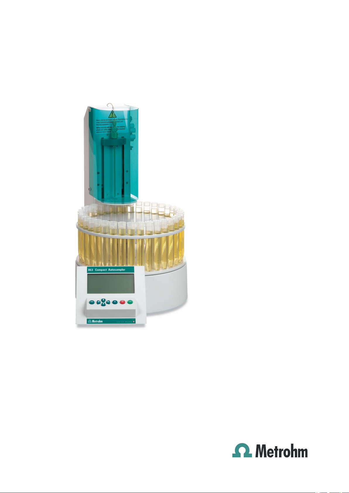
The 863 Compact Autosampler is an autosampler for ion chromatography
or voltammetry with a wide variety of applications. It can be used both as
a central control instrument in a stand-alone automation system or as an
integrated sample changer in a PC-controlled automation system.
1.1.1 Instrument versions
The 863 Compact Autosampler is available in two versions with different
accessories.
863 Compact IC Autosampler (2.863.0010)
With accessories for ion chromatography.
863 Compact VA Autosampler (2.863.0020)
With accessories for voltammetry.
1 Introduction
1.1.2 Instrument components
The 863 Compact Autosampler has the following components:
■ Turntable
Permanently mounted sample rack with 36 positions for sample tubes.
■ Lift with lift head
With needle holder for PEEK needles.
■ 1-channel peristaltic pump
For the transport of sample solutions.
■ USB (OTG) connector
For connection to a computer, to a printer or to a USB stick (for system
backup or method export).
■ Remote connector
For connecting instruments with a remote connector.
1.1.3 PC-controlled operation
If the 863 Compact Autosampler is controlled by means of a USB connection using the PC software MagIC Net, then arbitrary automation
sequences can be programmed. This allows optimal utilization of the
instrument components. The software can trigger the instrument components directly and use them more flexibly.
863 Compact Autosampler
■■■■■■■■
1
Page 12
1.2 About the documentation
1.1.4 Stand-alone operation
The 863 Compact Autosampler can be used as the central control instrument in an automation system which can include various ion chromatography instruments or the 797 VA Computrace. The 863 Compact Autosampler thereby plays the part of the reliable sample changer.
The given method sequences can be parameterized individually and saved
as sample-specific methods. Methods can be exported on an USB memory
stick and then copied onto another instrument quickly and easily.
1.1.5 Intended use
The 863 Compact Autosampler is designed for usage as an automation
system in analytical laboratories. It is not suitable for usage in biochemical, biological or medical environments in its basic equipment version.
1.2 About the documentation
Caution
■■■■■■■■■■■■■■■■■■■■■■
Please read through this documentation carefully before putting the
instrument into operation. The documentation contains information
and warnings which have to be followed by the user in order to ensure
safe operation of the instrument.
1.2.1 Symbols and conventions
The following symbols and styles are used in this documentation:
Method Dialog text, parameter in the software
File ▶ New
[Next] Button or key
Cross-reference to figure legend
The first number refers to the figure number, the
second to the instrument part in the figure.
Instruction step
Carry out these steps in the sequence shown.
Menu or menu item
Warning
■■■■■■■■
2
This symbol draws attention to a possible life hazard
or risk of injury.
863 Compact Autosampler
Page 13
■■■■■■■■■■■■■■■■■■■■■■
1 Introduction
Warning
This symbol draws attention to a possible hazard due
to electrical current.
Warning
This symbol draws attention to a possible hazard due
to heat or hot instrument parts.
Warning
This symbol draws attention to a possible biological
hazard.
Caution
This symbol draws attention to a possible damage of
instruments or instrument parts.
Note
This symbol marks additional information and tips.
1.3 Safety instructions
1.3.1 General notes on safety
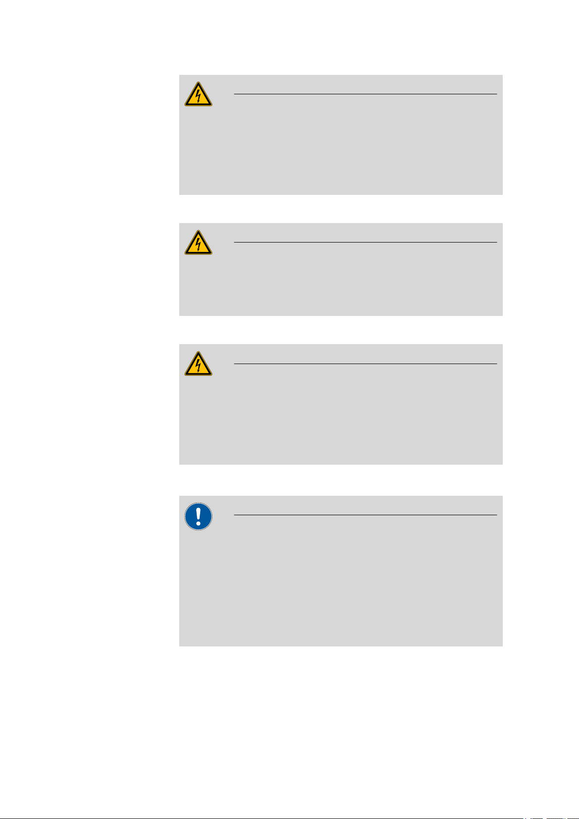
Warning
This instrument may only be operated in accordance with the specifications in this documentation.
This instrument has left the factory in a flawless state in terms of technical
safety. To maintain this state and ensure non-hazardous operation of the
instrument, the following instructions must be observed carefully.
1.3.2 Electrical safety
The electrical safety when working with the instrument is ensured as part
of the international standard IEC 61010.
Warning
Only personnel qualified by Metrohm are authorized to carry out service
work on electronic components.
863 Compact Autosampler
■■■■■■■■
3
Page 14
1.3 Safety instructions
■■■■■■■■■■■■■■■■■■■■■■
Warning
Never open the housing of the instrument. The instrument could be
damaged by this. There is also a risk of serious injury if live components
are touched.
There are no parts inside the housing which can be serviced or replaced
by the user.
Mains voltage
Warning
An incorrect mains voltage can damage the instrument.
Only operate this instrument with a mains voltage specified for it (see
rear panel of the instrument).
Protection against electrostatic charges
Warning
Electronic components are sensitive to electrostatic charges and can be
destroyed by discharges.
Always pull the mains cable out of the mains connection socket before
connecting or disconnecting electrical appliances on the rear panel of
the instrument.
1.3.3 Tubing and capillary connections
Caution
Leaks in tubing and capillary connections are a safety risk. Tighten all
connections well by hand. Avoid applying excessive force to tubing
connections. Damaged tubing ends lead to leakage. Appropriate tools
can be used to loosen connections.
Check the connections regularly for leakage. If the instrument is used
mainly in unattended operation, then weekly inspections are mandatory.
■■■■■■■■
4
863 Compact Autosampler
Page 15
■■■■■■■■■■■■■■■■■■■■■■
1.3.4 Personnel safety
Wear protective goggles and working clothes suitable for laboratory
work while operating the 863 Compact Autosampler. It is also advisable
to wear gloves when caustic liquids are used or in situations where
glass vessels could break.
Always install the safety shield supplied with the equipment before
using the instrument for the first time. Pre-installed safety shields are
not allowed to be removed.
The 863 Compact Autosampler may not be operated without a safety
shield!
1 Introduction
Warning
Warning
Warning
Personnel are not permitted to reach into the working area of the
instrument while operations are running!
A considerable risk of injury exists for the user.
Warning
In the event of a possible blockage of a drive, the mains plug must be
pulled out of the socket immediately. Do not attempt to free jammed
sample vessels or other parts while the device is switched on. Blockages
can only be cleared when the instrument is in a voltage-free status; this
action generally involves a considerable risk of injury.
Warning
The 863 Compact Autosampler is not suitable for utilization in biochemical, biological or medical environments in its basic equipment version.
863 Compact Autosampler
Appropriate protective measures must be implemented in the event
that potentially infectious samples or reagents are being processed.
■■■■■■■■
5
Page 16
1.3 Safety instructions
1.3.5 Flammable solvents and chemicals
Warning
All relevant safety measures are to be observed when working with
flammable solvents and chemicals.
■ Set up the instrument in a well-ventilated location.
■ Keep all sources of flame far from the workplace.
■ Clean up spilled fluids and solids immediately.
■ Follow the safety instructions of the chemical manufacturer.
1.3.6 Recycling and disposal
This product is covered by European Directive 2002/96/EC, WEEE – Waste
from Electrical and Electronic Equipment.
The correct disposal of your old equipment will help to prevent negative
effects on the environment and public health.
■■■■■■■■■■■■■■■■■■■■■■
More details about the disposal of your old equipment can be obtained
from your local authorities, from waste disposal companies or from your
local dealer.
■■■■■■■■
6
863 Compact Autosampler
Page 17
■■■■■■■■■■■■■■■■■■■■■■
1
2
3
4
5
6
2 Overview of the instrument
2 Overview of the instrument
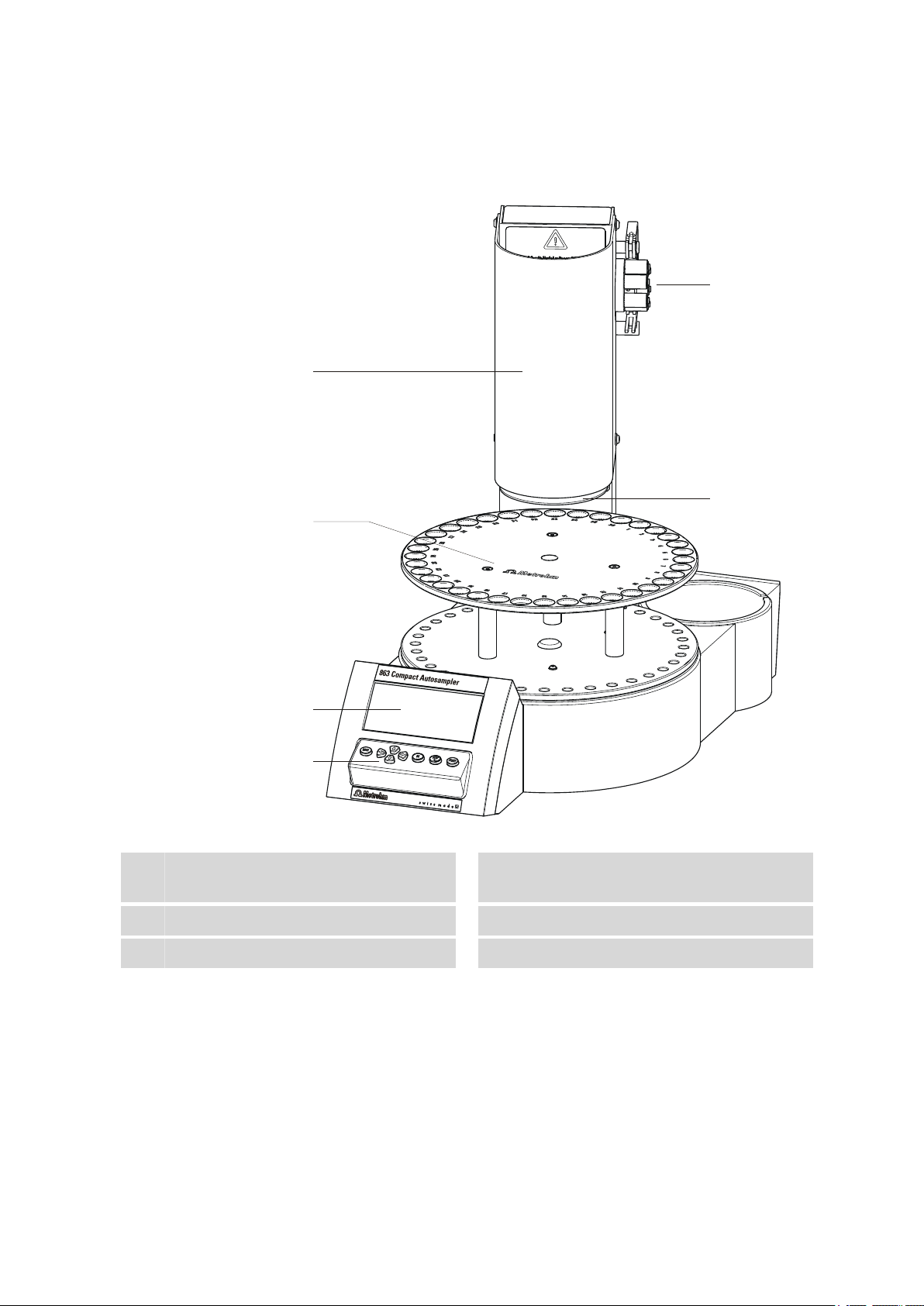
Figure 1 Front 863 Compact Autosampler
Safety shield
1
Display
3
Peristaltic pump
5
863 Compact Autosampler
Sample rack
2
For 36 sample tubes
Keypad
4
Retaining plate
6
■■■■■■■■
7
Page 18
■■■■■■■■■■■■■■■■■■■■■■
1
2
3 4 5 6
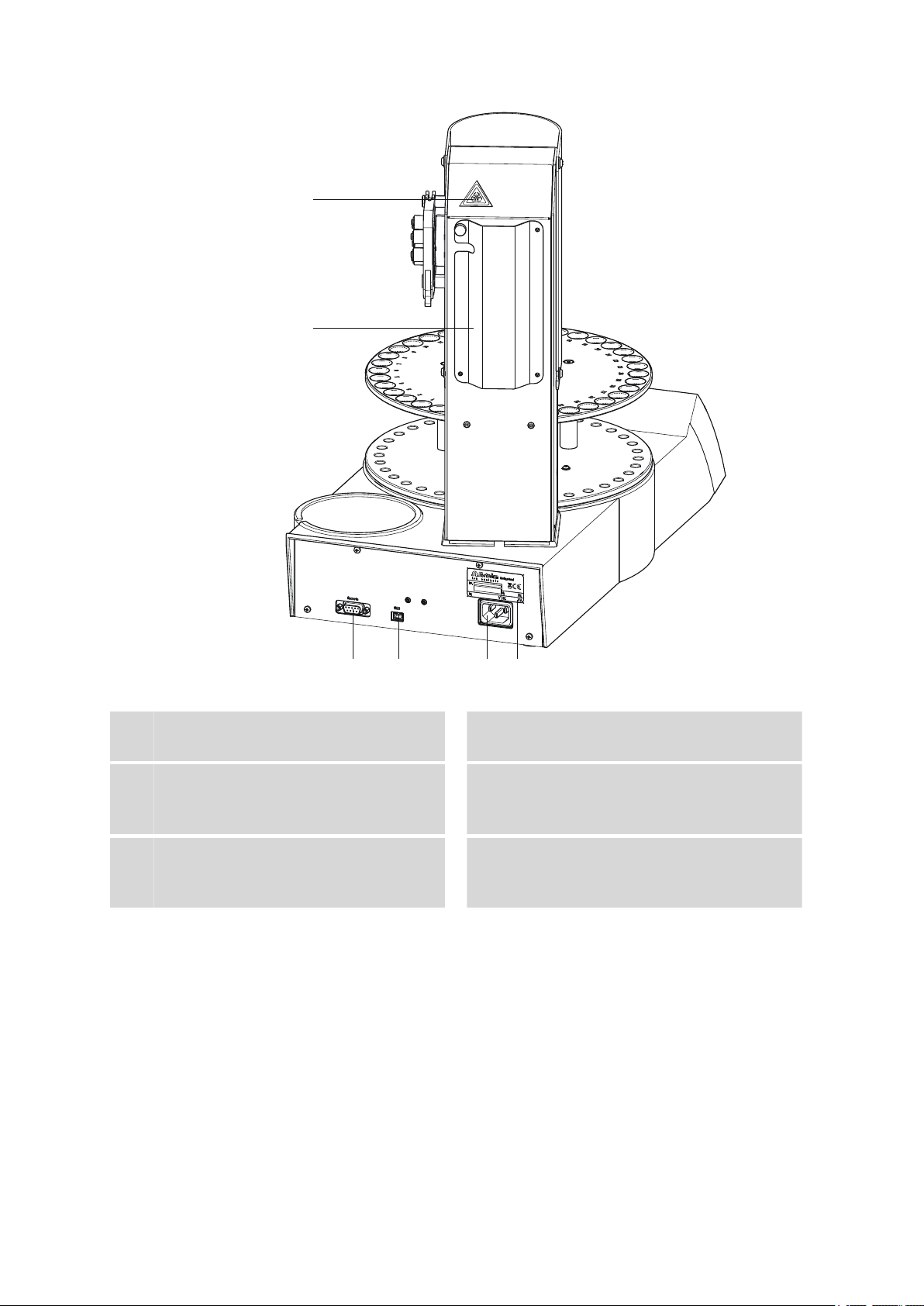
Figure 2 Rear 863 Compact Autosampler
Warning symbol
1
(see Chapter 1.3.4, page 5)
Remote connector
3
For connecting instruments with a remote
interface. D-Sub, 9-pin.
Mains connection socket
5
Tubing and cable cover
2
USB (OTG) connector
4
For connecting computers, printers, USB
sticks, USB hubs, etc.
Type plate
6
Contains specifications concerning mains
voltage and serial number.
■■■■■■■■
8
863 Compact Autosampler
Page 19
■■■■■■■■■■■■■■■■■■■■■■
1
2
3
4
5
2 Overview of the instrument
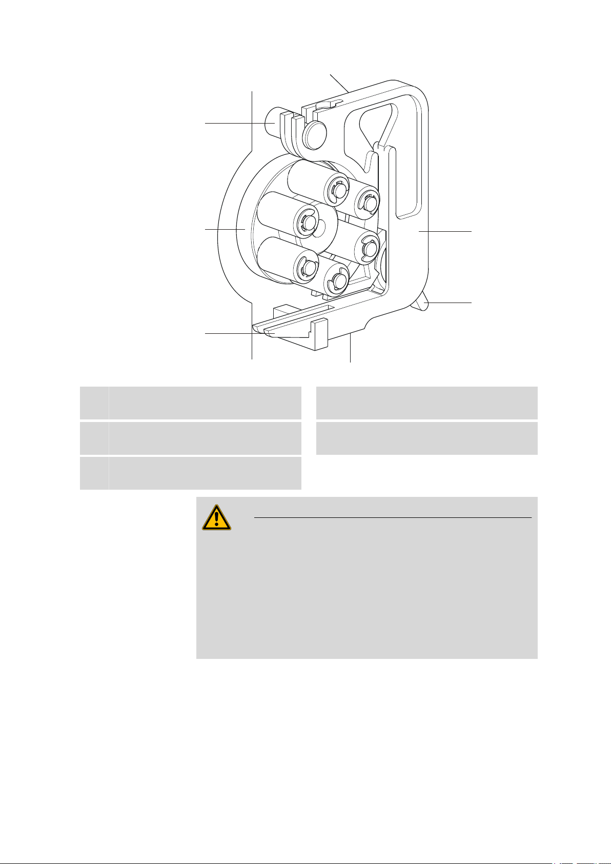
Figure 3 Peristaltic pump
Mounting pin
1
For engaging the tubing cartridge
Snap-action lever
3
For releasing the tubing cartridge
Contact pressure lever
5
For regulating contact pressure
Pump drive
2
Roller head with contact pressure rollers
Tubing cartridge 6.2755.000
4
For 6.1826.xx0 pump tubings
Warning
Never attempt to carry out manipulations on the tubing cartridge or on
the pump drive while the instrument is running. There is a considera-
ble risk of injury.
The pump tubing may not be replaced unless the instrument is
switched off.
Switch off the instrument immediately if the roller drive becomes
blocked. Only then should you attempt to eliminate the problem.
863 Compact Autosampler
■■■■■■■■
9
Page 20
3.1 Setting up the instrument
3 Installation
3.1 Setting up the instrument
3.1.1 Packaging
The instrument is supplied in highly protective special packaging together
with the separately packed accessories. Keep this packaging, as only this
ensures safe transportation of the instrument.
3.1.2 Checks
Immediately after receipt, check whether the shipment has arrived complete and without damage by comparing it with the delivery note.
3.1.3 Location
The instrument has been developed for operation indoors and may not be
used in explosive environments.
■■■■■■■■■■■■■■■■■■■■■■
Place the instrument in a location of the laboratory which is suitable for
operation, free of vibrations, protected from corrosive atmosphere, and
contamination by chemicals.
The instrument should be protected against excessive temperature fluctuations and direct sunlight.
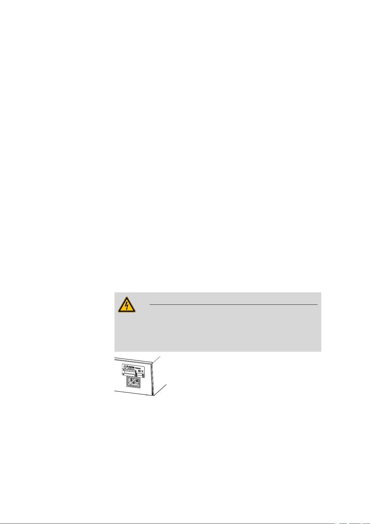
3.2 Connecting the mains cable
Warning
This instrument may only be used with the mains voltage specified (see
rear of the instrument).
Protect the connection sockets against moisture.
■■■■■■■■
10
Figure 4 Connecting the mains cable
863 Compact Autosampler
Page 21

■■■■■■■■■■■■■■■■■■■■■■
3.3 Connecting a computer
The 863 Compact Autosampler requires a USB connection to a computer
in order to be able to be controlled by the PC software MagIC Net (version 1.1 or newer). With a 6.2151.110 USB connection cable (Mini-USB
OTG/USB A), the instrument can be connected either directly to a USB
socket on a computer, to an attached USB hub or to another suitable
Metrohm instrument (e.g. 850 Professional IC, 881 Compact IC pro, 882
Compact IC plus or 883 Basic IC plus).
Note
If the 863 Compact Autosampler is not to be controlled by MagIC Net,
then no direct connection to a PC is required. In such cases, the instrument is used in so-called stand-alone mode and is connected via
remote cable to a corresponding control instrument.
3 Installation
Cable connection and driver installation
A driver installation is required in order to ensure that the 863 Compact
Autosampler is recognized by MagIC Net. To accomplish this, you must
comply with the procedures specified. The following steps are necessary:
1
Install the software
■ Insert the MagIC Net installation CD and carry out the installation
program directions.
■ Exit the program if you have started it after the installation.
2
Establish the cable connections
■ Connect the instrument to the mains supply if you have not
already done this.
■ Connect the instrument to a USB connector (Type A) of your com-
puter (see manual of your computer). The 6.2151.110 cable is
used for this purpose.
863 Compact Autosampler
■■■■■■■■
11
Page 22

3.3 Connecting a computer
6.2151.110
■■■■■■■■■■■■■■■■■■■■■■
Figure 5 Connecting the computer
The instrument is recognized. The now following driver installation
varies, depending on the version of the Windows operating system
used.
■ Either the required driver is installed automatically, or an installa-
tion assistant is started.
Follow the instructions of the installation assistant.
3
If problems should occur during installation, contact your company's IT
supporter.
Registering and configuring the instrument in MagIC Net
The instrument must be registered in the configuration of MagIC Net.
Once that has been done, you can then configure it according to your
requirements. Proceed as follows:
1
Set up the instrument
■ Start MagIC Net.
The instrument is automatically recognized. The configuration dialog for the instrument is displayed.
■ Make configuration settings for the instrument and its connec-
tors.
More detailed information concerning the configuration of the
instrument can be found in the documentation for the respective PC
software.
■■■■■■■■
12
863 Compact Autosampler
Page 23
■■■■■■■■■■■■■■■■■■■■■■
1
2
3
4
5
6
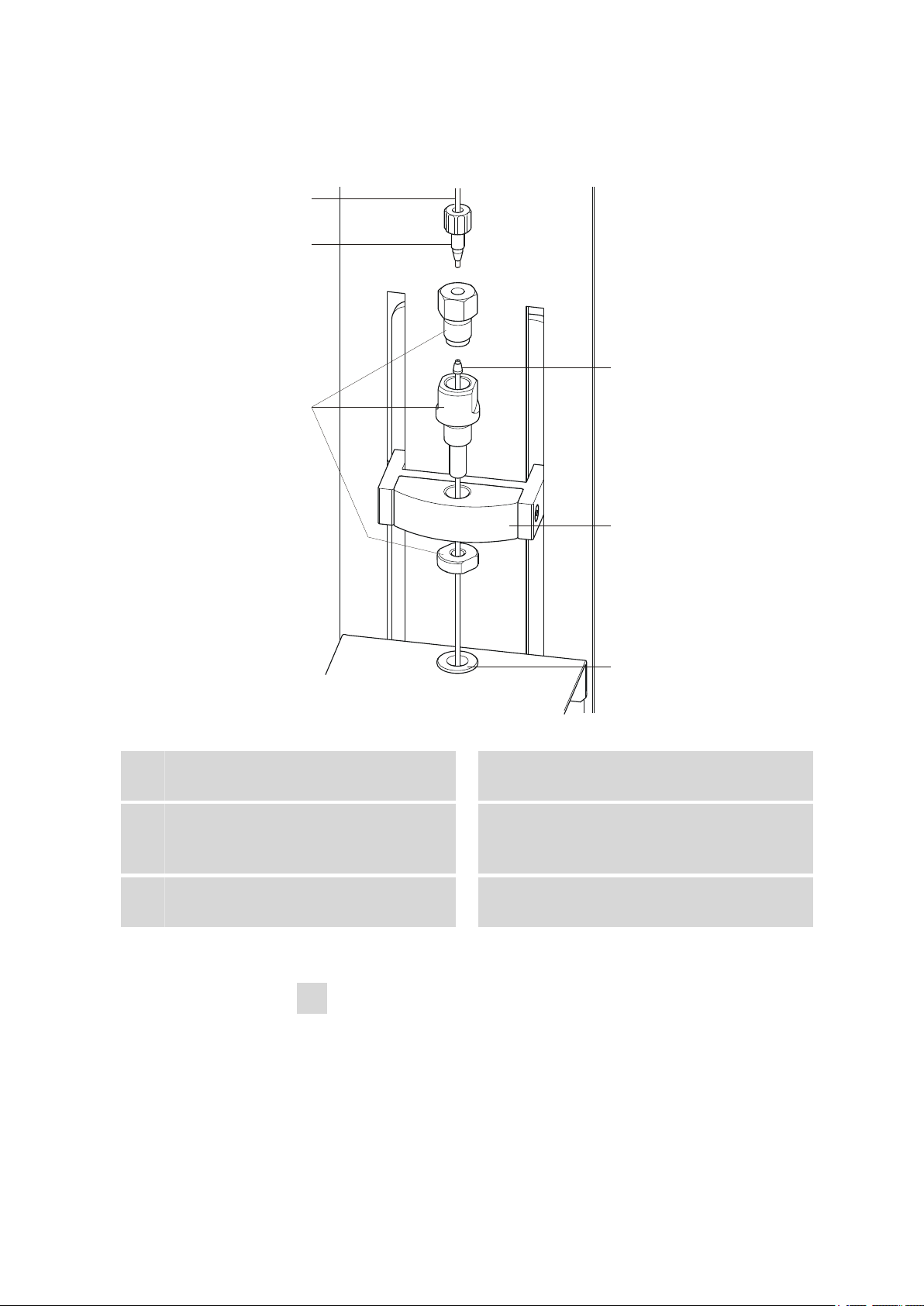
3.4 Setting up the needle holder
3 Installation
Figure 6 Installing the needle
PEEK capillary
1
6.1831.050 (40 cm) or 6.1831.060 (100 cm)
Needle holder (6.2833.030)
3
Comprising pressure screw, needle guide
and nut
Lift
5
With lift head
This is how you mount needle and capillary:
1
Open the safety shield
PEEK pressure screw (6.2744.070)
2
Sample aspiration needle (6.2846.000)
4
With PEEK ring wedge, outer diameter 1/8"
Centering aid
6
Loosen the lower two fastening screws of the safety shield using the
hexagon key provided, and tip up the safety shield.
863 Compact Autosampler
■■■■■■■■
13
Page 24

3.4 Setting up the needle holder
■■■■■■■■■■■■■■■■■■■■■■
2
Remove the nut
Loosen and remove the nut screwed onto the needle holder.
3
Insert the needle holder
Insert the needle holder in the lift head and screw it tight with the
nut from below.
4
Insert the needle
■ Loosen the pressure screw from the needle holder and remove it.
■ Insert the needle part way from above into the opening of the
needle holder.
■ Slide the PEEK ring wedge down over the needle from above. The
narrow side of the seal must face upwards.
5
Fasten the needle
■ Screw the pressure screw into the needle holder from above. At
the same time push the needle slightly upward from below to
apply a little pressure.
■ Tighten the pressure screw firmly.
6
Connect the capillary
■ Slide a 6.2744.010 PEEK pressure screw over the end of the capil-
lary.
■ Manually screw tight the PEEK pressure screw with the capillary in
the pressure screw resting on the needle holder. The capillary
must be pressed tight while doing so.
7
Close the safety shield
Tip down the safety shield and fix it with the fastening screws.
■■■■■■■■
14
Warning
The safety shield must always be closed for safety reasons during operation of the 863 Compact Autosampler.
863 Compact Autosampler
Page 25
■■■■■■■■■■■■■■■■■■■■■■
1 2 3 4 5 6 7 8 1
9 10 3
6.2744.160
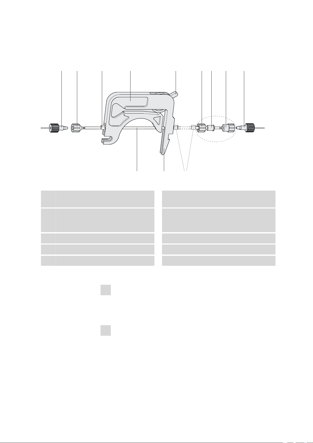
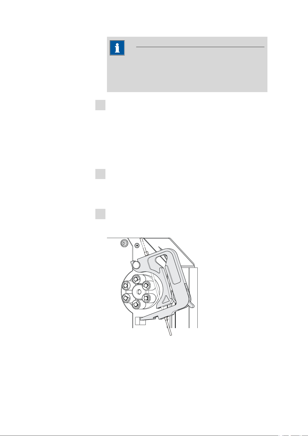
3.5 Installing the peristaltic pump
3 Installation
Figure 7 Installing the pump tubing
PEEK pressure screws, short
1
(6.2744.070)
Stopper
3
The colors of the stopper indicate the inner
diameter of the pump tubing.
Contact pressure lever
5
Adapter
7
Pump tubing (6.1826.xx0)
9
Tubing olive (6.2744.034)
2
Tubing cartridge (6.2755.000)
4
Union nut
6
Tubing olive
8
Snap-action lever
10
Mount the pump tubing as follows:
1
Removing the tubing cartridge
Release the tubing cartridge from the cartridge holder by pressing
the snap-action lever and unhooking from the mounting pins (see
Figure 3, page 9).
2
Connecting the aspiration side
863 Compact Autosampler
Place a 6.2744.034 tubing olive (7-2) on the aspiration side of the
pump tubing.
■■■■■■■■
15
Page 26
3.5 Installing the peristaltic pump
■■■■■■■■■■■■■■■■■■■■■■
Note
For the voltammetry, we recommend connecting the aspiration
side the same way as the pressure side, see following section. The
necessary second set of the 6.2744.160 pump tubing connection
is enclosed.
3
Connecting the pressure side
■ Slide the union nut (7-6) of the 6.2744.160 pump tubing connec-
tion (without filter) onto the pump tubing.
■ Select a suitable adapter (7-7) and slide it onto the pump tubing.
The type of adapter depends on the pump tubing (see Table 1,
page 17).
■ Place the tubing olive (7-8) onto the pump tubing.
■ Screw the union nut (7-6) tight on the tubing olive (7-8).
4
Inserting the pump tubing
■ Press the contact pressure lever all the way down.
■ Place the pump tubing in the tubing cartridge. The stoppers (7-3)
must snap into the corresponding holders of the tubing cartridge.
5
Inserting the tubing cartridge
■ Hang the tubing cartridge in the mounting pin and press in the
cartridge holder until the snap-action lever snaps in.
■■■■■■■■
16
Figure 8 Inserting the tubing cartridge
863 Compact Autosampler
Page 27

■■■■■■■■■■■■■■■■■■■■■■
6
Connecting the capillaries
■ Screw the respective capillaries tightly to the two tubing olives
with PEEK pressure screws (7-1).
Table 1 Pump tubings and suitable adapters
Pump tubing Adapter
6.1826.020 (blue/blue)
6.1826.310 (orange/green)
6.1826.320 (orange/yellow)
6.1826.330 (orange/white)
6.1826.340 (black/black)
3 Installation
6.1826.360 (white/white)
6.1826.380 (gray/gray)
6.1826.390 (yellow/yellow)
Set flow rate
The contact pressure of the tubing cartridge must be adjusted in order to
regulate the flow rate. Proceed as follows:
Set the contact pressure
■ Fully loosen the contact pressure lever (7-5), i.e. press it all the
1
way down.
■ Switch on the peristaltic pump.
■ Raise the contact pressure lever one step at a time until liquid
flows.
■ When liquid starts flowing, raise the contact pressure lever by an
additional 2 ratchet increments.
863 Compact Autosampler
The contact pressure is now set optimally.
The delivery rate depends not only on the correct contact pressure
but also on the interior diameter of the pump tubing and the rotational speed of the drive.
■■■■■■■■
17
Page 28
3.6 Tubing and capillary connections
Inject
Note
Pump tubings are consumable material. The service life of the pump
tubings depends on the contact pressure amongst other factors.
3.6 Tubing and capillary connections
■■■■■■■■■■■■■■■■■■■■■■
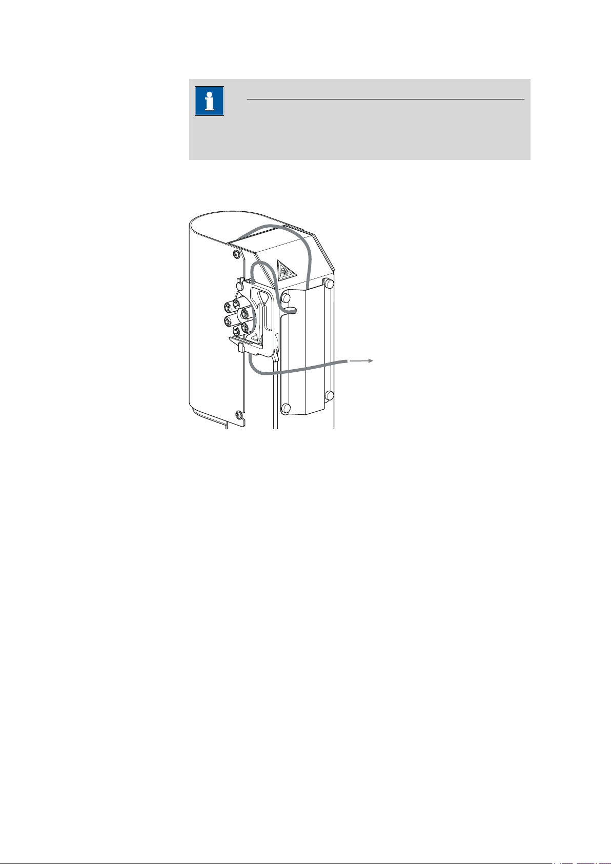
Figure 9 Tubing guide
In order to lay the tubing and capillaries neatly, you can insert them into
the tubing cover on the rear side of the tower. The above illustration
shows one of the possible variants. The tubing cover can be removed by
loosening the four red knurled screws.
3.7 Connecting a keyboard, printer and other USB devices
The 863 Compact Autosampler has a USB (OTG) connector. Use the provided 6.2151.100 adapter USB MINI (OTG) - USB A for connecting USB
devices as e.g. printers, keyboards or USB sticks, see the following figure.
■■■■■■■■
18
863 Compact Autosampler
Page 29
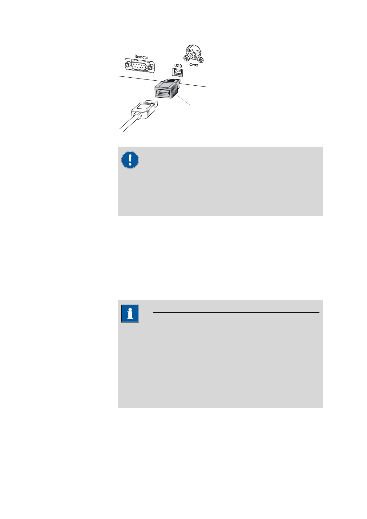
■■■■■■■■■■■■■■■■■■■■■■
6.2151.100
3 Installation
Figure 10 Connecting USB devices
Caution
Switch the instrument off before connecting or disconnecting a USB
device or a USB stick.
The 863 Compact Autosampler can only recognize the device immediately after switching on.
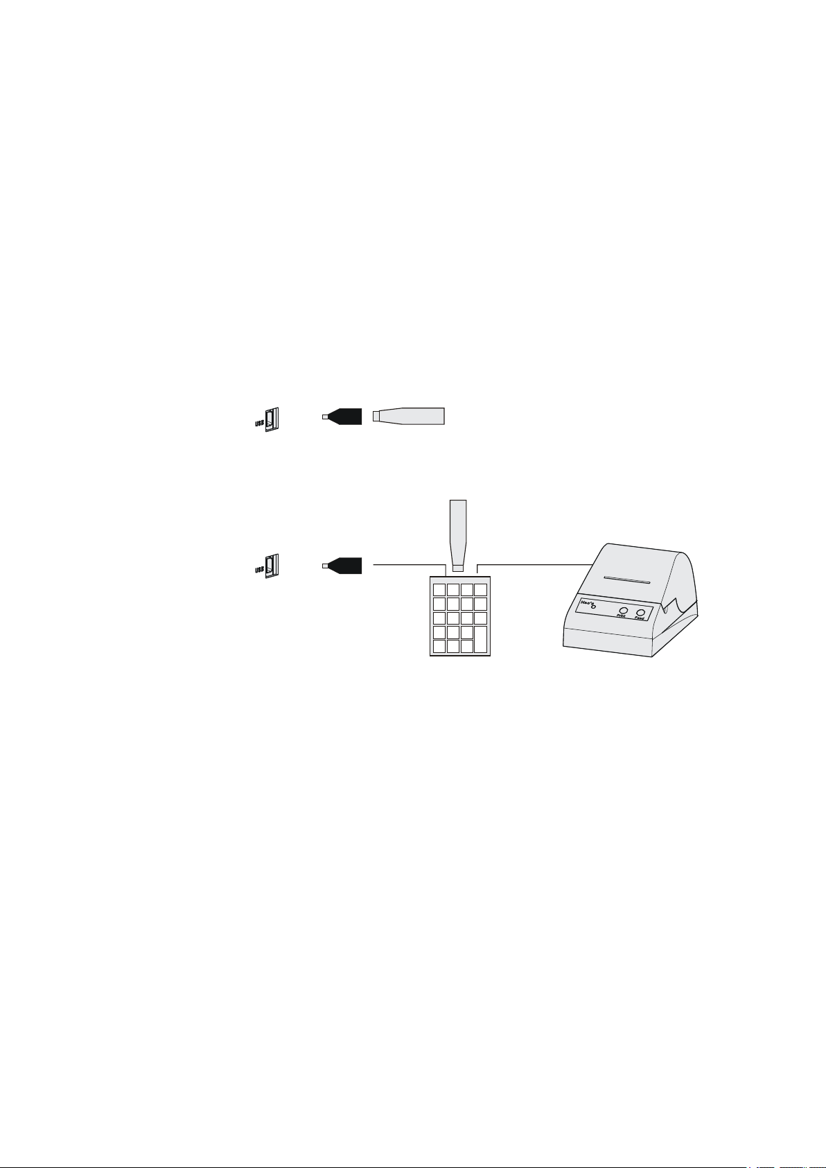
The following devices can be operated directly on the USB connector
with the 6.2151.100 adapter:
■ USB sticks (for the backup or storing of methods)
■ 6.2147.000 numerical USB keypad
■ USB hub (with or without an own power supply)
The 6.2147.000 numerical USB keypad serves for comfortable numerical input and for navigating in the dialog. In addition, it provides two USB
connectors. Connect additional USB devices to the keypad.
Note
Most of the USB devices need a so-called hub in order to work correctly.
A USB hub is a distributor to which several USB devices can be connected. USB hubs are available in specialty stores in a number of different
models.
The USB (OTG) connector of the 863 Compact Autosampler has no
such hub. The 6.2147.000 numerical USB keypad has a USB hub and
two USB connectors.
863 Compact Autosampler
The following devices can only be connected to a 6.2147.000
numerical keypad or to a USB hub:
■ Printer (with USB connector, use the 6.2151.020 connecting cable)
■■■■■■■■
19
Page 30
3.7 Connecting a keyboard, printer and other USB devices
USB MINI (OTG)-USB
USB stick
6.2151.100
USB MINI (OTG)-USB
USB stick
Keypad
6.2147.000
6.2151.100
Printer
■ Barcode reader (with USB cable)
■ Mouse (PC mouse with USB cable, for navigating in the dialog)
The following devices can only be connected to a USB hub:
■ PC keyboard (with USB cable, for the comfortable input of letters and
numbers)
■ Keypad with numerical keypad (with USB cable)
If you wish to connect several different instruments without own
power supply, then you must possibly use a USB hub with own power
supply (self powered). The USB (OTG) connector of the 863 Compact
Autosampler is not designed for supplying power to several devices with
elevated electricity requirements.
Examples:
Figure 11 Connecting the USB stick
■■■■■■■■■■■■■■■■■■■■■■
■■■■■■■■
20
Figure 12 Connecting the 6.2147.000 USB keyboard with USB stick and
printer
863 Compact Autosampler
Page 31

■■■■■■■■■■■■■■■■■■■■■■
6.2141.270
S
WARNING - Fire Hazard -
with the same type and rating of fuse
For continued protection replace only
Type 1.761.
Fuse
100-120V:
220-240V:
1,0A(T)
0,5A(T)
Made by Metrohm Herisau Switzerland
RS 232
Detector Block
Remote
Waste B
Waste A
Transport security screws
861 Compact IC
863 Compact Autosampler
3.8 Remote connections
The 863 Compact Autosampler can be used as a control device for a simple automation system with a large variety of different instruments. Even
older Metrohm instruments can thus be integrated into an automated
analysis system.
3.8.1 Connecting IC instruments
The following illustration shows, as an example, the connection of an 861
Compact IC. In addition, the following IC instruments can be connected
with the 6.2141.270 remote cable: 732 IC Detector, 761 Compact IC, 790
Personal IC, 819 IC Detector und 844 UV/VIS Compact IC.
3 Installation
3.8.2 Connecting a 797 VA Computrace
Figure 13 Remote connection 863 Compact Autosampler - 861 Com-
An 843 Pump Station is also required for operation with a 797 VA Computrace.
pact IC
863 Compact Autosampler
■■■■■■■■
21
Page 32

3.8 Remote connections
6.2141.230
6.2141.280
843 Pump Station
863 Compact Autosampler
797 VA Computrace
■■■■■■■■■■■■■■■■■■■■■■
Figure 14 Remote connection 863 Compact Autosampler - 843 Pump
Station - 797 VA Computrace
The 863 Compact Autosampler is connected with a 6.2141.230 cable to
the Remote 2 connector of the 843 Pump Station. Remote 1 is connected to the 797 VA Computrace with the aid of a 6.2141.280 cable.
The pumps of the 843 Pump Station are activated by the 797 VA Computrace.
■■■■■■■■
22
863 Compact Autosampler
Page 33

■■■■■■■■■■■■■■■■■■■■■■
4 Automation sequences
Note
The following method sequences and parameters can only be used if
the 863 Compact Autosampler is not controlled by a PC software (e.g.
MagIC Net) via USB connection.
4.1 Sample with air gap
This method template is suitable for simple determinations.
An air gap is formed in the transfer tubing between the individual samples.
4 Automation sequences
Preparing and starting the sample series
Press [START].
1
Under Number of samples, enter the number of samples or the
2
maximum value of 99.
Under Next sample pos., enter the rack position of the first sample
3
to be processed.
Press [BACK].
4
Start the sample series in the IC Net software.
5
Note
The method run will be automatically restarted for every sample via
remote connection (Autostart). A stepping pulse of the connected
instrument is expected at the end of the method run. The 863 Compact
Autosampler must be stopped manually by means of the button
[STOP] after the processing of the last sample.
863 Compact Autosampler
The individual steps of the method:
■ Move to the sample
■■■■■■■■
23
Page 34

4.2 Sample no air gap
■ Lower the lift to the work position
■ Switch on the peristaltic pump for the sample transfer
■ Wait for the pump time to be completed
■ Switch off the peristaltic pump
■ Move the lift upward
■ Switch on the peristaltic pump
■ Wait for the waiting time for air gap to be completed
■ Switch off the peristaltic pump
■ Wait for the stepping pulse
4.2 Sample no air gap
This method template is suitable for simple determinations.
No air gap is formed in the transfer tubing between the individual samples.
Preparing and starting the sample series
Press [START].
1
Under Number of samples, enter the number of samples or the
2
maximum value of 99.
Under Next sample pos., enter the rack position of the first sample
3
to be processed.
Press [BACK].
4
Start the sample series in the IC Net software.
5
■■■■■■■■■■■■■■■■■■■■■■
■■■■■■■■
24
Note
The method run will be automatically restarted for every sample via
remote connection (Autostart). A stepping pulse of the connected
instrument is expected at the end of the method run. The 863 Compact
Autosampler must be stopped manually by means of the button
[STOP] after the processing of the last sample.
The individual steps of the method:
■ Move to the sample
■ Lower the lift to the work position
■ Switch on the peristaltic pump for the sample transfer
863 Compact Autosampler
Page 35

■■■■■■■■■■■■■■■■■■■■■■
■ Wait for the pump time to be completed
■ Switch off the peristaltic pump
■ Wait for the stepping pulse
4.3 Double injection
This method template enables two sample transfers of the same sample.
No air gap is formed in the transfer tubing between the individual samples.
Preparing and starting the sample series
Press [START].
1
Under Number of samples, enter the number of samples or the
2
maximum value of 99.
Under Next sample pos., enter the rack position of the first sample
3
to be processed.
Press [BACK].
4
Start the sample series in the IC Net software.
5
4 Automation sequences
Note
The method run will be automatically restarted for every sample via
remote connection (Autostart). A stepping pulse of the connected
instrument is expected at the end of the method run. The 863 Compact
Autosampler must be stopped manually by means of the button
[STOP] after the processing of the last sample.
The individual steps of the method:
■ Move to the sample
■ Lower the lift to the work position
■ Switch on the peristaltic pump for the first sample transfer
■ Wait for the pump time to be completed
■ Switch off the peristaltic pump
■ Wait for the stepping pulse
■ Switch on the peristaltic pump for the second sample transfer
■ Wait for the pump time to be completed
■ Switch off the peristaltic pump
863 Compact Autosampler
■■■■■■■■
25
Page 36

4.4 Triple injection
■ Wait for the stepping pulse
4.4 Triple injection
This method template enables three sample transfers of the same sample.
No air gap is formed in the transfer tubing between the individual samples.
Preparing and starting the sample series
Press [START].
1
Under Number of samples, enter the number of samples or the
2
maximum value of 99.
Under Next sample pos., enter the rack position of the first sample
3
to be processed.
Press [BACK].
4
Start the sample series in the IC Net software.
5
■■■■■■■■■■■■■■■■■■■■■■
Note
The method run will be automatically restarted for every sample via
remote connection (Autostart). A stepping pulse of the connected
instrument is expected at the end of the method run. The 863 Compact
Autosampler must be stopped manually by means of the button
[STOP] after the processing of the last sample.
The individual steps of the method:
■ Move to the sample
■ Lower the lift to the work position
■ Switch on the peristaltic pump for the first sample transfer
■ Wait for the pump time to be completed
■ Switch off the peristaltic pump
■ Wait for the stepping pulse
■ Switch on the peristaltic pump for the second sample transfer
■ Wait for the pump time to be completed
■ Switch off the peristaltic pump
■ Wait for the stepping pulse
■ Switch on the peristaltic pump for the third sample transfer
■■■■■■■■
26
863 Compact Autosampler
Page 37

■■■■■■■■■■■■■■■■■■■■■■
■ Wait for the pump time to be completed
■ Switch off the peristaltic pump
■ Wait for the stepping pulse
4.5 VA 797 Remote start
This method template is suitable for sample transfer to a 797 VA Computrace. The actual pump time is determined by the control software.
The sample series is started on the 797 VA Computrace (Remote Start).
Preparing and starting the sample series
Press [START].
1
Under Number of samples, enter the number of samples or the
2
maximum value of 99.
Under Next sample pos., enter the rack position of the first sample
3
to be processed.
Press [BACK].
4
Start the sample series in the VA Computrace software.
5
4 Automation sequences
Note
The method run will be automatically restarted for every sample via
remote connection (Autostart). A stepping pulse of the connected
instrument is expected at the end of the method run. The 863 Compact
Autosampler must be stopped manually by means of the button
[STOP] after the processing of the last sample.
The individual steps of the method:
■ Move to the sample
■ Lower the lift to the work position
■ Wait for the stepping pulse
■ Switch on the peristaltic pump for the sample transfer
■ Wait for the minimum pump time to be completed
■ Wait for the stepping pulse
■ Switch off the peristaltic pump
■ 2 seconds waiting time
■ Wait for the stepping pulse
863 Compact Autosampler
■■■■■■■■
27
Page 38

4.6 VA 797 Manual start
4.6 VA 797 Manual start
This method template is suitable for sample transfer to a 797 VA Computrace. The actual pump time is determined by the control software.
Preparing and starting the sample series
Press [START].
1
Under Number of samples, enter the number of samples or the
2
maximum value of 99.
Under Next sample pos., enter the rack position of the first sample
3
to be processed.
Press [START].
4
■■■■■■■■■■■■■■■■■■■■■■
Note
The method run will be automatically restarted for every sample via
remote connection (Autostart). A stepping pulse of the connected
instrument is expected at the beginning of the method run. The 863
Compact Autosampler may need to be stopped manually by means of
the button [STOP] after the processing of the last sample.
The individual steps of the method:
■ Wait for the stepping pulse
■ Move to the sample
■ Lower the lift to the work position
■ Wait for the stepping pulse
■ Switch on the peristaltic pump for the sample transfer
■ Wait for the minimum pump time to be completed
■ Wait for the stepping pulse
■ Switch off the peristaltic pump
■■■■■■■■
28
863 Compact Autosampler
Page 39

■■■■■■■■■■■■■■■■■■■■■■
5 Operation
5.1 Switching the instrument on and off
Switching on the instrument
Proceed as follows:
■ Press the red [STOP] key.
1
The instrument is initialized and a system test performed. This
process takes some time.
The main dialog is displayed:
5 Operation
Switching off the instrument
The instrument is switched off with the [STOP] key. The fact that the key
needs to be pressed down for an extended time prevents accidental
switch off.
Proceed as follows:
■ Keep the red [STOP] key pressed down for at least 3 s.
1
A progress bar is displayed. If the key is released during this time,
then the instrument will not be switched off.
863 Compact Autosampler
■■■■■■■■
29
Page 40

5.2 Fundamentals of operation
5.2 Fundamentals of operation
5.2.1 The keypad
Figure 15 Keypad 863 Compact Autosampler
BACK Apply the input and exit the dialog.
⇧ ⇩ Move the selection bar either up or down by one
line at a time. Select the character to be entered
in the text editor.
⇦ ⇨ Select the character to be entered in the text and
number editor. Select the individual functions in
the function bar.
■■■■■■■■■■■■■■■■■■■■■■
OK Confirm the selection.
STOP Stop an ongoing method run or a manual func-
tion. Switch the instrument on/off.
START Start a method run.
5.2.2 Structure of the dialog windows
The current dialog title is displayed on the left-hand side of the title line.
The current status of the system is displayed in the upper right-hand corner:
ready The instrument is in normal status.
busy A method has been started.
hold A method has been paused.
■■■■■■■■
30
Some dialogs have a so-called function bar on the bottom line. The functions contained therein can be selected with the arrow keys [⇦] or [⇨]
and executed with [OK].
863 Compact Autosampler
Page 41

■■■■■■■■■■■■■■■■■■■■■■
5.2.3 Navigating in the dialog
The selection bar is displayed in inverted style. Use the arrow keys [⇧] and
[⇩] to move the selection bar upward or downward one line at a time. If
a dialog text is marked with ">", then additional settings are available in
a subordinate dialog. Use [OK] to access this dialog.
Example: System settings
5 Operation
Use the [BACK] key to return to the next higher level.
5.2.4 Entering text and numbers
In the editing dialog for text or numerical input you can select the individual characters with the arrow keys. Use [OK] to apply the character in the
input field. The following functions are available:
Editing function Description
Accept
Cancel
Clear
The modification is applied and the editing dialog
is exited.
The editing dialog is exited without applying the
modification.
The content of the input field is deleted completely.
863 Compact Autosampler
■■■■■■■■
31
Page 42

5.3 Methods
■■■■■■■■■■■■■■■■■■■■■■
Editing function Description
The character left of the cursor is deleted (backspace).
Text editor only
The cursor within the input field is shifted to the
left by one character each time that [OK] is
pressed.
Text editor only
The cursor within the input field is shifted to the
right by one character each time that [OK] is
pressed.
[BACK]
The [BACK] key has the same function as Accept.
5.3 Methods
The 863 Compact Autosampler works with process methods that are
based on specified method templates. Individual working steps of a
method run can be individually parameterized, depending on the application. An optimized method run can be saved as a reusable method.
5.3.1 Method templates
The 863 Compact Autosampler contains method templates which are
already configured except for a few parameters.
The following method templates can be selected:
Sample with air
gap
Sample no air gap Sample transfer for IC without air gap between
The modification is applied and the editing dialog
is exited.
Sample transfer for IC with air gap between the
samples.
the samples.
■■■■■■■■
32
Double injection Two-time sample transfer for IC without air gap
between the transfers.
Triple injection Three-time sample transfer for IC without air gap
between the transfers.
VA 797 Remote
start
VA 797 Manual
start
Sample transfer for VA applications with remote
start of the 863 Compact Autosampler by the
797 Computrace.
Sample transfer for VA applications with manual
start of the 863 Compact Autosampler.
863 Compact Autosampler
Page 43

■■■■■■■■■■■■■■■■■■■■■■
You will find a detailed description of the methods in chapter 4 Automation sequences, page 23ff.
5.3.2 Creating a new method
Proceed as follows to create a new method:
1
Open the method table
■ In the main dialog, select Method and press [OK].
The method table opens:
2
Select the method template
■ In the function bar, select New and press [OK].
5 Operation
The list of method templates opens:
3
Load the method template
■ Select the desired template and press [OK].
The method template is now loaded and is displayed in the main dialog under Method.
If a new method has been created, then the individual parameters can be
modified under Menu ▶ Parameters.
5.3.3 Saving a method
If you modify method parameters, then you can save these as your own
method. A maximum of 100 methods can be saved.
863 Compact Autosampler
■■■■■■■■
33
Page 44

5.3 Methods
To save a method, proceed as follows:
1
Open the method table
■ In the main dialog, select Method and press [OK].
The method table opens:
2
Modify/apply the method name
■ In the function bar, select Store and press [OK].
A method name will be suggested for new methods. If the
method has already been saved once, then the method name will
be displayed:
■■■■■■■■■■■■■■■■■■■■■■
Apply the name:
■ Press [BACK].
The method will be saved and the method table is displayed.
Enter a new name:
■ Press [OK].
The text editor opens.
■ Enter a method name (max. 12 characters) and apply with
Accept or [BACK].
■ Press [BACK].
The method will be saved and the method table is displayed.
■■■■■■■■
34
863 Compact Autosampler
Page 45

■■■■■■■■■■■■■■■■■■■■■■
5.3.4 Loading a method
To load a method, proceed as follows:
1
Open the method table
■ In the main dialog, select Method and press [OK].
The method table with the stored methods opens:
2
Select a method
■ Select the desired method.
3
Load the method
■ In the function bar, select Load and press [OK].
5 Operation
The method is now loaded and is displayed in the main dialog under
Method.
5.3.5 Exporting a method
The methods can be exported on a connected USB stick.
This function is possible only if a USB stick is connected as an external
storage medium.
To export a method, proceed as follows:
1
Open the method table
■ In the main dialog, select Method and press [OK].
The method table with the stored methods opens:
Note
863 Compact Autosampler
■■■■■■■■
35
Page 46

5.4 Performing a sample series
2
Select a method
■ Select the desired method.
3
Export the method
■ In the function bar, select Export and press [OK].
The method is being exported. The directory structure on the USB
stick is listed in chapter 6.2, page 47.
5.4 Performing a sample series
■■■■■■■■■■■■■■■■■■■■■■
Samples can be placed anywhere on the rack. They are processed according to ascending rack position.
If the 863 Compact Autosampler is used together with the 797 Computrace, each vessel with sample has to be followed by one with ultrapure
water.
Note
The following descriptions are only of significance if the 863 Compact
Autosampler is operated in stand-alone operation, i.e. not controlled by
a PC via a USB connection.
5.4.1 Starting the sample series
Starting a sample series
A suitable method must be loaded before a sample series is started (see
Chapter 5.3.4, page 35). The necessary parameters ) can then be modi-
fied.
1
Define the sample series
Press the [START] key.
■■■■■■■■
36
863 Compact Autosampler
Page 47

■■■■■■■■■■■■■■■■■■■■■■
You can now enter the quantity and the first rack position of the
samples to be processed.
2
Enter the number of samples
■ Select Number of samples and press [OK].
■ Enter the number of samples. If the methods to be started via
remote connection are used, the maximum value for the number
of samples (99) can be entered here.
■ Close the input dialog with [BACK] or Accept.
3
Enter the rack position of the first sample
■ Select Next sample pos. and press [OK].
■ Enter the starting position of the sample series.
■ Close the input dialog with [BACK] or Accept.
5 Operation
The value for the number of samples remains saved for the next sample series. The position of the first sample is increased with each
method run.
You can still cancel the start of the sample series at this time with
[BACK] or [STOP].
4
Close the sample series dialog
Close the dialog with the [BACK] key.
5
Start the sample series
Start the sample series in the PC software (IC-Net or VA Computrace).
The sample changer is started automatically by the remote connection.
863 Compact Autosampler
■■■■■■■■
37
Page 48

5.4 Performing a sample series
Note
When using the method template VA 797 Manual start, the
method has to be started first at the sample changer in the sample
series dialog with the [START] key. The sample changer then
waits for a stepping pulse of the 797 VA Computrace.
Stopping a sample series
A sample series can be canceled at any time.
Press the [STOP] key.
1
The method run is stopped. The sample series cannot be resumed.
5.4.2 Pausing a sample series and continuing
■■■■■■■■■■■■■■■■■■■■■■
Pausing a sample series
A method run of the 863 Compact Autosampler can be paused and then
continued again. The connected instruments are however not paused.
Note
Interruption of the method run is not possible during the execution of
commands during which the 863 Compact Autosampler waits for a signal from the connected titrator. This is the case during the conditioning
of the titration cell and the execution of the KF titration.
No interruption is possible while the 863 Compact Autosampler waits for
a remote signal.
■■■■■■■■
38
A function bar with the entry "Hold" is displayed during the run of a sample series in the so-called "Live" dialog.
Press the [OK] key.
1
863 Compact Autosampler
Page 49

■■■■■■■■■■■■■■■■■■■■■■
5 Operation
The method run is paused. However, currently running movements
of the sample rack or the lift will be finished.
Instead of the "Hold" function, "Continue" is displayed in the function bar.
Continuing sample series
If a method run is paused, then the "Hold" status is displayed in the title
bar, see previous figure. The sequence can be continued with the "Con-
tinue" function.
In the "Hold" status, a method run can be stopped completely, and with
it the entire sample series, by pressing the [STOP] key.
Press the [OK] key.
1
As is also the case at the start of a sample series, a request dialog
appears here in which the number of samples to be processed can
still be changed. It is thus possible to shorten a sample series or to
extend it, without stopping it.
Press the [OK] key and enter the number of samples that still need to
2
be processed. The current sample must be taken into account.
Press the [START] key.
3
The sample series continues.
863 Compact Autosampler
■■■■■■■■
39
Page 50

5.5 Printing a report manually
5.5 Printing a report manually
Menu ▶ Print reports
To print a report manually, proceed as follows:
1
Open the main menu
■ In the main dialog, select Menu and press [OK].
2
Open the print dialog
■ Select the menu item Print reports and press [OK].
■■■■■■■■■■■■■■■■■■■■■■
The dialog window with the available reports opens:
3
Select a report
■ Select the desired report and press [OK].
The report is being printed out.
The following reports can be printed out manually:
Parameters Report with all method parameters of the loaded
method.
System System report with system settings, solution list,
external devices, etc.
■■■■■■■■
40
863 Compact Autosampler
Page 51

■■■■■■■■■■■■■■■■■■■■■■
5.6 Manual control
The manual control of sample rack, lift and peristaltic pump is accomplished directly in the main dialog. If one of the lines Rack position, Lift
position or Pump is selected, then a function bar will appear at the lowest line with the selection of available functions.
5.6.1 Rotating the sample rack
If the Rack position line is selected, then the arrow keys [⇨] and [⇦] can
be used to select one of the following functions, which can then be run
by pressing [OK]:
5 Operation
Next The lift is moved upward and the next-higher
rack position is placed in front of the lift.
If the [OK] key remains pressed, the rack automatically moves to the next position.
Previous The lift is moved upward and the next-lower
rack position is placed in front of the lift.
If the [OK] key remains pressed, the rack automatically moves to the next position.
Reset The rack is initialized. The lift is moved upward
and the sample rack is rotated to the starting
position. At the same time, the starting position
(Next sample pos.) is reset to 1 for the start of
the next sample series.
The rack position display is always updated as soon as the rack is in the
new position.
863 Compact Autosampler
■■■■■■■■
41
Page 52

5.6 Manual control
5.6.2 Moving the lift
If the Lift position line is selected, then the lift can be moved to the position suggested in the function bar by pressing [OK]. Only two positions
are possible:
Work pos. The working height. It can be set under
Shift pos. The rotating height. The lift moves all the way to
The current lift position is displayed. The respective other possible position
is offered in the function bar.
■■■■■■■■■■■■■■■■■■■■■■
Menu ▶ System ▶ Lift .
the top.
5.6.3 Controlling the peristaltic pump
If the Pump line is selected, then the arrow keys [⇨] and [⇦] can be used
to select one of the following functions, which can then be run by pressing [OK]:
On Switches on the peristaltic pump if it is switched
off.
Off Switches off the peristaltic pump if it is switched
on.
Pump+ Increases the rotational speed by one step.
Pump- Reduces the rotational speed by one step.
The status and the rotational speed that has been set are displayed in the
main dialog.
■■■■■■■■
42
863 Compact Autosampler
Page 53

■■■■■■■■■■■■■■■■■■■■■■
Pump+ / Pump-
5 Operation
Rotational speed and shift direction
Setting the rotational speed. It can be set in steps of –7 to +7. The default
setting 3 corresponds to approx. 18 U/min.
The shift direction of the roller drive changes as the algebraic sign of the
rotational speed changes.
■ "'+": clockwise rotation
■ "–": counterclockwise rotation
Range
Default value
–7 ... 7
3
The rotational speed can also be changed when the pump is switched off.
863 Compact Autosampler
■■■■■■■■
43
Page 54

6.1 Basic settings
6 System settings
6.1 Basic settings
Menu ▶ System ▶ Settings
This chapter contains a description of general instrument settings.
User name
A user name can be entered here for the report. This parameter will only
be printed if a user has been defined.
■■■■■■■■■■■■■■■■■■■■■■
Instrument name
Serial number
Program version
Time
Input
Default value
An instrument name can be entered here for the report. This parameter
will only be printed if a designation has been defined.
Input
Default value
Serial number of the instrument. This is printed as a component of the
instrument identification in the report header.
Version number of the instrument software. This is printed as a component of the instrument identification in the report header.
Current time. Only valid numbers can be entered.
Format: hh:mm:ss
max. 12 characters
empty
max. 10 characters
empty
Date
Language
■■■■■■■■
44
Current date. Only valid numbers can be entered.
Format: YYYY:MM:DD
Setting the dialog language. In addition to English one further language
can be selected.
863 Compact Autosampler
Page 55

■■■■■■■■■■■■■■■■■■■■■■
Dialog type
6 System settings
Note
A second language must be installed in advance in order to be able to
select it here. The installation may only be carried out by competent
personnel.
The user dialog can be limited for routine operations. One can operate
normally with methods in the limited dialog. However, no settings can be
made or methods deleted.
The resetting of the dialog does not take effect until the main menu is exited.
The limitation of the dialog has the following effects:
■ The menu items System and Parameters are not shown in the main
menu.
■ Methods can only be loaded, but not deleted, exported or created.
Note
If the limited dialog is activated for routine operations, then the expert
dialog cannot be switched on during running operations. To change
the dialog type, the 863 Compact Autosampler must be switched off
and then back on again. The expert dialog can be forced at the time
the instrument is started. Then it is possible to enter whatever settings
one wishes, e.g. the changing of the dialog type. If the instrument is
switched off again without changing the dialog type, then the routine
dialog will remain activated.
Forcing the expert dialog:
■ Switch on the instrument.
■ Wait for the display of the instrument logo with the lettering easy,
safe, precise.
■ Press the [STOP] key once again and hold it down while also briefly
pressing the [BACK] key.
■ Release both keys once again.
Selection
Default value
Expert | Routine
Expert
863 Compact Autosampler
Expert
Complete dialog.
Routine
Limited dialog for routine operations.
■■■■■■■■
45
Page 56

6.1 Basic settings
Contrast
■■■■■■■■■■■■■■■■■■■■■■
The contrast of the display can be adjusted with the arrow keys [⇦] and
[⇨].
■ [⇦]: the contrast will be decreased by one step each time the key is
pressed.
■ [⇨]: the contrast will be increased by one step each time the key is
pressed.
Beep
Range
Default value
150 ... 240
212
Note
Alternatively, the contrast can also be modified in the following manner:
Keep the red [STOP] key pressed down. As soon as the progress bar
appears, also press the arrow key [⇩] or [⇧] repeatedly.
This method will however cause the contrast to be modified by several
steps.
If this parameter is activated, then a short beep will be heard in the following cases:
■ When a key is pressed.
■ At the end of the determination.
Selection
Default value
on | off
on
■■■■■■■■
46
863 Compact Autosampler
Page 57

■■■■■■■■■■■■■■■■■■■■■■
6.2 File management
Menu ▶ System ▶ File management
Note
This menu item is visible only when a USB stick has been connected as
an external storage medium.
Methods can be imported and deleted from a USB stick in this dialog.
Only methods located in the Files directory are displayed in the list (see
"Directory structure on the USB stick", page 47).
A backup can be made of the system (all data and settings). Similarly, an
existing backup can be reloaded.
Import
Import the selected method.
6 System settings
Delete
Backup
Restore
Delete the selected method.
Create a backup of all data and settings on the USB stick.
Note
Only one backup can be created on the same USB stick.
If a backup has already been stored on the stick, then it will be overwritten when this function is carried out again.
Load the backup from a connected USB stick.
Directory structure on the USB stick
A directory with the instrument number is generated on the USB stick. The
structure within the directory appears as follows:
Backup All of the files of the backup are stored in this
directory. The directory will be created the first
time a backup is created.
863 Compact Autosampler
■■■■■■■■
47
Page 58

6.3 Lift settings (Lift)
Files Exported methods will be stored in this directory.
6.3 Lift settings (Lift)
Menu ▶ System ▶ Lift
Work position
The working height of the lift can be set to the desired value. This is
accomplished by means of the direct operation of the lift.
■■■■■■■■■■■■■■■■■■■■■■
The directory will be created the first time a
method is exported.
Only methods being located in this directory can
be imported.
Three functions can be selected from the function bar with [⇦] and [⇨]
and then executed by pressing [OK]:
■ Work pos. moves the lift to the current working height.
■ Up moves the lift 6 mm upward.
■ Down moves the lift 6 mm downward.
When this dialog page is exited, the respective current lift position will be
applied as Work position.
Range
Default value
0 ... 126 mm (Increment: 6)
60 mm
The lift can only be moved by steps of 6 mm. If more a accurate setting is
required, the needle position can be fine aligned.
Adjusting the needle position
First move the lift to working height.
1
Open the safety shield
Loosen the two lower fastening screws of the safety shield using the
hexagon key provided, and tip up the safety shield.
2
Loosen the nut
Slightly loosen the nut below the lift head using a wrench.
■■■■■■■■
48
863 Compact Autosampler
Page 59

■■■■■■■■■■■■■■■■■■■■■■
3
2
6 System settings
Figure 16 Adjusting the needle
3
Adjust the needle holder
Turn the needle holder a few millimeters out of the lift head (turn
counterclockwise).
Now you can redefine the working height of the lift (see previous
section), and precisely set the needle position by turning the needle
holder.
4
Tighten the nut
Using the wrench, fasten the nut again.
5
Close the safety shield
Tip down the safety shield and fix it with the fastening screws.
6.4 Configuring external devices
Menu ▶ System ▶ External devices
Printer
If a printer is connected, then the printer type needs to be defined here in
order for the reports to be printed out correctly.
The printers that have the designation ESC-POS are so-called POS printers
(point-of-sale printers), i.e. they print on continuous paper.
Selection
Default value
Keyboard layout
A commercially available USB keyboard can be connected to make it easier to enter text and numbers. Specify the country-specific keyboard layout
here.
Citizen (ESC-POS) | Custom (ESC-POS) | Epson |
Epson (ESC-POS) | HP DeskJet | HP LaserJet |
Seiko (ESC-POS)
HP DeskJet
863 Compact Autosampler
■■■■■■■■
49
Page 60

6.5 Instrument diagnosis
■■■■■■■■■■■■■■■■■■■■■■
Selection
English US | French FR | German CH | German
DE | Spanish ES
Default value
English US
Editing the COM2 settings
Menu ▶ System ▶ External devices ▶ COM2 settings
6.5 Instrument diagnosis
6.5.1 Loading program versions and language files
Menu ▶ System ▶ Diagnosis
New program versions or language files can be loaded from a USB stick.
The corresponding file must be saved on the USB stick in a directory with
the instrument number (e.g. 848 or 863).
You can distinguish between language files and program files by noting
how the file name is constructed.
Program files
They are instrument-specific. The file name has the following structure:
5XXXyyyy.bin where
XXX =
yyyy =
Instrument type (e.g. 848 for the 848 Titrino plus)
Program version
Language files
They can be recognized by means of the two-digit language code in the
file name. A language file contains the dialog texts for various instrument
types. It is not instrument-specific. The file name has the following structure:
5848xxxxYY.bin where
xxxx =
YY =
Version number
Language, e.g. DE (German), FR (French), ES (Spanish)
Loading a file
Proceed as follows:
1
Connect the USB stick
■ Plug in the USB stick with the 6.2151.100 adapter (USB MINI
(OTG) - USB A) at the USB connector on the instrument.
■ Switch on the instrument.
■■■■■■■■
50
863 Compact Autosampler
Page 61

■■■■■■■■■■■■■■■■■■■■■■
6 System settings
2
Open the update dialog
■ Under Menu ▶ System ▶ Diagnosis, select the menu item
Software update.
■ Press [OK].
3
Open the file selection
■ Press [OK].
The selection list with the program and language files available on
the USB stick is opened.
4
Select the file
■ Select the required file with the arrow keys.
■ Press [OK].
5
Start the update
■ Press [START].
The update process is started, it runs automatically. At the end of the
process, the instrument is automatically switched off and then back
on again. No user intervention is required.
6.5.2 Diagnosis functions
Electronic and mechanical functional groups in Metrohm instruments can
and should be checked as part of regular maintenance by specialist personnel from Metrohm. Please ask your local Metrohm agent regarding the
precise terms and conditions involved in concluding a corresponding
maintenance agreement.
863 Compact Autosampler
■■■■■■■■
51
Page 62

7.1 Automation: Sample with air gap
7 Parameters
7.1 Automation: Sample with air gap
Menu ▶ Parameters
Automation
Display of the template used for the automation sequence.
Sample pump time
The time during which the peristaltic pump aspirates sample solution.
■■■■■■■■■■■■■■■■■■■■■■
Range
Default value
Air gap pump time
The time during which the peristaltic pump aspirates air for an air gap.
Range
Default value
Pump rate
Rate of the peristaltic pump. One step corresponds to 6 rpm. Positive values = shift direction is clockwise, negative values = shift direction is counterclockwise.
Range
Default value
0 ... 999 s
120 s
0 ... 999 s
6 s
-7 ... 7
3
7.2 Automation: Sample no air gap
Menu ▶ Parameters
Automation
Sample pump time
■■■■■■■■
52
Display of the template used for the automation sequence.
The time during which the peristaltic pump aspirates sample solution.
Range
Default value
0 ... 999 s
120 s
863 Compact Autosampler
Page 63

■■■■■■■■■■■■■■■■■■■■■■
Pump rate
7 Parameters
Rate of the peristaltic pump. One step corresponds to 6 rpm. Positive values = shift direction is clockwise, negative values = shift direction is counterclockwise.
Range
Default value
-7 ... 7
3
7.3 Automation: Double injection
Menu ▶ Parameters
Automation
Display of the template used for the automation sequence.
Sample pump time
The time during which the peristaltic pump aspirates sample solution.
Range
Default value
Pump rate
Rate of the peristaltic pump. One step corresponds to 6 rpm. Positive values = shift direction is clockwise, negative values = shift direction is counterclockwise.
0 ... 999 s
120 s
Range
Default value
-7 ... 7
3
7.4 Automation: Triple injection
Menu ▶ Parameters
Automation
Display of the template used for the automation sequence.
Sample pump time
The time during which the peristaltic pump aspirates sample solution.
Range
Default value
0 ... 999 s
120 s
863 Compact Autosampler
■■■■■■■■
53
Page 64

7.5 Automation: VA 797 Remote start
Pump rate
Rate of the peristaltic pump. One step corresponds to 6 rpm. Positive values = shift direction is clockwise, negative values = shift direction is counterclockwise.
■■■■■■■■■■■■■■■■■■■■■■
Range
Default value
-7 ... 7
3
7.5 Automation: VA 797 Remote start
Menu ▶ Parameters
Automation
Display of the template used for the automation sequence.
Min. sample pump time
Minimum time, during which the peristaltic pump aspirates sample solution.
Range
Default value
Pump rate
Rate of the peristaltic pump. One step corresponds to 6 rpm. Positive values = shift direction is clockwise, negative values = shift direction is counterclockwise.
0 ... 999 s
5 s
Range
Default value
-7 ... 7
3
7.6 Automation: VA 797 Manual start
Menu ▶ Parameters
Automation
Display of the template used for the automation sequence.
Min. sample pump time
Minimum time, during which the peristaltic pump aspirates sample solution.
Range
Default value
0 ... 999 s
5 s
■■■■■■■■
54
863 Compact Autosampler
Page 65

■■■■■■■■■■■■■■■■■■■■■■
Pump rate
7 Parameters
Rate of the peristaltic pump. One step corresponds to 6 rpm. Positive values = shift direction is clockwise, negative values = shift direction is counterclockwise.
Range
Default value
-7 ... 7
3
863 Compact Autosampler
■■■■■■■■
55
Page 66

8.1 Peristaltic pump
8 Handling and maintenance
8.1 Peristaltic pump
8.1.1 Operation
The pumping capacity of the peristaltic pump depends on the drive speed,
the contact pressure and, above all, the internal diameter of the pump
tubing. Depending on the application, different pump tubings are used.
Caution
The service life of the pump tubing also depends on the contact pressure. Therefore fully lift the tubing cartridges by loosening the snapaction lever if the peristaltic pump is to be turned off for a longer
period. Once set, the contact pressure remains unaffected.
■■■■■■■■■■■■■■■■■■■■■■
The pump tubing 6.1826.xxx consists of PVC or PP and therefore must
not be used for rinsing with solutions containing acetone. In this case,
use other pump tubing or use another pump for rinsing.
8.1.2 Pump tubing
The pump tubing used in the peristaltic pump is a consumable whose
service life is restricted.
The LFL pump tubing with 3 stoppers is stretched in the tubing cartridge
in such a way that it comes to rest between two stoppers. This results in
two possible positions for the tubing cartridge. If the pump tubing should
exhibit clear signs of wear, then this can be stretched a second time, in
the respective alternate position.
Therefore replace the pump tubing periodically, or when used permanently approx. every 4 weeks .
Selecting the pump tubing
The pump tubing differs in material, diameter and hence also pumping
capacity. Depending on the application, different pump tubings are used.
Caution
■■■■■■■■
56
The following table provides information on the properties and use of the
pump tubing:
863 Compact Autosampler
Page 67

■■■■■■■■■■■■■■■■■■■■■■
Table 2 Pump tubing
8 Handling and maintenance
Order
Name Material Inner
number
6.1826.020 Pump tubing (blue/
blue), 2-stopper
6.1826.310 Pump tubing LFL
(orange/green), 3stopper
6.1826.320 Pump tubing LFL
(orange/yellow), 3stopper
6.1826.330 Pump tubing LFL
(orange/white), 3stopper
6.1826.340 Pump tubing LFL
(black/black), 3-stopper
Use
diameter
PVC (Tygon
ST)
1.65 mm Pump tubing for online IC
instruments and automation in voltammetry
PVC (Tygon) 0.38 mm Pump tubing for bromate
determination using the
triiodide method.
PVC (Tygon) 0.48 mm For suppressor solutions,
acceptor solutions for
inline dialysis and for inline
ultrafiltration.
PVC (Tygon) 0.64 mm No special applications.
PVC (Tygon) 0.76 mm For the sample solution in
inline dialysis.
6.1826.360 Pump tubing LFL
PVC (Tygon) 1.02 mm For sample transfer.
(white/white), 3-stopper
6.1826.380 Pump tubing LFL
PVC (Tygon) 1.25 mm For inline sample dilution.
(gray/gray), 3-stopper
6.1826.390 Pump tubing LFL (yellow/yellow), 3-stop-
PVC (Tygon) 1.37 mm For the sample solution in
inline ultrafiltration.
per
8.1.3 Quality Management and validation with Metrohm
Quality Management
Metrohm offers you comprehensive support in implementing quality management measures for instruments and software. You can find information on this in the brochure available from your local Metrohm agent
«Quality Management with Metrohm».
Validation
Please contact your local Metrohm agent for support in validating instruments and software. Here you can also obtain validation documentation
to provide help for carrying out the Installation Qualification (IQ =
Installation Qualification) and the Operational (OQ = Operational Qualification). IQ and OQ are also offered as a service by the Metrohm agents. In
863 Compact Autosampler
■■■■■■■■
57
Page 68

8.1 Peristaltic pump
■■■■■■■■■■■■■■■■■■■■■■
addition, various application bulletins are also available on the subject,
which also contain Standard Operating Procedures (SOP = Standard
Operating Procedure) for testing analytical measuring instruments for
reproducibility and correctness.
Maintenance
Electronic and mechanical functional groups in Metrohm instruments can
and should be checked as part of regular maintenance by specialist personnel from Metrohm. Please ask your local Metrohm agent regarding the
precise terms and conditions involved in concluding a corresponding
maintenance agreement.
Note
You can find information on the subjects of quality management, validation and maintenance as well as an overview of the documents currently available at www.metrohm.com under Support/Quality Man-
agement.
■■■■■■■■
58
863 Compact Autosampler
Page 69

■■■■■■■■■■■■■■■■■■■■■■
9 Troubleshooting
9.1 Problems and their solutions
Problem Cause Remedy
9 Troubleshooting
Peristaltic pump –
insufficient or no
delivery rate
Peristaltic pump – contact
pressure too weak.
Peristaltic pump – pump
tubing defective.
Correctly set the contact pressure (see "Set the
contact pressure", page 17).
Replace the pump tubing (see Figure 7, page
15).
863 Compact Autosampler
■■■■■■■■
59
Page 70

10.1 Remote interface
1
5
6
9
5
1
9
6
+5 V
t
p
10 Appendix
10.1 Remote interface
10.1.1 Pin assignment of the remote interface
Figure 17 Pin assignment of remote socket and plug
The above figure of the pin assignment applies for all Metrohm instruments with 9-pin D-Sub remote connectors.
■■■■■■■■■■■■■■■■■■■■■■
Table 3 Inputs and outputs of the remote interface
Pin No. Assignment Function
1 Output 0 Ready
2 Output 1
3 Output 2
4 Output 3
5 Output 4 Error
6 0 volt (GND)
7 +5 volts
8 Input 0 Start/Continue
9 Input 1 Stop
Inputs
approx. 5 kΩ Pull-up
tp> 100 ms
active = low, inactive = high
■■■■■■■■
60
863 Compact Autosampler
Page 71

■■■■■■■■■■■■■■■■■■■■■■
t
p
[START]
Output 0
Output 1
Output 2
Output 3
Output 4
Ready
Error
Start/Continue
Stop
Input 0
Input 1
[STOP]
10 Appendix
Outputs
Open Collector
tp> 200 ms
active = low, inactive = high
IC = 20 mA, V
CEO
+5 V: maximum load = 20 mA
10.1.2 Status diagram of the remote interface
Figure 18 Remote status diagram
10.2 USB devices
= 40 V
863 Compact Autosampler
Note
USB peripheral devices that are to be connected directly must support
the USB 1.0/1.1 (Full Speed) or USB 2.0 (High Speed) standard. The
maximum data transfer rate is however in any case 12 MBit/s.
Keyboards, PC mice and barcode readers are so-called HID devices
(Human Interface Device) and can be connected via a USB hub only.
Printers should also be connected via a USB hub. Depending on the
manufacturer or printer type a direct connection is however possible.
■■■■■■■■
61
Page 72

10.2 USB devices
10.2.1 Numerical USB keypad 6.2147.000
The key [Num Lock] must be pressed for navigating in the dialog. Then
the arrow keys are effective.
The respective editing dialog must be opened for the number input.
Table 4 Keyboard assignment
■■■■■■■■■■■■■■■■■■■■■■
10.2.2 Printer
Key of the 863 Compact Autosampler or function in the
Key on the numerical USB
keypad
editing dialog
[BACK] [Home]
[⇧] [⇩] [↑] [↓]
[⇦] [⇨] [←] [→]
[OK] [Enter]
[BS] (backspace)
Delete [Del]
Accept [Home]
The range of USB printers available is extremely varied and constantly
changing. The following points must be taken into account when selecting a printer:
■ USB interface necessary
■ Printer language: HP-PCL, Canon BJL Commands, Epson ESC P/2 or
ESC/POS
■■■■■■■■
62
Note
Inexpensive printers are often designed solely for use with a PC and
may not be equipped with one of the printer languages listed above.
Such models are not suitable for this reason.
863 Compact Autosampler
Page 73

■■■■■■■■■■■■■■■■■■■■■■
10.3 System initialization
In very rare instances, it could happen that a faulty file system (e.g.
because of a program crash) will lead to an impairment of program functioning. The internal file system needs to be initialized in such cases.
Caution
All user data (methods, solutions, etc.) are deleted if a system initialization is carried out. Afterwards, the instrument will have the factory settings again.
We recommend creating a backup copy of the system at regular intervals in order to avoid data losses.
After a system initialization the program versions and language files do
not have to be reloaded. Only the selection of the dialog language may
have to be reset in the system settings.
10 Appendix
Proceed as follows for system initialization:
1
Switch off the instrument
■ Keep the red [STOP] key pressed down for at least 3 s.
A progress bar is displayed. If the key is released during this time,
then the instrument will not be switched off.
2
Switch on the instrument
■ Keep the red [STOP] key pressed down for approx. 10 s.
The dialog for confirmation of the initialization is displayed for 8 s.
The initialization must be confirmed during this time.
863 Compact Autosampler
■■■■■■■■
63
Page 74

10.3 System initialization
■■■■■■■■■■■■■■■■■■■■■■
3
Confirm the initialization
Note
If the query is not confirmed within 8 s, then the procedure will be
interrupted.
■ Press [BACK] twice.
Initialization is started. The process takes approximately 80 s. The
instrument will be automatically restarted after successful initialization.
■■■■■■■■
64
863 Compact Autosampler
Page 75

■■■■■■■■■■■■■■■■■■■■■■
11 Technical data
11.1 Lift
11 Technical data
Stroke path
Maximum load
Lift rate
132 mm
5 N
15 mm/s (typical)
11.2 Turntable
Rack positions
Maximum load
Shift rate
36
17 N
13 degrees/s (typical)
11.3 Peristaltic pump
Rate
Shift direction
Typical flow rate
0…42 rpm
Adjustable in 7 steps of 6 revolutions/min.
Counterclockwise/Clockwise rotation
The effective delivery rate is dependent on contact pressure and type
of tubing.
0.3 mL/min at 18 rpm (with 6.1826.320)
16 mL/min at 42 rpm (with 6.1826.150)
3.3 mL/min at 18 rpm (with 6.1826.020)
Tubing material
863 Compact Autosampler
Recommended: Tygon Long Flex Life
■■■■■■■■
65
Page 76

11.4 Interfaces and connectors
11.4 Interfaces and connectors
■■■■■■■■■■■■■■■■■■■■■■
USB (OTG) connec-
For connecting USB devices or a PC.
tor
Remote connector
For connecting devices with a remote interface.
11.5 Mains connection
Voltage
Frequency
Power consumption
Fuse
100…240 V
50…60 Hz
45 W
1.0 ATH
11.6 Safety specifications
Design and testing
Safety instructions
According to EN/IEC/UL 61010-1, CSA-C22.2 No. 61010-1,
EN/IEC 61010-2-081, protection class Ⅰ
This document contains safety instructions which have to be followed
by the user in order to ensure safe operation of the instrument.
11.7 Electromagnetic compatibility (EMC)
Emission
Immunity
Standards fulfilled:
■ EN/IEC 61326-1
■ EN/IEC 61000-6-3
■ EN 55022 / CISPR 22
Standards fulfilled:
■ EN/IEC 61326-1
■ EN/IEC 61000-6-1
■ EN/IEC 61000-4-2
■ EN/IEC 61000-4-3
■ EN/IEC 61000-4-4
■ EN/IEC 61000-4-5
■ EN/IEC 61000-4-6
■ EN/IEC 61000-4-11
■ EN/IEC 61000-4-14
■ NAMUR
■■■■■■■■
66
863 Compact Autosampler
Page 77

■■■■■■■■■■■■■■■■■■■■■■
11.8 Ambient temperature
11 Technical data
Nominal function
range
Storage
Transport
5…45 °C
Humidity < 80 %
–20…60 °C
–40…60 °C
11.9 Reference conditions
Ambient temperature
Relative humidity
25 °C (± 3 °C)
≤ 60 %
11.10 Dimensions
Width
Height
Depth
Weight (without
accessories)
0.26 m
0.47 m
0.43 m
9.82 kg
Material
Housing
Rack
Lower part: Crastin PBTP
Lift: Metal, surface-treated
PVC
863 Compact Autosampler
■■■■■■■■
67
Page 78

12.1 Declaration of Conformity
12 Conformity and warranty
12.1 Declaration of Conformity
This is to certify the conformity to the standard specifications for electrical
appliances and accessories, as well as to the standard specifications for
security and to system validation issued by the manufacturing company.
■■■■■■■■■■■■■■■■■■■■■■
Name of commodity
Electromagnetic
compatibility
Safety specifications
863 Compact Autosampler
Sample changer for automated processing of small sample series in
analytical laboratories.
This instrument has been built and has undergone final type testing
according to the standards:
Emission: EN/IEC 61326-1: 2006, EN/IEC 61000-6-3: 2004,
EN 55022 / CISPR 22: 2006
Immunity: EN/IEC 61326-1: 2006, EN/IEC 61000-6-1: 2001,
EN/IEC 61000-4-2: 2001,
EN/IEC 61000-4-3: 2002,
EN/IEC 61000-4-4: 2004,
EN/IEC 61000-4-5: 2001,
EN/IEC 61000-4-6: 2001,
EN/IEC 61000-4-11: 2004,
EN/IEC 61000-4-14: 2004, NAMUR: 2004
EN/IEC 61010-1: 2001, UL 61010-1: 2004,
CSA-C22.2 No. 61010-1: 2004, EN/IEC 61010-2-081: 2003, protection
class I
■■■■■■■■
68
This instrument meets the requirements of the CE mark as contained in
the EU directives 2006/95/EC (LVD), 2004/108/EC (EMC). It fulfils the following specifications:
EN 61326-1 Electrical equipment for measurement, control
and laboratory use – EMC requirements
EN 61010-1 Safety requirements for electrical equipment for
measurement, control and laboratory use
EN 61010-2-081 Particular requirements for automatic and semi-
automatic laboratory equipment for analysis and
other purposes
863 Compact Autosampler
Page 79

■■■■■■■■■■■■■■■■■■■■■■
12 Conformity and warranty
This instrument meets the requirements of the ETL Listed Mark for the
North American market. It conforms to the electrical safety standards UL
61010-1 and CSA-C22.2 No. 61010-1. This product is listed in Intertek’s
Directory of Listed Products.
Manufacturer
Metrohm Ltd., CH-9101 Herisau/Switzerland
Metrohm Ltd. is holder of the SQS certificate ISO 9001:2000 Quality management system for development, production and sales of instruments
and accessories for ion analysis.
Herisau, 28 September 2009
D. Strohm
Vice President, Head of R&D
12.2 Warranty (guarantee)
Metrohm guarantees that the deliveries and services it provides are free
from material, design or manufacturing errors. The warranty period is 36
months from the day of delivery; for day and night operation it is 18
months. The warranty remains valid on condition that the service is provided by an authorized Metrohm service organization.
A. Dellenbach
Head of Quality Management
Glass breakage is excluded from the warranty for electrodes and other
glassware. The warranty for the accuracy corresponds to the technical
specifications given in this manual. For components from third parties that
make up a considerable part of our instrument, the manufacturer's warranty provisions apply. Warranty claims cannot be pursued if the Customer
has not complied with the obligations to make payment on time.
During the warranty period Metrohm undertakes, at its own choice, to
either repair at its own premises, free of charge, any instruments that can
be shown to be faulty or to replace them. Transport costs are to the Customer's account.
Faults arising from circumstances that are not the responsibility of
Metrohm, such as improper storage or improper use, etc. are expressly
excluded from the warranty.
863 Compact Autosampler
■■■■■■■■
69
Page 80

12.3 Quality Management Principles
12.3 Quality Management Principles
Metrohm Ltd. holds the ISO 9001:2000 Certificate, registration number
10872-02, issued by SQS (Swiss Association for Quality and Management
Systems). Internal and external audits are carried out periodically to assure
that the standards defined by Metrohm’s QM Manual are maintained.
The steps involved in the design, manufacture and servicing of instruments
are fully documented and the resulting reports are archived for ten years.
The development of software for PCs and instruments is also duly documented and the documents and source codes are archived. Both remain
the possession of Metrohm. A non-disclosure agreement may be asked to
be provided by those requiring access to them.
The implementation of the ISO 9001:2000 quality management system is
described in Metrohm’s QM Manual, which comprises detailed instructions on the following fields of activity:
Instrument development
The organization of the instrument design, its planning and the intermediate controls are fully documented and traceable. Laboratory testing
accompanies all phases of instrument development.
■■■■■■■■■■■■■■■■■■■■■■
Software development
Software development occurs in terms of the software life cycle. Tests are
performed to detect programming errors and to assess the program’s
functionality in a laboratory environment.
Components
All components used in the Metrohm instruments have to satisfy the quality standards that are defined and implemented for our products. Suppliers of components are audited by Metrohm as the need arises.
Manufacture
The measures put into practice in the production of our instruments guarantee a constant quality standard. Production planning and manufacturing
procedures, maintenance of production means and testing of components, intermediate and finished products are prescribed.
Customer support and service
Customer support involves all phases of instrument acquisition and use by
the customer, i.e. consulting to define the adequate equipment for the
analytical problem at hand, delivery of the equipment, user manuals, training, after-sales service and processing of customer complaints. The
Metrohm service organization is equipped to support customers in implementing standards such as GLP, GMP, ISO 900X, in performing Opera-
■■■■■■■■
70
863 Compact Autosampler
Page 81

■■■■■■■■■■■■■■■■■■■■■■
12 Conformity and warranty
tional Qualification and Performance Verification of the system components or in carrying out the System Validation for the quantitative determination of a substance in a given matrix.
863 Compact Autosampler
■■■■■■■■
71
Page 82

13.1 Scope of delivery 2.863.0010 for IC applications
■■■■■■■■■■■■■■■■■■■■■■
13 Accessories
Note
Subject to change without notice.
13.1 Scope of delivery 2.863.0010 for IC applications
Qty. Order no. Description
1 1.863.0010 863 Compact Autosampler
Compact sample changer for 36 samples.
2 6.1826.360 Pump tubing LFL (white/white), 3 stoppers
For Sample Processors
■■■■■■■■
72
863 Compact Autosampler
Page 83

■■■■■■■■■■■■■■■■■■■■■■
Qty. Order no. Description
1 6.1831.050 PEEK capillary 0.5 mm i.d., 40 cm
For inline dialysis and for sample changers. For IC Dialysis Unit, IC
Sample Processor, Compact IC Autosampler, IC Dialysis Sample Processor, IC Liquid Handling Dialysis Unit, Compact VA Autosampler
Material: PEEK
Outer diameter (inches): 1/16
Inner diameter (mm): 0.5
Length (mm): 400
1 6.1831.060 PEEK capillary 0.5 mm i.d., 1 m
For inline dialysis and for Sample Changers. For IC Dialysis Unit, IC
Sample Processor, Compact IC Autosampler, IC Filtration Sample Processor, IC Dialysis Sample Processor, IC Liquid Handling Dialysis Unit
Material: PEEK
Outer diameter (inches): 1/16
Inner diameter (mm): 0.5
Length (m): 1
13 Accessories
1 6.2151.100 Adapter USB MINI (OTG) - USB A
For connecting USB instruments.
863 Compact Autosampler
■■■■■■■■
73
Page 84

13.1 Scope of delivery 2.863.0010 for IC applications
Qty. Order no. Description
1 6.2151.110 Cable USB MINI (OTG) - USB A, 1.8 m
For connecting USB instruments.
1 6.2621.090 1/2 in. wrench
For 1/2 in. screws. For IC Sample Processors
Length (mm): 140
■■■■■■■■■■■■■■■■■■■■■■
1 6.2621.130 Hexagon key 2 mm
2 mm.
1 6.2621.140 Hexagon key 2.5 mm
■■■■■■■■
74
863 Compact Autosampler
Page 85

■■■■■■■■■■■■■■■■■■■■■■
Qty. Order no. Description
1 6.2739.000 Wrench
For tightening connectors
Length (mm): 68
1 6.2743.057 Sample tubes 11 mL
200 pieces. For IC Sample Processors and VA Autosampler
Material: PP
Outer diameter (mm): 16
Length (mm): 108
Volume (mL): 11
13 Accessories
1 6.2743.077 Stopper with perforation
200 pieces. For IC Sample Processors
Material: PP
1 6.2744.034 Coupling nozzle - UNF 10/32, 2 pieces
Connection pressure screw and pump tubing. 2 pieces. For IC instruments with peristaltic pumps
863 Compact Autosampler
■■■■■■■■
75
Page 86

13.1 Scope of delivery 2.863.0010 for IC applications
Qty. Order no. Description
1 6.2744.070 Pressure screw short
Short version. With UNF 10/32 connection. 5 pieces. For the connection of PEEK capillaries
Material: PEEK
Length (mm): 21
1 6.2744.160 Nozzle/UNF 10/32 coupling with security
device
Security device for connecting pump tubing to a nozzle.
Material: PEEK
■■■■■■■■■■■■■■■■■■■■■■
1 6.2751.130 Splash protection for Compact Autosampler
and Compact Sample Changer
Splash protection for safe working with needles (Compact Autosampler) and titration equipment (Compact Sample Changer)
Material: Plexiglas (PMMA)
1 6.2833.030 Needle holder 1/8 in. for 863 Com-
pact Autosampler
Needle holder 1/8 in. for 863 Compact Autosampler
Material: PEEK
Material 2: Stainless steel 18/10
■■■■■■■■
76
863 Compact Autosampler
Page 87

■■■■■■■■■■■■■■■■■■■■■■
Qty. Order no. Description
1 6.2846.000 Sample needle (zirconium oxide)
Sample needle for Sample Processors and Autosamplers in ion chromatography and voltammetry
Material: Ceramic
Outer diameter (inches): 1/8
Inner diameter (mm): 0.75
Length (mm): 151
1 6.2122.0x0 Mains cable with C13 line socket
IEC-60320-C13
Cable plug according to customer requirements.
Switzerland: Type SEV 12
6.2122.020
Germany, …: Type CEE(7), VII
6.2122.040
USA, …: Type NEMA/ASA
6.2122.070
13 Accessories
1 8.863.8003EN 863 Compact Autosampler Manual
13.2 Scope of delivery 2.863.0020 for VA applications
Qty. Order no. Description
1 1.863.0010 863 Compact Autosampler
Compact sample changer for 36 samples.
863 Compact Autosampler
■■■■■■■■
77
Page 88

13.2 Scope of delivery 2.863.0020 for VA applications
Qty. Order no. Description
1 6.1822.410 PEEK connection capillary
Connection capillary for sample transfer with sample changers, 1 x
M6, inner diameter 0.5 mm, for trace analysis
Material: PEEK
Outer diameter (inches): 1/16
Inner diameter (mm): 0.5
Length (mm): 1200
2 6.1826.020 PVC pump tubing (blue/blue)
For online IC instruments and automation in voltammetry.
Material: PVC (Tygon)
Material remark: Tygon ST
Inner diameter (mm): 1.65
Length (mm): 400
1 6.1831.050 PEEK capillary 0.5 mm i.d., 40 cm
For inline dialysis and for sample changers. For IC Dialysis Unit, IC
Sample Processor, Compact IC Autosampler, IC Dialysis Sample Processor, IC Liquid Handling Dialysis Unit, Compact VA Autosampler
Material: PEEK
Outer diameter (inches): 1/16
Inner diameter (mm): 0.5
Length (mm): 400
■■■■■■■■■■■■■■■■■■■■■■
■■■■■■■■
78
1 6.2141.230 Remote cable Compact Sample Changer/
Compact Autosampler - Titrino plus/Pump
Station
Cable for the remote connection between Compact Sample
Changer/Compact Autosampler and Titrino plus and/or Pump Station.
863 Compact Autosampler
Page 89
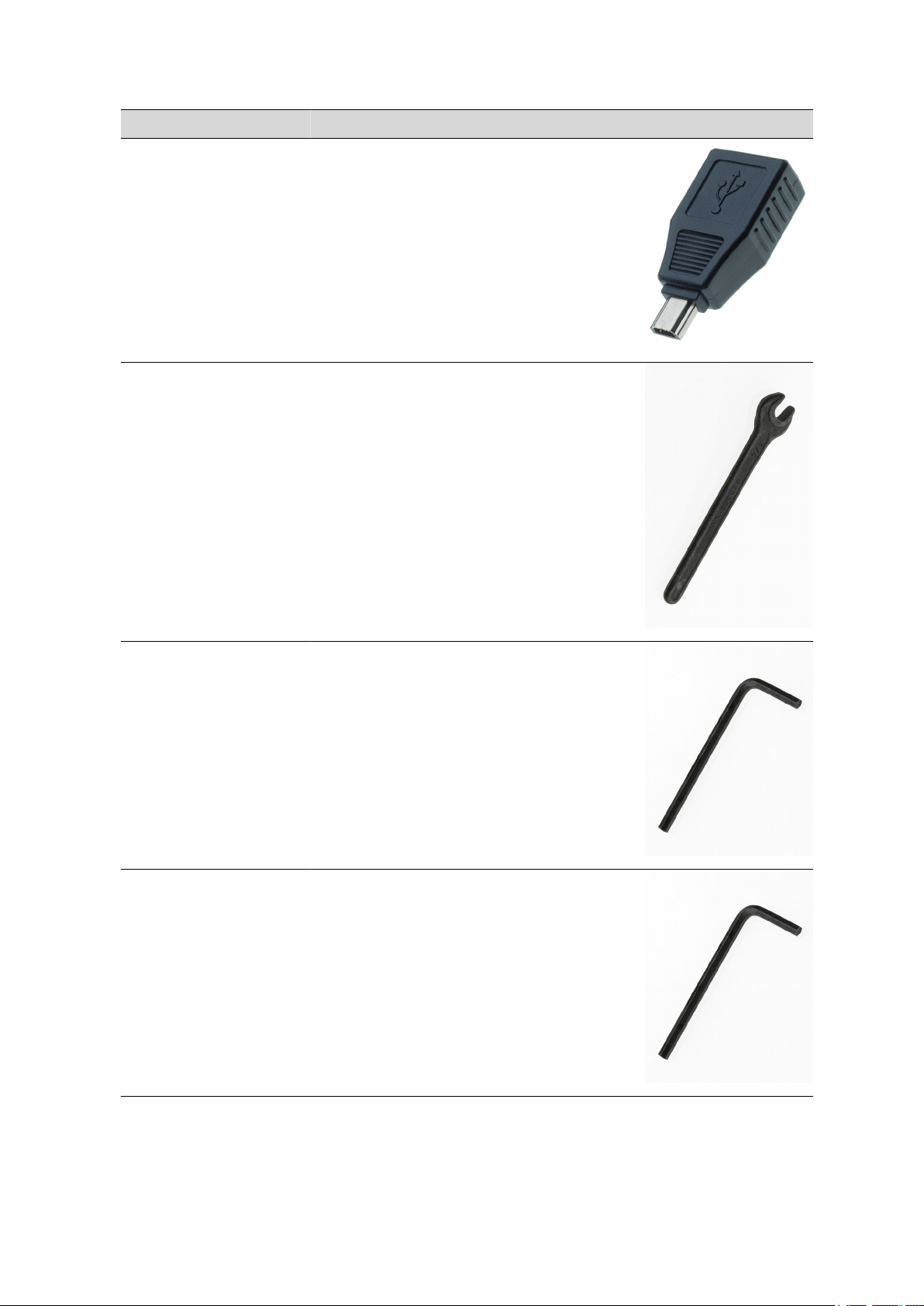
■■■■■■■■■■■■■■■■■■■■■■
Qty. Order no. Description
1 6.2151.100 Adapter USB MINI (OTG) - USB A
For connecting USB instruments.
1 6.2621.090 1/2 in. wrench
For 1/2 in. screws. For IC Sample Processors
Length (mm): 140
13 Accessories
1 6.2621.130 Hexagon key 2 mm
2 mm.
1 6.2621.140 Hexagon key 2.5 mm
863 Compact Autosampler
■■■■■■■■
79
Page 90

13.2 Scope of delivery 2.863.0020 for VA applications
Qty. Order no. Description
1 6.2739.000 Wrench
For tightening connectors
Length (mm): 68
1 6.2743.057 Sample tubes 11 mL
200 pieces. For IC Sample Processors and VA Autosampler
Material: PP
Outer diameter (mm): 16
Length (mm): 108
Volume (mL): 11
■■■■■■■■■■■■■■■■■■■■■■
1 6.2744.070 Pressure screw short
Short version. With UNF 10/32 connection. 5 pieces. For the connection of PEEK capillaries
Material: PEEK
Length (mm): 21
2 6.2744.160 Nozzle/UNF 10/32 coupling with security
device
Security device for connecting pump tubing to a nozzle.
Material: PEEK
■■■■■■■■
80
863 Compact Autosampler
Page 91

■■■■■■■■■■■■■■■■■■■■■■
Qty. Order no. Description
1 6.2751.130 Splash protection for Compact Autosampler
and Compact Sample Changer
Splash protection for safe working with needles (Compact Autosampler) and titration equipment (Compact Sample Changer)
Material: Plexiglas (PMMA)
1 6.2833.030 Needle holder 1/8 in. for 863 Com-
pact Autosampler
Needle holder 1/8 in. for 863 Compact Autosampler
Material: PEEK
Material 2: Stainless steel 18/10
13 Accessories
1 6.2846.000 Sample needle (zirconium oxide)
Sample needle for Sample Processors and Autosamplers in ion chromatography and voltammetry
Material: Ceramic
Outer diameter (inches): 1/8
Inner diameter (mm): 0.75
Length (mm): 151
1 6.2122.0x0 Mains cable with C13 line socket
IEC-60320-C13
Cable plug according to customer requirements.
Switzerland: Type SEV 12
6.2122.020
Germany, …: Type CEE(7), VII
6.2122.040
863 Compact Autosampler
■■■■■■■■
81
Page 92

13.3 Optional accessories for 2.863.0010
Qty. Order no. Description
USA, …: Type NEMA/ASA
6.2122.070
1 8.863.8003EN 863 Compact Autosampler Manual
13.3 Optional accessories for 2.863.0010
Order no. Description
6.1826.310 Pump tubing LFL (orange/green), 3 stoppers
Pump tubing for bromate determination using the triiodide method.
■■■■■■■■■■■■■■■■■■■■■■
6.1826.320 Pump tubing LFL (orange/yellow), 3 stoppers
For suppressor solutions, acceptor solution in Inline Dialysis and for Inline Ultrafiltration
6.1826.330 Pump tubing LFL (orange/white), 3 stoppers
For all IC instruments with peristaltic pump.
■■■■■■■■
82
863 Compact Autosampler
Page 93

■■■■■■■■■■■■■■■■■■■■■■
Order no. Description
6.1826.340 Pump tubing LFL (black/black), 3 stoppers
For the sample solution in inline dialysis
6.1826.380 Pump tubing LFL (gray/gray), 3 stoppers
For Inline Dilution
13 Accessories
6.1826.390 Pump tubing LFL (yellow/yellow), 3 stoppers
For the sample solution in Inline Ultrafiltration.
6.2141.230 Remote cable Compact Sample Changer/Compact
Autosampler - Titrino plus/Pump Station
Cable for the remote connection between Compact Sample Changer/Compact Autosampler and Titrino plus and/or Pump Station.
6.2141.270 Cable Compact IC Autosampler - Remote Connection
on IC Instruments
Enables remote control of the Compact IC Autosampler from IC Instruments
863 Compact Autosampler
■■■■■■■■
83
Page 94

13.3 Optional accessories for 2.863.0010
Order no. Description
6.2151.020 Cable USB A - USB B 1.8 m
USB connecting cable
Length (m): 1.8
6.2629.000 Screw nut to needle holder IC
On Sample Processors
6.2723.310 Protective cover for Titrino plus
Protective cover for display and keypad for all instruments of the Titrino plus
family. Compatible to: 848 Titrino plus 862 Compact Titrosampler 863 Compact
Autosampler 865 Dosimat plus 869 Compact Sample Changer 870 KF Titrino
plus 876 Dosimat plus 877 Titrino plus <FONT style="BACKGROUND-COLOR:
#fafafa">Material: PVC</FONT>
Material: PVC
■■■■■■■■■■■■■■■■■■■■■■
6.2743.040 Sample tubes 2.5 mL
2.5 mL. 2000 pieces. For IC Sample Processors
Material: PP
Volume (mL): 2.5
■■■■■■■■
84
863 Compact Autosampler
Page 95

■■■■■■■■■■■■■■■■■■■■■■
Order no. Description
6.2743.047 Sample tubes 2.5 mL
2.5 mL. 200 pieces. For IC Sample Processors
Material: PP
Volume (mL): 2.5
6.2743.050 Sample tubes 11 mL
2000 pieces. For IC Sample Processors and VA Autosampler
Material: PP
Outer diameter (mm): 16
Length (mm): 108
Volume (mL): 11
13 Accessories
6.5333.000 IQ/OQ Kit for IC
The IQ/OQ Kit for IC contains all parts and standard solutions required for IQ/OQ
in IC.
6.6059.221 MagIC Net™ 2.2 Compact CD: 1 Licence
Professional PC program for controlling one intelligent Compact IC instrument
and one autosampler or one 771 Compact Interface. The software permits control, data acquisition, evaluation and monitoring as well as report generation for
ion chromatographic analyses. Graphic user interface for routine operations,
extensive database programs, method development, configuration and manual
system control, highly flexible user administration, efficient database operations,
extensive data export functions, individually configurable report generator, control and monitoring of all system components and the chromatographic results.
MagIC Net™ Compact complies with FDA regulation 21 CFR Part 11 as well as
GLP. Dialogue languages: German, English, French, Spanish, Chinese, Korean,
Japanese and more. 1 licence.
863 Compact Autosampler
■■■■■■■■
85
Page 96

13.3 Optional accessories for 2.863.0010
Order no. Description
6.6059.222 MagIC Net™ 2.2 Professional CD: 1 Licence
Professional PC program for controlling intelligent Professional IC systems, Compact IC instruments and their peripherals such as different autosamplers, 800
Dosinos dosing systems, 771 Compact Interface, etc. The software permits control, data acquisition, evaluation and monitoring as well as report generation for
ion chromatographic analyses. Graphic user interface for routine operations,
extensive database programs, method development, configuration and manual
system control, highly flexible user administration, efficient database operations,
extensive data export functions, individually configurable report generator, control and monitoring of all system components and the chromatographic results.
MagIC Net™ Professional complies with FDA regulation 21 CFR Part 11 as well
as GLP. Dialogue languages: German, English, French, Spanish, Chinese, Korean,
Japanese and more. 1 licence.
6.6059.223 MagIC Net™ 2.2 Multi CD: 3 Licences
Professional PC program for controlling intelligent Professional IC systems, Compact IC instruments and their peripherals such as different autosamplers, 800
Dosino, 771 Compact Interface, etc. The software permits control, data acquisition, evaluation and monitoring as well as report generation for ion chromatographic analyses. Graphic user interface for routine operations, extensive database programs, method development, configuration and manual system control; highly flexible user administration, efficient database operations, extensive
data export functions, individually configurable report generator, control and
monitoring of all system components and the chromatographic results.
MagIC Net™ Multi complies with FDA regulation 21 CFR Part 11 as well as GLP.
Dialogue languages: German, English, French, Spanish, Chinese, Korean, Japanese and more. Client-Server version with 3 licences.
■■■■■■■■■■■■■■■■■■■■■■
6.9988.633 Validation Documentation for 863 (English / German)
– CD
8.862.3003EN ETL Certificate 86x Sample changers, English
8.863.3002EN Declaration of conformity: 863 Compact Autosampler
(English)
■■■■■■■■
86
863 Compact Autosampler
Page 97

■■■■■■■■■■■■■■■■■■■■■■
13.4 Optional accessories for 2.863.0020
Order no. Description
2.843.0040 843 VA Membrane Pump Station
The 843 Membrane Pump Station is equipped with two membrane pumps that
can be directly controlled via remote signals from the 797 VA Computrace. The
voltammetry version includes all accessories for the automatic emptying and
rinsing of the measuring vessel.
Dimensions in mm (W/H/D): 160/410/310
2.843.0140 843 VA Peristaltic Pump Station
The 843 Peristaltic Pump Station is equipped with two peristaltic pumps that can
be directly controlled via remote signals from the 797 VA Computrace. The voltammetry version includes all accessories for the automatic emptying and rinsing
of the measuring vessel.
Dimensions in mm (W/H/D): 160/400/300
13 Accessories
6.2723.310 Protective cover for Titrino plus
Protective cover for display and keypad for all instruments of the Titrino plus
family. Compatible to: 848 Titrino plus 862 Compact Titrosampler 863 Compact
Autosampler 865 Dosimat plus 869 Compact Sample Changer 870 KF Titrino
plus 876 Dosimat plus 877 Titrino plus <FONT style="BACKGROUND-COLOR:
#fafafa">Material: PVC</FONT>
Material: PVC
6.2743.050 Sample tubes 11 mL
2000 pieces. For IC Sample Processors and VA Autosampler
Material: PP
Outer diameter (mm): 16
Length (mm): 108
Volume (mL): 11
863 Compact Autosampler
■■■■■■■■
87
Page 98

Index
Index
■■■■■■■■■■■■■■■■■■■■■■
A
Adapter
Connect ............................. 18
Automation 52, 53, 54
B
Backup ..................................... 47
C
Capillary connections ................ 18
Computer
Connect ............................. 11
Contrast ................................... 46
D
Diagnosis ................................. 51
Dialog language
Load ................................... 50
Dialog type ............................... 45
Directory structure .................... 47
Driver
Install ................................. 11
E
Electrostatic charge .................... 4
Expert dialog ............................ 45
G
GLP .......................................... 57
Guarantee ................................ 69
I
IC instruments
Connect ............................. 21
Initialization .............................. 63
Installation
Driver ................................. 11
Peristaltic pump .................. 15
Pump tubings ..................... 15
Instrument
Switch off ........................... 29
Switch on ........................... 29
Instrument diagnosis ................ 50
Instrument versions .................... 1
K
Keyboard
Connect ............................. 18
Keyboard layout ....................... 49
Keypad
Key assignment .................. 62
L
Language ................................. 44
Language file
Load ................................... 50
Lift
Move ................................. 42
Settings .............................. 48
M
Mains voltage ............................. 4
Maintenance
Peristaltic pump .................. 56
Method .................................... 32
Create ................................ 33
Delete ................................ 47
Export ................................ 35
Import ................................ 47
Load ................................... 35
Save ................................... 33
Method templates .................... 32
N
Navigating ................................ 31
Needle
Mount ................................ 13
Needle holder ........................... 13
Next sample pos. ...................... 37
Number of samples 37, 39
Numerical input ........................ 31
O
Operation
General .............................. 30
Peristaltic pump .................. 56
P
Peristaltic pump
Control ............................... 42
Installation ......................... 15
Maintenance ...................... 56
Operation ........................... 56
Rotational speed ................. 42
Pin assignment ......................... 60
Print ......................................... 40
Printer ................................ 49, 62
Connect ............................. 18
Program version
Update ............................... 50
Pump tubing
Overview ............................ 57
Service life .......................... 56
Pump tubings
Installing ............................. 15
Q
Quality Management ................ 57
R
Remote
Cable ................................. 21
Connections ....................... 21
Connector ............................ 8
Interface ............................. 60
Pin assignment ................... 60
Status diagram ................... 61
Report
Print manually .................... 40
Rinsing
Pump tubing ...................... 56
Routine dialog .......................... 45
S
Safety instructions ...................... 3
Sample rack
Rotate ................................ 41
Sample series
Cancel ................................ 38
Continue ............................ 39
Pause ................................. 38
Perform .............................. 36
Prolong .............................. 39
Shorten .............................. 39
Start ................................... 36
Stop ................................... 38
Serial number ............................. 8
Service ....................................... 3
Service Agreement ................... 57
Stand-alone operation ................ 2
Switch off ................................. 29
Switch on ................................. 29
System initialization .................. 63
T
Text input ................................. 31
Tubing connections .................. 18
■■■■■■■■
88
863 Compact Autosampler
Page 99

■■■■■■■■■■■■■■■■■■■■■■
Index
U
Update ..................................... 50
USB .......................................... 61
Keypad ............................... 62
USB (OTG)
Connector ............................ 8
USB connection cable ............... 11
USB device
Adapter .............................. 18
Connect ............................. 18
User name ................................ 44
V
VA Computrace
Connect ............................. 21
Validation ................................. 57
W
Warranty .................................. 69
Working height ........................ 48
Work position .......................... 48
863 Compact Autosampler
■■■■■■■■
89
 Loading...