

Page 1
793 IC Sample Prep Module
IC Sample Prep Module793
POWER
REMOTE
ON ON
PUMP
OFFOFF
REMOTE
ON
OFF
Met r ohm
ACTUATOR
STEP
CH-9101 Herisau/Schweiz
E-Mail info@metrohm.com
Internet www.metrohm.com
Instructions for Use
8.793.1003
Page 2
CH-9101 Herisau/Switzerland
E-Mail info@metrohm.com
Internet www.metrohm.com
793 IC Sample Prep Module
Instructions for Use
8.793.1003 06.2001 / up
Page 3

Table of contents
Table of contents
1 Introduction
1.1 Instrument description ............................................................................ 1
1.2 Parts and controls .................................................................................... 2
1.3 Information about the Instructions for Use ......................................... 4
1.3.1 Organization.................................................................................. 4
1.3.2 Notation and pictograms.............................................................. 5
1.4 Safety notes............................................................................................... 6
1.4.1 Electrical safety............................................................................. 6
1.4.2 General precautionary rules ......................................................... 6
2 Installation
2.1 Setting up the instrument ....................................................................... 7
2.1.1 Packaging ..................................................................................... 7
2.1.2 Check............................................................................................ 7
2.1.3 Location ........................................................................................ 7
2.1.4 Arrangement of the instruments ................................................... 7
2.2 Mains connection ..................................................................................... 8
2.2.1 Setting the mains voltage ............................................................. 8
2.2.2 Fuses ............................................................................................ 9
2.2.3 Mains cable and mains connection ............................................. 9
2.2.4 Switching the instrument on/off .................................................... 9
2.3 Connection to a Modular IC System for Neutralization ................... 10
2.3.1 Electrical connection................................................................... 10
2.3.2 Connection of the SP Module A ................................................. 11
2.3.3 Settings in the «IC Net 2.1» program.......................................... 16
2.4 Connection to a Modular IC System for Cation Elimination ........... 18
2.4.1 Electrical connection................................................................... 18
2.4.2 Connection of the SP Module A ................................................. 19
2.4.3 Settings in the «IC Net 2.1» program.......................................... 22
............................................................................................
..............................................................................................
1
7
3 Operation
3.1 Handling the SP Module A .................................................................... 23
3.2 Manual operation .................................................................................... 24
3.3 Operation via IC Detector 732 .............................................................. 25
...............................................................................................
4 Malfunctions – Maintenance
4.1 Malfunctions and their rectification .................................................... 28
4.2 Maintenance and servicing................................................................... 30
4.2.1 Care............................................................................................. 30
4.2.2 Maintenance by Metrohm service .............................................. 30
4.2.3 Shutdown .................................................................................... 30
4.2.4 Exchanging the pump tubing ..................................................... 31
4.2.5 Regeneration of the cation exchange material .......................... 32
4.2.6 Cleaning the SP Module A.......................................................... 33
4.2.7 Exchanging the cation exchange material ................................. 35
4.2.8 Braking range adjustment .......................................................... 36
793 IC Sample Prep Module/ 8.793.1003 Instructions for Use
...........................................
23
28
I
Page 4

Table of contents
5 Appendix
5.1 Technical data......................................................................................... 38
5.2 Standard equipment .............................................................................. 40
5.3 Optional accessories ............................................................................. 41
5.4 Warranty and conformity ...................................................................... 42
5.4.1 Warranty.......................................................................................42
5.4.2 EU Declaration of conformity ......................................................43
5.4.3 Certificate of conformity and system validation ..........................44
5.5 Index ......................................................................................................... 45
.................................................................................................
38
List of figures
Fig. 1: Front of the 793 IC Sample Prep Module..........................................................2
: Rear of the 793 IC Sample Prep Module...........................................................3
Fig. 2
Fig. 3
: SP Module A (1.793.0110).................................................................................4
Fig. 4
: Setting the mains voltage ..................................................................................9
Fig. 5
: Connection 793 IC Sample Prep Module -
Modular IC System for Neutralization ..............................................................10
Fig. 6
: Connections at SP Module A...........................................................................12
Fig. 7
: Installing pump tubings ...................................................................................13
Fig. 8
: Connection 793 IC Sample Prep Module -
Modular IC System for cation elimination........................................................18
Fig. 9
: Assembling the actuator..................................................................................34
Fig. 10
: Adjusting the braking range ............................................................................37
793 IC Sample Prep Module/ 8.793.1003 Instructions for Use
II
Page 5

1.1 Instrument description
1 Introduction
1.1 Instrument description
The 793 IC Sample Prep Module consists of a reactor block (SP
Module A) with its corresponding control unit; this contains an addi-
tional 2-channel peristaltic pump.
Inline sample pretreatment like neutralization or cation exchange for ion
chromatographic analyses can be carried out with the cation exchanger
built into the SP Module A. The SP Module A contains three cation ex-
change units which are in turn used for cation exchange, regenerated
with acid and rinsed with water. In order to perform each analysis under
comparable conditions a freshly regenerated cation exchange unit is
normally used. Switching is either carried out automatically by the IC
system or manually. Due to possible interference of sulfate with the IC
determination, perchloric acid is normally used for cation exchanger regeneration of the SP Module A instead of sulphuric acid.
At the control unit the SP Module A can either be switched to the next
position manually or by remote control via the remote interface. The
built-in peristaltic pump, which delivers the solutions required for operating the SP Module A, can also be switched on by remote control or
manually.
The 793 IC Sample Prep Module is particularly suitable for retrofitting a
modular anion IC system for inline sample pretreatment in a simple
manner. Two typical applications are described in detail in these instructions for use: Neutralization (e.g. exchange of Na
Cation Separation (e.g. exchange of heavy metals by H
the 793 IC Sample Prep Module can also be combined with all other
HPLC components currently on the market.
Although in principle the techniques of cation exchange by the 793 IC
Sample Prep Module and suppression by the 753 Suppressor Module
are comparable, the 793 IC Sample Prep Module is not suitable for
chemical suppression after ion chromatographic separation of anions.
+
by H+) and
+
). Of course
793 IC Sample Prep Module/ 8.793.1003 Instructions for Use
1
Page 6
1 Introduction
1.2 Parts and controls
11114
IC Sample Prep Module793
POWER
REMOTE PUMP
ON ON
22223
OFFOFF
36
33
45
44
5
55
REMOTE
ACTUATOR
ON
OFF
67
66
Met r ohm
78
77
STEP
8
88
12 10
1212
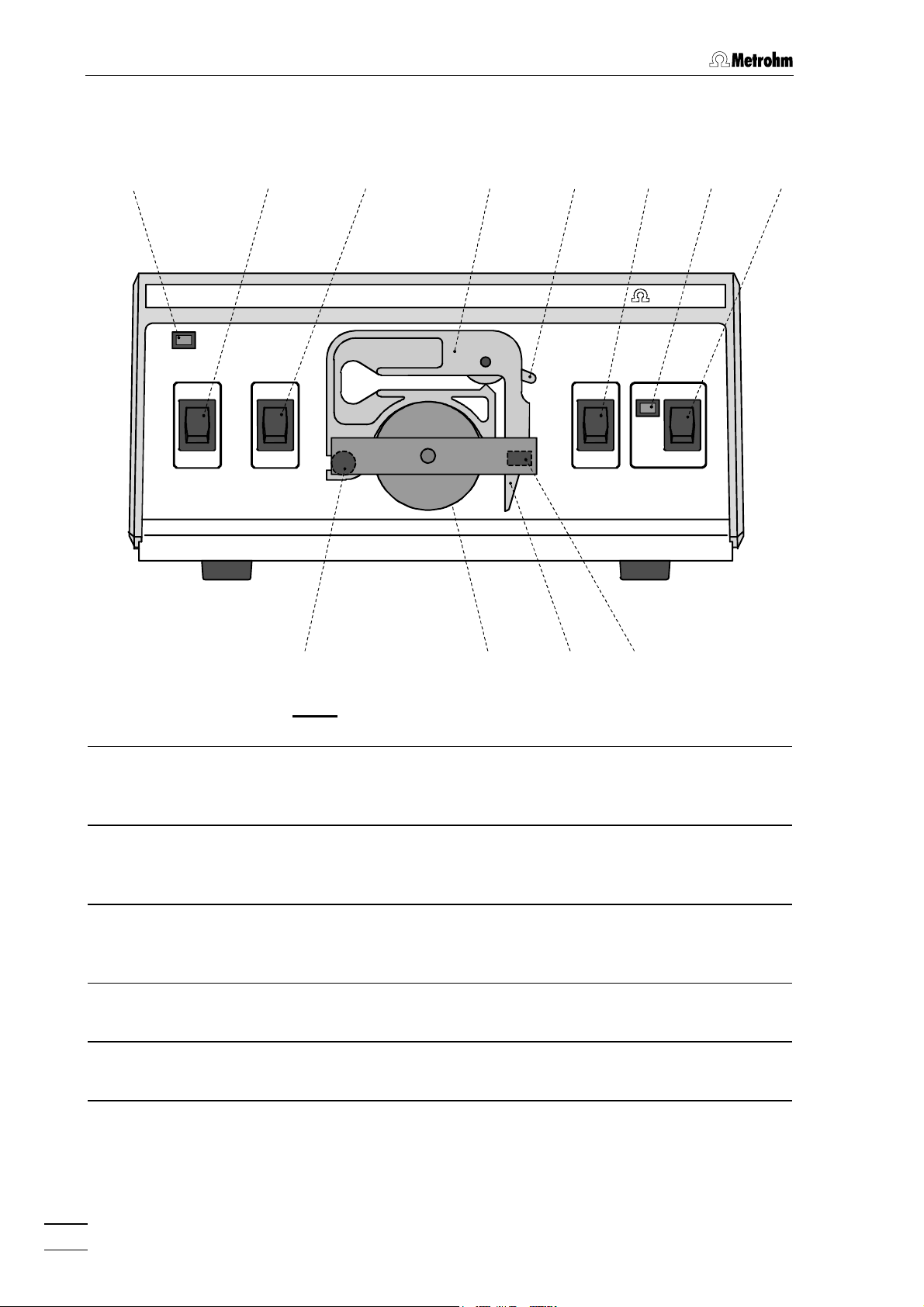
Fig. 1
: Front of the 793 IC Sample Prep Module
1111
Power on lamp
Lights up when instrument is switched
on
2222 Pump Remote ON/OFF
On/Off switch for remote control of the
pump
3333 Pump ON/OFF
On/Off switch for the pump (manual
operation mode)
4444 Tubing cartridge
For 6.1826.010 Pump tubing
5555 Contact pressure lever
For adjusting the contact pressure
6666 SP Module A Remote ON/OFF
On/Off switch for remote control of the
actuator
11
1112
1111
7777 SP Module A position display
Is lit up when the actuator is "in position"
8888 Actuator step
Switches the actuator to the next
position (manual operation mode)
9999 Holding clamp
For locking the tubing cartridge into
place
10
10 Snap-action lever
1010
For releasing the tubing cartridge
11
11 Pump drive
1111
Roller head with contact rollers
12
12 Mounting pin
1212
For attaching the tubing cartridge
10
1010
9999
793 IC Sample Prep Module/ 8.793.1003 Instructions for Use
2
Page 7
1.2 Parts and controls
14
13
1313
Type
1413
1414
WARNING - Fire Hazard -
For continued protection replace only
with the same type and rating of fuse
20
20 16
2020
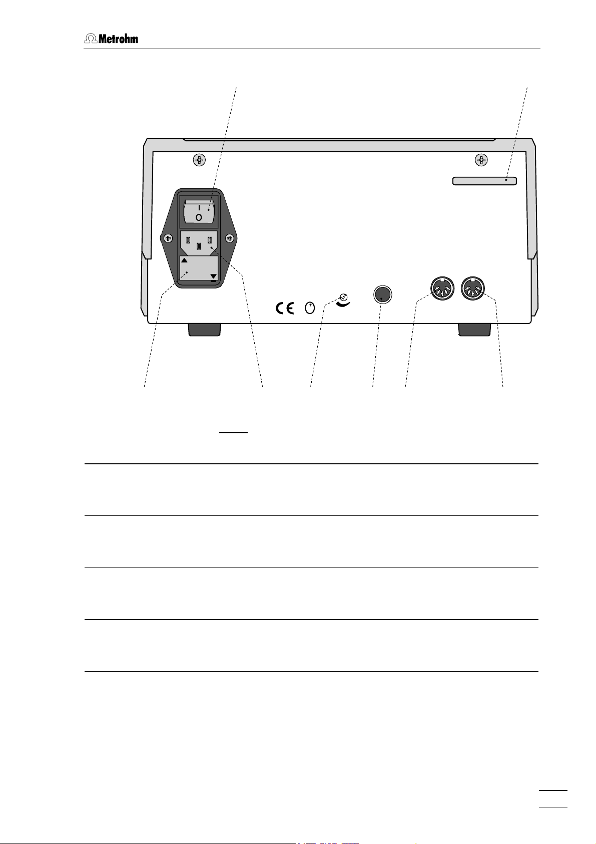
Fig. 2
13
13 Mains switch
1313
For switching the instrument on/off:
I = ON 0 = OFF
110V-120V
220V-240V
50 - 60 Hz 50 VA
0,5A(T)
0,25A(T)
Remote
PumpActuator
A
1718
1717
ActuatorBreakpoint
CB
Made by Metrohm Herisau Switzerland
1617
1616
''''t
S
19
19 15
1919
18
1818
: Rear of the 793 IC Sample Prep Module
17
17 Connection for SP Module A
1717
15
1515
14
14 Serial number 18
1414
15
15 Remote interface for pump
1515
18 Adjustment screw for braking
1818
19
19 Mains connection plug
1919
Remote I/O lines for connection of
external devices (e.g. 732 IC Detector)
16
16 Remote interface for actuator
1616
20
20 Fuse holder
2020
Remote I/O lines for connection of
external devices (e.g. 732 IC Detector)
793 IC Sample Prep Module/ 8.793.1003 Instructions for Use
range
Mains connection, see section 2.2
Changing the fuses, see section 2.2
3
Page 8
1 Introduction
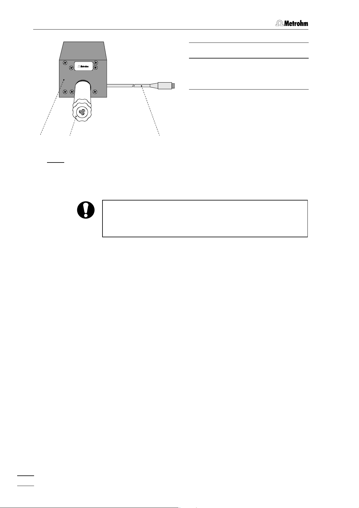
21
21
Reactor block
2121
SP Module A
Ion an alys is
22
22 Actuator connection
2222
with permanently fixed inlet and
outlet capillaries
23
23 Connection cable
2323
Connection cable to control unit
21
21 22
2121
22 23
2222
1
2
3
23
2323
Fig. 3
: 1.793.0110 SP Module A
1.3 Information about the Instructions for Use
Please read through these Instructions for Use carefully before you put
the 793 IC Sample Prep Module into operation. The Instructions for
Use contain information and warnings to which the user must pay
attention in order to assure safe operation of the instruments.
1.3.1 Organization
These Instructions for Use 8.793.1003 for the 793 IC Sample Prep
Module provide a comprehensive overview of the startup procedure,
operation, fault rectification and technical specifications of these instruments. The Instructions for Use are organized as follows:
Section 1 Introduction
Section 2 Installation
Section 3 Operation
Section 4 Faults – Maintenance
Section 5 Appendix
General description of instruments, parts and controls
and safety notes
Setting up, mains connection, attachment of accessories, connection to IC system
Manual operation and operation via 732 IC Detector
Fault rectification, maintenance
Technical data, standard equipment, options, warranty,
declarations of conformity, index
To find the required information on the instruments please use either
the Table of contents or the Index at the back.
793 IC Sample Prep Module/ 8.793.1003 Instructions for Use
4
Page 9
1.3 Information about the Instructions for Use
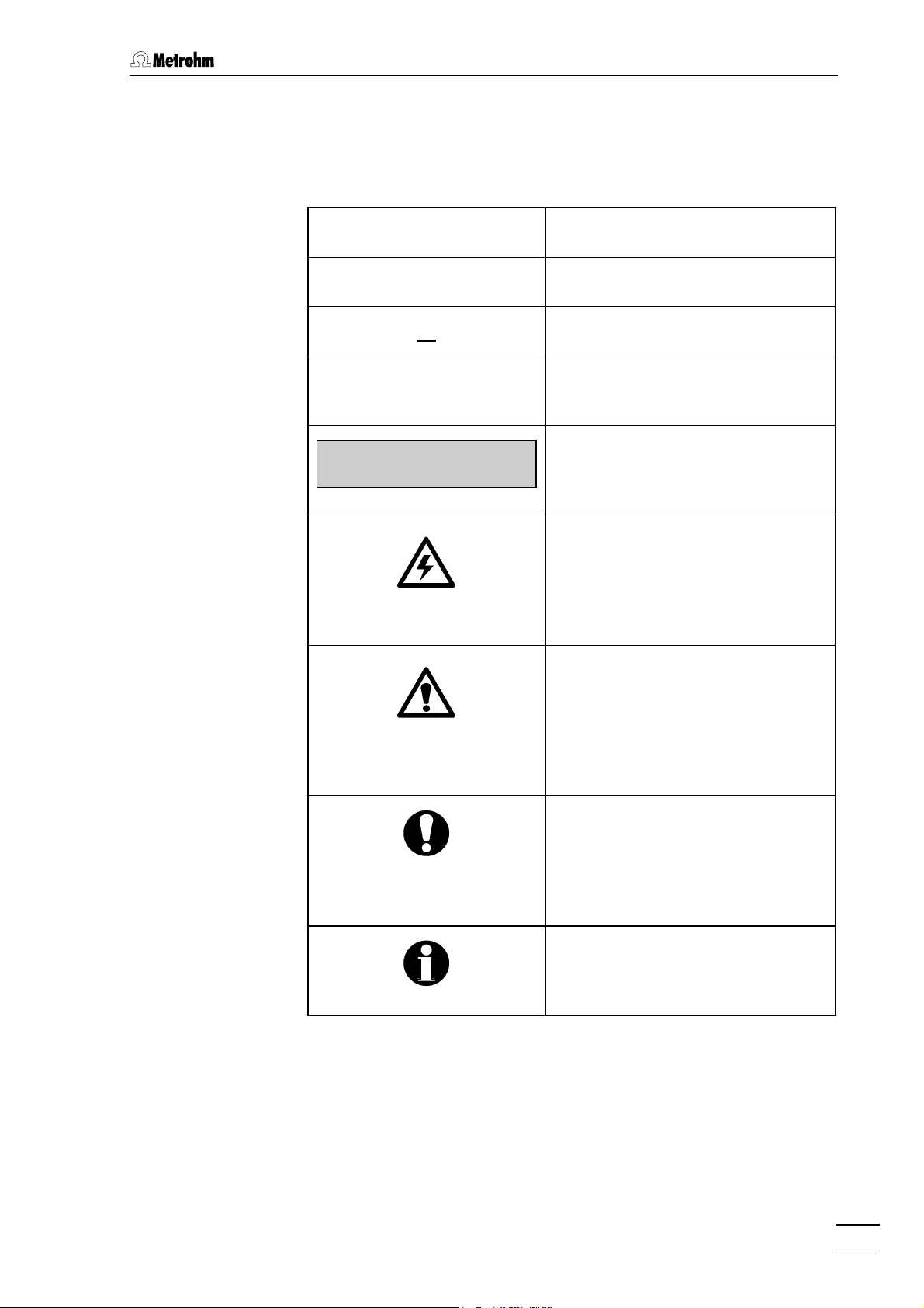
1.3.2 Notation and pictograms
The following notations and pictograms (symbols) are used in these Instructions for Use:
<PUMP> Switch or key
15
15 Part or control of 793
1515
89
89 Part or control of 732/733
8989
"
Range
"
Parameter or entry value
at 732 IC Detector
>PARAM/detector
range: 1.00 mS/cm
Display
Text in display 1111 of the 732 IC
Detector
Hazard
This symbol draws attention to a
possible danger to life or of injury if
the associated directions are not
followed correctly.
Warning
This symbol draws attention to
possible damage to instruments or
instrument parts if the associated
directions are not followed correctly.
Caution
This symbol marks important
information. First read the associated directions before you continue.
793 IC Sample Prep Module/ 8.793.1003 Instructions for Use
Comment
This symbol marks additional
information and tips.
5
Page 10
1 Introduction
1.4 Safety notes
1.4.1 Electrical safety
While electrical safety in the handling of the 793 IC Sample Prep Module is assured in the context of the specifications IEC 1010-1 (protection
class I, degree of protection IP20), the following points should be noted:
x Mains connection
Setting the mains voltage, checking the mains fuse and the mains
connection must be effected in accordance with the instructions in
section 2.2.
x Opening the 793 IC Sample Prep Module
When the 793 IC Sample Prep Module is connected to the power
supply the instrument must neither be opened nor should parts be
removed from it, otherwise there is a danger of coming into contact
with components which are live. Always disconnect the instrument
from all voltage sources before you open it and ensure that the mains
cable is disconnected from mains connection 19
19 !
1919
x Protection against static charges
Electronic components are sensitive to static charging and can be
destroyed by discharges. Before you touch any of the components
inside the 793 IC Sample Prep Module, you should earth yourself and
any tools you are using by touching an earthed object (e.g. housing of
the instrument or a radiator) to eliminate any static charges which
exist.
1.4.2 General precautionary rules
x Handling of solvents
Check all pump tubings and all input and output lines periodically for
possible leaks. Follow the relevant instructions regarding the handling
of flammable and/or toxic solvents and their disposal.
x Regular exchange of pump tubings
Pump tubings are consumable material and must be replaced from
time to time (see Section 4.2.4). Suitable measures must be taken so
that any leak which might occur in the pump tubing or connections
during unattended operation will cause no damage (placing the
instrument at the bottom, collection device for any liquid which may
leak out).
793 IC Sample Prep Module/ 8.793.1003 Instructions for Use
6
Page 11
2.1 Setting up the instrument
2 Installation
2.1 Setting up the instrument
2.1.1 Packaging
The 793 IC Sample Prep Module is supplied together with the separately packed accessories in special packagings containing shockabsorbing foam linings designed to provide excellent protection. The
actual instrument is packed in an evacuated polyethylene bag to prevent the ingress of dust. Please store all these special packagings as
only they can assure damage-free transport of the instrument.
2.1.2 Check
After receipt, immediately check whether the shipment is complete and
has arrived without damage (compare with delivery note and list of
accessories in section 5.2). In the case of transport damage, see
instructions in section 5.4.1 "Warranty".
2.1.3 Location
Position the instruments in the laboratory at a location convenient for
operation, free from vibrations and protected against a corrosive
atmosphere and contamination by chemicals.
2.1.4 Arrangement of the instruments
The best position for the 793 IC Sample Prep Module is beside the Modular IC System (e.g. 733 IC Separation Center).
The 793 IC Sample Prep Module should always be placed at the
bottom of the instrument stack so that any leaks which may occur in
the pump tubing or connections cannot cause damage to the other
instruments by leakage of corrosive liquids (e.g.acid).
793 IC Sample Prep Module/ 8.793.1003 Instructions for Use
7
Page 12
2 Installation
2.2 Mains connection
Follow the instructions below for connecting to the power supply. If
the instrument is operated with the mains voltage set wrongly and/or
wrong mains fuse there is a danger of fire!
2.2.1 Setting the mains voltage
Before switching on the 793 IC Sample Preparation Module for the first
time, check that the mains voltage set on the instrument (see Fig. 2)
matches the local mains voltage. If this is not
the mains voltage on the instrument as follows:
1 Disconnect mains cable
Disconnect mains cable from mains connection plug 19
793 IC Sample Preparation Module.
the case, you must reset
19 of the
1919
2 Remove fuse holder
Using a screwdriver, loosen fuse holder 20
connection 19
3 Check fuse
Carefully take the fuse installed for the desired mains voltage
out of fuse holder 20
of the fuse in the fuse holder is marked by the white arrow
imprinted next to the mains voltage range):
100}}}}120 V 0.5 A (slow-blow) Metrohm No. U.600.0013
220}}}}240 V 0.25 A (slow-blow) Metrohm No. U.600.0010
4 Insert fuse
Change fuse if necessary and reinsert in fuse holder 20
5 Install fuse holder
Depending on the desired mains voltage, insert fuse holder in
the 793 IC Sample Preparation Module so that the corresponding mains voltage range can be read normally and the adjacent
white arrow points to the white bar imprinted below the fuse
holder (see Fig. 4).
19 and take out completely.
1919
20 and check its specifications (the position
2020
20 below the mains
2020
20.
2020
793 IC Sample Prep Module/ 8.793.1003 Instructions for Use
8
Page 13
2.2 Mains connection
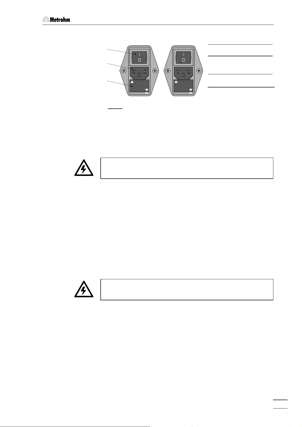
2.2.2 Fuses
13
13
1313
19
19
1919
20
20
2020
220 – 240 V
100 ---- 120 V
220 ---- 240 V
100 – 120 V
220 ---- 240 V
100 ---- 120 V
13
13 Mains switch
1313
19
19 Mains connec-
1919
tion plug
22220000 Fuse holder
Fig. 4
: Setting the mains voltage
One of the two fuses 0.5 A/slow-blow for 100}120 V or 0.25 A/slowblow for 220}240 V is installed in fuse holder 20
20 of the 793 IC Sample
2020
Prep Module as standard.
Ensure that the instrument is never put into operation with fuses of
another type, otherwise there is danger of fire!
For checking or changing fuses, proceed as described in section 2.2.1.
2.2.3 Mains cable and mains connection
Mains cable
The instrument is supplied with one of three mains cables:
x 6.2122.020 with plug SEV 12 (Switzerland, })
x 6.2122.040 with plug CEE(7), VII (Germany, })
x 6.2133.070 with plug NEMA 5-15 (USA, })
which are three-cored and fitted with a plug with an earthing pin. If a different plug has to be fitted, the yellow/green lead (IEC standard) must
be connected to protective earth (protection class I).
Any break in the earthing inside or outside the instrument can make it
a hazard!
Mains connection
Plug the mains cable into mains connection plug 19
Sample Prep Module (see Fig. 4).
19 of the 793 IC
1919
2.2.4 Switching the instrument on/off
The 793 IC Sample Prep Module is switched on and off using mains
switch 13
793 IC Sample Prep Module/ 8.793.1003 Instructions for Use
13. When the instrument is switched on lamp 1111 lights up.
1313
9
Page 14
2 Installation
2.3 Connection to a Modular IC System for Neutralization
An important application for the 793 IC Sample Prep Module is neutralization of an alkaline sample for anion determination by IC with chemical
suppression. Strong bases (e.g. 30 % NaOH) should not be led unlimited to the SP Module A. To provide a sufficient capacity for exchanging
+
by H+ Ions, only a small fraction (e.g. 20 µL) is directed to the SP
Na
Module A using a sample loop. The analyte anions are preconcentrated
subsequently on a preconcentration column and finally eluted to the
separation column in counter flow by the eluent.
Therefore, such an IC system corresponds to the Modular IC System
6 (MIC 6: Anion system with chemical suppression, preconcentration
and matrix elimination) enhanced by the 793 IC Sample Prep Module.
If the sample doesn’t require matrix elimination and preconcentration, it
can be treated directly by the SP Module A. This could be an option for
samples containing only low amounts of the cations which have to be
eliminated. For this purpose, a system as described in section 2.4
should by used.
The following pages describe the electronic connections of this system
in combination with the 766 IC Sample Processor on the base of full
control by «IC Net 2.1».
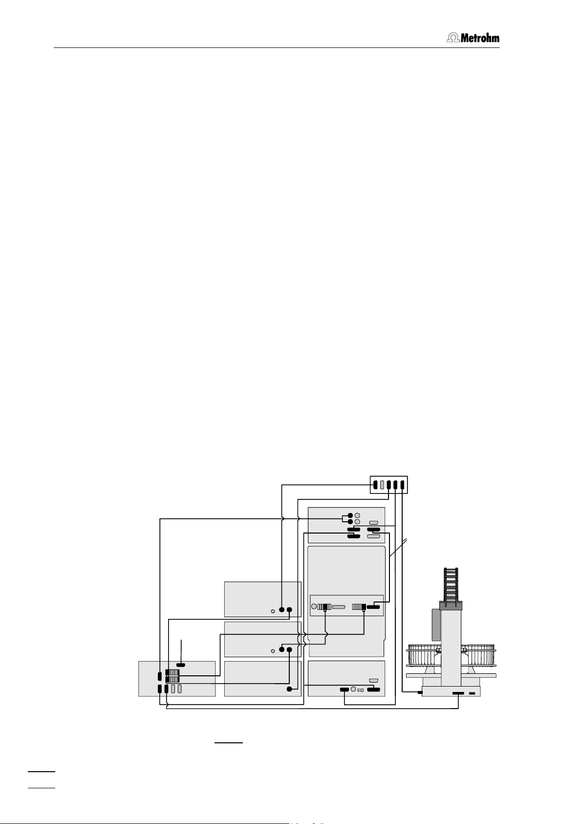
2.3.1 Electrical connection
The 793 IC Sample Prep Module is connected to an IC system consisting of 732 IC Detector, 733 IC Separation Center (two injectors), 709 IC
Pump, 752 IC Pump Unit, 753 IC Suppressor Module and 762 IC Interface as shown in Fig. 5.
6.2128.13 0
793
6.2128.180
753
PC
6.2134.100
6.2143.21 0
6.2125.120
6.2143.200
732
6.2125.090
733
B (LOOP) A (PCC)
6.2128 .180
6.2115.070
762
6.2134.09 0
Fig. 5
752
6.2128.180
709
6.2141.11 0
6.2134.08 0
: Connection 793 IC Sample Prep Module -
Modular IC System for Neutralization
793 IC Sample Prep Module/ 8.793.1003 Instructions for Use
10
Page 15
2.3 Connection to a Modular IC System for Neutralization
A
Please note, that the suppressor of the 753 IC Suppressor Module is
not switched by the 766 Sample Processor program. The remote connection 16
16 (suppressor/actuator) of the 753 IC Suppressor Module is
16 16
connected to the event line “fill” of the 733 valve B instead, using the
6.2128.180 cable. Thus the suppressor is switched when the fill position
is accessed by valve B.
2.3.2 Connection of the SP Module A
The following description implies the usage of the 2.733.0120 IC Separation Center (two injectors).
The 1.793.0110 SP Module A must first be inserted in the 733 IC Separation Center and connected to the 793 IC Sample Prep Module. Additionally, the suppressor block of the 753 Suppressor Module is inserted
and connected, which is described in detail in the corresponding
8.753.1001 Instructions for Use.
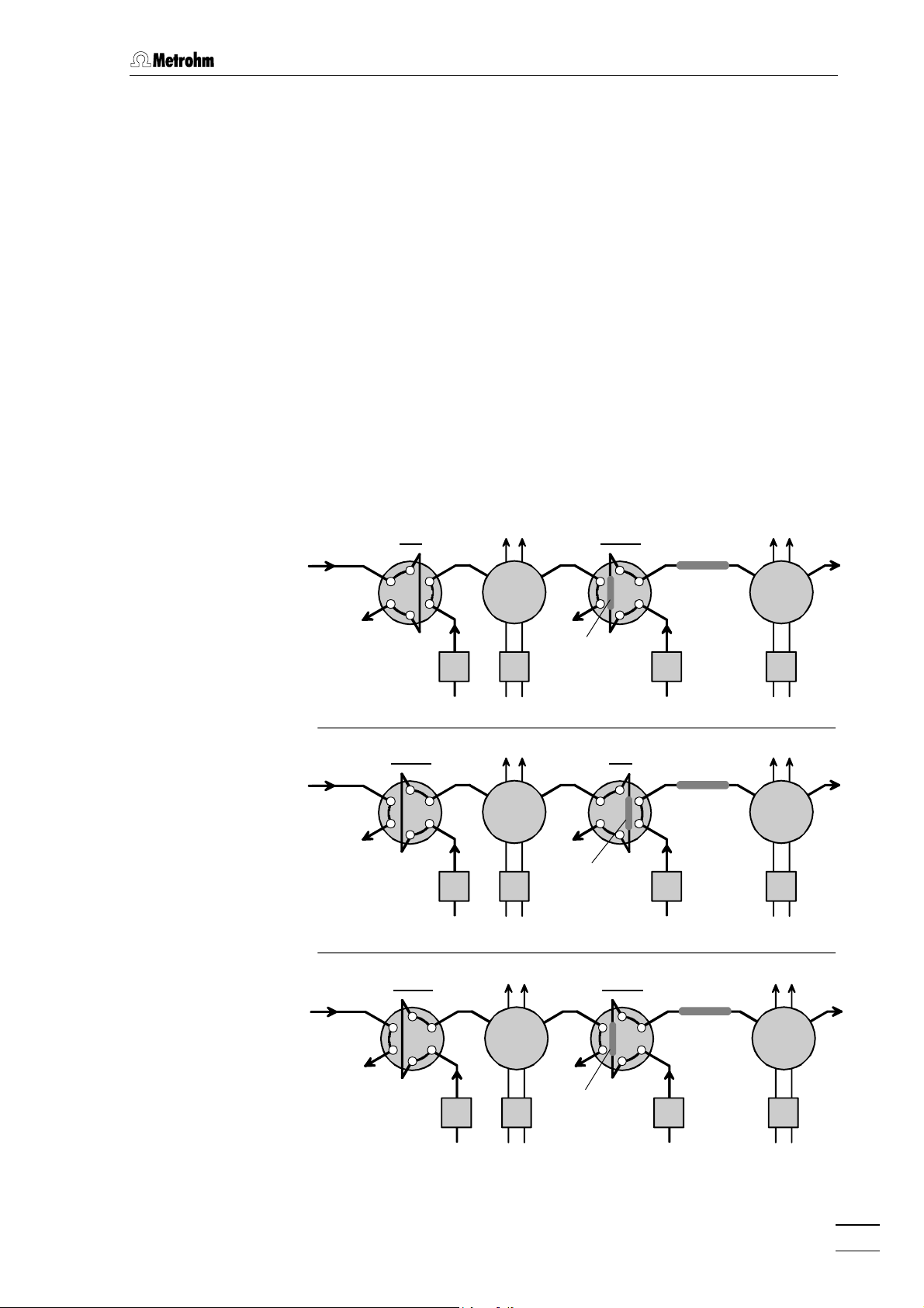
The connection of all parts should be done as described by the following scheme:
) Sample loop at valve B
is filled.
B) Sample is neutralized
by SP Module A;
Anions are preconcentrated via valve A..
sample
sample
Fill Inject
SP
B
Module
A
A
preconcentration
752 793 709
H2O Regenerant RegenerantEluentH2OH
column
Inject Fill
SP
B
Module
A
A
752 793 709
O Regenerant RegenerantEluentH2OH
H
2
preconcentration
column
Inject Inject
separation
column
separation
column
MSM
753
MSM
753
O
2
O
2
C) Preconcentrated
anions are eluted to
the separation column.
793 IC Sample Prep Module/ 8.793.1003 Instructions for Use
sample
SP
B
Module
A
752 793 709
O Regenerant RegenerantEluentH2OH
H
2
preconcentration
column
separation
A
column
MSM
753
O
2
11
Page 16

2 Installation
The inlet and outlet capillaries mounted on the SP Module A are then
connected up. Proceed as follows:
1 Insert SP Module A
x Place SP Module A 21
the 733 Separation Center.
2 Connect SP Module A
x Remove the plastic stopper from opening 41
733 IC Separation Center and push cable 23
SP Module A 21
x Connect cable 23
Sample Prep Module (see Fig. 5).
3 Connect sample line to 793 SP Module A
x Screw inlet capillary 24
A connection 22
valve B using a 6.2744.010 compression fitting.
21 on the floor of the inner chamber of
2121
41 or 43
43 on the
4141
4343
23 mounted on the
2323
21 through the opening.
2121
23 to connection 17
2323
24 marked with "Sample in" at SP Module
2424
22 (see Fig. 6) onto connection “5” of injection
2222
17 “Actuator“ of the 793 IC
1717
Regenerant
Waste
Sample in
25
2525
26
26
2626
4 Connect SP Module A to valve A (Preconcentration
column)
x Screw outlet capillary 29
connection “1” of injection valve A using a 6.2744.010 compression fitting.
x Please note, that the preconcentration column at valve A has
to be rinsed in counterflow when switched from “Fill” to “Inject”.
24
24
2424
29
2925
2929
1
2
3
28
28
2828
27
27
2727
Sample out
H2O
29 marked with “Sample out” onto
2929
24
24 Inlet capillary for sample
2424
25
25 Inlet capillary for acid
2525
26
26 Outlet capillary for acid
2626
27
27 Outlet capillary for H2O
2727
28
28 Inlet capillary for H2O
2828
29
29 Outlet capillary for sample
2929
: Connections at SP Module A
Fig. 6
793 IC Sample Prep Module/ 8.793.1003 Instructions for Use
12
Waste
Page 17

2.3 Connection to a Modular IC System for Neutralization
5 Attach pump tubings
x Loosen both tubing cartridges 4444 from the holding clamp 9999 by
pressing down snap-action lever 10
ing pin 12
x Press contact pressure lever 5555 on both tubing cartridges
down as far as it will go.
x Insert a length of pump tubing 33
into each of the tubing cartridges as shown in Fig. 7. The
white-white stopper 34
holder on the left-hand side of the tubing cartridge.
x Place the tubing cartridges on mounting pin 12
down on the right-hand side until snap-action lever 10
into position on holding clamp 9999. Take care that no kinks are
formed in the pump tubing.
30
30 32
3030
32 33
31 31
3232
3131
33 34
3333
34 44445
3434
12 on 793 Sample Prep Module (see Fig. 1).
1212
34 must click into the corresponding
3434
534
10 36
55
1010
10 and remove from mount-
1010
33 (6.1826.010, ~1.3 mL/min)
3333
12 and press
1212
10 clicks
1010
34 35
3434
35 25/28
3535
3631
3636
31
3131
25/2810
25/2825/28
: Installing pump tubings
Fig. 7
4444
Tubing cartridge 31
5555 Contact pressure lever 32
10
10 Snap-action lever 33
1010
25
25 SP Module A inlet capillary
2525
for HClO
28
28 SP Module A inlet capillary
2828
for H
30
30 PTFE tubing (6.1803.020) 36
3030
4
O
2
31 PEEK compression fitting
3131
(6.2744.010)
32 PEEK coupling (6.2744.030)
3232
33 Pump tubing (6.1826.010)
3333
34
34 Stopper (white-white)
3434
35
35 PEEK coupling (6.2744.110)
3535
36 PEEK filter unit (6.2821.100)
3636
793 IC Sample Prep Module/ 8.793.1003 Instructions for Use
13
Page 18

2 Installation
6 SP Module A connection 2: Regenerant
x Pull the inlet capillary 25
Module A connection 22
panel openings 41
x Mount a PEEK compression fitting 31
end of inlet capillary and screw this on to PEEK filter unit 36
25 marked with “Regenerant“ at SP
2525
22 (see Fig. 6) through one of the rear
2222
or 43
43 of the 733 IC Separation Center.
41
4343
4141
31 (6.2744.010) on the
3131
36
3636
(6.2821.100) (see Fig. 7).
x Mount coupling 35
35 on to the inlet of the PEEK filter unit and
3535
push this coupling on to outlet end of the first pump tubing
33
33 (see Fig. 7).
3333
x Mount suction tubing: cut a piece of PTFE Tubing 30
30
3030
(6.1803.020) to the desired length.
x Mount a PEEK compression fitting 31
end of PTFE tubing 30
30 and screw this on to coupling 32
3030
31 (6.2744.010) on one
3131
32 (see
3232
Fig. 7).
x Push coupling 32
33
33 (see Fig. 7).
3333
32 on to the inlet end of the first pump tubing
3232
x Immerse the other end of the suction tubing in a vessel
containing regeneration solution (normally 20 mmol/L HClO
)
4
and fix in place.
x Pull outlet capillary 26
connection 22
openings 41
22 (see Fig. 6) through one of the rear panel
2222
41 or 43
4141
x Lead outlet capillary 26
26 marked with "Waste" at SP Module A
2626
43 of the 733 IC Separation Center.
4343
26 to a sufficiently large waste container
2626
and fix in place.
7 SP Module A connection 3: H2O
x Pull the inlet capillary 28
connection 22
nings 41
22 (see Fig. 6) through one of the rear panel ope-
2222
or 43
43 of the 733 IC Separation Center.
41
4343
4141
x Mount a PEEK compression fitting 31
end of inlet capillary 28
PEEK filter unit 36
x Mount coupling 35
28 marked with “H2O“ at SP Module A
2828
31 (6.2744.010) on the
3131
28 and screw this on to the second
2828
36 (6.2821.100) (see Fig. 7).
3636
35 on to the inlet of the PEEK filter unit and
3535
push this coupling on to outlet end of the second pump tubing 33
33 (see Fig. 7).
3333
x Mount suction tubing: cut a piece of PTFE Tubing 30
(6.1803.020) to the desired length.
x Mount a PEEK compression fitting 31
end of PTFE tubing 30
30 and screw this on to coupling 32
3030
31 (6.2744.010) on one
3131
Fig. 7).
x Push coupling 32
tubing 33
33 (see Fig. 7).
3333
32 on to the inlet end of the second pump
3232
x Immerse the other end of the suction tubing in a vessel con-
taining rinsing solution (normally dist. H
x Pull outlet capillary 27
connection 22
nings 41
22 (see Fig. 6) through one of the rear panel ope-
2222
or 43
43 of the IC Separation Center 733.
41
4343
4141
x Lead outlet capillary 27
27 marked with “Waste“ at SP Module A
2727
27 to a sufficiently large waste container
2727
O) and fix in place.
2
and fix in place.
30
3030
32 (see
3232
793 IC Sample Prep Module/ 8.793.1003 Instructions for Use
14
Page 19

2.3 Connection to a Modular IC System for Neutralization
8 Startup of 793 IC Sample Prep Module
x Set switch <REMOTE> 2222 to "OFF".
x Switch on 793 IC Sample Prep Module with mains switch 13
13
1313
and set switch <PUMP> 3333 to "ON".
x Adjust the contact pressure for both tubing cartridges: press
contact pressure lever 5555 upwards until the solutions just start
to be drawn in. Then press the contact pressure lever upwards until it clicks once more to obtain optimal contact pressure.
x Check all tubing from the storage vessels through the tubing
cartridges and the SP Module A up to the waste containers
for leakage of liquids. If liquid escapes anywhere the corresponding compression fitting must be tightened further or
changed.
x Before using the SP Module A for sample pretreatment, its
cation exchange material should be conditioned. Inject 30%
sodium hydroxide 15 times (five injections per unit) using the
sample program of the system “Neutralization” as described
in the following section. The run time can be 20 min. each
while the separation column doesn’t have to be installed.
Pump tubings are consumable material with a lifetime which depends
on the contact pressure. This is why the tubing cartridges should be
raised completely by loosening snap-action lever
10
10
on the right-hand
1010
side if the pump is to remain switched off for a considerable length of
time (the set contact pressure remains unchanged).
793 IC Sample Prep Module/ 8.793.1003 Instructions for Use
15
Page 20

2 Installation
2.3.3 Settings in the «IC Net 2.1» program
During configuration of the 793 IC Sample Prep Module and 753 Suppressor Module the IC Net assistant “New system wizard” requires the
definition of “Event lines” for the SP Module A and suppressor, respectively. Although these lines are not installed you must enter any unused
“Event line” to enable the program to proceed. Actually, the SP Module
A is controlled by the 766 sample processor, while the suppressor is
controlled by the event line from 733 valve B (see Fig. 5).
A main program for the system “neutralization.smt“ is defined together
with two programs for extra systems for the 766 IC Sample Processor.
“start-neutralization.smt“ starts the 752 Pump. Furthermore, the SP
Module A is rinsed at all three positions. “end-neutralization.smt“ turns
off the 752 Pump..
The peristaltic pumps of the 753 IC Suppressor Module and 793 IC
Sample Prep Module are started when the IC system is activated
(measuring baseline). For this, the option ’Start pump with startup
hardware
hardware’ has to be selected for both devices.
hardwarehardware
neutralization.smt
Start pump with startup
Start pump with startup Start pump with startup
1. Program for the 766 IC Sample Processor:
001 Ctrl INIT 732
002 Move sample
003 Lift work
004 Ctrl FILL B / STEP 1
005 Pump 120 s
006 Ctrl FILL A 1
007 Ctrl INJECT B1
008 Wait 60 s
009 Ctrl ZERO 1
010 Ctrl INJECT A1
011 Ctrl STEP MSM 753
(*) The time for pumping the sample to the SP Module A should be as small as
possible to avoid contamination of the subsequent preconcentration column
by other anions from the water used for this line. For this reason, calibration
procedures should include blank measurements with this water.
Initialize remote interface
Move needle to sample position
Place lift with needle to working position
Switch injection valve B at 733 to "Fill"
Fill first sample loop (B) with sample
Switch injection valve A at 733 to "Fill"
Switch injection valve B at 733 to "Inject"
Pump sample to sample loop A via SP Module A (*)
Trigger autozero at 732 IC Detector
Switch injection valve A at 733 to "Inject"
Switch SP Module A to next position
793 IC Sample Prep Module/ 8.793.1003 Instructions for Use
16
Page 21

2.3 Connection to a Modular IC System for Neutralization
start-neutralization.smt
2. Save the system file “neutralization.smt” with a new name “startneutralization.smt“.
3. Remove the data recorder by clicking on the recorder icon with the
right mouse button an selecting 'unlink'.
4. Change this program for 'start-neutralization.smt' as follows and save
it again:
001 Ctrl INIT 732
002 Ctrl PUMP 752 on
003 Wait 300 s
004 Ctrl STEP MSM 753
005 Wait 300 s
006 Ctrl STEP MSM 753
007 Wait 300 s
end-neutralization.smt
5. Save the program for “start-neutralization.smt“ under a new name
„end-neutralization.smt“.
6. Change the program for “end-neutralization.smt' as follows and save
it again:
001 Ctrl INIT 732
002 Ctrl PUMP 752 off
Initialize remote interface
Start 752 Pump Unit
Rinsing time
Switch SP Module A to next position
Rinsing time
Switch SP Module A to next position
Rinsing time
Initialize remote interface
Stop 752 Pump Unit
7. The sample queue then contains the following entries, for example:
System Ident Vial Chrom.-No.
1
Start-Neutralization.smt dummy 1
2
Neutralization.smt Probe 1 1
3
Neutralization.smt Probe 2 2
4
Neutralization.smt Probe 3 3
5
Neutralization.smt Probe 4 4
6
Neutralization.smt Probe 5 5
7
End-Neutralization.smt dummy 5
This example describes the processing of a queue with five samples.
The column 'Chrom. No.' is just given for information.
793 IC Sample Prep Module/ 8.793.1003 Instructions for Use
1
2
3
4
5
-
17
Page 22

2 Installation
2.4 Connection to a Modular IC System for Cation Elimination
A second application for the 793 IC Sample Prep Module is cation
elimination before chromatographic separation of the sample on the
column (e.g. precolumn elimination of heavy metals). In this section a
system for determination of anions with chemical suppression is
described. It includes the application of the sample to the SP Module A
followed by filling the sample loop with this pretreated sample.
Therefore, such an IC system corresponds to the Modular IC System
2 (MIC 2: Anion system with chemical suppression) enhanced by the
793 IC Sample Prep Module.
If you are not sure about the required capacity for complete cation
elimination and/or if the sample requires matrix elimination and preconcentration in combination with cation elimination by the SP Module A, a
system as described in section 2.3 should by used.
The following pages describe the electronic connections of this system
in combination with the 766 IC Sample Processor on the base of full
control by «IC Net 2.1».
2.4.1 Electrical connection
The 793 IC Sample Prep Module is connected to an IC system
consisting of 732 IC Detector, 733 IC Separation Center (one injector +
MSM), 709 IC Pump, 752 IC Pump Unit and 762 IC Interface as shown
in Fig. 5.
6.2128.13 0
6.2128.180
PC
6.2134.100
762
793
752
6.2143.21 0
6.2125.120
732
6.2125.090
733
6.2115.070
709
6.2128.180
Abb. 8
6.2134.09 0
: Connection 793 IC Sample Prep Module -
6.2141.11 0
6.2134.08 0
Modular IC System for cation elimination
793 IC Sample Prep Module/ 8.793.1003 Instructions for Use
18
Page 23

2.4
A
2.4 Connection
Connection to
2.42.4
ConnectionConnection
to aaaa Modular
toto
2.4.2 Connection of the SP Module A
The following description implies the usage of the 2.733.0130 IC
Separation Center (one injector + MSM).
The 1.793.0110 SP Module A must first be inserted in the 733 IC
Separation Center and connected to the 793 IC Sample Prep Module.
The connection of all parts should be done as described by the
following scheme:
Modular IC
ModularModular
Fill
IC System
ICIC
System for Cation Elimination
SystemSystem
) In the SP Module A
Cations of the sample
are continuously
exchanged by H
+
;
Sample loop is filled.
B) Pretreated sample is
pumped to the
separation column.
Sample
Sample
Regenerant H
SP
Module
A
793 709
SP
Module
A
793 709
O
2
A
Inject
A
Separation
column
RegenerantEluent H
Separation
column
RegenerantEluent H2O
MSM
752
MSM
752
ORegenerant H2O
2
The inlet and outlet capillaries mounted on the SP Module A are then
connected up. Proceed as follows:
1 Insert SP Module A
x Place SP Module A 21
the 733 Separation Center.
2 Connect SP Module A
x Remove the plastic stopper from opening 41
733 IC Separation Center and push cable 23
SP Module A 21
x Connect cable 23
Sample Prep Module (see Fig. 8).
3 Connect sample line to 793 SP Module A
x Screw inlet capillary 24
A connection 22
coupling using a 6.2744.010 compression fitting. Connect
this PEEK coupling with the PEEK capillary from the 766 IC
Sample Processor using a 6.2744.010 compression fitting.
793 IC Sample Prep Module/ 8.793.1003 Instructions for Use
21 on the floor of the inner chamber of
2121
41 or 43
43 on the
4141
4343
23 mounted on the
2323
21 through the opening.
2121
23 to connection 17
2323
24 marked with "Sample in" at SP Module
2424
22 (see Fig. 6) onto a 6.2744.040 PEEK
2222
17 “Actuator“ of the 793 IC
1717
19
Page 24

2 Installation
4 Connect SP Module A to valve A
x Screw outlet capillary 29
29 marked with “Sample out” onto
2929
connection “1” of injection valve A using a 6.2744.010
compression fitting.
5 Attach pump tubings
x Loosen both tubing cartridges 4444 from the holding clamp 9999 by
pressing down snap-action lever 10
mounting pin 12
12 on 793 Sample Prep Module (see Fig. 1).
1212
10 and remove from
1010
x Press contact pressure lever 5555 on both tubing cartridges
down as far as it will go.
x Insert a length of pump tubing 33
33 (6.1826.010, ~1.3 mL/min)
3333
into each of the tubing cartridges as shown in Fig. 7. The
white-white stopper 34
34 must click into the corresponding
3434
holder on the left-hand side of the tubing cartridge.
x Place the tubing cartridges on mounting pin 12
down on the right-hand side until snap-action lever 10
12 and press
1212
10 clicks
1010
into position on holding clamp 9999. Take care that no kinks are
formed in the pump tubing.
6 SP Module A connection 2: Regenerant
x Pull the inlet capillary 25
Module A connection 22
panel openings 41
x Mount a PEEK compression fitting 31
25 marked with “Regenerant“ at SP
2525
22 (see Fig. 6) through one of the rear
2222
or 43
43 of the 733 IC Separation Center.
41
4343
4141
31 (6.2744.010) on the
3131
end of inlet capillary and screw this on to PEEK filter unit 36
(6.2821.100) (see Fig. 7).
x Mount coupling 35
35 on to the inlet of the PEEK filter unit and
3535
push this coupling on to outlet end of the first pump tubing
33
33 (see Fig. 7).
3333
x Mount suction tubing: cut a piece of PTFE Tubing 30
(6.1803.020) to the desired length.
x Mount a PEEK compression fitting 31
end of PTFE tubing 30
30 and screw this on to coupling 32
3030
31 (6.2744.010) on one
3131
Fig. 7).
x Push coupling 32
33
33 (see Fig. 7).
3333
32 on to the inlet end of the first pump tubing
3232
x Immerse the other end of the suction tubing in a vessel
containing regeneration solution (normally 20 mmol/L HClO
and fix in place.
x Pull outlet capillary 26
connection 22
openings 41
22 (see Fig. 6) through one of the rear panel
2222
41 or 43
4141
x Lead outlet capillary 26
26 marked with "Waste" at SP Module A
2626
43 of the 733 IC Separation Center.
4343
26 to a sufficiently large waste container
2626
and fix in place.
30
3030
32 (see
3232
36
3636
)
4
793 IC Sample Prep Module/ 8.793.1003 Instructions for Use
20
Page 25

2.4
2.4 Connection
2.42.4
7 SP Module A connection 3: H2O
x Pull the inlet capillary 28
connection 22
openings 41
x Mount a PEEK compression fitting 31
end of inlet capillary 28
PEEK filter unit 36
x Mount coupling 35
push this coupling on to outlet end of the second pump
tubing 33
x Mount suction tubing: cut a piece of PTFE Tubing 30
(6.1803.020) to the desired length.
x Mount a PEEK compression fitting 31
end of PTFE tubing 30
x Push coupling 32
tubing 33
x Immerse the other end of the suction tubing in a vessel con-
taining rinsing solution (normally dist. H
x Pull outlet capillary 27
connection 22
openings 41
x Lead outlet capillary 27
and fix in place.
Connection to
ConnectionConnection
41
4141
33 (see Fig. 7).
3333
33 (see Fig. 7).
3333
41
4141
to aaaa Modular
Modular IC
toto
ModularModular
28 marked with “H2O“ at SP Module A
2828
22 (see Fig. 6) through one of the rear panel
2222
or 43
43 of the 733 IC Separation Center.
4343
28 and screw this on to the second
2828
36 (6.2821.100) (see Fig. 7).
3636
35 on to the inlet of the PEEK filter unit and
3535
30 and screw this on to coupling 32
3030
32 on to the inlet end of the second pump
3232
27 marked with “Waste“ at SP Module A
2727
22 (see Fig. 6) through one of the rear panel
2222
or 43
43 of the IC Separation Center 733.
4343
27 to a sufficiently large waste container
2727
IC System
System for Cation Elimination
ICIC
SystemSystem
31 (6.2744.010) on the
3131
31 (6.2744.010) on one
3131
O) and fix in place.
2
30
3030
32..
3232
8 Startup of 793 IC Sample Prep Module
x Set switch <REMOTE> 2222 to "OFF".
x Switch on 793 IC Sample Prep Module with mains switch 13
13
1313
and set switch <PUMP> 3333 to "ON".
x Adjust the contact pressure for both tubing cartridges: press
contact pressure lever 5555 upwards until the solutions just start
to be drawn in. Then press the contact pressure lever
upwards until it clicks once more to obtain optimal contact
pressure.
x Check all tubing from the storage vessels through the tubing
cartridges and the SP Module A up to the waste containers
for leakage of liquids. If liquid escapes anywhere the
corresponding compression fitting must be tightened further
or changed.
x Before using the SP Module A for sample pretreatment, its
cation exchange material should be conditioned. Inject 30%
sodium hydroxide 15 times (five injections per unit) using the
sample program of the system “Neutralization” as described
in the following section. The run time can be 20 min. each
while the separation column doesn’t have to be installed.
Pump tubings are consumable material with a lifetime which depends
on the contact pressure. This is why the tubing cartridges should be
raised completely by loosening snap-action lever
side if the pump is to remain switched off for a considerable length of
time (the set contact pressure remains unchanged).
793 IC Sample Prep Module/ 8.793.1003 Instructions for Use
10
10
on the right-hand
1010
21
Page 26

2 Installation
2.4.3 Settings in the «IC Net 2.1» program
During configuration of the 793 IC Sample Prep Module, the IC Net
assistant “New system wizard” requires the definition of an “Event line”
for the SP Module A. Although this is not installed you must enter any
unused “Event line” to enable the program to proceed. Actually, the SP
Module A is controlled by the 766 sample processor (see Fig. 8).
The signal for switching the internal IC Suppressor Module is not
provided by the 766 program. For this purpose, in the IC Net program
the 733 IC Separation Center parameter “Auto Step” must be set to
“fill”.
The peristaltic pumps of the 752 IC Pump Unit and 793 IC Sample Prep
Module are started when the IC system is activated (measuring
baseline). For this , the option ’Start pump with startup hardware
to be selected for both devices.
catex.smt
Start pump with startup hardware’ has
Start pump with startup hardwareStart pump with startup hardware
Program for the 766 IC Sample Processor:
001 Ctrl INIT 732
002 Move sample
003 Lift work
004 Ctrl ZERO 1
005 Ctrl FILL A 1
006 Pump 120 s
007 Ctrl INJECT A1
008 Ctrl STEP MSM 753
Initialize remote interface
Move needle to sample position
Place lift with needle to working position
Trigger autozero at 732 IC Detector
Switch injection valve A at 733 to "Fill"
Pump sample to sample loop via SP Module A (*)
Switch injection valve A at 733 to "Inject"
Switch SP Module A to next position
(*) The time for pumping the sample to the SP Module A should be as small as
possible to minimize the loading of the cation exchange material.
793 IC Sample Prep Module/ 8.793.1003 Instructions for Use
22
Page 27

3.1 Handling the SP Module A
3 Operation
3.1 Handling the SP Module A
General
The SP Module A of the 793 Sample Prep Module consists of a total
of three cation exchange units which are in turn used for cation exchange, regenerated and rinsed with water. In order to record each new
chromatogram under comparable conditions a freshly regenerated
cation exchange unit is normally used. Switching is either carried out
automatically together with valve switching or manually.
Correct connections
The three inlets and outlets numbered 1...3 on the SP Module A each
have 2 permanently mounted PTFE capillaries, which must be connected as described in sections 2.3.2 or 2.4.2 respectively (see Fig. 6).
Flow direction
The cation exchange units must never be regenerated in the same
flow direction used for the sample. You should thus always install the
inlet and outlet capillaries as described in sections 2.3.2 or 2.4.2
respectively according to the scheme shown in Fig. 6.
Never switch when dry
The SP Module A must never
a danger of blocking.
No recycling
The recycling process (returning the eluent to the storage vessel)
must not be carried out when the SP Module A is in operation.
be switched in the dry state as there is
793 IC Sample Prep Module/ 8.793.1003 Instructions for Use
23
Page 28

3 Operation
3.2 Manual operation
The 793 IC Sample Prep Module cannot be manually operated unless
the installation has been carried out properly as described in section 2
(mains connection, attaching the pump tubing, connection to the IC
system).
REMOTE
PUMP
Switch instrument on/off
The 793 IC Sample Prep Module is switched on and off using
mains switch 13
I Instrument switched on
13 on the rear of the instrument (see Fig. 2):
1313
0 Instrument switched off
POWER
After the instrument has been switched on the power lamp 1111
lights up to show that the instrument is ready for use.
Switch off remote control of the pump
ON
In order to allow manual operation the remote control of the
pump must be switched off with switch 2222.
ON Remote control switched on
OFF
OFF Remote control switched off
Switch pump on/off
ON
The drive of the pump is switched on and off with the switch 3333
<PUMP>:
ON Pump switched on
OFF
OFF Pump switched off
REMOTE
ON
Switch off remote control of the SP Module A
In order to allow manual operation the remote control of the SP
Module A must be switched off with switch 6666.
ON Remote control switched on
OFF
ACTUATOR
STEP
OFF Remote control switched off
Rotate SP Module A
The SP Module A is switched to the next position by means of
switch 8888 <STEP>.
The position display 7777 beside the switch shows whether the SP
Module A is in the correct position:
Lamp on Right position
Lamp off Wrong position or blocked
(procedure see section 4.1)
793 IC Sample Prep Module/ 8.793.1003 Instructions for Use
24
Page 29

3.3 Operation via 732 IC Detector
3.3 Operation via 732 IC Detector
When operating the 793 IC Sample Prep Module together with the 732
IC Detector and the 733 IC Separation Center both pump and the SP
Module A on the 793 IC Sample Prep Module can be operated and
switched automatically without the program “IC Net”. To allow direct
remote control of SP Module A and pump by the 732 IC Detector the
793 remote interfaces 15
interface of the 732 IC Detector by means of the 6.2143.210 cable (available as an option).
15 and 16
1515
16 have to be connected to the remote
1616
REMOTE
Switch instrument on/off
The 793 IC Sample Prep Module is switched on and off using
mains switch 13
I Instrument switched on
13 on the rear of the instrument (see Fig. 2):
1313
0 Instrument switched off
POWER
After the instrument has been switched on the power lamp 1111
lights up to show that the instrument is ready for use.
Switch on remote control of the pump
ON
In order to allow remote operation via 732 IC Detector the remote
control must be switched on with switch 2222.
ON Remote control switched on
OFF
OFF Remote control switched off
Automatic pump switch-on when the 732 IC Detector is switched on
In order to start up the pump drive of the 793 IC Sample Prep
Module automatically when the 732 IC Detector is switched on
alterations must be made to the basic settings (Setup, see
section 4.4.1 of 732/733 Manual). The remote output lead 1 must
be set to 1 (on, active, 0 V):
When the 732 IC Detector is switched off the pump at the 793 IC
Sample Prep Module is also switched off.
Switch pump on/off in a program
In the 732 IC Detector the <PROGRAM> key can be used to
create time programs with a maximum of 20 program steps (see
section 4.7.1 of 732/733 Manual). The pump can be switched on
or off at any program step by setting the remote output lead 1 to
1 (on, active, 0 V) or 0 (off, inactive, open) respectively:
793 IC Sample Prep Module/ 8.793.1003 Instructions for Use
>SETUP/output
remote 10000000
25
Page 30

3 Operation
f
REMOTE
Switch on:
Switch off:
>PROGRAM/edit XXX.X min
remote 1
>PROGRAM/edit XXX.X min
remote 0
✴✴✴✴✴✴✴
✴✴✴✴✴✴✴
Switch pump on/off at an event
In the 732 IC Detector the <EVENT> key can be used to
program a maximum of 4 different events (see section 4.7.3 o
732/733 Manual). The pump can be switched on or off at any
event by setting the remote output lead 1 to 1 (on, active, 0 V) or
0 (off, inactive, open) respectively:
Switch on:
Switch off:
EVENT YY-MM-DD HH:MM:SS
remote 1
EVENT YY-MM-DD HH:MM:SS
remote 0
✴✴✴✴✴✴✴
✴✴✴✴✴✴✴
Switch on remote control of the SP Module A
ON
In order to bring the SP Module A automatically to the next
position via the 732 IC Detector the remote control of the SP
Module A must be switched on with switch 6666.
OFF
ON Remote control switched on
OFF Remote control switched off
Rotate SP Module A in a program
In the 732 IC Detector the <PROGRAM> key can be used to
create time programs with a maximum of 20 program steps (see
section 4.7.1 of 732/733 Manual ). With each program step the SP
Module A can be brought to the next position by setting remote
output lead 2 to 1 (on, active, 0 V). This lead must later be
returned to the setting 0 (off, inactive, open) before the SP
Module A can be switched to the next position.
Rotate:
Reset
output lead:
Example
Automatically changing the SP
Module A position in "inject"programs (for manual operation
or with autosamplers).
>PROGRAM/edit XXX.X min
remote ✴1
>PROGRAM/edit XXX.X min
remote ✴0
PROGRAM
progr.type: inject
0.0 remote
0.1 remote
✴✴✴✴✴✴
✴✴✴✴✴✴
✴✴✴✴1✴✴✴✴✴✴✴✴✴✴✴✴✴✴✴✴✴✴✴✴✴✴✴✴
✴✴✴✴0✴✴✴✴✴✴✴✴✴✴✴✴✴✴✴✴✴✴✴✴✴✴✴✴
793 IC Sample Prep Module/ 8.793.1003 Instructions for Use
26
Page 31

3.3 Operation via 732 IC Detector
f
ACTUATOR
STEP
Rotate SP Module A at an event
In the 732 IC Detector the <EVENT> key can be used to
program a maximum of 4 different events (see section 4.7.3 o
732/733 Manual ). At each event the SP Module A can be brought
into the next position by setting remote output lead 2 to 1 (on,
active, 0 V). This lead must later be returned to the setting 0 (off,
inactive, open) before the SP Module A can be switched to the
next position.
Rotate:
Reset
output lead:
EVENT YY-MM-DD HH:MM:SS
remote ✴1
EVENT YY-MM-DD HH:MM:SS
remote ✴0
✴✴✴✴✴✴
✴✴✴✴✴✴
SP Module A position display
The position display 7777 of the 793 IC Sample Prep Module beside
switch 8888 shows whether the SP Module A is in the right position:
Lamp on SP Module A in the right position
Lamp off SP Module A in the wrong position or blocked
(procedure see section 4.1)
793 IC Sample Prep Module/ 8.793.1003 Instructions for Use
27
Page 32

4 Malfunctions - Maintenance
4 Malfunctions – Maintenance
4.1 Malfunctions and their rectification
If difficulties appear with the IC system during analysis, their cause are
best investigated in the order separating column oooo pump oooo eluent
oooo IC system. An overview of possible malfunctions, their causes and
remedies can be found in the instruction manuals of both 690 Ion
Chromatograph (section 6.5) and 732/733 IC System (section 5.3.2).
In addition to these general malfunctions the table below contains others which might arise as a result of the operation of the 793 Sample
Prep Module.
Malfunction Cause Rectification
Insufficient or nonexisting flow rate
Leakage x Leaking tubing connectors x Tighten or replace the leaking tubing
x Contact pressure too low
x Pump tubing faulty
x Contamination of the filter in the
6.2821.100 Filter unit PEEK
x Blocked connections
x SP Module A blocked
x Set contact pressure correctly: Press
contact pressure lever 5555 on the tubing
cartridge down as far as it will go. Press
contact pressure lever 5555 upwards until the
solution just starts to be drawn in. Then
press contact pressure lever upwards until
it clicks once more to obtain optimal
contact pressure.
x Exchange pump tubing
(see section 4.2.4)
x Replace the 6.2821.110 Filter (see
connections description, section 2.3.2)
x Carry out a step-by-step check of the
connections and connectors and if necessary clean or replace them. If the
connections to or from the actuator are
blocked then remove the actuator and
clean it (see section 4.2.6).
x Exchange SP Module A
(see section 4.2.7).
connectors.
Air bubbles in pump
circuit
x Suction tubing is not immersed
x Leaking tubing connectors
x Immerse the suction tubing fully in the
regenerating or rinsing solution.
x Tighten or replace the leaking tubing
connectors.
793 IC Sample Prep Module/ 8.793.1003 Instructions for Use
28
Page 33

4.1 Malfunctions and their rectification
Actuator moves to next
position but display lamp
7777 no longer lights up
Actuator is not switched
to next position (display
lamp 7777 no longer lights up)
x SP Module A dry
x SP Module A temporarily in the
wrong position
x Braking range not correctly
adjusted
x Connection to SP Module A is
interrupted
x SP Module A dry
x Actuator temporarily blocked
x Actuator dirty
x Mechanical fault in Actuator
x Rinse all 3 actuator units with solution for
at least 10 min.
x Switch instrument off and then on again.
Switch off SP Module A remote operation
with key 6666 <REMOTE> and operate key
8888 <STEP>. Check whether display lamp
7777 lights up.
Repeat this procedure 2-3 times; wait at
least 10 s each time before the <STEP>
key is operated.
If display lamp 7777 does not light up each
time the position is changed then the
braking range must be readjusted (see
below).
x Readjust braking range
(see section 4.2.8).
x Check cable connection from SP Module
A block to 793 Sample Prep Module.
x Rinse all 3 actuator units with solution for
at least 10 min.
x Switch instrument off and then on again.
Switch off SP Module A remote operation
with key 6666 <REMOTE> and operate key
8888 <STEP>. Check whether display lamp
7777 lights up.
Repeat this procedure 2-3 times; wait at
least 10 s each time before the <STEP>
key is operated.
If display lamp 7777 does not light up each
time the position is changed then the
braking range must be readjusted (see
below).
x Clean actuator (see section 4.2.6).
x Exchange actuator (see section 4.2.7).
793 IC Sample Prep Module/ 8.793.1003 Instructions for Use
29
Page 34

4 Malfunctions - Maintenance
4.2 Maintenance and servicing
4.2.1 Care
The 793 IC Sample Prep Module requires proper care and attention.
Excessive contamination of the instrument could possibly lead to malfunctions and a shorter service life of the inherently rugged mechanical
and electronic parts.
Spilled chemicals and solvents should be wiped up immediately. It is
especially important to protect the plug connections at the rear of the
instrument (particular the mains plug) against contamination.
Although constructional measures have been designed to virtually
eliminate such a situation, should corrosive media penetrate the
interior of the instruments the mains plug of the 793 IC Sample Prep
Module must be immediately disconnected to prevent extensive
damage to the instrument electronics. Inform Metrohm service if your
instrument has been damaged in such a way.
The instrument must not be opened by untrained personnel. Please
comply with the safety notes in section 1.4.1.
4.2.2 Maintenance by Metrohm service
Maintenance of the 793 IC Sample Prep Module is best done as part of
an annual service performed by specialists from the Metrohm company.
Due to caustic and corrosive chemicals which are processed by this
device, it may be necessary to shorten the interval between servicing.
The Metrohm service department is always willing to offer expert advice
on the maintenance and servicing of all Metrohm instruments.
4.2.3 Shutdown
If the IC system is shut down for a considerable length of time, the entire IC system (without
rinsed free from salt with methanol/water (1:4) to avoid crystallization
of eluent salts with the corresponding subsequent damage. In order to
rinse them the separating column, suppressor and actuator are disconnected and the injector and detector are directly connected to each
other. Rinse with methanol/water (1:4) until the conductivity drops below
10 PS/cm.
column, suppressor and SP Module A) must be
All three suppressor and actuator units are then rinsed for about 5 min
with ultrapure water.
793 IC Sample Prep Module/ 8.793.1003 Instructions for Use
30
Page 35

4.2 Maintenance and servicing
4.2.4 Exchanging the pump tubing
Pump tubings are consumable material with a limited lifetime and
should be exchanged at regular intervals (approx. every 4 weeks under
continuous use).
The working life of pump tubing depends to a considerable extent on
the contact pressure. This is why the contact pressure must be correctly
set as described in section 2.3.2 or 2.4.2 respectively. If the pump is to
remain switched off for a lengthy period of time the tubing cartridges
should be raised completely by loosening snap-action lever 10
right-hand side (the set contact pressure remains unchanged).
As the pump is always operated on the same side the pump tubings
6.1826.010 supplied can be used on both sides. To exchange a pump
tubing proceed as follows:
1 Remove old pump tubing
x Press contact pressure lever 5555 on the tubing cartridge down
as far as it will go.
x Release tubing cartridge 4444 from holding clamp 9999 by pressing
down snap-action lever 10
10 and remove from mounting pin 12
1010
on the 793 IC Sample Prep Module (see Fig. 1).
x Remove old pump tubing.
10 on the
1010
12
1212
2 Insert new pump tubing
x Insert the new pump tubing 33
cartridge as shown in Fig. 7. The white-white stopper 34
click into the corresponding holder on the left-hand side of
the tubing cartridge.
x Place the tubing cartridge on mounting pin 12
down on the right-hand side until snap-action lever 10
into position on holding clamp 9999. Take care that no kinks are
formed in the pump tubing.
3 Set contact pressure
x Press contact pressure lever 5555 upwards until the solution just
starts to be drawn in. Then press contact pressure lever upwards until it clicks once more to obtain optimal contact pressure.
33 (6.1826.010) in the tubing
3333
34 must
3434
12 and press
1212
10 clicks
1010
793 IC Sample Prep Module/ 8.793.1003 Instructions for Use
31
Page 36

4 Malfunctions - Maintenance
4.2.5 Regeneration of the cation exchange material
If the actuator units are exposed to certain heavy metals (e.g. iron) or
organic contaminants for longer periods of time then these can no longer be removed completely by the regeneration solution normally used
(20 mmol/L HClO
such capacity problems occur then the actuator units must be treated
as follows:
1 Disconnect SP Module A from IC system
2 Regenerate cation exchange material
x Rinse all 3 actuator units one after another for about 10 min
with one of the following solutions:
For heavy metal contamination
0.2 mol/L HClO
+ 0.1 mol/L oxalic acid (in case of Fe+2/Fe+3)
For contamination with organic substances
0.2 mol/L HClO
The 6.1826.010 Pump tubing is made of PVC and must not be used
for rinsing with solutions which contain acetone. In such cases a
different pump tubing or a different pump (e.g. 709 IC Pump) must be
used for rinsing purposes.
). This diminishes the capacity of the actuator units. If
4
4
/ acetone t 20%
4
3 Connect SP Module A to IC system
x Reconnect SP Module A to IC system. If there are still prob-
lems with the capacity then the actuator rotor must be exchanged (see section 4.2.6).
793 IC Sample Prep Module/ 8.793.1003 Instructions for Use
32
Page 37

4.2 Maintenance and servicing
4.2.6 Cleaning the SP Module A
Cleaning the SP Module A may be necessary in the following cases
(see also section 4.1):
x Blockage of the SP Module A which cannot be remedied
(the SP Module A can no longer deliver solutions)
x Obstruction of the actuator which cannot be remedied
(the actuator can no longer be switched to next position)
To clean the connection piece and the rotor proceed as follows (see
Fig. 9):
1 Disconnect SP Module A from IC system
2 Dismantle SP Module A
x Unscrew nut 33337777 from actuator holder 40
x Pull out connection piece 38
38 and actuator rotor 33339999 from
3838
actuator holder (the connection piece and the rotor normally
stick together).
x Loosen connection piece from actuator rotor.
40.
4040
3 Clean input and output leads
x Each of the 6 capillary tubings attached to connection piece
are connected to the pump one after another and ultrapure
water pumped through.
x Check whether solution emerges from connection piece. If
one of the input or output leads remains blocked then the
connection piece must be replaced (order number
6.2835.010).
4 Clean actuator rotor
x Clean the sealing surface of actuator rotor 37
37 with the aid of a
3737
lint-free cloth and ethanol.
5 Insert actuator rotor
x Insert actuator rotor in actuator holder in such a way that the
tubing connections at the rear of the rotor fit in the corresponding openings inside the rotor and that one of the three
holes in the rotor can be seen from below in one of the openings of the holder.
x If the rotor has been inserted correctly its sealing surface will
be about 4 mm inside the holder. If this is not the case then
the rotor must be brought into the correct position from below
with the aid of a sharp object (e.g. screwdriver).
793 IC Sample Prep Module/ 8.793.1003 Instructions for Use
33
Page 38

4 Malfunctions - Maintenance
40
37
3737
Screw nut 39
37
37
3737
38
38 Connection piece (6.2835.010)
3838
with input and output leads
3837
3838
: Assembling the actuator
Fig. 9
3938
3939
39 Actuator rotor (6.2835.000)
3939
40
40 Actuator holder
4040
4039
4040
6 Clean connection piece
x Clean the sealing surface of connection piece 38
of a lint-free cloth and ethanol.
7 Insert connection piece
x Insert connection piece in actuator holder 40
that connection "1" is at the top and that the three lugs on the
connection piece fit in the corresponding openings of the
holder.
x Screw nut 37
not use tools).
8 Connect and condition the SP Module A
x Reconnect the SP Module A to the IC system (see section
2.3.2 and section 2.4.2).
x Before switching the actuator to the next position for the first
time rinse all 3 actuator units with solution for 5 min.
37 onto the thread of actuator holder manually (do
3737
38 with the aid
3838
40 in such a way
4040
793 IC Sample Prep Module/ 8.793.1003 Instructions for Use
34
Page 39

4.2 Maintenance and servicing
4.2.7 Exchanging the cation exchange material
Exchanging the cation exchange material in the SP Module A of the 793
IC Sample Prep Module may be necessary in the following cases (see
also section 4.1):
x Loss of cation exchange capacity which cannot be remedied
x Blockage of the SP Module A which cannot be remedied
Both the 6.2835.000 actuator rotor as well as the 6.2835.010 connection
piece with the input and output leads can be exchanged. To exchange
these components proceed as follows (see Fig. 9):
1 Disconnect SP Module A from IC system
x Disconnect all input and output leads of the SP Module A
from IC system and the pump of the 793 IC Sample Prep
Module.
2 Dismantle actuator
x Unscrew nut 37
x Pull out connection piece 38
actuator holder (the connection piece and the rotor normally
stick together).
x Loosen connection piece from actuator rotor.
37 from actuator holder 40
3737
38 and actuator rotor 39
3838
40.
4040
39 from
3939
3 Clean actuator rotor
x Clean the sealing surface of new actuator rotor (6.2835.000)
with the aid of a lint-free cloth and ethanol.
4 Insert actuator rotor
x Insert new actuator rotor in actuator holder in such a way that
the tubing connections at the rear of the rotor fit in the corresponding openings inside the rotor and that one of the three
holes in the rotor can be seen from below in one of the openings of the holder.
x If the rotor has been inserted correctly its sealing surface will
be about 4 mm inside the holder. If this is not the case then
the rotor must be brought into the correct position from below
with the aid of a sharp object (e.g. screwdriver).
5 Clean connection piece
x Clean the sealing surface of new connection piece
(6.2835.010) with the aid of a lint-free cloth and ethanol.
6 Insert connection piece
x Insert new connection piece in actuator holder in such a way
that connection "1" is at the top and that the three lugs on the
connection piece fit in the corresponding openings of the
holder.
x Screw nut onto the thread of actuator holder manually (do not
use tools).
793 IC Sample Prep Module/ 8.793.1003 Instructions for Use
35
Page 40

4 Malfunctions - Maintenance
7 Connect and condition the SP Module A
x Reconnect the actuator to the IC system (see section 2.3.2
and section 2.4.2).
x Before switching the actuator to the next position for the first
time rinse all 3 actuator units with solution for 5 min.
8 Check braking range
x Check the braking range of the SP Module A according to
section 4.2.8 and readjust if necessary.
4.2.8 Braking range adjustment
It may be necessary to readjust the braking range of the 793 IC Sample
Prep Module in the following cases (see also section 4.1):
x Actuator switches to next position but display lamp 7777 no
longer lights up
x When the actuator is exchanged (see section 4.2.7)
The braking range is adjusted by means of adjustment screw 18
"Breakpoint 't" on the rear panel of the 793 IC Sample Prep Module.
Proceed as follows:
1 Condition the cation exchange material
x If the actuator has been cleaned or exchanged then before
switching the actuator to the next position for the first time all
3 actuator units must be rinsed with solution for 5 min.
2 Check the position of the Actuator rotor
x Switch the instrument off and then on again. Switch off actua-
tor remote operation with key 6666 <REMOTE> and operate key
8888 <STEP>.
18
1818
x By rotating the SP Module A or with the aid of a mirror check
the position of the actuator rotor according to Fig. 10: at least
one of the three holes of the actuator rotor must be partly or
completely visible through the opening at the bottom of the
actuator block.
x Repeat the procedure 2-3 times; wait at least 10 s each time
before the <STEP> key is operated.
x If the rotor stops in an unacceptable position then the braking
range must be readjusted (continue with point 3).
793 IC Sample Prep Module/ 8.793.1003 Instructions for Use
36
Page 41

4.2 Maintenance and servicing
3 Adjust braking range
x Rotate adjustment screw 18
18 a little in each direction accord-
1818
ing to Fig. 10 so that the rotor position lies in the acceptable
range.
x Operate key 8888 <STEP>.
x Check the position of the rotor in all of the 3 possible posi-
tions according to Fig. 10.
x Repeat the adjustment procedure until the position of the
rotor lies in the acceptable range in all of the 3 possible positions. Wait at least 10 s each time before operating key 8888
<STEP>.
not acceptable
acceptable optimum
optimalzulässig zulässigunzulässig unzulässig
acceptable
not acceptable
Fig. 10
: Adjusting the braking range
793 IC Sample Prep Module/ 8.793.1003 Instructions for Use
37
Page 42

5 Appendix
5 Appendix
5.1 Technical data
Pump
Pump type 2-channel peristaltic pump with rotational speed
of
20/min (50 Hz)
24/min (60 Hz)
Pump capacity typ. ~1.3 mL/min with 6.1826.010 pump tubing
Pressure max. 4 bar (0.4 MPa)
Pumpable liquids Clear liquids with no solid contents
Pump tubing material PVC (Tygon
£
)
Remote interface for pump
Purpose
Remote control of pump (switching on/off)
Pin assignment
+5V
Remote interface for SP module A
Purpose
Remote control of actuator (rotating)
Pin assignment
0V
330
1k
793
793
+5V
10k
external
Pin
Current flows: on
Current does not flow: off
2
+
-
5
external
Pin
Current flows: Step *
Current does not flow: –
2
+
-
5
* A precondition for triggering a step is that the
current flows for at least 10 ms. In order that a
new step can be triggered no current must flow
for at least 10 ms before.
793 IC Sample Prep Module/ 8.793.1003 Instructions for Use
38
Page 43

5.1 Technical data
Mains connection
Mains voltage 115 V: 100...120 V r 10 %
230 V: 220...240 V r 10 %
Switchable with voltage selector in fuse holder
(see section 2.2.1)
Mains frequency 50...60 Hz
Power consumption 50 VA
Fuse 5 mm Ø, 20 mm length
100}120 V: 0.5 A (slow-blow)
220}240 V: 0.25 A (slow-blow)
Safety specifications
Construction / Testing According to IEC 1010 / EN 61010 / UL 3101-1,
protection class I, degree of protection IP20
Safety directions The Instructions for Use include information and
warnings to which the user must pay attention in
order to assure safe operation of the instrument.
Electromagnetic compatibility (EMC)
Emitted interference Standards met:
EN 55011 (class B), EN 55022 (class B),
EN 50081-1 01.92
Immunity to interference Standards met:
EN 50082-2, IEC801-2, IEC801-4, IEC1000-411, NAMUR
Ambient temperature
Nominal operating range +5}+45°C
(at 20}80 % atmospheric humidity)
Storage, transport –40}+70°C
Housing
Material of cover Polyurethane rigid foam (PUR) with fire protection
for fire class UL94VO, CFC-free
Material of base Steel, enamelled
Dimensions
Width 260 mm
Height 129 mm
Depth 366 mm
Weight 6.0 kg (incl. accessories)
793 IC Sample Prep Module/ 8.793.1003 Instructions for Use
39
Page 44

5 Appendix
5.2 Standard equipment
Subject to changes!
All dimensions are given in mm.
The 2.793.0010 Sample Prep Module includes the following parts:
Quant. Order No. Description
1 1.793.0010 IC Sample Prep Module
1 1.793.0110 SP Module A
1 6.1803.020 PTFE capillary tubing
Length = 5 m
2 6.1826.010 Pump tubing
made of PVC (Tygon
attached white-white stoppers;
i.d. = 1.02 mm, e.d. = 2.72 mm
1 6.2122.0X0 Mains cable
to customer's specifications:
Cable socket
Type IEC 320/C 13 Type SEV 12 (CH}) ........................... 6.2122.020
Type IEC 320/C 13 Type CEE (7), VII (D}) ....................... 6.2122.040
Type CEE (22), V Type NEMA 5-15 (USA}) .................. 6.2122.070
2 6.2128.180 Connecting cable
Connecting cable 762 IC Interface –
752, 753, 754, or 793
2 6.2744.010 PEEK compression fitting
For the connection of capillaries (
set of 5 pcs
£
); with 2 firmly
Cable connector
1.57
0.97
150
400
1
e
16
")
,
26
1 6.2744.030 PEEK coupling
Connection between 6.2744.010 PEEK
compression fitting and 6.1826.0X0
pump tubing (also supplied together with
733.0030 IC Separation Center);
Set of 4 pcs
1 6.2744.040 PEEK coupling
For the connection of capillaries (
793 IC Sample Prep Module/ 8.793.1003 Instructions for Use
40
1
e
16
")
9.5
25
24
Page 45

5.3 Optional accessories
2 6.2744.110 PEEK coupling
Connection between 6.2821.100 PEEK
filter unit and 6.1826.010 pump tubing.
2 6.2821.100 PEEK Filter Unit 2 PPPPm
To avoid contamination due to abrasive
particles of piston seals
Spare part: 6.2821.110 Filter
1 8.793.1003 Instructions for use (English)
for 793 IC Sample Prep Module
5.3 Optional accessories
Order No. Description
6.2125.090 Cable
RS232 extension cable (1:1);
with spezial shielding
33
16
25.5
6.2125.120 Adapter
Distributes the „Remote“ lines to
5 x 25 pin sockets
6.2134.080 Cable
RS232 connection 762 IC Interface –
1 external device (709, 732, 766, etc.)
6.2143.210 Cable
Connection 793 IC Sample Prep
Module – 732 IC Detector
6.2835.000 Actuator rotor
6.2835.010 Connection piece to actuator rotor
793 IC Sample Prep Module/ 8.793.1003 Instructions for Use
41
Page 46

5 Appendix
5.4 Warranty and conformity
5.4.1 Warranty
The warranty on our products is limited to defects that are traceable to
material, construction or manufacturing error which occur within 12
months from the day of delivery. In such cases the defects will be rectified in our workshops free of charge. Transport costs are to be paid by
the customer.
For day and night operation the warranty is limited to 6 months.
Glass breakage in the case of electrodes or other parts is not covered
by the warranty. Checks which we are asked to carry out during the
warranty period for reasons other than material or manufacturing faults
will be invoiced. For parts manufactured by third parties, insofar as these constitute an appreciable part of our instrument, the warranty
stipulations of the manufacturer in question apply.
With the regard to the guarantee of accuracy, the technical specifications in the instruction manual are authoritative.
With regard to defects in material, construction or design as well as the
absence of guaranteed features, the purchaser has no rights or claims
except those mentioned above.
If damage of the packaging is evident on receipt of a consignment or if
the goods show signs of transport damage after unpacking, the carrier
must be informed immediately and a written damage report demanded.
Lack of an official damage report releases Metrohm from any liability to
pay compensation.
If any instruments and parts have to be returned, the original packaging
should be used if at all possible. This applies above all to instruments,
electrodes, burette cylinders and PTFE pistons. Before embedding
them in wood shavings or similar material, the parts must be packed in
a dustproof package (for instruments the use of a plastic bag is imperative). If open assemblies are enclosed in the scope of delivery that are
sensitive to electromagnetic voltages (e.g. data interfaces etc.) these
must be returned in the associated original protective packaging (e.g.
conductive protective bag). (Exception: assemblies with built-in voltage
source belong in a non-conductive protective packaging). For damage
which arises as a result of non-compliance with these instructions, no
warranty responsibility whatsoever will be accepted by Metrohm.
793 IC Sample Prep Module/ 8.793.1003 Instructions for Use
42
Page 47

5.4 Warranty and conformity
5.4.2 EU Declaration of conformity
EU Declaration of Conformity
The METROHM AG company, Herisau, Switzerland hereby certifies, that the instrument:
793 IC Sample Prep Module
meets the requirements of EC Directives 89/336/EWG and 73/23/EWG.
Source of the specifications:
EN 50081-1 Electromagnetic compatibility, basic specification
Emitted Interference
EN 50082-2 Electromagnetic compatibility, basic specification
Interference Immunity
EN 61010 Safety requirements for electrical laboratory measurement
and control equipment
Description of the instrument:
Metrohm IC sample preparation module for external operation including
two-channel peristaltic pump
Herisau, October 30, 2000
Dr. J. Frank Ch. Buchmann
Development Manager Production and
Quality Assurance Manager
793 IC Sample Prep Module/ 8.793.1003 Instructions for Use
43
Page 48

5 Appendix
5.4.3 Certificate of conformity and system validation
Certificate of Conformity and System Validation
This is to certify the conformity to the standard specifications for electrical appliances and accessories, as well as to the standard specifications for security and
to system validation issued by the manufacturing company.
Name of commodity: 793 Sample Prep Module
Name of manufacturer: Metrohm Ltd., Herisau, Switzerland
Principal technical information: Voltages: 100…120, 220…240 V
Frequency: 50}60 Hz
This Metrohm instrument has been built and has undergone final type testing
according to the standards:
IEC801-2/IEC1000-4-2 (level 4), IEC801-4/IEC1000-4-4 (level 4), IEC1000-4-11,
EN55011 (class B), EN55022 (class B), EN50081-1 01.92, EN50082-2 03.95,
EN60555-2 — Electromagnetic compatibility
IEC1010, EN61010, UL3101-1 — Security specifications
It has also been certified by the Swiss Electrotechnical Association (SEV), which
is member of the International Certification Body (CB/IEC).
The technical specifications are documented in the instruction manual.
Metrohm Ltd. is holder of the SQS-certificate of the quality system ISO 9001 for
quality assurance in design/development, production, installation and servicing.
Herisau, October 30, 2000
Dr. J. Frank Ch. Buchmann
Development Manager Production and
Quality Assurance Manager
793 IC Sample Prep Module/ 8.793.1003 Instructions for Use
44
Page 49

5.5 Index
5.5 Index
A
Actuator......................... see SP Module A
Actuator holder 40
Assembling .......................................35
Figure ................................................ 34
Actuator rotor 39
Check position ............................. 36,37
Cleaning....................................... 33,35
Exchange .......................................... 35
Figure ................................................ 34
Insertion .......................................33,35
Ordering designation........................ 41
Adjustment screw 18
Braking range adjustment ................36
Figure .................................................. 3
Air bubbles in pump circuit................... 28
Ambient temperature ............................ 39
Appendix ............................................... 38
Arrangement of the instruments ............. 7
Assembling the SP Module A ............... 34
Automatic pump switch-on................... 25
39
3939
40
4040
18
1818
B
Blocked suppressor......................... 28,33
Braking range adjustment ....................36
C
Cable 6.2128.180...................10,11,18,40
Cable 6.2143.210...................10,18,25,41
Care....................................................... 30
Capacity ................................. 10,18,32,35
Cation elimination .................................18
Caution.................................................... 5
Certificate of conformity and
system validation ..............................44
Check ...................................................... 7
Cleaning the SP Module A.................... 33
Comment ................................................5
Compression fitting 31
Figure ................................................ 13
Installation ............................. 12 ff, 20 ff
Ordering designation........................ 40
Connect SP Module A .....................12,19
Connection 17
Connect SP Module A .................12,19
Connection for neutralization............ 10
Connection for cation elimination.... 18
Figure .................................................. 3
Connection cable 23
Connections................................. 12,19
Figure .................................................. 4
Connection piece 38
Cleaning............................................ 33
Exchange .......................................... 35
Figure ................................................ 34
Ordering designation........................ 41
Connections at SP Module A................ 12
Contact pressure lever 5555
Adjust contact pressure.....15,21,28,31
Figure ............................................. 2,13
Install tubing cartridges ...............13,20
Control unit.............................................. 1
17
1717
23
2323
38
3838
31
3131
Coupling 32
Coupling 35
Coupling (6.2744.040)
32 (6.2744.030)
32 32
Figure................................................ 13
Installation............................... 14,20,21
Ordering designation........................ 40
35 (6.2744.110)
35 35
Figure................................................ 13
Installation............................... 14,20,21
Ordering designation........................ 41
Installation......................................... 20
Ordering designation........................ 40
D
Declaration of conformity ..................... 43
Degree of protection.......................... 6,39
Dimensions ........................................... 39
E
Earthing................................................ 6,9
Electrical connection ....................... 10,18
Electrical safety....................................... 6
Electromagnetic compatibility .............. 39
EMC ......................................................39
Emitted interference.............................. 39
Equipment
standard............................................ 40
optional ............................................. 41
EU Declaration of conformity ............... 43
Exchanging the pump tubing............... 31
Exchanging the cation exchanger........ 35
F
Fiter Unit PEEK 36
Contamination .................................. 28
Figure.................................................. 3
Installing.................................. 14,20,21
Ordering designation........................ 41
Flow direction ....................................... 23
Front........................................................ 2
Fuse holder 20
Exchanging fuses ............................... 8
Figure............................................... 3,9
Fuses .............................................. 8,9,39
20
2020
36
3636
G
General precautionary rules ................... 6
H
H2O .................................................. 14,21
H
..................................................... 1
2SO4
Handling of solvents ............................... 6
Handling the SP Module A ................... 32
Hazard .................................................... 5
Holding clamp 9999
Figure.................................................. 2
Install tubing cartridges .......... 13,20,31
Housing................................................. 39
I
IC Detector 732 .......................... 10,18,25
IC Net 2.1
Settings........................................ 16,22
Immunity to interference....................... 39
Information about
Instructions for Use ............................ 4
Inlet capillary for acid 25
Connection .................................. 14,20
Figure........................................... 12,13
Inlet capillary for H
Connection .................................. 14,21
Figure........................................... 12,13
Inlet capillary for sample 24
Connection .................................. 12,20
Figure................................................ 12
Install tubing cartridges.............. 13,20,31
Installation............................................... 7
Instrument description............................ 1
Insufficient flow rate.............................. 28
Introduction............................................. 1
O 28
2
25
2525
28
2828
24
2424
L
Leakage.......................................... 6,7,28
Location .................................................. 7
M
Mains cable ....................................... 9,40
Mains connection ........................... 6,8,39
Mains connection plug 19
Figure............................................... 3,9
Mains connection ............................... 9
Mains frequency ................................... 39
Mains switch 13
Figure............................................... 3,9
Startup ......................................... 15,21
Switch instrument on/off........... 9,22,25
Mains voltage ....................................... 39
Maintenance ......................................... 30
Malfunctions ......................................... 28
Manual operation.................................. 24
Metrohm Service .................................. 30
Metrohm SP Module A
...................................see SP Module A
Mount suction tubing.................. 14,20,21
Mounting pin 12
Figure.................................................. 2
Install tubing cartridges.......... 13,20,31
13
1313
12
1212
19
1919
N
Notation .................................................. 5
O
One-channel system (733)................... 18
Opening the IC Sample Prep Module.... 6
Operation.............................................. 23
Operation via 732 IC Detector.............. 25
793 IC Sample Prep Module / 8.793.1003 Instructions for Use
45
Page 50

5 Appendix
Optional accessories............................ 41
Organic contamination......................... 32
Organization ............................................4
Outlet capillary for acid 26
Connection .................................. 14,21
Figure................................................ 12
Outlet capillary for H
Connection .................................. 15,21
Figure................................................ 12
Outlet capillary for sample 29
Connection .................................. 12,20
Figure................................................ 12
O 27
2
26
26 26
27
27 27
29
29 29
P
Packaging................................................7
Parts and controls ...................................2
Pictograms ..............................................5
Pin assignment..................................... 38
Power consumption ............................. 39
Power on lamp 1111
Figure...................................................2
Function...............................................9
Ready for use display.................. 24,25
Precautionary rules..................................6
Pressure................................................ 38
Program...................................... 16,17,22
Protection class .............................. 6,9,39
Protective earth........................................9
PTFE tubing 30
Figure................................................ 13
Installation.......................... 14,20,21,23
Ordering designation ....................... 40
Pump capacity...................................... 38
Pump drive 11
Figure...................................................2
Pump tubing 33
Exchange.......................................... 31
Figure................................................ 13
Installation.................................... 13,20
Lifetime ............................................. 31
Ordering designation ....................... 40
Precautionary rules..............................6
Pump type ............................................ 38
Pumpable liquids.................................. 38
30
3030
11
1111
33
3333
R
Reactor block (SP Module A) 21
Figure...................................................4
Connection .................................. 11,19
Description ..........................................1
Ordering designation ....................... 40
Mouting........................................ 11,19
Rear .........................................................3
Rectification of malfunctions ................ 28
Recycling .............................................. 23
Regeneration ........................................ 32
Regeneration solution ..................... 14,20
Remote interface 15 / 16
Figure...................................................3
Technical data .................................. 38
Rinsing solution ............................... 14,21
Rotate SP Module A .............. 16,22,24,26
Rotate SP Module A at an event .......... 27
Rotate SP Module A in a program ....... 26
15 / 16
15 / 1615 / 16
21
2121
S
Safety notes........................................6,39
Safety specifications .............................39
Screw nut 37
Serial number 14
Servicing................................................30
Setting the mains voltage ....................8,9
Setting up the instrument........................7
Shutdown ..............................................30
Snap-action lever 10
Standard equipment .............................40
Static charges .........................................6
Stopper 34
Storage..................................................39
Sulfuric acid............................................. 1
SP Module A
SP Module A connection 22
SP Module A position display 7777
Switch 2222 <REMOTE>
Switch 3333 <PUMP>
Switch 6666 <REMOTE>
Switch 8888 <STEP>
Switch instrument on/off ................. 24-26
Switch off/off remote control........... 24-26
Switch pump on/off ......................... 24-26
Switch pump on/off at an event ............26
Switch pump on/off in a program .........25
37
3737
Figure ................................................33
Installation ....................................33,35
14
34
3434
1414
10
1010
22
2222
Figure ..................................................3
Figure .............................................2,13
Install tubing cartridges...........13,20,31
Figure ................................................13
Install tubing cartridges................12,20
Installation ....................................13,20
Cleaning ............................................33
Connection...................................12,19
Exchange ..........................................35
Position..............................................27
Regeneration.....................................32
Rotate .................................16,22,24,26
Connect capillaries ........... 11-14,19-21
Figure ..................................................4
Error display ......................................29
Figure ..................................................2
Function .......................................24,27
Figure ..................................................2
Remote control.............................24,25
Startup..........................................15,21
Figure ..................................................2
Function ............................................24
Startup..........................................15,21
Figure ..................................................2
Remote control.............................24,26
Figure ..................................................2
Function ............................................24
T
Technical data.......................................38
Transport damages............................7,42
Tubing cartridge 4444
Figure .............................................2,13
Installation ...............................13,20,31
Two-channel system (733)....................10
W
Warning ................................................... 5
Warranty ................................................ 42
Waste container .......................... 14,15,21
46
793 IC Sample Prep Module / 8.793.1003 Instructions for Use
 Loading...