

Page 1
791 VA Detector
Manual
8.791.1013
Page 2

Page 3

Metrohm AG
CH-9101 Herisau
Switzerland
Phone +41 71 353 85 85
Fax +41 71 353 89 01
info@metrohm.com
www.metrohm.com
791 VA Detector
Manual
8.791.1013 01.2006 chs
Page 4

Teachware
Metrohm AG
CH-9101 Herisau
teachware@metrohm.com
This documentation is protected by copyright. All rights reserved.
Although all the information given in this documentation has been
checked with great care, errors cannot be entirely excluded. Should you
notice any mistakes please send us your comments using the address
given above.
Documentation in additional languages can be found on
http://products.metrohm.com under Literature/Technical documenta-
tion.
Page 5

Table of contents
Table of contents
1 Introduction ........................................................................................... 1
1.1 Instrument description .............................................................................1
1.2 Parts and controls.....................................................................................2
1.3 Information on the Instructions for Use ................................................4
1.3.1 Organization ..................................................................................4
1.3.2 Notation and pictograms ..............................................................5
1.4 Safety notes................................................................................................6
1.4.1 Electrical safety..............................................................................6
1.4.2 General precautionary rules..........................................................6
2 Installation.............................................................................................. 7
2.1 Setting up the instrument.........................................................................7
2.1.1 Packaging......................................................................................7
2.1.2 Check ............................................................................................7
2.1.3 Location.........................................................................................7
2.1.4 Arrangement of the instruments....................................................7
2.2 Mains connection ......................................................................................8
2.2.1 Setting the mains voltage.............................................................. 8
2.2.2 Fuses ............................................................................................. 9
2.2.3 Mains cable and mains connection .............................................. 9
2.2.4 Switching the instrument on/off.....................................................9
2.3 656 Electrochemical detector................................................................10
2.3.1 Installation and startup ................................................................10
2.3.2 Connection to 791 VA Detector...................................................10
2.4 6.5303.030 ELCD cell for IC...................................................................11
2.4.1 Assembling the ELCD cell...........................................................11
2.4.2 Connection to 791 VA Detector...................................................13
2.5 Analog output connections ...................................................................14
791 VA Detector
3 Operation...............................................................................................15
3.1 Electrochemical detection .....................................................................15
3.1.1 Classes of substances which can be determined...................... 15
3.1.2 Influence on detector signal........................................................16
3.1.3 Selection of polarization voltage .................................................17
3.1.4 Procedure for unknown substances ...........................................17
3.1.5 Practical information about ELCD...............................................18
3.2 Electrodes.................................................................................................20
3.2.1 Working electrodes .....................................................................20
3.2.2 Reference electrode ....................................................................22
3.2.3 Auxiliary electrode .......................................................................22
3.3 Operating element functions.................................................................23
3.4 Startup.......................................................................................................26
3.4.1 Preparing the ELCD cell..............................................................26
3.4.2 Zero balancing and equilibration phase .....................................27
3.4.3 Measuring procedure..................................................................29
I
Page 6

Table of contents
4 Maintenance – Malfunctions.......................................... 31
4.1 Maintenance and servicing ...................................................................31
4.2 Shutdown..................................................................................................31
4.3 Malfunctions and their rectification .....................................................32
4.4 Instrument test with the dummy cell.................................................... 34
4.4.1 Check of "meas" and "damp" commutators and
of current amplifier offset ............................................................34
4.4.2 Check output voltage.................................................................. 35
4.4.3 Check of current compensation .................................................36
4.4.4 Check of current and voltage overload ...................................... 38
4.4.5 Check sensitivity knob
4.4.6 Check of noise from current amplifier......................................... 40
8 ............................................................. 39
5 Appendix................................................................................................. 41
5.1 Technical data..........................................................................................41
5.2 Standard equipment ...............................................................................43
5.2.1 2.791.0010 VA Detector for HPLC .............................................. 43
5.2.2 2.791.0020 VA Detector for IC ....................................................44
5.3 Optional accessories.............................................................................. 45
5.4 Warranty and conformity .......................................................................46
5.4.1 Warranty ......................................................................................46
5.4.2 EU Declaration of conformity ...................................................... 47
5.4.3 Certificate of conformity and system validation.......................... 48
5.5 Index..........................................................................................................49
List of figures
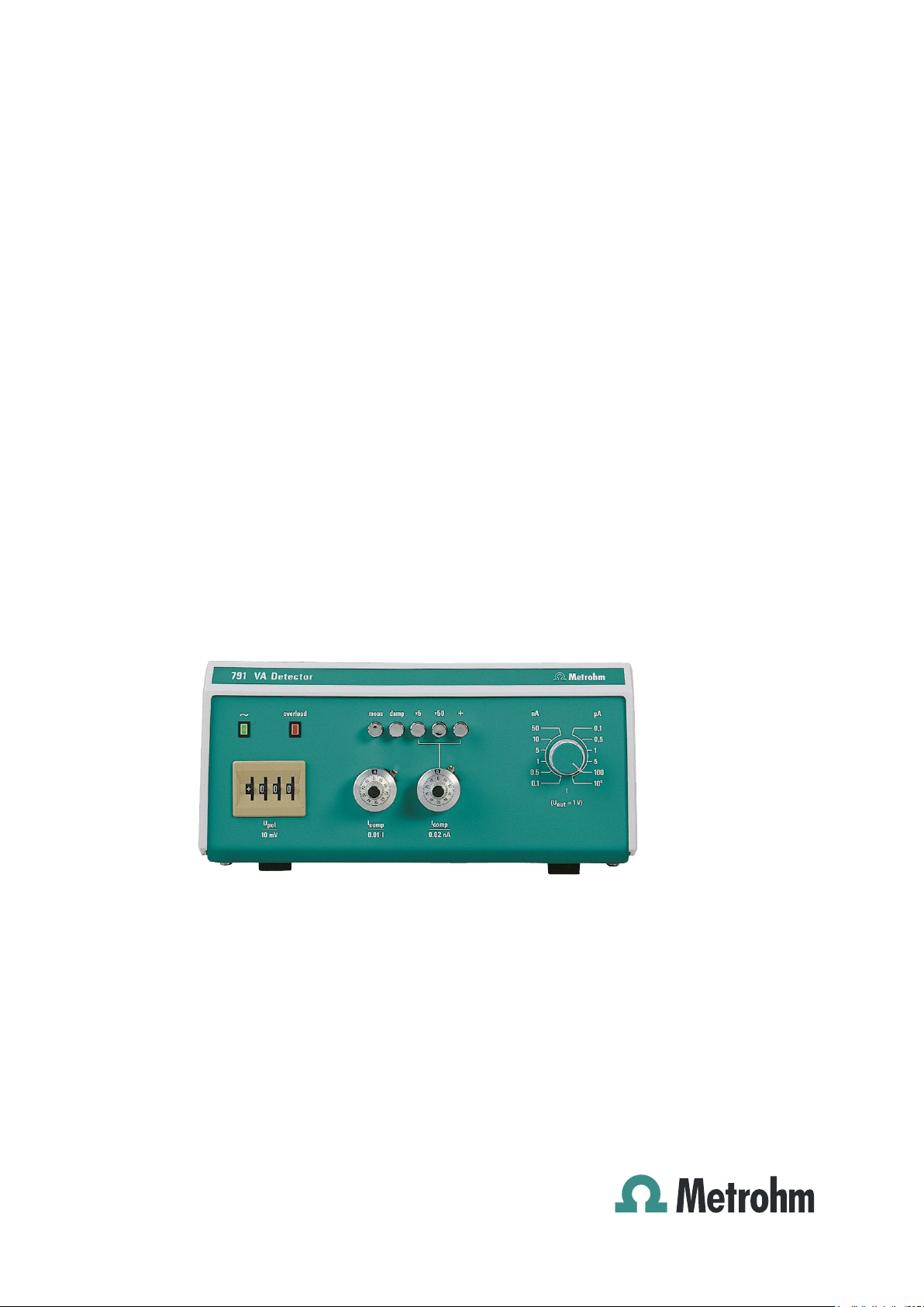
Fig. 1: Front of the 791 VA Detector ............................................................................. 2
: Rear of the 791 VA Detector.............................................................................. 3
Fig. 2
Fig. 3
: Setting the mains voltage.................................................................................. 9
Fig. 4
: Connection 656 – 791 .....................................................................................10
Fig. 5
: ELCD cell assembly ........................................................................................12
Fig. 6
: Connection of ELCD cell at detector block..................................................... 13
Fig. 7
: Connection of ELCD cell at 791 VA Detector.................................................. 13
Fig. 8
: Selection of polarization voltage .....................................................................17
Fig. 9
: Circuit of 6.2813.020 Dummy Cell................................................................... 34
791 VA Detector
II
Page 7

1.1 Instrument description
1 Introduction
1.1 Instrument description
The 791 VA Detector allows the use of electrochemical/amperometric
detection in IC and HPLC; various working electrodes are available depending on the application. It can be used in series with another detector (e.g. 732 Conductivity detector) or simply as a «stand alone» detector.
The self-ventilating measuring cell functions according to the timeproved wall-jet principle with three-electrode technology. A silver/silver
chloride system is used as the reference electrode and a solid gold pin
as the auxiliary electrode. The carbon paste electrode and the silver
electrode have proved to be the best working electrodes; but other
electrode materials such as glassy carbon, gold, platinum and impregnated graphite are available for special applications.
The 791 VA Detector is available in the two following versions:
• 2.791.0010 VA Detector for HPLC
The measuring cell is built into the 656 Electro chemical detector.
• 2.791.0020 VA Detector for IC
The measuring cell belongs to the accessories and
is built into the 733 IC Separation Center.
791 VA Detector
1
Page 8
1 Introduction
1.2 Parts and controls
13
2 4567
VA Detector791
I
comp
0.02 nA
+
~
+
overload meas
015
U
pol
10 mV
I
0.01
comp
x5damp
.
I
nAx50
50
10
0,5
0,1
5
1
Met rohm
I
(U = 1 V)
out
µ
0,1
0,5
1
5
100
10
A
4
11 89
Fig. 1
Mains pilot lamp
1
Lit up when instrument switched
: Front of the 791 VA Detector
10
7 Commutator
Changing the polarity of I
on
2 Overload display 8 Adjusting knob
Setting the current measuring sensitivity
3 Commutator
Changeover Stand-by/Measure
4 Commutator
Switching on/off damping
5 Commutator
Switching on/off multiplication of
by a factor of 5
I
comp
9 Potentiometer
Setting the absolute compensation
current I
comp
10 Potentiometer
Setting the relative compensation
current I
comp
11 Digital switch
Setting the polarization voltage
comp
6 Commutator
Switching on/off multiplication of
by a factor of 50
I
comp
791 VA Detector
2
Page 9
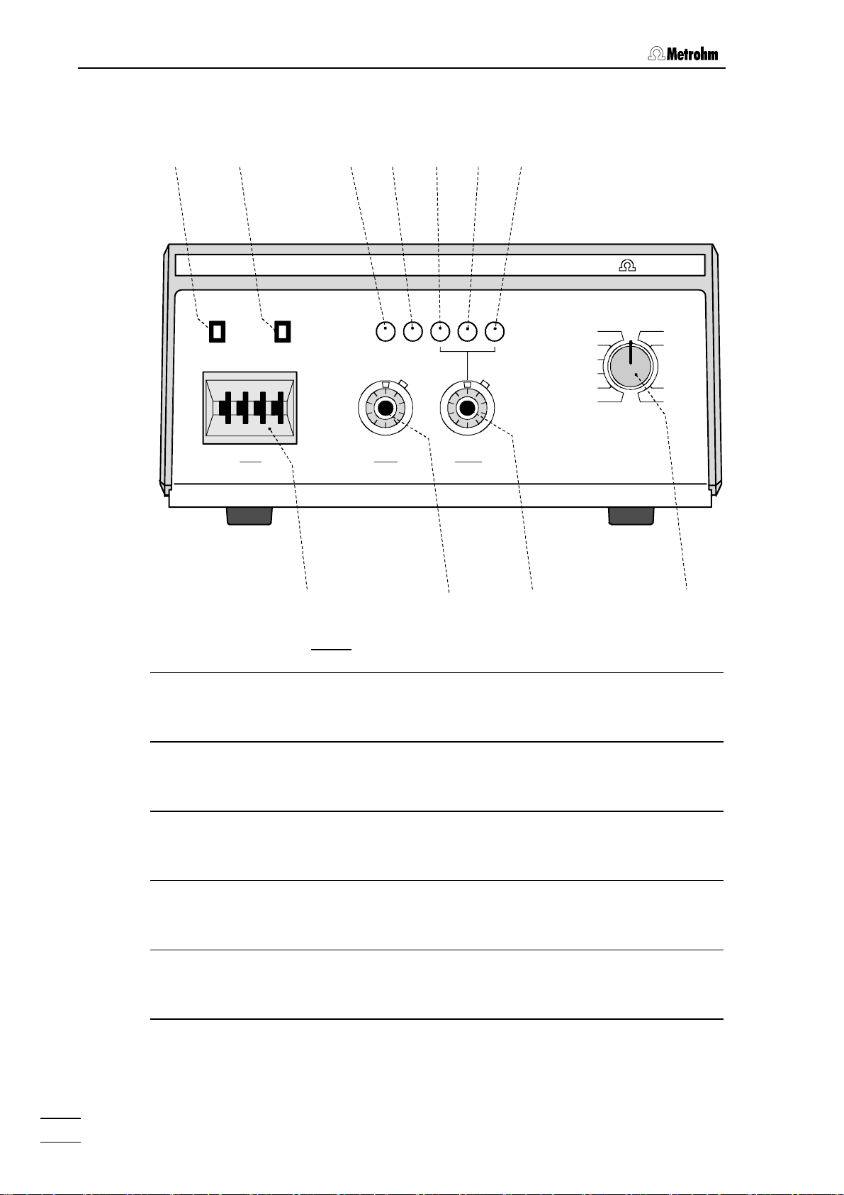
1.2 Parts and controls
12
151413
Type 1.791.0010
f = 50-60 Hz Made by Metrohm Herisau Switzerland
S = 5 VA
Fuse
100-240 V: 1A(T)
WARNING - Fire Hazard -
For continued protection replace only
with the same type and rating of fuse
pilot
voltage
Nr.
16 17 18 19
AE RE WE shield
output 0...1 V
com 0...10 mV
Fuse holder
12
changing the fuses, see section 2.2
26 20
25
Fig. 2
: Rear of the 791 VA Detector
20 Selector
Selection of polarity for analog
output
13 Mains voltage indicator 21 Selector
Selection of full-scale deflection for
analog output
14 Earthing socket 22 Analog output (live)
15 Connection AE
23 Analog output (common)
Connection of auxiliary electrode
16 Serial number 24 Pilot voltage
Input for external voltage input for
potentiostat control
17 Connection RE
Connection of reference electrode
25 Mains switch
To switch instrument on/off:
I = ON 0 = OFF
21222324
18 Connection WE
26 Mains connection plug
Connection of working electrode
19 Connection for protective screen
791 VA Detector
Mains connection, see section 2.2
3
Page 10

1 Introduction
1.3 Information on the Instructions for Use
Please read through these Instructions for Use carefully before you put
the 791 VA Detector into operation. The Instructions for Use contain
information and warnings to which the user must pay attention in order
to assure safe operation of the instrument.
1.3.1 Organization
These 8.791.1013 Instructions for Use for the 791 VA Detector provide a comprehensive overview of the installation, startup procedure,
operation, fault rectification and technical specifications of this instrument. The Instructions for Use are organized as follows:
Section 1 Introduction
General description of instrument, parts and controls
and safety notes
Section 2 Installation
Installation of accessories, connection to IC system
Section 3 Operation
Electrodes, operating element functions,
startup
Section 4 Maintenance – Faults
Maintenance, fault rectification
Section 6 Appendix
Technical data, standard equipment, options, warranty,
declarations of conformity, index
To find the required information on the instruments you will find it an
advantage to use either the Table of contents or the Index at the
back.
791 VA Detector
4
Page 11
1.3 Information on the Instructions for Use
1.3.2 Notation and pictograms
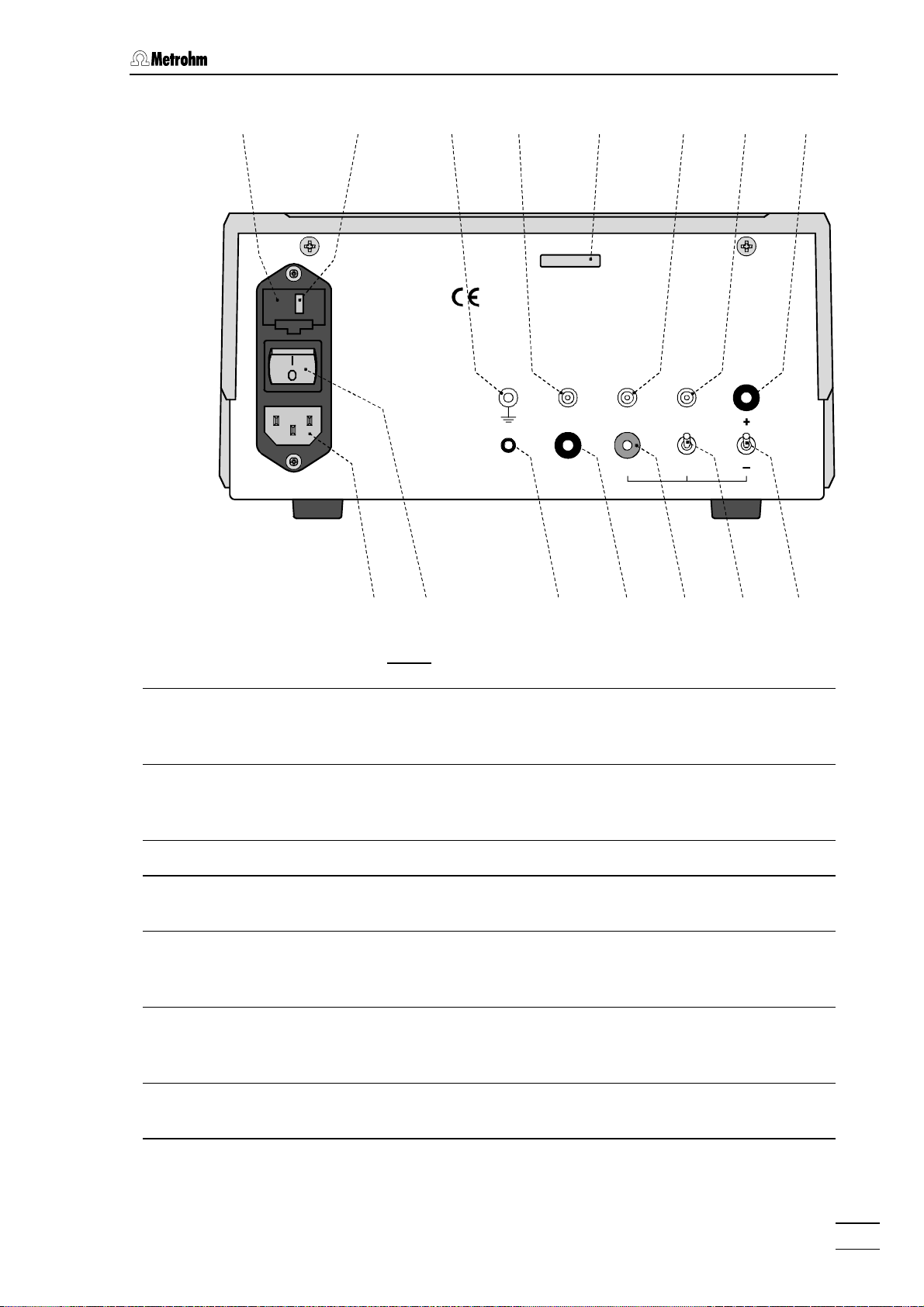
The following notations and pictograms (symbols) are used in these Instructions for Use:
15 Part or control of 791
Hazard
This symbol draws attention to a
possible danger to life or of injury if
the associated directions are not
followed correctly.
Warning
This symbol draws attention to
possible damage to instruments or
instrument parts if the associated
directions are not followed correctly.
Caution
This symbol marks important
information. First read the associated directions before you continue.
Comment
This symbol marks additional
information and tips.
791 VA Detector
5
Page 12
1 Introduction
1.4 Safety notes
1.4.1 Electrical safety
While electrical safety in the handling of the 791 VA Detector is assured
in the context of the specifications IEC 1010-1 (protection class 1, degree of protection IP40), the following points should be noted:
• Mains connection
Setting of the mains voltage, checking the mains fuse and the
mains connection must be effected in accordance with the instruc-
tions in section 2.2.
• Opening the 791 VA Detector
If the 791 VA Detector is connected to the power supply, the instrument must not be opened nor must parts be removed from it, otherwise there is a danger of coming into contact with components which
are live. Hence, always disconnect the instrument from all voltage
sources before you open it and ensure that the mains cable is
disconnected from mains connection 26 !
• Protection against static charges
Electronic components are sensitive to static charging and can be
destroyed by discharges. Before you touch any of the components
inside the 791 VA Detector, you should earth yourself and any tools
you are using by touching an earthed object (e.g. housing of the
instrument or a radiator) to eliminate any static charges which exist.
1.4.2 General precautionary rules
• Handling of solvents
Check all lines periodically for possible leaks. Follow the relevant
instructions regarding the handling of flammable and/or toxic solvents
and their disposal.
791 VA Detector
6
Page 13

2.1 Setting up the instrument
2 Installation
2.1 Setting up the instrument
2.1.1 Packaging
The 791 VA Detector is supplied together with the separately packed
accessories in special packagings containing shock-absorbing foam
linings designed to provide excellent protection. The instrument itself is
packed in an evacuated polyethylene bag to prevent the ingress of
dust. Please store all these special packagings as only they assure
transport of the instrument free from damage.
2.1.2 Check
After receipt, immediately check whether the shipment is complete and
has arrived without damage (compare with delivery note and list of
accessories in section 5.2). In the case of transport damage, see
instructions in section 5.4.1 "Warranty".
2.1.3 Location
Position the instrument in the laboratory at a location convenient for
operation, free from vibrations and protected against a corrosive
atmosphere and contamination by chemicals.
2.1.4 Arrangement of the instruments
The 791 VA Detector can be placed on the 732 IC Detector or the 733
IC Separation Center.
791 VA Detector
7
Page 14
2 Installation
2.2 Mains connection
Follow the instructions below for connecting to the power supply. If
the instrument is operated with a mains voltage set wrongly and/or
wrong mains fuse, there is a danger of fire!
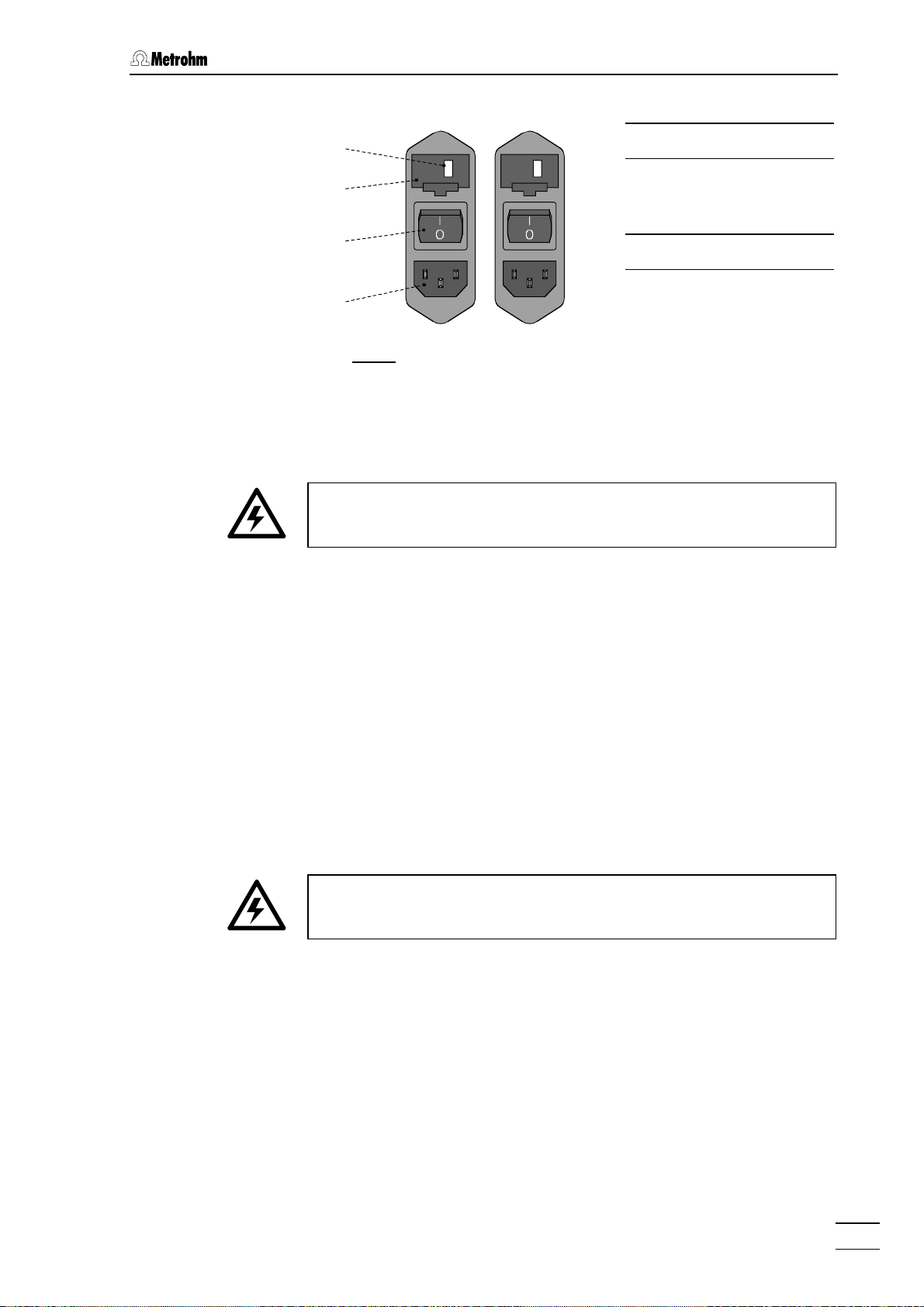
2.2.1 Setting the mains voltage
Before switching on the 791 VA Detector for the first time, check that the
mains voltage set on the instrument (see Fig. 3) matches the local
mains voltage. If this is not
on the instrument as follows:
the case, you must reset the mains voltage
1 Disconnect mains cable
Disconnect mains cable from mains connection plug 26 of the
791 VA Detector.
2 Remove fuse holder
Using a screwdriver, loosen fuse holder 12 and take out completely.
3 Change mains voltage
Completely remove voltage selection insert 13 by hand, rotate it
through 180° and reinsert it. The required mains voltage (115 or
230 V) must now be visible from the front.
4 Check fuses
Carefully take both fuses out of fuse holder 12 and check their
specifications:
100…240 V 1 A (slow-blow) Metrohm-No. U.600.0016
5 Insert fuses
Change both fuses if necessary and reinsert in fuse holder 12.
6 Install fuse holder
Push fuse holder 12 back into the opening of 791 VA Detector
by hand until it clicks into place properly.
791 VA Detector
8
Page 15
2.2 Mains connection
100 – 120 V220 – 240 V
13
12
230
115
12 Fuse holder
13 Voltage selection
insert with display
of voltage
25
26
Fig. 3
: Setting the mains voltage
2.2.2 Fuses
Two fuses 1 A/slow-blow for 100…240 V are installed in the fuse holder
12 of the 791 VA Detector as standard.
Ensure that the instrument is never put into operation with fuses of
another type, otherwise there is danger of fire!
For checking or changing fuses, proceed as described in section 2.2.1.
2.2.3 Mains cable and mains connection
Mains cable
The instrument is supplied with one of three mains cables
25 Mains switch
26 Mains connection
plug
• 6.2122.020 with plug SEV 12 (Switzerland, …)
• 6.2122.040 with plug CEE(7), VII (Germany, …)
• 6.2133.070 with plug NEMA 5-15 (USA, …)
which are three-cored and fitted with a plug with an earthing pin. If a different plug has to be fitted, the yellow/green lead (IEC standard) must
be connected to protective earth (protection class 1).
Any break in the earthing inside or outside the instrument can make it
a hazard!
Mains connection
Plug the mains cable into mains connection plug 26 of the 791 VA Detector (see Fig. 3).
2.2.4 Switching the instrument on/off
The 791 VA Detector is switched on and off using mains switch 25.
When the instrument is switched on lamp 1 lights up.
791 VA Detector
9
Page 16
2 Installation
2.3 656 Electrochemical detector
2.3.1 Installation and startup
Inserting the detector cell in shield housing, fitting the electrodes and
startup of the 656 Electrochemical detector (order number 2.656.0020)
are described in detail in the 656 Instructions for use.
2.3.2 Connection to 791 VA Detector
The electrodes used in the detector cell are each connected to the corresponding connection of the 791 VA Detector with a 6.2120.020 Electrode cable as shown in Fig. 4. In addition the two earthing sockets are
connected with a 6.2106.020 Cable.
6.2120.0 20 6.2106.0 20
656
AE WE RE
Fig. 4
AE RE WE
: Connection 656 – 791
791
791 VA Detector
10
Page 17

2.4 6.5303.030 ELCD cell for IC
2.4 6.5303.030 ELCD cell for IC
2.4.1 Assembling the ELCD cell
The reference electrode and working electrode must be inserted in the
6.5303.030 ELCD Cell supplied with the 2.791.0020 VA Detector. The
cell is then screwed into the detector block built into the 733 IC Separation Center. Proceed as follows (see Fig. 5 and Fig. 6):
1 Insert reference electrode
Reference electrode 39 (6.0727.000, details see section 3.2.2)
included in the supply is already filled with c(KCl) = 3 mol/L and
protected with a cap. It is assembled as follows (see Fig. 5):
• Screw off the cap of electrolyte storage vessel 41 of reference
electrode 39. Normally PTFE gasket 31 remains in the cap
and can be left there.
• Insert one of the supplied PTFE gaskets 31 into the corre-
sponding opening of cell body 32 and screw reference electrode 39 into this opening.
2 Insert working electrode
Working electrode 28 is not supplied with the 791 VA Detector
and must be ordered separately. Details about the working
electrodes and information about pretreatment (e.g. polishing)
can be found in section 3.2.1. A working electrode is assembled
as follows (see Fig. 5):
• Insert working electrode 28 in screw nipple 29.
• Push one of the supplied PTFE gaskets 31 sufficiently far
along the working electrode from below.
• Carefully insert working electrode 28 into the corresponding
opening of cell body 32 from above and press it in until it
clearly clicks into position.
• Push screw nipple 29 downwards and screw it in.
3 Connect ELCD cell to the detector block
The ELCD cell is screwed onto the 1.733.0X10 Detector block
mounted inside the 733 Separation Center. Proceed as follows
(see Fig. 5 and Fig. 6):
• Screw cell body 32 onto detector block 42 with the help of
the two red knurled screws 43.
• Push one of the supplied PTFE gaskets 31 over screw nipple
33 and screw this into the corresponding opening of cell
body 32.
• Place a screw nipple 36 and a PTFE gasket 35 on the outlet
end of the outlet capillary 37 permanently connected to detector block 42.
• Insert outlet capillary 37 with screw nipple 36 in place into
screw nipple 33 and press in outlet capillary 37 until it
reaches the stop.
791 VA Detector
11
Page 18

2 Installation
• Screw nipple 36 onto screw nipple 33 to fix outlet capillary 37
is position.
4 Discharge
• Pull outlet capillary 38 which is already mounted on cell body
32 through one of the openings in the rear panel of the 733 IC
Separation Center so that it emerges outside the instrument.
• Insert outlet capillary 38 in a sufficiently large waste container
and fix it in position.
4139 3140
2731
28
29
30
31
35
36
38
: ELCD cell assembly
Fig. 5
27
ELCD cell (6.5303.030) 35 PTFE gasket (6.2704.020)
28 Working electrode 36 Screw nipple (4.420.2580)
29 Screw nipple (6.2730.000) 37 PEEK outlet capillary from
1.733.0X10 Detector block
32
31
33
34
35
36
37
30 Sealing ring (E.301.0028) 38 PTFE outlet capillary (6.1803.000)
31 PTFE gasket (6.2704.010) 39 Reference electrode (6.0727.000)
32 Cell body 40 Ag/AgCl Reference system
33 Screw nipple (6.2731.030) 41 Electrolyte vessel
34 Sealing ring (E.301.0004)
791 VA Detector
12
Page 19

2.4 6.5303.030 ELCD cell for IC
42
37
43
28
32
39
43
38
: Connection of ELCD cell at detector block
Fig. 6
Working electrode 39 Reference electrode
28
32 Cell body 42 Detector block (1.733.0X10)
37 PEEK outlet capillary from
1.733.0X10 Detector block
38 PTFE outlet capillary
(6.1803.000)
2.4.2 Connection to 791 VA Detector
The ELCD cell electrodes are each connected to the corresponding
connection of the 791 VA Detector with a 6.2120.020 Electrode cable as
shown in Fig. 7. The 791 VA Detector must be switched off and in the
"stand-by" position when this is taking place.
(6.0727.000)
43 Knurled screw (V.900.4006)
791 VA Detector
6.2120.020
RE
Fig. 7
6.2120.020
6.2120.020
WE
AE
AE
AE RE WE
: Connection of ELCD cell at 791 VA Detector
791
13
Page 20

2 Installation
2.5 Analog output connections
The 791 VA Detector has two analog output sockets: 22 (live) and 23
(common) for connecting a chart recorder of a different data recording
instrument. The full-scale deflection range for the analog output (1 V or
10 mV) can be set with switch 21; the polarity can be changed with
switch 20 (see section 3.3).
The 6.2115.010 Cable can be used for connecting recorders with banana plug connections; the 6.2115.060 Cable can be used for connecting data recording instruments with terminals.
791 VA Detector
14
Page 21

3.1 Electrochemical detection
3 Operation
3.1 Electrochemical detection
3.1.1 Classes of substances which can be determined
A precondition for the use of electrochemical detection is that the substances to be determined are electrochemically active on the particular
working electrode used, i.e. they can easily be oxidized or reduced. The
electrical current produced by this reaction is proportional to the concentration of the substance throughout a wide range. It is measured,
amplified and recorded as a function of time by the 791 VA Detector in
the form of a chromatogram.
The following table provides an overview of the classes of substances
and ions which can be detected by oxidation or reduction. The approximate polarization voltage obtained when an Ag/AgCl/c(KCl) =
3 mol/L reference electrode is used is given; this depends to a large extent on the working electrode and eluents used (see section 3.2). The
limits of detection which can be achieved are in the lower ppb range.
Structural formula Classes/substances Polarization voltage
R
OH
R
NH
2
5
3
N
H
Aromatic hydroxy compounds
Antioxidants
Catecholes
Flavones
Halogenated phenols
Hydroxybiphenyls
Hydroxycumarines
Methoxyphenols
Oestrogens
Phenols
Tocopherols
Aromatic amines
Anilines
Benzidines
Sulfonamides
Indols
Indolyl-3-compounds
5-Hydroxy-indols
+800 … +1200 mV
+ 800 mV
+ 1000 mV
+ 1200 mV
+ 800 mV
+ 1000 mV
+ 800 mV
+ 1000 mV
+ 1200 mV
+ 800 mV
+ 1000 mV
+ 600 mV
+ 1200 mV
+ 1000 mV
+ 800 mV
791 VA Detector
S
N
H
Phenothiazines + 1000 mV
15
Page 22

3 Operation
Structural formula Classes/substances Polarization voltage
RSH
O
O
R NO
R
R
Mercaptans + 800 mV
Miscellaneous
Ascorbic acid
Carotenes
Purine derivatives
Vitamin A
Quinones
Vitamin K
1
+ 800 mV
+ 800 mV
+ 1000 mV
+ 1000 mV
– 700 mV
2
Nitro compounds
Nitrophenol
Nitroglycerin
Isosorbidedinitrate
Inorganic anions
Nitrite
Sulfide
Thiosulfate
Chlorite
Bromide
Iodide
Cyanide
Thiosulfate
Thiocyanate
– 700 mV
– 800 mV
– 800 mV
+ 1100 mV
+ 0 mV
+ 1100 mV
+ 1100 mV
+ 150 mV
+ 150 mV
+ 0 mV
+ 1100 mV
+ 1200 mV
3.1.2 Influence on detector signal
The sensitivity of detection, i.e. the height of the detector signal and the
background current in the electrochemical detection depend on the following parameters:
• polarization voltage
• temperature (approx. 1.5 %/°C)
• flow rate of eluent
• surface of electrodes and interior of cell
• Eluent composition
(pH value, type and concentration of conductive salt,
type and concentration of organic components, etc.)
Each change of one of these parameters will change the background
current and the detector signal. Therefore, every parameter change
needs a stabilization time to elapse; this is normally a few minutes for
791 VA Detector
16
Page 23

3.1 Electrochemical detection
current ranges > 5 nA. Please pay particular consideration to this on
changing the eluent or the sample solution: the "same" eluent may have
a different background current because eluents are never exactly the
same (ionic strength, pH value, etc.!).
3.1.3 Selection of polarization voltage
The hydrodynamic voltammograms show the voltage limit from the
point where a substance is oxidized or reduced. This voltage limit is
generally higher than the voltage predicted by thermodynamics because of inhibitions of the electrode reaction. Increasing voltage values
give rise to increasing currents up to a maximum value, the diffusioncontrolled limiting current.
In Fig. 8 for example, analytes a, b, and c are detected at voltage U
whereas at voltage U
, component a is detected selectively. Therefore
1
the polarization voltage to be set has to be optimized for sensitivity on
one hand and selectivity on the other.
The polarization voltage to be set also depends on the type and condition of the working electrode (see section 3.5) as well as on the eluent.
The latter could be illustrated by Fig. 8, saying that the curves are from
one single analyte taken in 3 eluents with different pH values.
I
Diffusioncontrolled
limiting
current
abc
U
1
Fig. 8
: Selection of polarization voltage
U
2
Background
current
U
pol
;
2
3.1.4 Procedure for unknown substances
The hydrodynamic current/voltage curve of an analyte with unknown
electrochemical characteristics is recorded as follows:
• Short circuit the system, i.e. connect the injector directly (without
separating column) to the electrochemical detector.
• Set current range of 791 VA Detector to 100 … 500 nA.
• Set polarization voltage of 791 VA Detector to +1200 mV.
• Inject analyte (20 … 100 ng).
791 VA Detector
17
Page 24

3 Operation
If no signal is observed, change the pH value of the eluent (a protonated or deprotonated substance may be oxidized more easily). Generally, a higher polarization voltage has to be applied with lower pH values (approx. 50 … 100 mV per pH unit).
st
• 1
experiment with eluent of pH ≈ 6
nd
• 2
experiment with eluent of pH ≈ 3
If there is still no signal, the analyte is "inactive", i.e. not suitable for electrochemical detection.
As soon as a signal is observed, decrease the polarization voltage in
steps of 100 mV: a hydrodynamic current/voltage curve results.
For detection, select the lowest polarization voltage U
good signal is still observed.
3.1.5 Practical information about ELCD
In principle the electrochemical detector can be connected to all HPLC
and IC systems. In order to carry out work successfully, particularly in
trace-level quantities, all components such as pump, dampening system, injector, separating column, capillaries, couplings, etc. must be in
perfect condition. In electrochemical detection it is possible that interferences may occur which, for example, are not observed with UV or
conductivity detection. These can often be traced back to contaminants
from the water supply system (e.g. Fe(II) ions), contaminants from the
separating column (e.g. organic residues) or variations in pressure
caused by leaking connections.
Particular attention must be given to the following points:
Cleanliness
The general demands placed on trace analysis work also apply here.
Each possible source of corrosion of steel components must be
avoided as Fe(II) ions may interfere. The eluent should also not contain
any complexing agents.
at which a
pol
Pulsation
The noise of the detector signal depends on the pressure variation inside the cell and on the back-pressure (max. 1 bar), which is determined by the length of outlet capillary 38 (i.d. 0.3 mm). The use of a
pulsation dampener (e.g. Metrohm 6.2620.150 Pulsation dampener) for
dampening such pulsations has proved itself in practice and is also
adequate if only single-piston pumps are used.
Eluent
Most of the solvents normally used in HPLC and IC can be used to prepare eluents. The conductivity which is necessary for detection is
achieved by the addition of a conductive salt. Concentrations of 1…10
g/L are normally adequate for this purpose, this results in a conductivity
of approx. 1…10 mS/cm. Sulfates, nitrates, phosphates, acetic acid,
791 VA Detector
18
Page 25

3.1 Electrochemical detection
sulfuric acid, perchloric acid, lithium perchlorate, etc. can be used for
this. Chlorides and hydroxycarboxylic acids should not be used; some
reagents which form ion pairs can be used.
Solvent gradients can be used in less sensitive ranges (current range >
100 nA). The eluent is degassed as usual by vacuum or passing a
stream of helium through it.
Stationary phase
In principle all reversed-phase and ion exchanger materials can be
used. New columns must be purged well and for a sufficiently long time
for any contaminants which may be present to be washed out. This
"equlibration phase" of a column may take more than 24 hours in the
most sensitive areas.
Sample solution
Whenever possible, the eluent used should also be used as the solvent
for the sample in order to minimize interference owing to changing surroundings (as small a front peak as possible). Very small amounts of
the active substance should be used, in general < 100 ng.
791 VA Detector
19
Page 26

3 Operation
3.2 Electrodes
3.2.1 Working electrodes
The quality of a working electrode WE can be assessed in terms of the
following criteria:
• Background current (after adequate running-in time):
this should be small and constant
• Interference level ("noise"):
this should be low
• Response characteristics:
after switching on, the low background current should be
quickly reached
It should nevertheless be borne in mind that increases in both background current and noise levels are often due to other causes than a
poor-quality working electrode (for example, contamination of the HPLC
system, malfunction of the pulsation dampener, etc.). Generally speaking, both background current and noise levels tend to increase with
higher polarization voltages, and are usually greater in eluents based
on mixed solvents than in those composed of purely aqueous solutions.
Glassy carbon electrode GCE
Ordering designation 6.0805.010
Sensor material Glassy carbon, GC
Chemical resistance good resistance to acetonitrile, methanol, wa-
ter, etc.
Voltage range (–800) … 0 … +1200 mV (pH < 7)
Regeneration
Sprinkle a little aluminium oxide powder (Al
on the polishing cloth (ordering number of both these accessories: 6.2802.000) and moisten with distilled water. Hold the electrode vertically and polish with a circular motion for about
20…60 s, exerting only light pressure. Rinse with distilled water
and clean with dry cloth. A glassy carbon electrode should always
be polished for a short while immediately before being fitted to
the detector cell.
, grain size 0.3 µm)
2O3
Ultra-Trace graphite electrode
Ordering designations 6.1204.100 Ultra-Trace graphite tip
+ 6.2103.110 Contact pin
Sensor material Graphite (turnover is three times larger than in
GC-electrode; does not need tamping)
Chemical resistance good resistance to acetonitrile, methanol, wa-
ter, etc.
Voltage range –800 … 0 … +1200 mV (pH < 7)
Regeneration
With 6.2827.000 Trimming tool (see electrode data sheet).
791 VA Detector
20
Page 27

3.2 Electrodes
Carbon paste electrode CPE
Ordering designation 6.0807.000
Sensor material paste composed of spectroscopic grade car-
bon powder and paraffin
Chemical resistance good resistance to aqueous solutions; limited
resistance only to water/acetonitrile and water/methanol mixtures
Voltage range (–200) … 0 … +1200 mV (pH < 7)
Regeneration
The sensor surface of the CPE is more vulnerable to both mechanical damage and chemical attack than that of the GCE, it is
more easily regenerated: often it suffices merely to rub the tip of
the electrode backwards and forwards a few times against the
surface of a sheet of ordinary, smooth paper, or alternatively the
upper layer of carbon paste can be renewed (see below) and
then polished in this manner.
Filling
Carefully remove the old carbon paste from the approximately
2.5 mm deep cavity with a suitable sharp instrument. Take care
not to damage the platinum contact wire at the bottom of the cavity. Using a small spatula, fill bit by bit with the fresh 6.2801.020
carbon paste and tamp well down using the 6.2826.000 stopper.
The cavity should be filled over the brim with paste. Now rub off
the excess paste by continuous circular motion against a sheet of
paper with a hard, smooth, non-porous surface; the circular motion plus the light pressure will polish the surface of the paste,
which must be smooth and shiny when the operation is finished.
There should be no cracks in the peripheral zone where the paste
is up against the plastic material of the electrode shaft.
Metal electrodes
Ordering designations 6.1204.120 Pt tip
6.1204.130 Ag tip
6.1204.140 Au tip
+ 6.2103.110 Contact pin
Chemical resistance good resistance to acetonitrile, methanol, wa-
ter, etc.
Voltage range Pt: (–1200) … 0 … +200 mV (pH < 7)
Ag: (–800) … 0 … +400 mV (pH > 7)
Au: (–400) … 0 … +1200 mV (pH < 7)
Regeneration
Sprinkle a little aluminium oxide powder (Al
on the polishing cloth (ordering number of both these accessories: 6.2802.000) and moisten with distilled water. Hold the electrode vertically and polish with a circular motion for about
20…60 s, exerting only light pressure. Rinse with distilled water
and clean with dry cloth. A metal electrode should always be polished for a short while immediately before being fitted to the detector cell.
, grain size 0.3 µm)
2O3
791 VA Detector
21
Page 28

3 Operation
Amalgamated electrode
"Home-made" amalgamated electrodes are prepared as follows:
Base material 6.1204.140 Au tip
Preparation Put a few drops of Hg on the front side of the
electrode and leave it for a few minutes. Knock
off excess Hg and rinse electrode with distilled
water.
Chemical resistance good resistance to acetonitrile, methanol, water
Voltage range –1200 … 0 mV
Regeneration polish electrode with aluminium oxide and re-
amalgamate
3.2.2 Reference electrode
The reference system of the 6.0727.000 Reference electrode (RE) is
Ag/AgCl/c(KCl) = 3 mol /L (see Fig. 5). The electrolyte vessel 41 can be
refilled. The KCl solution has to be renewed every 1…2 months.
Ordering designations for KCl solutions: 6.2308.020 (250 mL)
3.2.3 Auxiliary electrode
A gold electrode is built-in in the detector cell as an auxiliary electrode.
6.2313.000 (1 L)
791 VA Detector
22
Page 29

3.3 Operating element functions
3.3 Operating element functions
Mains switch
The 791 VA Detector is switched on and off using mains switch
25 on the rear of the instrument (see Fig. 2):
I Instrument switched on
0 Instrument switched off
~
After the instrument has been switched on, the mains pilot lamp 1
lights up to show that the instrument is ready for use.
Relative compensation current
rel. is set using the
comp
I
comp
The relative compensation current I
potentiometer 10 (see Fig. 1). The value set is related to the
setting of the adjusting knob 8 (current I).
.
I0.01
Setting range –500 (red) … +500 (white) × 0.01 x I
Resolution 0.01 x I per scale division
Absolute compensation current
The absolute compensation current I
potentiometer 9 (see Fig. 1). The value set is not related to the
setting of the adjusting knob 8 (current I).
abs. is set using the
comp
I
comp
0.02 nA
Setting range
direct 0 … 1000 × 0.02 nA = 20 nA
with commutator 5 5 × 20 nA = 100 nA
with commutator 6 50 × 20 nA = 1000 nA
Resolution
direct 0.02 nA per scale division
with commutator 5 0.10 nA per scale division
with commutator 6 1.00 nA per scale division
The polarity of the absolute compensation current is set separately with commutator 7.
Changeover Stand-by/Measure
meas
For this changeover commutator 3 (see Fig. 1) is used.
Button depressed
Measuring position, i.e. measuring cell connected.
Button not depressed
Stand-by position, i.e. measuring cell disconnected.
791 VA Detector
23
Page 30

3 Operation
Damping
damp
The damping is switched on and off using commutator 4 (see
Fig. 1).
Button depressed
Signal damped for all ranges set on adjusting knob 8 in order to suppress interference (spurious signals).
Button not depressed
No signal damping (exception: the most sensitive range,
0.1 nA, is always damped to some extent).
x50
x5
Multiplication of I
For this changeover commutator 5 (see Fig. 1) is used.
Button depressed
abs. by a factor of 5
comp
Multiplication of the absolute compensation current by a
factor of 5.
Button not depressed
No multiplication of the absolute compensation current.
Multiplication of I
abs. by a factor of 50
comp
For this changeover commutator 6 (see Fig. 1) is used.
Button depressed
Multiplication of the absolute compensation current by a
factor of 50.
Button not depressed
No multiplication of the absolute compensation current.
+
Polarity of I
For this changeover commutator 7 (see Fig. 1) is used.
Button depressed
comp
abs.
All current values set on the potentiometer 9 have a positive
sign.
Button not depressed
All current values set on the potentiometer 9 have a negative sign.
791 VA Detector
24
Page 31

3.3 Operating element functions
overload
Overload display
If the electronic current measuring circuit is overloaded, the red
light 2 is lit up (see Fig. 1).
Remedies
Select a less sensitive current range with adjusting knob 8
or compensate current with potentiometer 9 and/or 10 (for
further measures see section 4.3).
Polarization voltage
is set using the digital switch 11 (see
pol
+
015
U
10 mV
The detection voltage U
Fig. 1).
Setting range –1990 … 0 … +1990 mV
pol
Resolution 10 mV
Current measuring sensitivity
nA
50
10
5
1
0,5 100
0,1
(U
out
I
= 1 V)
µ
A
The sensitivity of current measurement is set using adjusting
0,1
knob 8 (see Fig. 1). The set range applies to the full-scale
0,5
deflection of the analog signal at sockets 22 and 23 (1 V or
1
5
10 mV depending on the setting of switch 21).
4
10
Setting ranges 0.1, 0.5, 1, 5, 10, 50 nA
0.1, 0.5, 1, 5, 100, 10'000 µA
Polarity of analog output
The polarity (+ or –) of the analog output signal is set using
switch 20 (see Fig. 2).
Full-scale deflection of analog output
0...1 V
0...10 mV
The full-scale deflection (1 V or 10 mV) of the analog output
signal is set using switch 21 (see Fig. 2).
791 VA Detector
25
Page 32

3 Operation
3.4 Startup
3.4.1 Preparing the ELCD cell
The ELCD cell must be correctly connected to the HPLC or IC system
before it is filled (see section 2.3 and section 2.4). Then proceed as follows:
1 Fill reference electrode (only if necessary)
Reference electrode 39 (6.0727.000) is supplied in a filled
condition. However, the KCl electrolyte solution must be replaced every 1 to 2 months. Proceed as follows:
• Screw Ag/AgCl reference system 40 out of electrolyte vessel
41 (see Fig. 5).
• Fill electrolyte vessel 41 to the brim with c(KCl) = 3 mol/L.
• Screw Ag/AgCl reference system 40 back onto electrolyte
vessel 41. Take care that no air bubbles are found in the electrolyte vessel (to check: hold reference electrode against the
light).
2 Connect reference electrode
• Insert reference electrode 39 into cell body 32 (see Fig. 5).
• Connect reference electrode 39 to connection 17 of the 791
VA Detector with 6.2120.020 Cable (see Fig. 7).
3 Connect auxiliary electrode
• Connect the auxiliary electrode in cell body 32 to connection
15 of the 791 VA Detector 791 with 6.2120.020 Cable (see
Fig. 7).
4 Prepare working electrode
• Prepare and polish working electrode 28 according to section
3.2.1.
• Insert working electrode 28 into cell body 32 (see Fig. 5).
• Do not
at this point.
5 Start pump
• Switch on delivery drive of HPLC or IC pump.
connect working electrode 28 to the 791 VA Detector
791 VA Detector
26
Page 33

3.4 Startup
3.4.2 Zero balancing and equilibration phase
Before the first measurement is made the working electrode must be allowed to equilibrate and the chart recorder or data recording instrument
must be zero-balanced. Proceed as follows:
1 Chart recorder settings
If a chart recorder is used to record the analog signals then
proceed as follows (the working electrode must not
nected to the 791 VA Detector):
• Switch on 791 VA Detector.
• Set commutator 3 on the 791 VA Detector to "Stand-by".
• Set the required polarity (+ or –) with switch 20; use switch
21 to set the required voltage range for the analog output on
the 791 VA Detector (1 V or 10 mV).
• Set potentiometer 9 on the 791 VA Detector to 0.
• Use knob 8 on the 791 VA Detector to set the current sensitiv-
ity to 0.5 µA.
• Switch on recorder.
• Set the voltage measuring range on the recorder to the same
setting as on the 791 VA Detector (1 V or 10 mV).
• Use potentiometer 10 on the 791 VA Detector to adjust the
zero point of the recorder.
be con-
2 Settings with a data recording program
If a PC recording and evaluation program is used for recording
the analog signals then proceed as follows (the working electrode must not
be connected to the 791 VA Detector):
• Switch on 791 VA Detector.
• Set commutator 3 on the 791 VA Detector to "Stand-by".
• Set the required polarity (+ or –) with switch 20; use switch
21 to set the required voltage range for the analog output on
the 791 VA Detector (1 V or 10 mV).
• Set potentiometers 9 and 10 on the 791 VA Detector to 0.
• Use knob 8 on the 791 VA Detector to set the current sensitiv-
ity to 0.5 µA.
• Switch on the data recording program on the PC and start
recording data.
• If required, use potentiometer 10 on the 791 VA Detector to
adjust the zero point (so that the mV display on the PC shows
0).
791 VA Detector
27
Page 34

3 Operation
3 Overload test
For this test the working electrode must not be connected to the
791 VA Detector:
• Set the polarization voltage on the 791 VA Detector to the
required value for the following determinations with digital
switch 11.
• Set commutator 3 on the 791 VA Detector to "meas". Over-
load display 2 must light up briefly and then go out again.
• If overload display 2 remains lit up for a longer period of time
this indicates that there is a faulty electrical contact between
the reference electrode and the auxiliary electrode. Eliminate
the cause (e.g. air in the system or in the reference electrode,
blocked diaphragm, faulty cable connection) and repeat the
test.
• If the overload test is OK, set commutator 3 on the 791 VA
Detector back to "Stand-by".
4 Equilibrating the working electrode
• Connect working electrode 28 to connection 18 of the 791 VA
Detector with the 6.2120.020 Cable.
• Set commutator 3 on the 791 VA Detector to "meas".
• Observe equilibration curve: the curve should flatten out
noticeably within a relative short time (10…20 min), otherwise
the working electrode must be repolished or refilled.
• In current measuring ranges > 5 nA a constant base current
is usually achieved with one hour. At higher sensitivities the
working electrode should be equilibrated overnight.
5 Zero balancing the base current
(only for recorders)
• Set the current measuring sensitivity on the 791 VA Detector
with knob 8 to the required value.
• Use potentiometer 9 on the 791 VA Detector to adjust the
base current to the zero point of the recorder. If the setting
range of potentiometer 9 is not sufficient then it can be extended by using commutator 5 (× 5) or 6 (× 50).
791 VA Detector
28
Page 35

3.4 Startup
3.4.3 Measuring procedure
In order to be able to carry out measurements it is essential that the
working electrode has achieved a stable base current (see section
3.4.2). If the value of the base current regains its original value after the
determination then as many determinations as required can be carried
out. Attention should be given to the following points:
1 Carrying out the determination
• Inject the sample solution into the HPLC or IC system.
• Record and evaluate the current curve.
2 Allow ELCD system to run overnight
• If the ELCD system is to be used again on the following day
then the 791 VA Detector should not be switched off overnight. The working electrode is constantly under the polarization current and is quickly ready for new measurements.
• The HPLC or IC pump is set to a minimal flow rate and runs
overnight. This means that the base current is stabilized after
only a few minutes.
3 Switching off the ELCD system
• Set commutator 3 on the 791 VA Detector to "Stand-by".
• Unplug working electrode 28.
• Switch off the 791 VA Detector.
791 VA Detector
29
Page 36

3 Operation
791 VA Detector
30
Page 37

4.1 Maintenance and servicing
4 Maintenance – Malfunctions
4.1 Maintenance and servicing
Care
The 791 VA Detector requires proper care and attention. Excessive contamination of the instrument could possibly lead to malfunctions and a
shorter service life of the inherently rugged mechanical and electronic
parts.
Spilled chemicals and solvents should be wiped up immediately. It is
especially important to protect the plug connections at the rear of the
instrument (particular the mains plug) against contamination.
Although constructional measures have been designed to virtually
eliminate such a situation, should corrosive media penetrate the
interior of the instrument the mains plug of the 791 VA Detector must
be immediately disconnected to prevent extensive damage to the
instrument electronics. Inform Metrohm service if your instrument have
been damaged in such a way.
The instrument must not be opened by untrained personnel. Please
comply with the safety notes in section 1.4.1.
Maintenance by Metrohm service
Maintenance of the 791 VA Detector is best done as part of an annual
service performed by specialists from the Metrohm company. If work is
frequently performed with caustic and corrosive chemicals, it may be
necessary to shorten the interval between servicing.
The Metrohm service department is always willing to offer expert advice
on the maintenance and servicing of all Metrohm instruments.
4.2 Shutdown
If the ELCD cell is shut down for a considerable length of time, the entire HPLC or IC system (without
rinsed free from salt with methanol/water (1:4) to avoid crystallization
of eluent salts with the corresponding subsequent damage.
column and suppressor) must be
791 VA Detector
31
Page 38

4 Maintenance – Malfunctions
4.3 Malfunctions and their rectification
Malfunction Cause Rectification
No signal • VA Detector is in "stand-by"
mode.
• VA Detector switched off or
disconnected from mains
voltage.
• Recorder switched off or
disconnected from mains
voltage.
• Recorder disconnected from
VA Detector.
• Electrodes disconnected.
• Broken interconnecting
cables.
VA Detector
shows "overload"
• Current range set exceeded
by too high a concentration of
substance.
• The VA Detector is either
incorrectly balanced or not
balanced at all.
• Reference electrode discon-
nected.
• Auxiliary electrode discon-
nected.
• Polarization voltage badly
adjusted.
• Press "meas" button on VA
Detector.
• Connect VA Detector and
switch on.
• Connect recorder and switch
on.
• Connect recorder to the VA
Detector.
• Connect electrodes.
• Use new interconnecting
cables.
• Wait or set a higher current
range at the VA Detector.
• Balance the recording instru-
ment and VA Detector correctly.
• Connect reference electrode.
• Connect auxiliary electrode.
• Adjust polarization voltage
correctly.
Excessively high
background current
Baseline unstable
• Polarization voltage too high.
• Eluent contaminated.
• Eluent contaminated by Fe(II)
ions from rusty steel parts
(traces only suffice!)
• Highly retarded or enriched
components from the separating column.
• Pressure fluctuations due to
poor seals, blocked filters or
capillaries, defective pump,
etc.
• Eluent contaminated by Fe(II)
ions from rusty steel parts
(traces only suffice!).
• Defective reference electrode.
• Polarization voltage should
generally not be set higher than
1200 mV.
• Prepare fresh eluent using only
the purest (AR grad) chemicals.
• Check entire HPLC or IC system
for rust; check resistance of all
materials to the reagents in use.
• Rinse the column well with
eluent or regenerate it, use new
column if necessary.
• Check HPLC or IC system for
these faults.
• Check entire HPLC or IC system
for rust; check resistance of all
materials to the reagents in use.
• Replace reference electrode.
791 VA Detector
32
Page 39

4.3 Malfunctions and their rectification
Malfunction Cause Rectification
Noise level too high
Spikes on baseline
• Inadequate pulsation
damping.
• Electrostatic screening
defective.
• Background current too high.
• Eluent outlet tubing under
electrostatic influence.
• Defective working electrode.
• Defective 791 VA Detector.
• Air in detector cell.
• Air entering detector cell.
• If a CPE working electrode is
in use, the carbon paste is not
in good condition.
• Use pulsation dampener.
• Check screening, if necessary
connect steel column and/or its
outlet to socket 14 of the VA
Detector by means of a cable.
• Check screening, if necessary
connect steel column and/or its
outlet to socket 14 of the VA
Detector by means of a cable.
• Immerse eluent outlet tubing
completely in spent solution in
waste recipient or renew PTFE
tubing if necessary.
• Replace working electrode.
• Check 791 VA Detector using
the dummy cell (see section
4.1.4)
• Unscrew working electrode and
deaerate detector cell.
• Degas eluent or subject it to
appropriate treatment.
• Refill CPE and ensure paste is
well tamped down.
Isolated spikes on
baseline
Substance turnover
too low or nonexistent
Substance turnover
falls off
Front peak too high • Environment altered by
• Electrostatic discharges from
operating personnel on the
apparatus.
• Mains interference.
• Electromagnetic interference
from environment.
• Polarization voltage too low.
• Active surface of working
electrode blocked by substances.
• Active surface of working
electrode blocked by substances.
• Quantity of substance too
great.
sample solution.
• Eluent contaminated by Fe(II)
ions from rusty steel parts
(traces only suffice!).
• Such discharges cannot be
completely avoided, but are not
usually too troublesome at
normal (i.e. not too dry) atmospheric humidity.
• Connect all instruments to the
power supply via a suitable filter
(e.g. Metrohm 615 Mains Distributor).
• Change "environment".
• Increase polarization voltage.
• Polish working electrode or
renew paste in CPE.
• Polish working electrode or
renew paste in CPE.
• The sample quantity should be
less than 100 ng per injection to
avoid blocking of the electrode
surface.
• Whenever possible, use eluent
as solvent for the sample solution.
• Check entire HPLC or IC system
for rust; check resistance of all
materials to the reagents in use.
791 VA Detector
33
Page 40

4 Maintenance – Malfunctions
4.4 Instrument test with the dummy cell
The correct functioning of the 791 VA Detector can be checked with the
included 6.2813.020 Dummy cell. Several simple checks can be carried
out with this extremely simplified electrical simulation of a detector cell.
Fig. 9 shows the construction of the dummy cell. The checks described
below can be carried out with the recording instrument which is connected (chart recorder, integrator, PC data recording program) or, for
precise measurements, with a voltmeter which is connected to analog
outputs 22 and 23. The dummy cell is connected to the corresponding
cable instead of the electrode. Each test can be carried out separately.
The settings of any operating elements which are not mentioned are irrelevant.
AE
10 M
Ω
1%
Ω
10
1 µF
RE
Fig. 9
: Circuit of 6.2813.020 Dummy Cell
WE
4.4.1 Check of "meas" and "damp" commutators and of current amplifier offset
1 Set digital switch 11 U
to +1000 mV.
pol
+
100
2 Set adjusting knob 8 to 0.1 µA.
3 Set potentiometer 9 I
791 VA Detector
34
abs. to 0.
comp
50
10
5
1
0,5 100
0,1
0.02 nA
I
comp
0,1
0,5
1
5
4
10
Page 41

4.4 Instrument test with the dummy cell
4 Set all commutators 3 … 7 to "off" position
(non-depressed position).
5 Set selector 20 on the rear panel to +.
6 Set selector 21 on the rear panel to 0…10 mV.
7 Bring recorder of voltmeter to 0 using potenti-
ometer 10 I
rel.. The value shown on the
comp
knob scale must not vary from 0 by more than
120 scale divisions.
8 Depress commutator 3 "meas": The recorder or
voltmeter should read –10 mV.
9 Depress commutator 4 "damp" and wait until
recorder of voltmeter have attained a stable
position.
0...1 V
0...10 mV
I
comp
meas
damp
.
I0.01
10 Set commutator 3 "meas" to "off" position: The
time constant τ to be measured, i.e. the time
which has to elapse until 63.2 % of full-scale
deflection is reached, should have a value of
app. 3 s (consider τ of recorder or voltmeter).
4.4.2 Check output voltage
1 Set digital switch 11 U
2 Set adjusting knob 8 to 0.1 µA.
to 0 mV.
pol
meas
+
000
50
10
5
1
0,5 100
0,1
0,1
0,5
1
5
4
10
791 VA Detector
3 Set commutators 4 … 7 to "off" position (non-
depressed position).
35
Page 42

4 Maintenance – Malfunctions
4 Set selector 20 on the rear panel to –.
5 Set selector 21 on the rear panel to 0…1 V.
6 Set recorder sensitivity to 1000 mV.
7 Set commutator 3 "meas" to "on" position
(depressed position).
8 Set potentiometer 9 I
abs. to 0.
comp
9 Bring recorder of voltmeter to 0 using potenti-
ometer 10 I
10 Alter the settings of digital switch 11 U
comp
rel..
pol
in
steps of 100 mV and 10 mV: The settings
shown on the digital switch should be reproduced on the recorder or voltmeter within a
tolerance of <12.5 mV and <1.25 mV respectively.
0...1 V
0...10 mV
meas
I
comp
0.02 nA
+
I
comp
.
I0.01
140
11 Set digital switch 11 U
to – and alter the
pol
settings in steps of 100 mV and 10 mV: The
settings shown on the digital switch should be
reproduced on the recorder or voltmeter within
a tolerance of <12.5 mV and <1.25 mV respectively.
4.4.3 Check of current compensation
1 Set digital switch 11 U
2 Set adjusting knob 8 to 0.1 µA.
to 0 mV.
pol
250
+
000
50
10
5
1
0,5 100
0,1
0,1
0,5
1
5
4
10
791 VA Detector
36
Page 43

4.4 Instrument test with the dummy cell
3 Set selector 20 on the rear panel to –.
4 Set selector 21 on the rear panel to 0…1 V.
5 Set commutator 3 "meas" to "on" position
(depressed position).
6 Set potentiometer 9 I
abs. to 0.
comp
7 Bring recorder of voltmeter to 0 using potenti-
ometer 10 I
8 If potentiometer 10 I
comp
rel..
rel. is now moved
comp
counterclockwise by 100 divisions (= 1 turn)
then this should correspond to 1000 mV on the
recording instrument or voltmeter.
0...10 mV
0.02 nA
0...1 V
meas
I
comp
I
comp
I
comp
.
I0.01
.
I0.01
9 If potentiometer 9 I
abs. is now moved
comp
clockwise by 100 divisions (= 1 turn) then this
should correspond to the following values on
the recording instrument or voltmeter:
direct: +20 mV
×5 button 5 depressed: +100 mV
×50 button 6 depressed: +1000 mV
10 Set commutator 7 (+) to "on" position
(depressed position).
11 Similarly check the functioning of potentiometer
10 I
rel. according to items 7…9.
comp
I
comp
0.02 nA
I
comp
+
.
I0.01
791 VA Detector
37
Page 44

4 Maintenance – Malfunctions
4.4.4 Check of current and voltage overload
1 Set digital switch 11 U
to +10 mV or
pol
–10 mV.
2 Set adjusting knob 8 to 50 nA.
3 Set selector 20 on the rear panel to –.
4 Set selector 21 on the rear panel to 0…1 V.
5 Set potentiometer 9 I
abs. to 0.
comp
+
001
50
10
5
1
0,5 100
0,1
0...1 V
0...10 mV
I
comp
0.02 nA
0,1
0,5
1
5
4
10
6 Set commutators 3 … 7 to "off" position (non-
depressed position).
7 Bring recorder of voltmeter to 0 using potenti-
ometer 10 I
comp
rel..
8 Set commutator 6 "×50" to "on" position
(depressed position).
9 Turn potentiometer 9 I
abs. clockwise until
comp
overload display 2 lights up: The voltage at the
recorder output should be app. 10.5…12 V.
Without digital voltmeter, read the value on the
scale of potentiometer 9: The value should be
between 500 and 620 scale divisions.
10 Reset potentiometer 9 I
abs. to 0: The
comp
overload display 2 extinguishes.
I
comp
.
I0.01
x50
I
comp
0.02 nA
0.02 nA
791 VA Detector
38
I
comp
Page 45

4.4 Instrument test with the dummy cell
11 Set commutator 3 "meas" to "on" position
(depressed position).
12 Unplug dummy cell at "AE": the overload
display 2 lights up.
4.4.5 Check sensitivity knob 8
1 Unplug dummy cell.
2 Set adjusting knob 8 to 50 nA.
3 Set commutators 3 … 7 to "off" position (non-
depressed position).
meas
50
10
5
1
0,5 100
0,1
0,1
0,5
1
5
4
10
4 Set potentiometer 9 I
abs. to 0.
comp
5 Set selector 21 on the rear panel to 0…1 V.
6 Bring recorder of voltmeter to 0 using potenti-
ometer 10 I
rel. (set line recorder first to mid-
comp
scale).
7 Turn adjusting knob 8 through all positions and
check the deviation from zero after a waiting
time of app. 5 s. Deviation should be < ±1 V.
I
comp
0.02 nA
0...1 V
0...10 mV
I
comp
.
50
10
5
1
0,5 100
0,1
I0.01
0,1
0,5
1
5
4
10
791 VA Detector
39
Page 46

4 Maintenance – Malfunctions
4.4.6 Check of noise from current amplifier
1 Connect dummy cell.
2 Set digital switch 11 U
to 0 V.
pol
3 Set adjusting knob 8 to 1 nA.
4 Set commutator 3 "meas" to "on" position
(depressed position).
5 Set commutators 4 … 7 to "odd" position
(non-depressed position).
6 Set selector 21 on the rear panel to 0…1 V.
+
000
50
10
5
1
0,5 100
0,1
meas
0...1 V
0...10 mV
0,1
0,5
1
5
4
10
7 Allow the recording instrument to record for a
longer period of time (first adjust chart recorder
to middle of the scale). Typical deflections
caused by noise are about 10 mVpp or less (the
656 housing must be earthed).
791 VA Detector
40
Page 47

5.1 Technical data
5 Appendix
5.1 Technical data
Measuring instrument
Measuring technique Direct current amperometry
Polarization voltage U
Current measurement Measurement: direct, not integrated
Damping Switchable
Compensation current I
absolute
Range: –1990 … 0 … +1990 mV
pol
Resolution: 10 mV
Deviation: ± 1 % ± 1 mV
Sensitivity: 0.1, 0.5, 1, 5, 10, 50 nA
0.1, 0.5, 1, 5, 100, 10'000 μA
Deviation: ± 15 % for 0.1 nA … 5 nA
± 1.5 % for 10 nA … 0.1 μA
± 1.0 % for 0.5 … 100 μA
± 4.0 % for 10'000 μA
Time constants: ≈ 5.0 s for < 0.1 nA
≈ 0.6 s for 0.1 ... 0.5 nA
≈ 0.3 s for 0.5 ... 1 nA
≈ 0.1 s for 1 ... 5 nA
Time constant: 1.7 s
comp
Basic range: –20 … 0 … +20 nA
Resolution: 0.02 nA
Multiplication: 5 ×, 50 ×
relative
Potentiostat Input resistance: 1012 Ω (typ. value)
Analog output
Signal U = f ( I )
Polarity Switchable
Max. load < 5 mA
Input resistance at
connected instrument
Range: –5.00 … 0 … +5.00· I
Resolution: 0.01· I
Input current: < 5 pA (typ. value)
Zero-point drift: 20 μV/K (typ. value)
Output voltage: ± 10 V
Output current: ≤ 10 mA
1 V or 10 mV DC for the full current range I
> 2 kΩ
791 VA Detector
41
Page 48

5 Appendix
Mains connection
Voltage 115 V: 100...120 V ± 10 %
230 V: 220...240 V ± 10 %
Switchable with voltage selector insert in the fuse
holder (see section 2.2.1)
Frequency 50...60 Hz
Power consumption 5 VA
Fuse 5 mm dia., 20 mm length
100…240 V: 1 A (slow-blow)
Safety specifications
Construction/testing According to IEC 1010 / EN 61010 / UL 3101-1,
protection class 1, degree of protection IP40
Safety directions The Instructions for Use include information and
warnings which must be heeded by the user to
assure safe operation of the instrument.
Electromagnetic compatibility (EMC)
Emitted interference Standards met:
EN55011 (class B), EN55022 (class B),
EN 50081-1/2
Immunity to interference Standards met:
IEC801-2/IEC1000-4-2 (class 3), IEC801-4/
IEC1000-4-4 (class 3), IEC1000-3/EN61000-3,
IEC1000-4-11/EN61000-4-11
Ambient temperature
Nominal operating range +5…+40°C
(at 20…80 % atmospheric humidity)
Storage, transport –40…+70°C
Housing
Material of cover Polyurethane rigid foam (PUR) with fire protection
for fire class UL94VO, CFC-free
Material of base Steel, enameled
Dimensions
Width 260 mm
Height 129 mm
Depth 366 mm
Weight 3.6 kg (with accessories)
791 VA Detector
42
Page 49

5.2 Standard equipment
59
5.2 Standard equipment
Subject to changes !
All dimensions are given in mm.
5.2.1 2.791.0010 VA Detector for HPLC
The 2.791.0010 VA Detector includes the following parts:
Quant. Order No. Description
1 6.2105.030 Cable
Connection cable 791 VA Detector
(analog output) – recorder
1 6.2122.0X0 Mains cable
to customer's specifications:
Cable socket Cable connector
Type IEC 320/C 13 Type SEV 12 (CH…)............................... 6.2122.020
Type IEC 320/C 13 Type CEE (7), VII (D…) .......................... 6.2122.040
Type CEE (22), V Type NEMA 5-15 (USA…)...................... 6.2122.070
1 6.2813.020 Dummy Cell
Electrical simulation of the ELCD cell for
testing and checking functions
1 8.791.1013 Instruction for Use (English)
for 791 VA Detector
1.2 m
791 VA Detector
43
Page 50

5 Appendix
67
∅
∅
59
5.2.2 2.791.0020 VA Detector for IC
The 2.791.0020 VA Detector includes the following parts:
Quant. Order No. Description
1 6.0727.000 Reference electrode
Mini reference electrode for ELCD
cell with Ag/AgCl/c(KCl) = 3 mol/L
reference system;
including cap
3 6.2120.020 Electrode cable
Electrode cable with mini socket
for connection pins 2 mm and mini
plug type F
1 6.2122.0X0 Mains cable
to customer's specifications:
Cable socket Cable connector
Type IEC 320/C 13 Type SEV 12 (CH…) ...............................6.2122.020
Type IEC 320/C 13 Type CEE (7), VII (D…) ...........................6.2122.040
Type CEE (22), V Type NEMA 5-15 (USA…).......................6.2122.070
1 6.2617.000 Tool for PTFE gasket
To remove 6.2704.010 and 6.2704.020
PTFE gaskets
∅ 18
83
2 m
4
67
4 6.2704.010 PTFE gasket
Gasket for reference electrode,
working electrode and eluent inlet
3 6.2704.020 PTFE gasket
Gasket for eluent inlet
1 6.2813.020 Dummy Cell
Electrical simulation of the ELCD cell for
testing and checking functions
1 6.5303.030 ELCD cell
1 8.791.1013 Instruction for Use (English)
for 791 VA Detector
4.3
∅ 12
6
4.5
791 VA Detector
44
Page 51

5.3 Optional accessories
∅
∅
M3
∅
5.3 Optional accessories
Order No. Description
6.0805.010 Mini Glassy Carbon electrode
Diameter of active zone: 2.8 mm.
6.0807.000 Mini Carbon paste electrode
Diameter of active zone: 3 mm.
6.1204.XXX Electrode tips for working electrode
Together with 6.2103.110 Contact pin forms the working
electrode. The following electrode tips are available:
Order No. Disk material Shaft material
6.1204.100 Ultra Trace Graphite PVC
6.1204.120 Pt PEEK
6.1204.130 Ag PEEK
6.1204.140 Au PEEK
Disk diameter: 2.0 +0 / –0.05 mm
6.2103.110 Contact pin
Together with 6.1204.1X0 Electrode tip forms the
working electrode.
7
45
7
45
52.5
21.3
7
6.2801.020 Carbon paste
Carbon paste for 6.0807.000 Mini carbon
paste electrode
6.2826.000 Filling tool
Filling tool for 6.0807.000 Mini carbon paste
electrode
20
83
791 VA Detector
45
Page 52

5 Appendix
5.4 Warranty and conformity
5.4.1 Warranty
The warranty on our products is limited to defects that are traceable to
material, construction or manufacturing error which occur within 12
months from the day of delivery. In this case, the defects will be rectified in our workshops free of charge. Transport costs are to be paid by
the customer.
For day and night operation, the warranty is limited to 6 months.
Glass breakage in the case of electrodes or other parts is not covered
by the warranty. Checks which are not a result of material or manufacturing faults are also charged during the warranty period. For parts of
outside manufacture insofar as these constitute an appreciable part of
our instrument, the warranty stipulations of the manufacturer in question
apply.
With the regard to the guarantee of accuracy, the technical specifications in the instruction manual are authoritative.
Concerning defects in material, construction or design as well as the
absence of guaranteed features, the orderer has no rights or claims except those mentioned above.
If damage of the packaging is evident on receipt of a consignment or if
the goods show signs of transport damage after unpacking, the carrier
must be informed immediately and a written damage report demanded.
lack of an official damage report releases Metrohm from any liability to
pay compensation.
If any instruments and parts have to be returned, the original packaging
should be used if at all possible. This applies above all to instruments,
electrodes, burette cylinders and PTFE pistons. Before embedment in
wood shavings or similar material, the parts must be packed in a dustproof package (for instruments, use of a plastic bag is imperative). If
open assemblies are enclosed in the scope of delivery that are sensitive to electromagnetic voltages (e.g. data interfaces etc.) these must
be returned in the associated original protective packaging (e.g. conductive protective bag). (Exception: assemblies with built-in voltage
source belong in a non-conductive protective packaging). For damage
which arises as a result of non-compliance with these instructions, no
warranty responsibility whatsoever will be accepted by Metrohm.
791 VA Detector
46
Page 53

5.4 Warranty and conformity
5.4.2 EU Declaration of conformity
EU Declaration of Conformity
The METROHM AG company, Herisau, Switzerland hereby certifies, that the instrument:
791 VA Detector
meets the requirements of EC Directives 89/336/EEC and 73/23/EEC.
Source of the specifications:
EN 50081-1/2 Electromagnetic compatibility, basic specification;
Emitted Interference
EN 61010 Safety requirements for electrical laboratory measurement
and control equipment
Description of the instrument:
High-sensitivity current measuring instrument for electrochemical detection
in HPLC and IC.
Herisau, September 11, 1998
Dr. J. Frank Ch. Buchmann
Development Manager Production and
Quality Assurance Manager
791 VA Detector
47
Page 54

5 Appendix
5.4.3 Certificate of conformity and system validation
Certificate of Conformity and System Validation
This is to certify the conformity to the standard specifications for electrical appliances and accessories, as well as to the standard specifications for security and
to system validation issued by the manufacturing company.
Name of commodity: 791 VA Detector
Name of manufacturer: Metrohm Ltd., Herisau, Switzerland
Principal technical information: Voltages: 100…120, 220…240 V
Frequency: 50…60 Hz
This Metrohm instrument has been built and has undergone final type testing
according to the standards:
IEC801-2/IEC1000-4-2 (class 3), IEC801-4/IEC1000-4-4 (class 3),
IEC1000-3/EN 61000-3, IEC1000-4-11/EN 61000-4-11, EN55011 (class B),
EN55022 (class B), EN50081-1/2
— Electromagnetic compatibility
IEC1010, EN61010, UL3101-1 — Security specifications
The technical specifications are documented in the instruction manual.
Metrohm Ltd. is holder of the SQS-certificate of the quality system ISO 9001 for
quality assurance in design/development, production, installation and servicing.
Herisau, September 11, 1998
Dr. J. Frank Ch. Buchmann
Development Manager Production and
Quality Assurance Manager
791 VA Detector
48
Page 55

5.5 Index
5.5 Index
A
Absolute compensation current........... 23
Adjusting knob 8
Figure...................................................2
Operation.......................................... 25
Test ................................................... 39
Ag electrode ......................................... 21
Amalgamated electrode....................... 22
Ambient temperature............................ 42
Analog output 22
Connection ....................................... 14
Figure...................................................3
Technical data .................................. 41
Analog output 23
Connection ....................................... 14
Figure...................................................3
Technical data .................................. 41
Appendix............................................... 41
Arrangement of the instruments..............7
Au electrode .................................... 21,22
Auxiliary electrode
Connect to 791................................. 26
Notes ................................................ 22
B
Back pressure ...................................... 18
Background current ........................ 20,32
Base current ......................................... 29
Baseline unstable ................................. 32
C
Cable (6.2105.030)............................... 43
Cable (6.2106.020)............................... 10
Cable (6.2115.010)............................... 14
Cable (6.2115.060)............................... 14
Cable (6.2120.020)..................... 10,26,44
Carbon paste........................................ 45
Carbon paste electrode .................. 21,45
Care ...................................................... 31
Caution ....................................................5
Cell body 32
Assembly .......................................... 11
Figure........................................... 12,13
Certificate of conformity
and system validation ...................... 48
Changeover Stand-by/Measure........... 23
Chart recorder ................................. 14,27
Check ......................................................7
Classes of substances ......................... 15
Classes of substances
which can be determined................. 15
Cleanliness ........................................... 18
Comment.................................................5
Commutator 3
Figure...................................................2
Operation.......................................... 23
Test ................................................... 35
Commutator 4
Figure...................................................2
Operation.......................................... 24
Test ................................................... 35
Commutator 5
Figure ..................................................2
Operation ..........................................24
Commutator 6
Figure ..................................................2
Operation ..........................................24
Commutator 7
Figure ..................................................2
Operation ..........................................24
Compensation current ..........................41
Conformity.............................................47
Connection 15 "AE"
Connecting the
auxiliary electrode .............................13
Figure ..................................................3
Connection 17 "RE"
Connecting the
reference electrode ......................13,26
Figure ..................................................3
Connection 18 "WE"
Connecting the working electrode.... 13
Connection of working electrode......28
Figure ..................................................3
Connection 19
Figure ..................................................3
Connection 656 – 791...........................10
Contact pin (6.2103.110) ......................45
Current amplifier offset.......................... 34
Current compensation ..........................36
Current measurement ........................... 41
Current measuring sensitivity................25
D
Damping...........................................24,41
Data recording instrument ....................27
Declaration of conformity ......................47
Degree of protection ..........................6,42
Detector block 42
ELCD cell assembly ..........................11
Figure ................................................13
Detector signal ...................................... 16
Diffusion-controlled limiting current ...... 17
Digital switch 11
Figure ..................................................2
Dimensions ...........................................42
Disposal...................................................6
Dummy cell .................................34,43,44
E
Earthing ................................................6,9
Earthing socket 14
Figure ..................................................3
ELCD cell 27
Assembly...........................................11
Connection to VA Detector 791 ........13
Figure ................................................12
Ordering designation ........................44
Startup...............................................26
Electrical safety .......................................6
Electrochemical detection.....................15
Electrochemical Detector 656
Connection to VA Detector 791 ........10
Installation ......................................... 10
Electrode cable (6.2120.020) ...............10
Electrodes ............................................. 20
Electrolyte vessel 41
Assembly...........................................11
Figure ................................................ 12
Filling reference electrode ................26
Electromagnetic compatibility ..............42
Eluent ....................................................18
EMC.......................................................42
Emitted interference..............................42
Equilibration phase ............................... 27
EU Declaration of conformity................ 47
F
Filling tool .............................................. 45
Front ........................................................ 2
Front peak ............................................. 33
Full-scale deflection .............................. 25
Fuse holder 12
Change fuses...................................... 8
Figure ............................................... 3,9
Fuses............................................... 8,9,42
G
General precautionary rules ...................6
Glassy Carbon electrode .................20,45
Gold electrode ......................................45
H
Handling of solvents ...............................6
Hazard..................................................... 5
Housing.................................................42
I
Immunity to interference .......................42
Information on the
Instructions for Use............................. 4
Installation ............................................... 7
Instructions for Use (8.791.1013) ...........4
Instrument description ............................ 1
Instrument test ......................................34
Interference level................................... 20
Introduction ............................................. 1
K
Knurled screw 43
ELCD cell assembly.......................... 11
Figure ................................................ 13
L
Leaks.......................................................6
Location .................................................. 7
791 VA Detector
49
Page 56

5 Appendix
M
Mains cable................................... 9,43,44
Mains connection.................................. 42
Procedure ........................................... 8
Safety notes ........................................6
Mains connection plug 26
Figure ............................................... 3,9
Mains connection................................ 9
Mains frequency ................................... 42
Mains pilot lamp 1
Figure .................................................. 2
Ready for use display ....................9,23
Mains switch 25
Figure ............................................... 3,9
Operation ..........................................23
Switching the instrument on/off .......... 9
Mains voltage........................................42
Setting ................................................. 8
Mains voltage indicator 13
Figure .................................................. 3
Maintenance .........................................31
Malfunctions.......................................... 32
Measuring procedure ...........................29
Measuring technique ............................ 41
Metal electrodes ..............................21,45
Metrohm service ...................................31
Multiplication ......................................... 24
N
No signal ............................................... 32
Noise ........................................... 18,20,40
Noise level............................................. 33
Notation................................................... 5
O
Opening the 791 VA Detector................. 6
Operating element functions ................23
Operation ..............................................15
Optional accessories ............................ 45
Organization............................................ 4
Outlet capillary 37
Assembly ..........................................11
Figure ........................................... 12,13
Outlet capillary 38
Assembly ..........................................12
Figure ........................................... 12,13
Output voltage ......................................35
Overload........................................... 32,38
Overload display 2
Figure .................................................. 2
Operation ..........................................25
Overload test......................................... 28
P
Packaging ............................................... 7
Parts and controls...................................2
Pictograms.............................................. 5
Pilot voltage 24
Figure .................................................. 3
Platinum electrode ................................ 45
Polarity.........................................24,25,41
Polarization voltage................ 15,17,25,41
Potentiometer 9
Figure.................................................. 2
Operation .......................................... 23
Potentiometer 10
Figure.................................................. 2
Operation .......................................... 23
Potentiostat ........................................... 41
Power consumption.............................. 42
Practical information about ELCD ........ 18
Precautionary rules ................................. 6
Protection class ..............................6,9,42
Protective earth....................................... 9
Pt electrode........................................... 21
PTFE gasket 31
Assembly ..........................................11
Figure................................................ 12
Ordering designation........................ 44
PTFE gasket 35
Assembly ..........................................11
Figure................................................ 12
Ordering designation........................ 44
Pulsation ............................................... 18
Pulsation dampener ............................. 18
R
Rear......................................................... 3
Reference electrode 39
Assembly ..........................................11
Connect to 791 ................................. 26
Figure........................................... 12,13
Filling................................................. 26
Notes................................................. 22
Ordering designation........................ 44
Reference system 40
Figure................................................ 12
Filling reference electrode ................ 26
Relative compensation current............. 23
Response characteristics ..................... 20
Rinsing the IC system........................... 31
S
Safety directions ...................................42
Safety notes ............................................ 6
Safety specifications............................. 42
Sample solution .................................... 19
Screw nipple 29
Assembly ..........................................11
Figure................................................ 12
Screw nipple 33
Assembly ..........................................11
Figure................................................ 12
Screw nipple 36
Assembly ..........................................11
Figure................................................ 12
Sealing ring 30
Figure................................................ 12
Sealing ring 34
Figure................................................ 12
Selection of polarization voltage .......... 17
Selector 20
Figure.................................................. 3
Selector 21
Figure.................................................. 3
Serial number 16
Figure.................................................. 3
Service .................................................. 31
Servicing ............................................... 31
Setting the mains voltage....................... 9
Setting up the instrument ....................... 7
Settings
Mains voltage ..................................... 8
Shutdown.............................................. 31
Silver electrode ..................................... 45
Spikes ................................................... 33
Spilled chemicals ................................. 31
Standard equipment............................. 43
Startup .................................................. 26
Static charges......................................... 6
Stationary phase................................... 19
Storage ................................................. 42
Substance turnover .............................. 33
Switch 20
Operation.......................................... 25
Switchover ........................................ 14
Switch 21
Operation.......................................... 25
Switchover ........................................ 14
Switching on/off the instrument......... 9,23
T
Technical data ...................................... 41
Tool (6.2617.000) ................................. 44
Transport ................................................ 7
Transport damage................................ 46
U
Ultra Trace Graphite electrode........ 20,45
V
Voltage selection insert 13
Change fuses ..................................... 8
Figure.................................................. 9
W
Warning................................................... 5
Warranty................................................ 46
Waste container.................................... 12
Weight................................................... 42
Working electrode 28
Assembly .......................................... 11
Connect to 791 ................................. 26
Equilibrate......................................... 28
Figure........................................... 12,13
Overview ........................................... 20
Z
Zero balancing...................................... 27
791 VA Detector
50
 Loading...