


INSTALLATION INSTRUCTIONS AND
USE AND CARE GUIDE
HOT WATER DISPENSER
Record your model’s information
Write down the following information about your hot water dispenser to better help you obtain assistance or service if you ever need it. You will need to know your complete model number and serial number. You can find this information on the model and serial number label/plate located on the lower front of the hot water tank.
If you need assistance or service, first see the “Troubleshooting guide” section of this book. After checking “Troubleshooting guide,” additional help can be found by checking the “Requesting assistance or service” section.
Builder/dealer name
Address
Phone number
Model number
Serial number
Purchase date
Date installed
(See the “Product dimensions and cabinet requirements” section for model and serial number label/plate location.)
Keep this book and your sales slip together for future reference.
85783931
TABLE OF CONTENTS
HOT WATER DISPENSER SAFETY . . . . . . . . . . . . . . . . . . . . . .2 INSTALLATION REQUIREMENTS . . . . . . . . . . . . . . . . . . . . . . .2
Tools and Parts . . . . . . . . . . . . . . . . . . . . . . . . . . . . . . . . . . . . .2
Location Requirements . . . . . . . . . . . . . . . . . . . . . . . . . . . .2
Electrical Requirements . . . . . . . . . . . . . . . . . . . . . . . . . . . .3
Water Supply Requirements . . . . . . . . . . . . . . . . . . . . . . . .3
INSTALLATION INSTRUCTIONS . . . . . . . . . . . . . . . . . . . . . . . .4
Installing the Faucet . . . . . . . . . . . . . . . . . . . . . . . . . . . . . .4
Installing the Tank . . . . . . . . . . . . . . . . . . . . . . . . . . . . . . . .6
Complete Installation . . . . . . . . . . . . . . . . . . . . . . . . . . . . .6
HOT WATER DISPENSER USE . . . . . . . . . . . . . . . . . . . . . . . . .7 HOT WATER DISPENSER CARE . . . . . . . . . . . . . . . . . . . . . . . .7
Cleaning the Faucet Screen . . . . . . . . . . . . . . . . . . . . . . . .7 Before Calling for Service . . . . . . . . . . . . . . . . . . . . . . . . .8 Troubleshooting Guide . . . . . . . . . . . . . . . . . . . . . . . . . . . .8
REQUESTING ASSISTANCE OR SERVICE . . . . . . . . . . . . . . .9 WARRANTY . . . . . . . . . . . . . . . . . . . . . . . . . . . . . . . . . . . . . . . .10
HOT WATER DISPENSER SAFETY
Your safety and the safety of others are very important.
We have provided many important safety messages in this manual and on your appliance. Always read and obey all safety messages.
This is the safety alert symbol.
This symbol alerts you to potential hazards that can kill or hurt you and others.
All safety messages will follow the safety alert symbol and either the word “DANGER” or “WARNING.” These words mean:
 DANGER
 WARNING
You can be killed or seriously injured if you don't immediately follow instructions.
You can be killed or seriously injured if you don't follow instructions.
All safety messages will tell you what the potential hazard is, tell you how to reduce the chance of injury, and tell you what can happen if the instructions are not followed.
WARNING: To reduce the risk of fire, electrical shock, or injury when using your hot water dispenser, follow these basic precautions:
•Plug into grounded 3 prong outlet.
•Do not remove ground prong.
•Do not use an adapter.
•Do not use an extension cord.
•Disconnect power before servicing.
IMPORTANT: Observe all governing codes and ordinances.
Check location where hot water dispenser will be installed. Make sure you have everything necessary for correct installation. It is the responsibility of the installer to comply with installation specifications and with state and local plumbing codes.
2
INSTALLATION REQUIREMENTS
Tools and Parts
Gather the required tools and parts before starting installation. Read and follow the safety instructions provided with any tools listed here.
Tools needed:
■pencil
■measuring tape or ruler
■pliers
■Phillips screwdriver
■tube cutter
■1/4" or 7 mm open-end wrench
■adjustable wrench that opens to 1-1/2" (3.8 cm) minimum
■bucket or pan to catch water
Parts needed:
■screws or anchors for attaching mounting bracket to wall.
■1/4" O.D. copper tubing
■saddle valve kit or other plumbing parts needed to connect 1/4" tubing from faucet easy-connect fitting to water supply line. If a saddle valve is used, do not use a piercing type or 3/16" saddle valve, which reduces water flow and clogs more easily.
Saddle valve kit or other plumbing parts used must meet all local codes and ordinances.
Parts supplied:
Remove parts from packages. Check that all parts were included.
■faucet assembly
■water tank
■tank mounting bracket
■hose clamp
Location Requirements
Faucet requires a 1-3/8" (3.5 cm) diameter opening in sink or countertop. Faucet can be installed in place of sink spray hose. If faucet is not to be installed in sink spray hose opening, it is recommended that a qualified installer be contacted to drill hole through your type of sink or countertop. Thickness of sink or countertop hole must not exceed 1-3/4" (4.4 cm).
Cold water supply connection must be available. See “Water supply requirements” section.
Grounded electrical outlet is required. See “Electrical requirements” section. The outlet should be located within 42" (106.7 cm) of hot water dispenser tank.
Plumbing connections must comply with all sanitary and plumbing codes.
Water connections use easy-connect fittings which do not require sealing compounds to keep them from leaking.
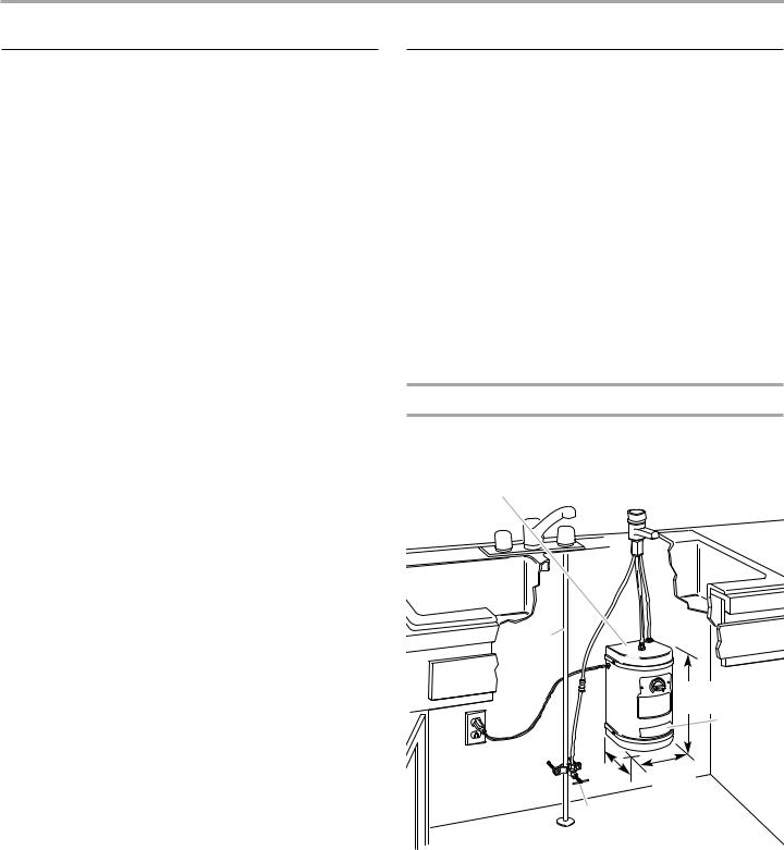
Product dimensions and cabinet requirements
|
Faucet to be installed in a |
|
|
1-3/8" |
(3.5 cm) diameter sink or |
|
countertop cutout. |
|
Tank must be |
1-1/8" |
(2.9 cm) maximum countertop |
mounted vertically. |
or sink thickness |
|
cold water |
|
|
supply line |
|
|
|
|
11-1/8" |
|
|
(28.3 cm) |
|
|
model/serial |
|
|
number label |
42" (106.7 cm) maximum |
|
|
from electrical outlet to |
7-7/8" |
6-7/8" |
hot water dispenser tank. |
(20.0 cm) |
(17.5 cm) |
|
Saddle valve or hard plumbed |
|
|
connection to water supply line. |
|
3
Electrical Requirements
 WARNING
Electrical Shock Hazard
Plug into a grounded 3 prong outlet.
Do not remove ground prong.
Do not use an adapter.
Do not use an extension cord.
Failure to follow these instructions can result in death, fire, or electrical shock.
A 120-volt, 60 Hz, AC-only 15 or 20 amp fused, grounded electrical supply is required. It is recommended that a separate circuit serving only your hot water dispenser be provided. Use an outlet that cannot be turned on/off by a switch.
Recommended ground method
This appliance is equipped with a power supply cord having a 3 prong ground plug. To minimize possible shock hazard, the cord must be plugged into mating, 3 prong, ground-type outlet, grounded in accordance with all national and local codes and ordinances. If a mating outlet is not available, it is the personal responsibility and obligation of the customer to have a properly grounded, 3 prong outlet installed by a qualified electrician.
Water Supply Requirements
If local codes permit, the hot water dispenser feed line should be connected to the cold water supply line using a saddle valve or another means for providing a 1/4" tube to connect to the dispenser. If a saddle valve is used, do not use a piercing type or 3/16" saddle valve, which reduces water flow and clogs more easily.
IMPORTANT: If local codes do not permit the use of saddle valves, special feed valves can be obtained from your local plumbing supply distributor.
Connection to hot water line is not recommended. Energy will be wasted in heating the water twice and may produce an undesirable taste.
A water filter is recommended if your water supply contains sand, grit or other particles, or has a known taste or odor issue. If a water filter system is used, the water pressure to the hot water dispenser system from the filter needs to be a minimum of 20 psi (138 kPa) for proper operation. If the water pressure to the hot water dispenser system is less than 20 psi (138 kPa), a booster pump can be added.
IMPORTANT: If the water pressure to the hot water dispenser system is less than 20 psi (138 kPa), performance may be affected.
INSTALLATION INSTRUCTIONS
Please complete the “Record your model’s information” section on the front cover before beginning installation.
This hot water dispenser is not a water purifier. Some installations may require a water filtering system to improve the quality of water.
Installing the Faucet
1.Determine where you will install your hot water dispenser. Check below sink to assure that reinforcing ribs, support brackets or cabinet construction will not interfere with faucet.
2.Knock out plug from hole in sink or cut a hole in sink or countertop.
NOTE: It is recommended that only a licensed plumber or professional installer cut an opening in the sink or countertop.
3.Carefully straighten tubing so that it will go through hole in sink or countertop.
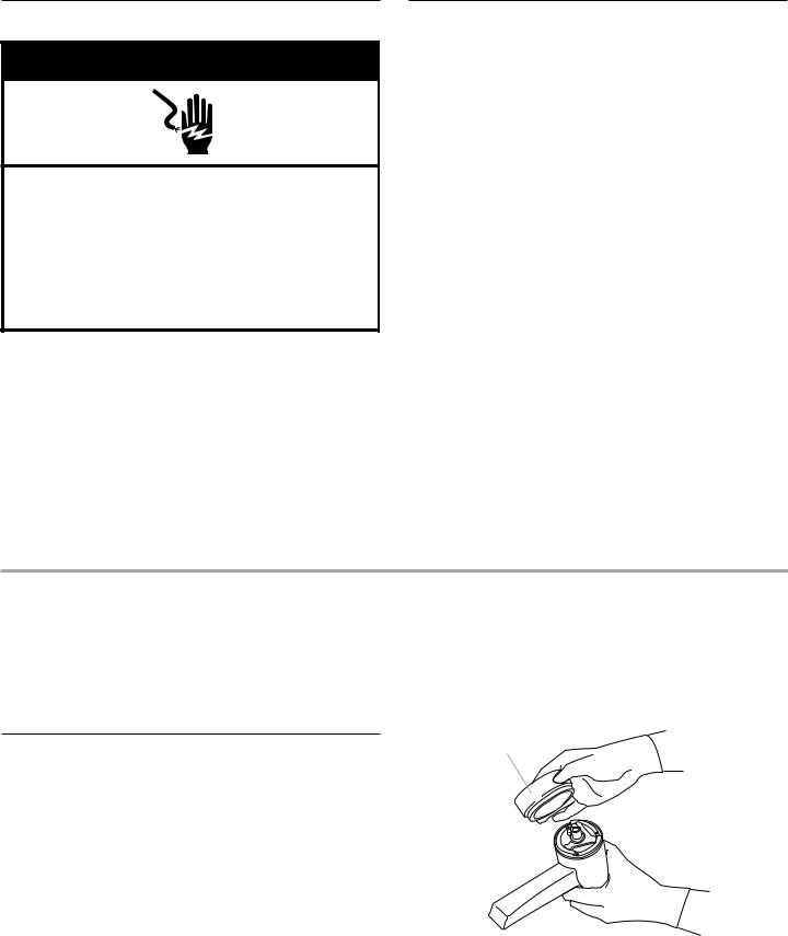
4.Remove masking tape and tag from spout assembly. Do not remove quick-connect fittings from spout tubing or tank tubing. Do not replace quick-connect fittings with brass fittings. Brass fittings can cause lead contamination.
Carefully pull On/Off Cap off the spout assembly and set aside.
On/Off cap
4

5.Lay spout assembly on flat surface with coiled tubing facing up. Using one hand to hold tubing just below spout, carefully straighten tubing with other hand. Slide gasket over tubing so that lip side of gasket is seated into base of spout.
gasket 
6.Loosen square nut until it is flush with end of the mounting screw. Tip spout bracket against mounting screw. (Bracket will form a “y” when in the correct position.) Hold nut, bracket, gasket and tubing in position and insert into hole in sink or counter.
mounting screw |
|
square nut |
bracket |
7.Pull up on spout body to keep tension on spout mounting bracket and nut. Tighten screw inside the spout until spout is securely in position. Do not overtighten.
4.Use two screws (and plastic anchors if attaching to dry wall) to fasten mounting bracket to wall. Hang tank on bracket.
IMPORTANT: Do not plug power supply cord into outlet at this time.
2-1/4"
(5.7 cm)
off position |
mounting |
bracket |
5.IMPORTANT: Do not lengthen, twist or tightly bend tubing. Do not use any sealing compounds.
Connect the longest 1/4" copper faucet tube to the rear easyconnect fitting on top of tank. Push tubing straight into fitting as far as it will go. Pull on tubing. The tubing should not come out when properly installed.
copper |
|
faucet tube |
collet |
|
easy-connect fitting
NOTE: If you need to remove tubing, push down on collet. Pull tubing out of easy-connect fitting. It is easier to push the collet down if a 1/4" or 7 mm open-end wrench is used as shown.
copper |
1/4" or 7 mm |
faucet tube |
open-end |
|
wrench |
collet |
|
8. Snap on On/Off Cap.
Installing the Tank
1.Position tank vertically beneath faucet so that the longer copper tube from the faucet reaches the easy-connect fitting on top of the tank.
2.Use a pencil to mark on the wall where the top of tank needs to be located. Set tank aside. Mark a second line 2-1/4"
(5.7 cm) below the first line.
IMPORTANT: The tank must be positioned so that the copper tubing and flexible tubing from the faucet does not kink.
3.Position mounting bracket on wall so that bottom of mounting bracket is even with the lower line.
6.Connect the flexible tube from the faucet to the center tank tube. Make sure the flexible tube does not kink. To avoid kinking, the tube may be shortened.
The center tank tube is not an easy-connect fitting. To connect the flexible tube, use pliers and open the supplied hose clamp. Slide the clamp onto the flexible tube about 2" (5 cm) from the tube end.
flexible tube
hose clamp
tank  tube
tube
5

7.Push the flexible tube down onto the tank tube as far as it will go. Position the hose clamp so that it is close to the end of flexible tube.
hose  clamp
clamp
8. |
Install saddle valve kit |
parts as needed to |
|
connect 1/4" (6.4 mm) |
faucet easy-connect fitting |
|
to cold water supply |
|
9. |
Flush line into bucket |
any debris that may |
|
have been trapped in |
plumbing connection. |
10. |
Check that water flows |
there are no leaks. |
11. |
Connect 1/4" water |
to faucet copper tubing |
|
with the factory-assembled |
fitting. Push water |
|
supply line tubing |
as far as it will go. Pull |
|
on tubing. The tubing |
out when properly |
|
installed. |
|
factory easy-connect
NOTE: If you need to remove tubing, push down on collet and pull tubing out of easy-connect fitting.
IMPORTANT: For proper operation, do not remove the factory-assembled easy-connect fitting from tube.
12. Open water line to faucet.
Complete Installation
IMPORTANT: The hot water dispenser can be damaged if the following steps are not followed.
NOTE: Do not plug power supply cord into outlet.
1. Turn Temperature Control counterclockwise to “Off” position.
2.Push down and turn the faucet cap clockwise to open faucet. Hold cap open until water flows from the faucet (about 1 to 1-1/2 minutes).
On
3. Release faucet cap. Check for leaks.
NOTE: Make sure the Temperature Control is in the “Off” position before plugging hot water dispenser into power supply. If tank is empty and thermostat is in an “On” position when the power supply cord is connected, the heater will overheat causing an unpleasant taste, black specks in the water, and permanent damage to the hot water dispenser.
 WARNING
Electrical Shock Hazard
Plug into a grounded 3 prong outlet.
Do not remove ground prong.
Do not use an adapter.
Do not use an extension cord.
Failure to follow these instructions can result in death, fire, or electrical shock.
4.Once water is flowing from faucet, the water heating tank has been filled with water. Plug power supply cord into grounded 3 prong outlet.
5.Turn Temperature Control clockwise to highest position.
Water in tank will reach maximum temperature in about 15 minutes.
NOTES:
•When water is heating, you may hear gurgling noises coming from the tank.
•There may also be a small amount of spitting or hot water flow from the faucet. This is normal for the initial heat-up of the dispenser.
•The Temperature Control controls tank heater, not water delivery. Rotate Temperature Control clockwise to make water hotter, counterclockwise to lower water temperature.
•Turn Temperature Control to lower temperature setting if you notice vapor or hear boiling noise.
6
HOT WATER DISPENSER USE
Before first use:
After the tank has been in operation for a minimum of 15 minutes, push and turn the faucet cap and allow water to flow for about 1 minute. Release the faucet cap and allow the water to reheat for about 15 minutes prior to use.
Check that all installation steps were completed.
Temperature control
The water temperature is thermostatically controlled. It can be adjusted from “Off” to about 190°F (88°C).
To raise or lower the temperature, turn the Temperature Control. The “Max” setting is recommended for best performance. However, under certain conditions, it is possible for the water to boil when the Temperature Control is set at “Max.” If you see any vapor or hear boiling, turn Temperature Control to lower temperature as necessary.
Dispensing hot water
Push down and turn the faucet cap clockwise and hold until desired amount of hot water is obtained. There is a small delay from the time the faucet cap is turned until hot water is dispensed. This delay is normal.
HOT WATER DISPENSER CARE
Energy-saving tips and preparation for periods of nonuse.
On average, you will use your hot water dispenser to heat 7 to 8 cups (1.7 to 1.9 liters) of water per day. This uses only 19 kilowatt-hours of energy per month. So it is not necessary to turn off the hot water dispenser each night to conserve energy.
However, if the hot water dispenser will not be used for an extended period of time, follow these instructions:
For short periods (2-30 days of nonuse).
Set the Temperature Control to the “Off” position to conserve energy.
For long periods of nonuse (winterizing, seasonal storage or protection from freezing):
1.Turn Temperature Control to the “Off” position.
2.Unplug hot water dispenser power supply cord.
3.Turn faucet cap, hold and run water until water is cold.
4.Turn supply valve off.
5.Remove the copper faucet tube by pressing the collet down and pulling the copper faucet tube up. It is easier to push the collet down if a 1/4" or 7 mm open-end wrench is used as shown.
copper |
1/4" or 7 mm |
faucet tube |
open-end |
|
wrench |
collet |
|
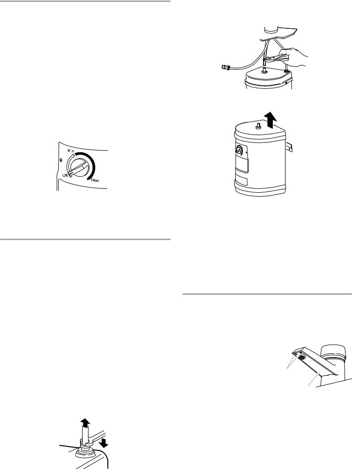
6.Using pliers, open the hose clamp on the flexible tube and slide the clamp about 2" (5 cm) from the end of the tubing. Remove the flexible tube from the tank tube.
7.Lift the hot water dispenser tank up and off the mounting bracket.
mounting  bracket
8.Hold the hot water dispenser tank over a sink, turn the dispenser upside down and let all the water drain out of the tank tube.
9.When the hot water dispenser tank is empty, reinstall the tank on the mounting bracket.
10.Reconnect the copper faucet tube and the flexible tube (See “Installing the faucet” steps 5-7).
When ready to use the dispenser again, follow “Complete Installation” steps 1-5. Do not turn unit on if tank is empty. Damage to the unit will result and is not covered by the warranty.
Cleaning the Faucet Screen
If you have very hard water, and you notice that the water flow is reduced, it may be necessary to clean the spout screen.
1.Turn Temperature Control to the “Off” position. Push down and turn On/Off Cap clockwise and run water until it is cold to avoid possibility of burn.
2. |
Remove the two spout screws. |
|
3. |
Remove spout base plate. |
|
4. |
Pull the screen assembly out of |
screws |
|
the hot water tube. |
|
|
|
|
5. |
Use a small brush and vinegar to |
base plate |
|
remove hard-water deposit. |
If deposit has hardened, soak in vinegar for an hour or two. Then use a brush to clean.
6.Replace screen assembly in tube. Reattach plate back onto spout.
7.Turn Temperature Control to the “Max” setting. The dispenser will be ready in about 15 minutes.
7

Before Calling for Service
If hot water dispenser does not operate, check these points first:
■Has circuit breaker tripped or house fuse blown?
■Is power supply cord plugged into a grounded 3 prong outlet?
■Is the Temperature Control set to the “Off” position?
■Has the water supply been turned off?
■Is the electrical outlet controlled by a switch?
Troubleshooting Guide
If you need more help, check the chart below. This could save you the cost of a service call for a problem that is not covered by the warranty.
PROBLEM |
CHECK THE FOLLOWING |
Water is not hot. |
■ Check that the circuit breaker is not |
|
tripped or the house fuse blown. |
|
■ Check that power supply cord is |
|
plugged into a grounded 3 prong outlet. |
|
■ Check if the electrical outlet is operated |
|
by a switch. The switch may have |
|
turned power off. |
|
■ Cold water in tank is still being heated. |
|
Wait 15 minutes and check temperature |
|
again. |
|
■ Check that the Temperature Control is |
|
set to the “Max” setting. |
|
|
Vapor appears, |
■ Adjust Temperature Control to a lower |
dispenser makes |
setting that eliminates the vapor or |
boiling water noises, |
noise. If you live at a high altitude, you |
or water is too hot. |
may need to lower the thermostat |
|
setting to keep water from boiling. |
Hot water drips or sputters from faucet.
■Check that tubing is not bent or kinked.
■Adjust Temperature Control to a lower setting that eliminates the drips or sputters.
■Check that faucet screen is not clogged. See “Hot water dispenser care.”
■Check for proper installation of copper tubing from faucet to storage tank and from faucet to cold water line. See “Installation instructions.”
PROBLEM |
CHECK THE FOLLOWING |
Water does not flow from faucet.
■Check that water supply valve is open.
■Check that faucet screen is not clogged. See “Hot water dispenser care.”
■Check for hoses with kinks.
■If a water filter is used, check that water pressure to hot water dispenser is 20 psi (138 kPa) minimum.
Water has an |
■ Hot water dispenser is attached to hot |
unpleasant taste. |
water line. Attach to cold water line. |
|
■ Install a water filtration system on cold |
|
water line to dispenser. |
|
■ If the dispenser has not been used for 3 |
|
or more days or if only 1 to 3 cups of |
|
water are dispensed in a day, the tank |
|
may need to be purged. Hold the cap |
|
open for 2 to 3 minutes to purge the old |
|
water from the tank. Allow new water in |
|
tank to reach maximum temperature |
|
(approximately 15 minutes) before |
|
dispensing water. |
|
|
Water flows very |
■ If a water filtration system is used, check |
slowly from faucet, |
that the water pressure from the filter |
less than 1/2 gallon |
system to the hot water dispenser is 20 |
(1.9 liter) per minute. |
psi (138 kPa). |
8
 Loading...