


CONSUMER SERVICES TECHNICAL EDUCATION GROUP PRESENTS KR-35
SELF-CLEANING
SLIDE-IN GAS
RANGE
Model: GW395LEP
JOB AID
Part No. 8178455

FORWARD
This Whirlpool Job Aid, “Self-Cleaning Slide-In Gas Range,” (Part #8178455), provides the technician with information on the installation, operation, and service of the Self-Cleaning SlideIn Gas Range. It is to be used as a training Job Aid and Service Manual. For specific information on the model being serviced, refer to the “Use and Care Guide,” or “Wiring Diagram” provided with the gas range.
The Wiring Diagram and Strip Circuits used in this Job Aid are typical and should be used for training purposes only. Always use the Wiring Diagram supplied with the product when servicing the unit.
GOALS AND OBJECTIVES
The goal of this Job Aid is to provide detailed information that will enable the service technician to properly diagnose malfunctions and repair the Whirlpool Self-Cleaning Slide-In Gas Range.
The objectives of this Job Aid are to:
•Understand and follow proper safety precautions.
•Successfully troubleshoot and diagnose malfunctions.
•Successfully perform necessary repairs.
•Successfully return the range to its proper operational status.
WHIRLPOOL CORPORATION assumes no responsibility for any repairs made on our products by anyone other than Authorized Service Technicians.
Copyright © 2004, Whirlpool Corporation, Benton Harbor, MI 49022
- ii -
TABLE OF CONTENTS
|
Page |
GENERAL............................................................................................................................... |
1-1 |
Safety First......................................................................................................................... |
1-1 |
Model & Serial Number Designations ................................................................................ |
1-2 |
Model & Serial Number Label & Wiring Diagram Locations .............................................. |
1-3 |
Specifications..................................................................................................................... |
1-4 |
Whirlpool Gas Range Warranty ......................................................................................... |
1-6 |
INSTALLATION INFORMATION ........................................................................................... |
2-1 |
Gas Supply Requirements ................................................................................................. |
2-1 |
Electrical Requirements ..................................................................................................... |
2-3 |
L.P. Gas Conversion.......................................................................................................... |
2-4 |
Adjusting For The Proper Flame........................................................................................ |
2-8 |
Installing The Anti-Tip Bracket ........................................................................................... |
2-9 |
THEORY OF OPERATION ..................................................................................................... |
3-1 |
Electronic Oven Control System Functions ....................................................................... |
3-1 |
COMPONENT ACCESS ......................................................................................................... |
4-1 |
Component Locations ........................................................................................................ |
4-1 |
Removing The Control Panel And The Electronic Oven Control Board & |
|
User Interface ................................................................................................................. |
4-2 |
Removing The Ignition Switches, A Gas Valve, |
|
And The Control And Cooling Fan TODs ....................................................................... |
4-4 |
Removing The Door Latch Assembly And The Spark Module (DSI) ................................. |
4-6 |
Removing The Cooktop, And A Surface Burner & Ignitor.................................................. |
4-8 |
Removing The Rear Panel .............................................................................................. |
4-10 |
Removing An Oven Light Socket Assembly .................................................................... |
4-11 |
Removing The Broil Burner And Ignitor ........................................................................... |
4-12 |
Removing The Bake Burner And Ignitor .......................................................................... |
4-14 |
Removing The Oven Temperature Sensor ...................................................................... |
4-16 |
Removing The Cooling Fan ............................................................................................. |
4-17 |
Removing The Oven TOD ............................................................................................... |
4-18 |
Removing The Gas Distribution Valve ............................................................................. |
4-19 |
Removing The Power Supply Cord ................................................................................. |
4-20 |
Removing A Side Panel ................................................................................................... |
4-21 |
Removing & Reinstalling The Oven Door ........................................................................ |
4-22 |
Removing The Oven Door Gasket................................................................................... |
4-23 |
Removing The Decorative Glass And Oven Door Handle, |
|
The Hinges, And The Oven Door Glass ...................................................................... |
4-24 |
- iii -
|
Page |
COMPONENT TESTING ........................................................................................................ |
5-1 |
Control & Cooling Fan TODs ............................................................................................. |
5-1 |
Ignition Switches ................................................................................................................ |
5-2 |
Door Latch Assembly......................................................................................................... |
5-3 |
Oven Temperature Sensor ................................................................................................ |
5-3 |
Cooling Fan Motor ............................................................................................................. |
5-4 |
Oven TOD.......................................................................................................................... |
5-4 |
Gas Distribution Valve ....................................................................................................... |
5-5 |
Gas Valve .......................................................................................................................... |
5-5 |
Clock .................................................................................................................................. |
5-6 |
Keypad Layout ................................................................................................................... |
5-6 |
Display Board & Connector Pinouts .................................................................................. |
5-7 |
DIAGNOSTICS & TROUBLESHOOTING .............................................................................. |
6-1 |
Diagnostics ........................................................................................................................ |
6-1 |
Failure/Error Display Codes........................................................................................... |
6-1 |
Hidden EOC Functions ................................................................................................. |
6-2 |
Temperature Adjustment ............................................................................................... |
6-2 |
EZ354 ............................................................................................................................ |
6-3 |
Troubleshooting Chart ....................................................................................................... |
6-4 |
WIRING DIAGRAM & STRIP CIRCUITS ............................................................................... |
7-1 |
Wiring Diagram .................................................................................................................. |
7-1 |
Strip Circuits ...................................................................................................................... |
7-2 |
- iv -

GENERAL
SAFETY FIRST
Your safety and the safety of others is very important.
We have provided many important safety messages in this Job Aid and on the appliance. Always read and obey all safety messages.
This is the safety alert symbol.
This symbol alerts you to hazards that can kill or hurt you and others.
All safety messages will follow the safety alert symbol and either the word “DANGER” or “WARNING.” These words mean:
 DANGER
 WARNING
You can be killed or seriously injured if you don’t immediately follow instructions.
You can be killed or seriously injured if you don’t follow instructions.
All safety messages will tell you what the potential hazard is, tell you how to reduce the chance of injury, and tell you what can happen if the instructions are not followed.
1-1

MODEL & SERIAL NUMBER DESIGNATIONS
MODEL NUMBER
MODEL NUMBER |
|
G |
W |
3 9 5 L E P Q |
|
|
|
|
|
PRODUCT GROUP |
|
|
|
|
R = ELECTRIC RANGES |
|
|
||
S = GAS RANGES |
|
|
|
|
G = WHIRLPOOL GOLD RANGE |
|
|
||
|
|
|
|
|
PRODUCT IDENTIFICATION |
|
|||
A = ACCESSORY |
K = KITS |
|
||
B = BUILT-IN |
M = MV COMBO |
|
||
C = COOKTOP |
S = SET-IN |
|
||
E = EYE-LEVEL |
W = SLIDE-IN GAS |
|
||
F = FREESTANDING |
Y = SLIDE-IN ELECTRIC |
|
||
H = HOODS |
|
|
|
|
|
|
|
|
|
MODEL SIZE
3 = 30" SLIDE-IN
4 = 40" SLIDE-IN
5 = 36" SLIDE-IN
6 = 30" SET-IN RANGES
OVEN TYPE
0 THRU 3 = STANDARD PORCELAIN
4 THRU 9 = PYROLYTIC SELF-CLEAN
FEATURE / VARIATIONS
ELECTRIC
0, 1, 2, 5, 7 = COIL ELEMENTS
4 = STANDARD PATTERN CERAMIC 6, 8, 9 = DELUXE PATTERN CERAMIC
GAS
0, 1, 2, 3, 4, 6 = OPEN BURNER 5 & 7 = SEALED BURNER
DOOR TYPE
B = SOLID BLACK GLASS
L = LARGE WINDOW
O = METAL OVEN DOOR
P = STANDARD WINDOW GLASS
FEATURE CODE
E = ELECTRONIC IGNITION (GAS ONLY)
S = STANDING IGNITION (GAS ONLY)
C = COLOR COORDINATED GLASS (BEFORE 1998)
X = NOT DEFINED
YEAR OF INTRODUCTION
P = 2004
COLOR CODE
B = BLACK
Q = WHITE ON WHITE
S = STAINLESS STEEL
T = BISCUIT
SERIAL NUMBER
SERIAL NUMBER |
X R 07 1 2 3 4 5 |
MANUFACTURING SITE
X = OXFORD, MS
YEAR OF PRODUCTION
R = 2004
WEEK OF PRODUCTION
(7th WEEK)
PRODUCT SEQUENCE NUMBER
1-2
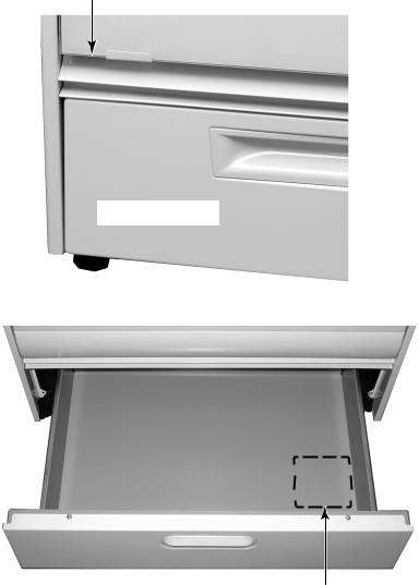
MODEL & SERIAL NUMBER LABEL & WIRING DIAGRAM LOCATIONS
The Model/Serial Number label and Wiring Diagram locations are shown below.
Model/Serial Number Location
(Above Storage Drawer)
Storage Drawer
Wiring Diagram Location
(On Underside Of Drawer)
1-3
SPECIFICATIONS |
||
|
|
|
Model # |
GW395LEP Q/B/T/S |
|
|
|
|
Model Description |
Gas Self-Clean |
|
|
|
|
Oven Control Type |
EZ354 |
|
|
|
|
OVEN CONTROL FUNCTIONS |
|
|
|
|
|
Convect bake |
No |
|
|
|
|
Bake |
Yes |
|
|
|
|
Temperature range |
170 to 500°F |
|
|
|
|
Custom broil |
Yes |
|
|
|
|
Temperature range |
300 to 500°F |
|
|
|
|
Temperature control |
Temperature up/down buttons |
|
(5 degree increments) |
||
|
||
|
|
|
Self-clean |
Yes, variable time |
|
|
|
|
Time set range |
2:30 to 4:30 (15 min. increments) |
|
|
|
|
Delay bake |
Yes (Cook time, Stop time buttons) |
|
|
|
|
Timer |
Yes (up to 12hrs, 59 min. max.) |
|
|
|
|
Oven light (manual) |
Yes |
|
|
|
|
Control lockout |
Yes |
|
|
|
|
Pre-heat countdown timer |
Yes |
|
|
|
|
Control overlay color |
Q=White/Nestle, B=Black/blk Divide, |
|
T=Biscuit/dk biscuit, S=Black/blk Divide |
||
|
||
|
|
|
Oven Heating Indicator Light |
In display |
|
|
|
|
|
Select F/C temperature, temperature |
|
Hidden functions |
calibration offset, disable/enable timer |
|
reminder signals, disable/enable cycle end |
||
|
||
|
audible signals |
|
|
|
|
CONSOLE FEATURES |
|
|
|
|
|
Location |
Front |
|
|
|
|
Burner "ON" Indicator Light |
No |
|
|
|
|
Burner Controls |
Push to turn, infinite |
|
|
|
|
Valve degrees of rotation |
210 degrees |
|
|
|
|
COOKTOP FEATURES |
|
|
|
|
|
Burner Type |
Sealed |
|
|
|
|
Ignition |
Electronic |
|
|
|
|
Burner Configuration |
|
|
|
|
|
Right Front Burner |
6,000 btu |
|
|
|
|
Left Front Burner |
14,000 btu |
|
|
|
|
Right Rear Burner |
12,000 btu |
|
|
|
|
Left Rear Burner |
6,000 btu |
|
|
|
|
Lift Top |
No |
|
|
|
|
OVEN FEATURES |
|
|
|
|
|
Oven cleaning type |
Self-clean |
|
|
|
|
Accubake system |
Yes |
|
|
|
|
Number of temperature sensors |
1 |
|
|
|
|
Oven Capacity |
4.3 Cu. Ft. |
|
|
|
|
Broil Burner |
10,000 btu |
|
|
|
|
Door Position in Broil |
Closed |
|
|
|
|
Bake Burner |
15,500 btu |
|
|
|
|
Oven Light |
Yes |
|
|
|
|
1-4
Model # |
GW395LEP Q/B/T/S |
|
|
OVEN DOOR FEATURES |
|
|
|
Door Latch |
Yes-Motorized |
|
|
Removable Door |
Yes |
|
|
STORAGE/WARMING DRAWER |
|
|
|
Storage Drawer |
Yes |
|
|
LITERATURE |
|
|
|
Use & Care Guide |
Yes (English + French) |
|
|
Tech Sheets/Wiring Diagrams |
9757668 |
|
|
Installation Instructions |
Yes (English + French) |
|
|
Service Manual/Job Aid |
8178455 |
|
|
DIMENSIONS |
|
|
|
Height-Overall |
35.9" |
|
|
Width |
29.875" |
|
|
OTHER SPECIFICATIONS |
|
|
|
LP Convertible |
Yes, conversion orifices included |
|
|
Agency Approval |
CSA |
Power cord |
Included |
|
|
Anti-Tip Device w/ Unit |
Floor Bracket |
|
|
ACCESSORIES |
|
|
|
|
Included, matches body color, to close gap |
Trim Kit |
from rear of unit to wall (previous |
|
freestanding installation) |
|
|
1-5
WHIRLPOOL GAS RANGE WARRANTY
LENGTH OF |
WHIRLPOOL |
WHIRLPOOL |
|
WARRANTY: |
WILL PAY FOR: |
WILL NOT PAY FOR: |
|
|
|
|
|
ONE-YEAR FULL |
FSP® replacement |
A. Service calls to: |
|
WARRANTY |
parts and repair |
1. |
Correct the installation of the range. |
FROM DATE OF |
labor costs to |
2. |
Instruct you how to use the range. |
PURCHASE. |
correct defects in |
3. |
Replace house fuses or correct house wiring. |
|
materials or work- |
4. |
Replace owner-accessible light bulbs. |
|
manship. Service |
5. |
Correct house plumbing. |
|
must be provided |
B. Repairs when the range is used in other than |
|
|
by an authorized |
||
|
|
normal, single-family household use. |
|
|
Whirlpool service |
|
|
|
C. Pickup and delivery. The range is designed to |
||
|
company. |
||
|
|
be repaired in the home. |
|
|
|
|
|
|
|
D. Damage to the range caused by accident, alter- |
|
|
|
|
ation, misuse, abuse, fire, flood, acts of God, or |
|
|
|
use of products not approved by Whirlpool. |
|
|
E. Repairs to parts or systems resulting from unau- |
|
|
|
|
thorized modifications made to the appliance. |
|
|
F. In Canada, travel or transportation expenses for |
|
|
|
|
customers who reside in remote areas. |
|
|
G. Replacement parts or repair labor costs for units |
|
|
|
|
operated outside the United States and Canada. |
|
|
|
|
WHIRLPOOL CORPORATION AND WHIRLPOOL CANADA INC. SHALL NOT BE LIABLE FOR INCIDENTAL OR CONSEQUENTIAL DAMAGES.
Some states and provinces do not allow the exclusion or limitation of incidental or consequential damages so this exclusion or limitation may not apply to you. This warranty gives you specific legal rights and you may also have other rights which vary from state to state or province to province.
Outside the 50 United States and Canada, this warranty does not apply. Contact your authorized Whirlpool dealer to determine if another warranty applies.
If you need service first see “Troubleshooting” in the “Use & Care Guide.” Additional help can be found by checking “Assistance or Service” or call our Customer Interaction Center at 1-800-253-1301 from anywhere in the U.S.A., or write: Whirlpool Brand Home Appliances, Customer Interaction Center, 553 Benson Road, Benton Harbor, MI 49022-2692. In Canada, call Whirlpool Canada Inc. at 1-800-807-6777.
1-6
INSTALLATION INFORMATION
GAS SUPPLY REQUIREMENTS
 WARNING
Explosion Hazard
Use a new AGA or CSA approved gas supply line.
Install a shutoff valve.
Securely tighten all gas connections.
If connected to L.P. gas, have a qualified person make sure gas pressure does not exceed 14″ water column.
Examples of a qualified person include licensed heating personnel, authorized gas company personnel, and authorized service personnel.
Failure to do so can result in death, explosion, or fire.
Observe all governing codes and ordinances.
IMPORTANT: Range must be connected to a regulated gas supply.
1.This installation must conform with local codes and ordinances. In the absence of local codes, installations must conform with American National Standard, National Fuel Gas Code ANSI Z223.1—latest edition* or CANI-B149—latest edition** installation codes.
Copies of the standards listed may be obtained from:
*American Gas Association 1515 Wilson Boulevard Arlington, Virginia 22209
**CSA International
8501 East Pleasant Valley Road Cleveland, Ohio 44131-5575
2.Input ratings shown on the model/serial rating plate are for elevations up to 2,000 feet (609.6 m). For elevations above 2,000 feet (609.6 m), ratings are reduced at a rate of 4% for each 1,000 feet (304.8 m) above sea level. (Not applicable for Canada.)
3.This range is equipped for use with Natural gas. It is design-certified by AGA/CSA for Natural and L.P. gas with appropriate conversion. Conversion to L.P. gas can be made using the kit included in the literature package. The model/serial rating plate has information on the type of gas that can be used. If this information does not agree with the type of gas available, check with your Whirlpool dealer.
4.Provide a gas supply line of 3/4″ (1.9 cm) rigid pipe to the range location. A smaller size pipe on long runs may result in insufficient gas supply. Pipe-joint compounds appropriate for use with L.P. gas must be
used. With L.P. gas, piping or tubing size can be 1/2″ (1.3 cm) minimum. L.P. gas suppliers usually determine the size and materials used on the system.
5.If local codes permit, a new AGA/CSA
design-certified, 4-5 foot (122 -152.4 cm) long, 1/2″ (1.3 cm) or 3/4″ (1.9 cm) I.D., flexible metal appliance connector is recommended for connecting this range to the gas supply line. Do Not kink or damage
the flexible tubing when moving the range. A 1/2″ (1.3 cm) male pipe thread is needed for connection to pressure regulator female pipe threads.
Flexible Gas Supply Line
Continued on the next page.
2-1

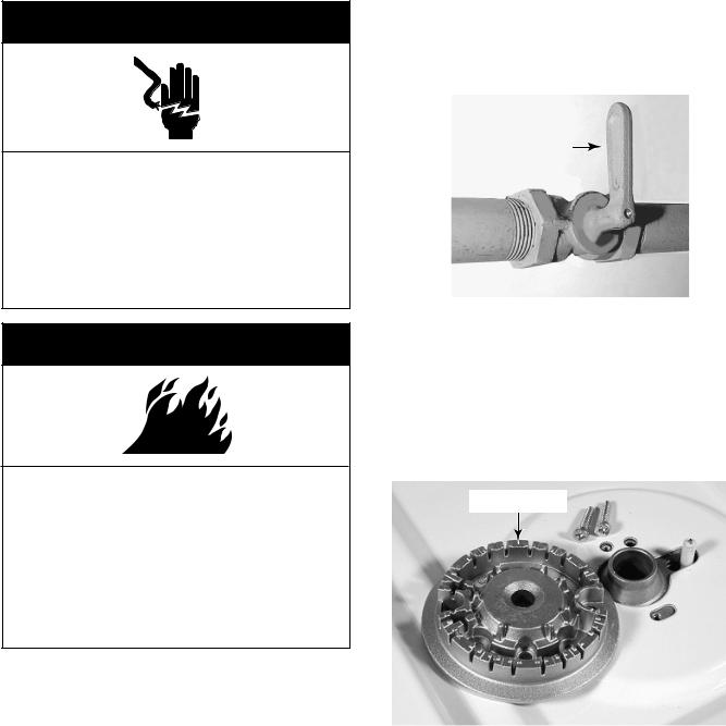
6.The supply line shall be equipped with an approved shutoff valve. This valve should be located in the same room, but external to the range, and should be in a location that allows ease of opening and closing. Do Not block access to shutoff valve.
Manual Shutoff Valve
OPEN Position
To Range
Gas Supply Line
7.If rigid pipe is used as a gas supply line, a combination of pipe fittings must be used to obtain an in-line connection to the range. All strains must be removed from the supply and fuel lines so the range will be level and in line.
8.The regulator setting must be checked at a minimum of 1 inch water column above the manifold pressure. The inlet pressure to the regulator should be as follows for operation:
Natural gas:
Manifold pressure—5 inches Maximum pressure—14 inches
L.P. gas:
Manifold pressure—10 inches Maximum pressure—14 inches
9.Line pressure testing: Testing above 1/2 psi (gauge)
The range and its individual shutoff valve must be disconnected from the gas supply piping system during any pressure testing of that system at test pressures greater than 1/2 psig (3.5 kPa).
Testing at 1/2 psi (gauge) or lower
The range must be isolated from the gas supply piping system by closing its individual manual shutoff valve during any pressure testing of the gas supply piping system at test pressures equal to or less than 1/2 psig (3.5 kPa).
2-2
ELECTRICAL REQUIREMENTS
 WARNING
Electrical Shock Hazard
Plug into a grounded 3 prong outlet.
Do not remove ground prong.
Do not use an adapter.
Do not use an extension cord.
Failure to follow these instructions can result in death, fire, or electrical shock.
If codes permit and a separate ground wire is used, it is recommended that a qualified electrician determine that the ground path is adequate.
Do Not ground to a gas pipe.
Check with a qualified electrician if you are not sure range is grounded.
Do Not have a fuse in the neutral or ground circuit.
A 120-volt, 60-Hz, AC-only, 15-ampere, fused electrical circuit is required. A time-delay fuse or circuit breaker is recommended. It is recommended that a separate circuit serving only this range be provided.
Electronic ignition systems operate within wide voltage limits, but proper grounding and polarity are necessary. In addition to checking that the outlet provides 120-volt power and is correctly grounded, the outlet must be checked by a qualified electrician to see if it is wired with correct polarity.
NOTE: The metal chassis of the range MUST be grounded in order for the control panel to work. If the metal chassis of the range is not grounded, NO keypads will operate. Check with a qualified electrician if you are in doubt as to whether the metal chassis of the range is grounded.
Recommended ground method
For personal safety, this range is equipped with a power supply cord having a 3-prong ground plug. To minimize possible shock hazard, the cord must be plugged into a mating 3-prong, ground-type outlet, grounded in accordance with the National Electrical Code, ANSI/NFPA 70—latest edition* or CSA Standard C22.1, Canadian Electrical Code, Part 1,—latest edition** and all local codes and ordinances. If a mating outlet is not available, it is the personal responsibility and obligation of the customer to have a properly grounded, 3-prong outlet installed by a qualified electrician.
Copies of the standards listed may be obtained from:
*National Fire Protection Association Batterymarch Park
Quincy, Massachusetts, 02269
**CSA International
8501 East Pleasant Valley Road Cleveland, Ohio 44131-5575
2-3
L.P. GAS CONVERSION
 WARNING
Electrical Shock Hazard
Disconnect power before servicing.
Replace all parts and panels before operating.
Failure to do so can result in death or electrical shock.
 WARNING
Fire Hazard
Shut off gas supply line valve.
Make all conversions before turning gas supply valve back on.
Failure to follow these instructions could result in explosion, fire, or other injury.
NOTE: Gas conversion from Natural to L.P. gas must be done by a qualified installer. Examples of a qualified installer include licensed heating personnel, authorized gas company personnel, and authorized service personnel.
L.P. gas must not be used unless the L.P. conversion has been made using the kit that is included with this range. See the “Gas Supply Requirements” starting on page 2-1.
1.Check to make sure that the main gas supply line to the range has been shut off, and that the power supply cord is disconnected from the AC outlet.
Gas Valve Handle
To “Shutoff” Position
2.To convert the surface burners for use with L.P. gas:
a)Remove the grates and burner caps from the cooktop.
b)Remove the two screws from each of the burner heads and lift the heads off the cooktop.
Burner Head
2-4
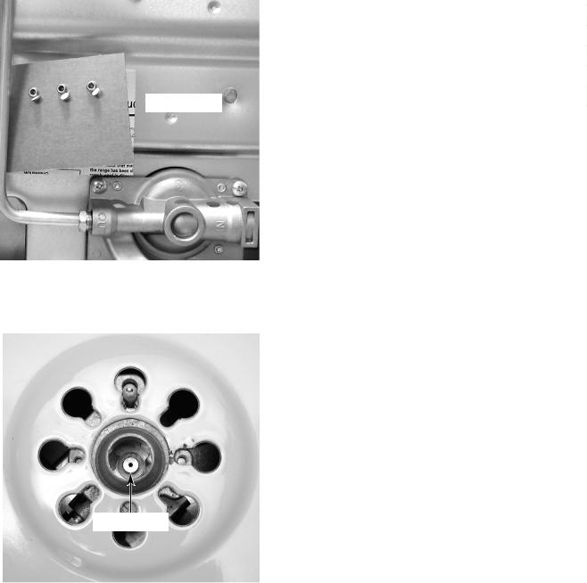
NOTE: The L.P. orifices are fastened to the back of the range near the bottom on a cardboard form.
 Orifice Card
c)Use an 8 mm socket and carefully remove the orifice spud from each of the four burners.
Orifice Spud
d)Install the four L.P. gas orifices in the burners, as shown in the following chart (do not overtighten them):
Burner Location |
Burner Rating |
Color |
Size |
|
Right Front |
5,000 |
BTU |
Red |
0.70 mm |
Left Front |
13,000 |
BTU |
Green |
1.10 mm |
Right Rear |
10,000 |
BTU |
Blue |
0.95 mm |
Left Rear |
5,000 |
BTU |
Red |
0.70 mm |
e)Place the natural gas orifices in the orifice card holes.
3.To convert the broil burner for use with L.P. gas:
a)Open the oven door and remove the oven racks.
b)Use a 1/2″ open-end wrench and turn the orifice hood down snug onto the pin (approximately 2-1/2 turns). DO NOT OVERTIGHTEN THE ORIFICE. The burner flame cannot be properly adjusted if this conversion is not made.
c)Reinstall the oven racks and close the oven door.
Continued on the next page.
2-5

4. To convert the bake burner for use with
L.P. gas:
a)Remove the bake burner from the gas distribution valve orifice (see page 4-14 for the procedure).
b)Use a 1/2″ open-end wrench and turn the bake burner orifice hood down snug onto the pin (approximately 2-1/2 turns).
DO NOT OVERTIGHTEN THE ORIFICE. The burner flame cannot be properly adjusted if this conversion is not made.
Broil Burner Orifice
Bake Burner Orifice Hood
5. To convert the gas distribution valve for use with L.P. gas:
a)Remove the storage drawer from the range.
Orifice
Pin Hood
Natural Gas:
Increases Flame Size
In This Direction
L.P. Gas: |
|
Gas Distribution Valve |
|
Increases Flame Size
In This Direction
2-6

b)Pull the plastic cap off the gas distribution valve conversion cap.
Plastic Cap
c)Unscrew the conversion cap from the gas distribution valve and remove it and the plastic cap. Note the difference between the L.P. and Natural gas ends of the cap.
Conversion Cap Set For
Use With (N) Natural Gas
L.P. Gas |
Natural Gas |
|
d)Install the loop on the plastic cap over the natural gas side of the conversion cap.
e)Install the plastic cap and the conversion cap on the gas distribution valve with the L.P. side facing up (you will see “LP” stamped inside the cap, as shown below).
f) Reinstall the storage drawer.
|
|
|
|
|
|
|
Conversion Cap Set |
||
Plastic Cap |
||||
For Use With L.P. Gas |
||||
|
|
|||
L.P. Gas 
6.Turn the gas supply valve handle on.
Gas Valve Handle To “On” Position
2-7
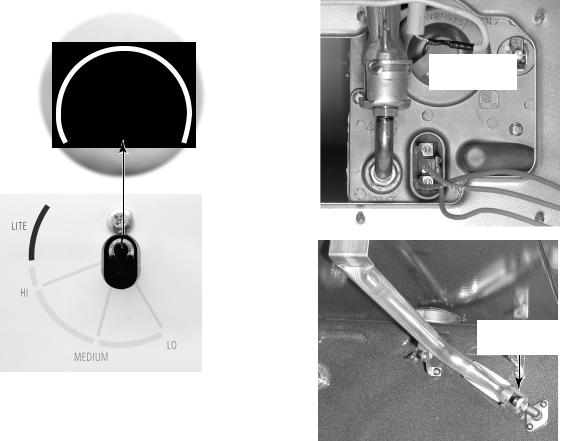
ADJUSTING FOR THE PROPER FLAME
SURFACE BURNERS
1.Turn on one of the surface burners and set the flame to its lowest (LO) setting. The flame should be steady and the inner cone
should be dark blue in color. The size should be approximately 1/4″ (0.64 cm) high.
2.If the low flame needs to be adjusted: a)Remove the control knob.
b)Look inside the gas valve stem and note the small screw. Insert a small screwdriver into the gas valve stem and fit it in the screw slot.
Flame
Adjustment 
Screw
c)Hold the gas valve stem with a pair of pliers, and turn the screw in either di-
rection until the flame size is approximately 1/4″ high.
d)Replace the control knob.
e)Turn the control knob from HI to LO and check to make sure that it remains adjusted properly.
f)Check the other three burners, and adjust them, if necessary.
BAKE & BROIL BURNERS
1.Remove the oven racks and oven bottom.
2.Light the bake and broil burners, then
check their flames. They should be approximately 1/2″ (1.3 cm) high.
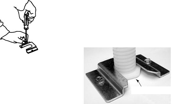
3.If the bake or broil burner flame needs to be adjusted:
a)Loosen the locking screw on the burner air shutter. NOTE: For the bake burner, you will have to remove the unit from its mounting location to access the air shutter.
 Bake Burner
Air Shutter
Broil Burner
Air Shutter
b)Adjust the air shutter until the flame is the proper height. The inner cone should be bluish-green, and the outer mantle should be dark blue. There should be no blowing or lifting of the flame away from the burner ports. NOTE: Natural gas flame does not have a yellow tip.
c) Retighten the air shutter screw.
2-8

INSTALLING THE ANTI-TIP BRACKET
 WARNING
Tip-Over Hazard
A child or adult can tip the range and be killed.
Connect anti-tip bracket to rear range foot.
Reconnect the anti-tip bracket, if the range is moved.
Failure to follow these instructions can result in death or serious burns to children and adults.
PARTS SUPPLIED
(2) Plastic Anchors |
(2) Screws |
(1) Anti-Tip Bracket
NOTE: The anti-tip bracket can be installed to hold either the right or left rear leg of the range.
1.Determine which leg you wish to anchor to the floor.
2.Place the template on the floor in the range opening so that the top edge is against the wall, molding, or cabinet, and the template is in the location where the anti-tip bracket will be installed.
3.Tape the template to the floor.
NOTE: For mounting to a wood floor, proceed with step 4. For concrete or ceramic floors, proceed to step 5.
4.To mount the anti-tip bracket to a wood floor:
a)Use the template to mark the hole locations to be drilled.
b)Use a 1/8″ drill bit and drill the two holes.
Template
Continued on the next page.
2-9
c) Remove the template from the floor.
d)Line up the two mounting holes in the anti-tip bracket with the two holes you just drilled in the floor.
e)Use the two screws that were supplied and fasten the anti-tip bracket to the floor.
5.To mount the anti-tip bracket to a concrete or ceramic floor:
a)Use the template to mark the hole locations to be drilled.
b)Use a 3/16″ drill bit and drill the two holes.
c) Remove the template from the floor.
d)Tap the two plastic anchors into the mounting holes with a hammer.
e)Line up the two mounting holes in the anti-tip bracket with the two holes you just drilled in the floor.
f)Use the two screws that were supplied and fasten the anti-tip bracket to the floor.
6.Move the range close to the cabinet opening and plug the power supply cord into a grounded outlet.
7.Move the range into position and make sure that the rear leveling leg slides into the anti-tip bracket, as shown.
Slide Leg Into Bracket
2-10
THEORY OF OPERATION
ELECTRONIC OVEN CONTROL SYSTEM FUNCTIONS
BAKE PREHEAT
When the user presses the BAKE key, the control displays Pre in 3-digit display area during preheat countdown. The BAKE and ON LEDs are also lit.
If the user queries the set temperature, the control displays the set temperature, a flashing degree symbol, and a solidly lit temperature scale.
If the user changes the set temperature during the preheat cycle, the countdown continues uninterrupted.
When the preheat countdown expires:
1.The control sounds the preheat end audible signal.
2.The control shows the set temperature in the 3-digit display area, along with a solidly lit degree symbol.
3.The BAKE and ON LEDs remain lit. The displayed temperature does not change unless the user changes the set temperature.
Open Door Preheat
If the door is opened during the preheat cycle:
1.An open door display is shown (door LED).
2.Electric Models: Both bake and broil elements will turn off at the end of cycle.
3.Gas Models: The broil burner will turn off as soon as the user opens the door, and the bake burner will turn off after a 15second delay.
4.The preheat countdown continues in background.
BAKE
If the control receives the door-locked signal during an active bake function, the control should perform the following procedure:
1.Moves the door latch to the unlocked position.
2.Waits for the door-unlocked signal from the door switch.
3.If the door-unlocked signal is not received, it terminates the bake function, and sounds the audible failure signal.
4.If the door-locked signal is discontinued, the control continues the Bake function.
3-1
 Loading...