


LG LC340CPO, LC340CPI, LC240CPO, LCN340CP, LCU340CP Service Manual
...website http://www.lgservice.com
e-mail http://www.lgeservice.com/techsup.html
LG
LG
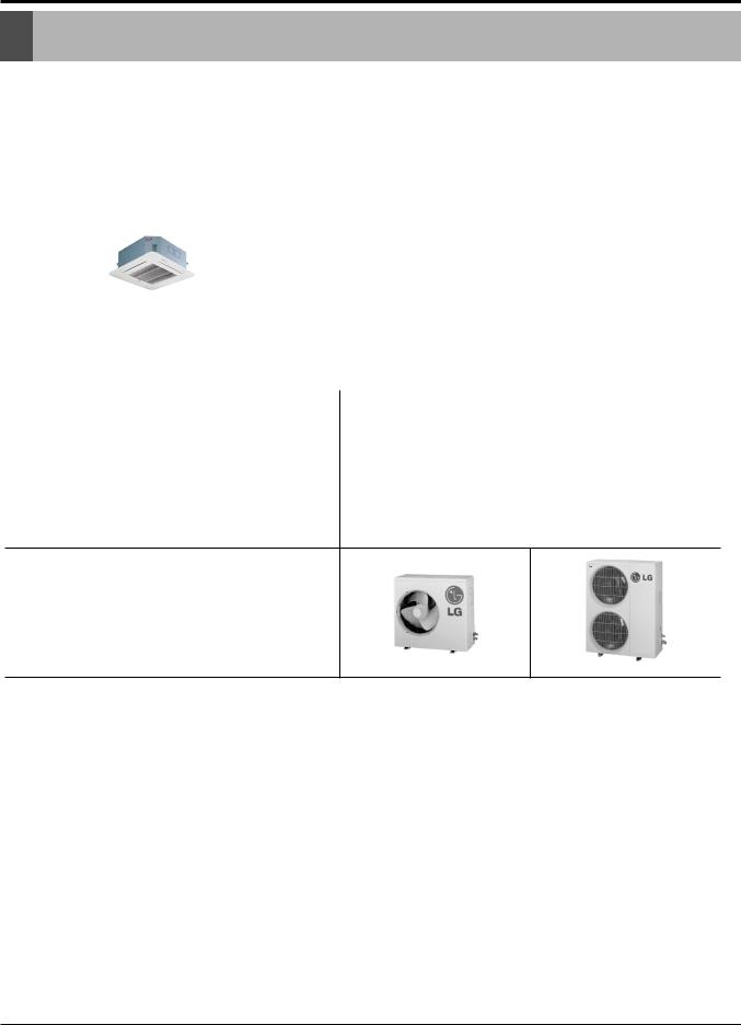
Ceiling Cassette
Air Conditioner
SERVICE MANUAL
MODEL: LCN240CP/LCU240CP
LC240CPI/LC240CPO
LCN340CP/LCU340CP
LC340CPI/LC340CPO
CAUTION
•BEFORE SERVICING THE UNIT, READ THE SAFETY PRECAUTIONS IN THIS MANUAL.
•ONLY FOR AUTHORIZED SERVICE PERSONNEL.

TABLE OF CONTENTS
Table of contents |
Page |
||
|
|
|
|
1. |
Models List ....................................................................................................................... |
3 |
|
2. |
Safety Precautions ........................................................................................................... |
4 |
|
3. |
Feature & Benefits ........................................................................................................... |
8 |
|
4. |
List of Functions ............................................................................................................. |
11 |
|
5. |
Function of Remote Control ........................................................................................... |
12 |
|
6. |
Specifications ................................................................................................................. |
14 |
|
7. |
Dimensional Drawings ................................................................................................... |
16 |
|
8. |
Wiring Diagrams............................................................................................................. |
19 |
|
9. |
Refrigerant Cycle Diagrams ........................................................................................... |
21 |
|
10. |
Installation .................................................................................................................... |
22 |
|
11. |
Trouble Shooting Guide................................................................................................ |
32 |
|
12. |
(3-Way)Valve ................................................................................................................ |
48 |
|
13. |
Electronic Control Device............................................................................................. |
52 |
|
14. |
Exploded View and Replacement Parts List ................................................................ |
53 |
|
2 Ceiling Cassette Air Conditioner
Models List
Models List
1. Model line up
1.1 Indoor units
|
|
|
|
|
Model names |
|
|
Category |
Type |
Chassis |
|
Capacity, kW(kBtu/h) |
|
||
|
|
|
|
7.03(24) |
|
9.96(34) |
|
|
|
|
|
|
|
|
|
Ceiling |
4-way |
|
|
|
|
|
|
cassette |
|
TH |
AT-C243HLF0 |
|
AT-C343HLF0 |
||
|
|
|
|
|
|
|
|
1.2 Outdoor units
Cooling only |
|
AT-C243HLF0 |
|
AT-C343HLF0 |
|
|
|
|
|
|
|
|
|
|
No. of connectable indoor units |
|
|
1 |
|
|
|
|
|
|
Total capacity index of connectable |
kW |
7.03 |
|
9.96 |
|
|
|
|
|
indoor units |
kBtu/h |
24 |
|
34 |
|
|
|||
|
|
|
|
|
Power supply |
|
1Ø, 208-230V, 60Hz |
||
Chassis
Local model name
|
|
Local Model 1 |
|
Local Model 2 |
||
Factory |
|
|
|
|
|
|
|
Indoor |
|
Outdoor |
Indoor |
|
Outdoor |
|
|
|
|
|
|
|
AT-C243HLF0 |
LCN240CP |
|
LCU240CP |
LC240CPI |
|
LC240CPO |
|
|
|
|
|
|
|
AT-C343HLF0 |
LCN340CP |
|
LCU340CP |
LC340CPI |
|
LC340CPO |
|
|
|
|
|
|
|
Service Manual 3
Safety Presautions
Safety Precautions
To prevent injury to the user or other people and property damage, the following instructions must be followed.
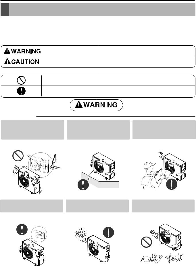
■Incorrect operation due to ignoring instruction will cause harm or damage. The seriousness is classified by the following indications.
This symbol indicates the possibility of death or serious injury.
This symbol indicates the possibility of injury or damage to properties only.
■ Meanings of symbols used in this manual are as shown below.
Be sure not to do.
Be sure to follow the instruction.
|
|
|
|
|
|
|
|
|
|
|
|
|
|
|
|
|
|
|
|
Do not use a defective or underAlways ground the product. |
Install the panel and the cover |
||
rated circuit breaker. Use this |
of control box securely. |
||
appliance on a dedicated circuit. |
|
||
•There is risk of fire or electric shock.
•There is risk of fire or electric shock.
•There is risk of fire or electric shock.
Always install a dedicated circuit and breaker.
•Improper wiring or installation may cause fire or electric shock
Use the correctly rated breaker or fuse.
•There is risk of fire or electric shock.
Do not modify or extend the power cable.
•There is risk of fire or electric shock.
4 Ceiling Cassette Air Conditioner

Safety Presautions
Do not install, remove, or re- |
Be cautious when unpacking |
install the unit by yourself |
and installing the product. |
(customer). |
|
• There is risk of fire, electric shock, |
• Sharp edges could cause injury. |
explosion, or injury. |
Be especially careful of the case |
|
edges and the fins on the con- |
|
denser and evaporator. |
Do not install the product on a |
Be sure the installation area |
defective installation stand. |
does not deteriorate with age. |
For installation, always contact the dealer or an Authorized Service Center.
•There is risk of fire, electric shock, explosion, or injury.
Do not let the air conditioner run for a long time when the humidity is very high and a door or a window is left open.
•It may cause injury, accident, or damage to the product.
•If the base collapses, the air conditioner could fall with it, causing property damage, product failure, and personal injury.
•Moisture may condense and wet or damage furniture.
Do not touch(operate) the product with wet hands.
•There is risk of fire or electrical shock.
Do not place a heater or other appliances near the power cable.
•There is risk of fire or electric shock.
Do not let electric parts of the product get wet.
•There is risk of fire, failure of the product, or electric shock.
Service Manual 5

Safety Presautions
Do not store or use flammable gas or combustibles near the product.
If strange sounds, or small or smoke comes from product. Turn the breaker off or disconnect the power supply cable.
• There is risk of fire or failure of product. |
• There is risk of electric shock or fire. |
Gasolin
Be cautious that water could not enter the product.
• There is risk of fire, electric shock, or product damage.
Install the drain hose to ensure that water is drained away properly.
• A bad connection may cause water leakage.
6 Ceiling Cassette Air Conditioner
Safety Presautions
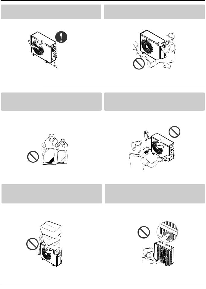
Keep level even when installing the product.
• To avoid vibration or water leakage.
Use two or more people to lift and transport the product.
• Avoid personal injury.
90˚
■ Operational
Use a soft cloth to clean. Do not use harsh detergents, solvents, etc.
• There is risk of fire, electric shock, or damage to the
Do not touch the metal parts of the product when removing the air filter. They are very sharp!
• There is risk of personal injury.
Wax
Thinner
Do not step on or put anyting on the product. (outdoor units)
• There is risk of personal injury and failure of product.
Do not insert hands or other objects through the air inlet or outlet while the product is operated.
•There are sharp and moving parts that could cause personal injury.
Service Manual 7

Features & Benefits
Features & Benefits
Environment Friendly Refrigerant :
-LG Ceiling Cassette Air Conditioners uses environment friendly refrigerant, which don't do any harm to the environment.
Plasma Air Purifier :
-It removes not only microscopic contaminants & dust, but also house mites, pollen, and pet fur to help preventing allergic diseases like asthma.It provides odor free, dust free and allergy free air.
|
|
Dust |
|
Dust particles |
|
electrode |
|
Ionizer |
discharge |
|
|
Pre-filter |
Dusts Collection |
||
|
+6.5KV |
++ |
|
Polluted |
discharge |
+ |
Purified |
|
|||
Air |
|
+ |
fresh Air |
|
|
|
|
|
|
+ |
|
Odour |
Generating |
dusts |
aluminum coated |
plasma |
|||
|
|
Odor molecule |
electrode(-) |
(3.25KV discharge)
1 2 ........ 16
Group Control :
-It enables to control as much as 16 units with the help of one wired remote controller. All the units will follow same setting of temperature & other sub functions.
Central Control :
-It enables to control 16 x 8 = 128 units with the help of 8 controllers. All units can be put on and off from one Central Room. For Setting Temperature, Fan Speed and other sub functions, access the respective LCD wired remote controller of each unit.
Jet Cool :
-In this mode, quick and fast cooling is done. Cold and high velocity air is supplied to the room till the indoor temperature reaches 18°C(64°F). The unit will continue to run in jet cool mode till the Indoor temperature reaches 18°C(64°F).
........
Main |
M |
M |
M |
M |
M |
M |
PCB |
1 |
2 |
16 |
17 |
18 |
128 |
|
Sub |
Sub |
Sub |
Sub |
Sub |
Sub |
|
1 |
2 |
16 |
17 |
18 |
128 |
Controller |
Controller |
Controller |
# 1 |
# 2 |
# 8 |
8 Ceiling Cassette Air Conditioner
Features & Benefits
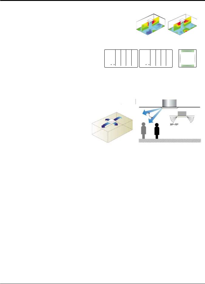
Swirl Swing
-It is the function for comfort cooling/heating operation.
-The diagonal two louvers are opened the more larger than the other louvers.
After one minute, it is opposite.
Comparison of Floor |
4- Open(Conventional) |
Swirl Swing(New) |
Temp. Distribution(20°C) |
|
|
|
|
|
|
2.4% |
|
|
|
|
100% Improved |
4.8% |
|
|
|||||||
Comparison of Air Flow Types |
|
|
|
|
|
|
|
|
|
|
|
|
|
|
|||||
4- Open(Conventional) |
|
Swirl Swing(New) |
|
|
|
|
|
|
|
Vane 2 |
|||||||||
Vane 1 |
|
|
|
|
Vane 1 |
|
|
|
|
|
|
|
|
|
|
|
|
|
|
Open |
|
Close |
Open |
Close |
Open |
Close |
|
|
|
|
|
|
|
||||||
Vane 2 |
|
|
|
|
Vane 2 |
|
|
|
|
|
|
|
|
|
|
|
|
|
|
Open |
|
Open |
Close |
Open |
Close |
Open |
|
|
|
|
|
|
|
||||||
Vane 3 |
|
|
|
|
Vane 3 |
|
|
|
|
|
|
|
Vane 1 |
|
|
|
|
|
Vane 3 |
Open |
|
Close |
Open |
Close |
Open |
Close |
|
|
|
|
|
||||||||
Vane 4 |
|
|
|
|
Vane 4 |
|
|
|
|
|
|
|
|
|
|
|
|
|
|
Open |
|
Open |
Close |
Open71 |
Close |
Open |
|
|
|
|
|
|
|
||||||
|
|
|
|
|
|
|
|
|
|
|
|
|
|
|
|
|
|
|
|
|
Time |
|
|
Time |
|
|
|
|
|
|
|
|
Vane 4 |
||||||
|
|
|
|
|
|
|
|
|
|
|
|
|
|
|
|
|
|||
Space Control
Vanes angle can be controlled by pair, considering its installation environment.
-For example direct drafts can be annoying, leading to discomfort and reduced productivity vane control helps to eliminate this problem.
-Easily controlled by wired remote control.
-Air Flow can be controlled easily regarding any space environment.
Auto Restart Operation :
-Whenever there is electricity failure to the unit, and after resumption of the power, unit will start in the same mode prior to the power failure. Memorized condition are on / off condition, operating mode, set temperature and fan speed.The unit will memorize the above conditions and start with same memorized condition.
Two Thermistor Control :
-There may be a significant difference between the temperature taken at the installed product and indoor temperature. Two thermistor control provides option to control temperature by referring any of the two temperatures. With the help of the slide switch at the back of the LCD wired remote controller, selection of the desired thermistor for controlling the unit can be done. One thermistor is in the Indoor unit & the other one is in the LCD wired remote.
Service Manual 9
Features & Benefits
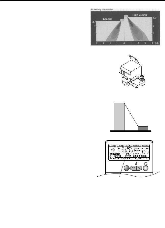
High Ceiling Operation
-According to the height of ceiling installation, it provides variability of indoor fan motor rpm. If the height of installation is low then you can adjust low rpm of indoor fan motor. On the other hand if the height of the installation is high you can adjust high rpm of indoor fan motor. Selection of speed can be done by slide switch at the back of the LCD wired remote.
ex:
Selection |
Height |
RPM |
Lower |
2.4m(7.9ft) |
700/600/500 |
|
|
|
Standard |
2.7m(8.9ft) |
750/650/550 |
Higher |
3.0m(9.8ft) |
800/700/600 |
|
|
|
Water Drain Pump :
-In some of the places natural drainage is not possible. For such places drain pump is very useful. It removes condensed water from the unit.
Time Delay Safety Function :
-It delays restarting of the compressor by three minutes thereby preventing damage to the compressor.
Zero Standby Power:
-Due to SMPS (Switching Modulation Power Supply) technology, there is almost zero power consumption in the standby mode.
Child Lock Function:
-It prevents the children or others from tampering the control buttons. Unit can be controlled by the wireless remote controller. This can be easily set by pressing timer key & Min key simultaneously. After child lock is set, pressing any key will displaye CL on the LCD for 3 seconds and all the keys will be ineffective.
Self Diagnosis Function:
-This function provides diagnosis of the unit. An error code will be displayed on the LCD wired remote controller & diagnosis can be done as per the code indication. The same is also printed on key cover of the LCD wired remote controller.
5~6W |
|
|
30m |
|
0.5W |
Others |
LG |
|
30m |
CHILD LOCK -Display
10 Ceiling Cassette Air Conditioner
List of Functions
List of Functions
• Ceiling Cassette
Category |
Function |
AT-C243HLF0 |
AT-C343HLF0 |
|
|
|
|
|
|
|
Air supply outlet |
4 |
4 |
|
|
Airflow direction control (left & right) |
X |
X |
|
|
Airflow direction control (up & down) |
Auto |
Auto |
|
|
Auto swing (left & right) |
X |
X |
|
Air flow |
Auto swing (up & down) |
O |
O |
|
Airflow steps(Fan / Cool / Heat) |
3/4/- |
3/4/- |
||
|
||||
|
CHAOS swing |
X |
X |
|
|
CHAOS wind (Auto wind) |
X |
X |
|
|
Jet cool (Power wind) |
O |
O |
|
|
Swirl wind |
O |
O |
|
|
Deodorizing filter |
X |
X |
|
Air purifying |
Plasma air purifier |
O |
O |
|
|
Prefilter(Washable) |
O |
O |
|
|
Drain pump |
O |
O |
|
Installation |
E.S.P. control |
- |
- |
|
Electric heater (Operation) |
- |
- |
||
|
||||
|
High ceiling operation |
O |
O |
|
|
Hot start |
X |
X |
|
Reliability |
Self diagnosis |
O |
O |
|
|
Soft dry operation |
O |
O |
|
|
Auto changeover |
X |
X |
|
|
Auto cleaning |
X |
X |
|
|
Auto operation(Artificial intelligence) |
O |
O |
|
|
Auto restart operation |
O |
O |
|
Convenience |
Child lock |
O |
O |
|
Forced operation |
O |
O |
||
|
||||
|
Group control |
Option |
Option |
|
|
Sleep mode |
- |
- |
|
|
Timer (On/Off) |
O |
O |
|
|
Timer (weekly) |
O |
O |
|
|
Two thermistor control |
O |
O |
|
|
Standard wired remote controller |
O |
O |
|
|
Deluxe wired remote controller |
- |
- |
|
Individual Control |
Simple wired remote controller |
- |
- |
|
Wired remote controller(for hotel use) |
- |
- |
||
|
||||
|
Wireless remote controller(simple) |
- |
- |
|
|
Wireless LCD remote controller |
PQWRHSF0 |
PQWRHSF0 |
|
|
General central control(Non LGAP) |
Option |
Option |
|
CAC Network |
Dry contact |
Option |
Option |
|
Simple central control(LGAP) |
Option |
Option |
||
Function |
||||
PDI(Power Distribution Indicator) |
Option |
Option |
||
|
||||
|
PI 485 |
Option |
Option |
|
Special Function Kit |
CTIE |
X |
X |
|
Zone control |
X |
X |
||
|
||||
Others |
Thermistor |
- |
- |
|
|
|
|
|
Note :
O : Applied, X : Not applied, – : No relation
Option: Model name & price are different according to options, and assembled in factory with main unit.
Accessory: Installed at field, ordered and purchased separately by the corresponding model name, supplied with separate package.
Service Manual 11

Function of Remote Control
Function of Remote Control
1. Wireless LCD Remote Control
 Signal transmitter
5 |
|
|
1 |
6 |
|
|
|
|
|
|
3 |
4 |
|
|
|
2 |
|
|
10 |
|
CANCEL |
|
|
|
|
9 |
|
7 |
OFF |
SET |
|
ON |
12 |
||
11 |
|
AUTO CLEAN |
|
8 |
|
|
17 |
|
°C/°F |
18 |
|
13 |
|
||
|
|
||
|
|
14 |
|
15 |
|
|
|
|
|
16 |
Flip-up door (opened)
 Operation Mode
Cooling Operation
Auto Operation
Healthy Dehumidification Operation
1. START/STOP BUTTON
Operation starts when this button is pressed and stops when the button is pressed again.
2. OPERATION MODE SELECTION BUTTON
Used to select the operation mode.
3.ROOM TEMPERATURE SETTING BUTTONS
Used to select the room temperature.
4.INDOOR FAN SPEED SELECTOR
Used to select fan speed in four steps
low, medium and high.
5. JET COOL
Used to start or stop the speed cooling.(speed cooling operates super high fan speed in cooling mode.)
6. AUTO SWING BUTTON
Used to stop or start louver movement and set the desired up/down airflow direction.
7.ON/OFF TIMER BUTTONS
Used to set the time of starting and stopping operation.
8.TIME SETTING BUTTONS
Used to adjust the time.
9.TIMER SET/CANCEL BUTTON
Used to set the timer when the desired time is obtained and to cancel the Timer operation.
10.SLEEP MODE AUTO BUTTON
Used to set Sleep Mode Auto operation.
11.AIR CIRCULATION BUTTON
Used to circulate the room air without cooling.
12.ROOM TEMPERATURE CHECKING BUTTON
Used to check the room temperature.
13.PLASMA AIR CLEAN BUTTON
Used to start or stop the plasma-purification function.
14.HORIZONTAL AIRFLOW DIRECTION CONTROL BUTTON (OPTIONAL)
Used to set the desired horizontal airflow direction.
15.RESET BUTTON
Used prior to resetting time.
16.2nd F Button
Used prior to using modes printed in blue at the bottom of buttons.
17.AUTO CLEAN (OPTIONAL)
Used to set Auto Clean mode.
18.°C/°F SWITCH BUTTON
Used to switch temperature reading from Centigrade to Fahrenheit.
The wireless remote controller do not operate the swirl mode.
12 Ceiling Cassette Air Conditioner
Function of Remote Control
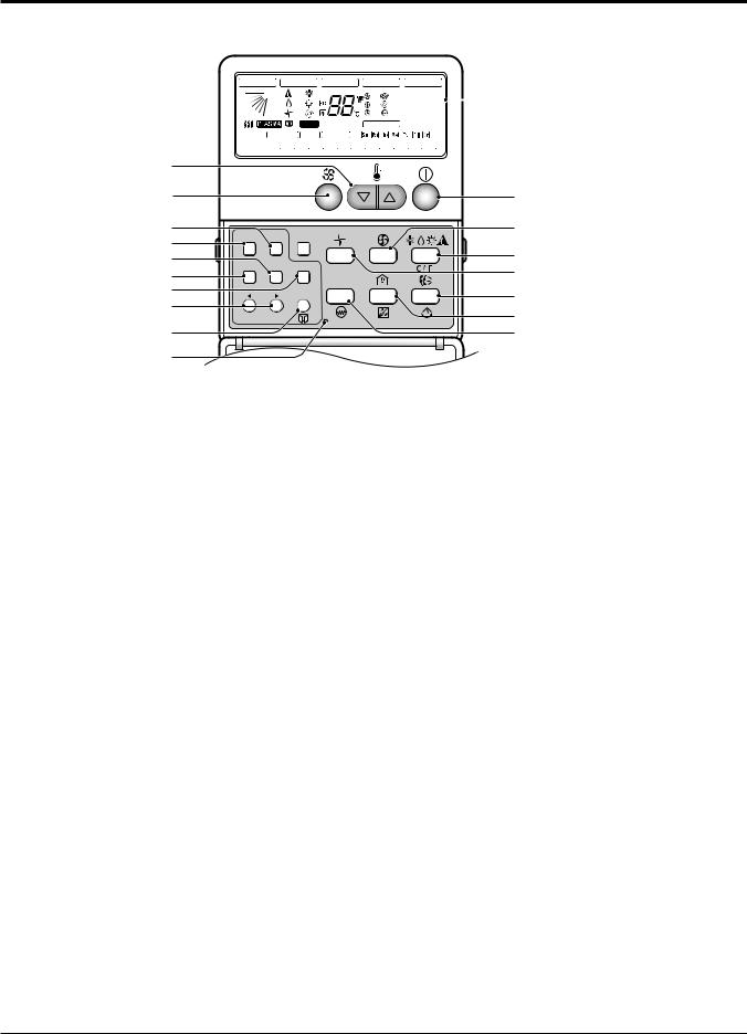
2. Wired LCD Remote Control
AUTO SWING |
OPERATION |
SET TEMP |
FAN SPEED |
SUB FUNCTION |
|
|
||||||||||||||||||||||||||||||||||||||||||||
|
|
|
|
|
|
|
|
|
|
|
|
|
|
|
|
|
|
Room Temp |
|
|
HI |
AUTO |
Heater |
Preheat |
|
1 |
||||||||||||||||||||||||
|
|
|
|
|
|
|
|
|
|
|
|
|
|
|
|
|
|
|
|
|
|
|
|
|
|
|
|
|
|
|
||||||||||||||||||||
|
|
|
|
|
|
|
|
|
|
|
|
|
|
|
|
|
|
|
|
|
|
|
|
|
|
|
|
|
|
MED |
JET |
Defrost |
Humidify |
|
||||||||||||||||
|
|
|
|
|
|
|
|
|
|
|
|
|
|
|
|
|
|
|
|
|
|
|
|
|
|
|
|
|
|
LO |
SLo |
Filter |
Out door |
|
|
|||||||||||||||
|
|
|
|
|
|
|
|
|
|
2ndF |
|
|
Time |
|
|
ZONE |
|
|
|
|
1 2 3 4 |
|
|
|
||||||||||||||||||||||||||
Timer |
Operation unit |
|
No Func |
Program set |
|
|
|
|
|
|
|
|
|
|
|
|
|
|
|
|
|
|
|
|
|
|
|
|||||||||||||||||||||||
On Off |
|
|
|
|
|
|
|
|
|
|
|
|
|
|
|
|
|
|
|
|
|
|
|
|
|
|
|
|
|
|
|
|
|
|
|
|
|
|
|
|
|
|
|
|
|
|
|
|
|
|
Set no. Time |
01 |
03 |
|
05 07 |
09 11 13 |
15 17 |
19 |
21 |
23 |
|
|
|
|
|||||||||||||||||||||||||||||||||||||
3
17
10
11
12
13
14
15
16
18
Timer Cancel 2ndF
Program Week Holiday
Plasma
Set/Clr
Hour Min
RESET
2
5
6
4
7
8
9
1 Operation display
Displays the operation conditions.
2 On/Off Button
Operation starts when this button is pressed, and stops when the button is pressed again.
3 Set Temperature Button
Used to set the temperature when the desired temperature is obtained.
4 FAN Operation Button
Used to circulate room air without cooling.
5 Fan Speed & Jet Cool Button
Used to set the desired fan speed and select jet cool mode.
6 Operation Mode Selection Button
Used to select the operation mode.
•Auto Operation Mode
•Cooling Operation Mode
•Soft Dry Operation Mode
7 Auto Swing Button
Used to swing up and down.
8 Room Temperature Checking Button
Used to check the room temperature.
9 Plasma Air Clean Button
Used to start or stop the plasma-purification function.
10 Timer Cancel Button
Used to cancel the timer.
11 Timer Set Button
Used to set the timer when the desired time is obtained.
12 Week Button
Used to set a day of the week.
13 Program Button
Used to set the weekly timer.
14 Holiday Button
Used to set a holiday of the week.
15 Time Set Button
Used to set the time of the day and change the time in the weekly timer Function.
16 Set and Clear Button
Used to set and clear the weekly timer.
17 Swirl Button
Used to select swirl swing mode.
18 Reset Button
Used to set the current time and clear the setting time.
Service Manual 13

Specifications
Specifications
|
Indoor unit type |
|
Ceilling Cassette - 4way |
|
|
|
|
|
|
|
Model |
|
AT-C243HLF0 |
AT-C343HLF0 |
|
|
(LCN240CP / LC240CPI) |
(LCN340CP / LC340CPI) |
|
|
|
|
||
|
|
|
|
|
Power supply |
|
Phase/Volts/Hz |
1 / 208-230 / 60 |
1 / 208-230 / 60 |
|
|
|
|
|
Cooling capacity |
|
kW |
7.03 |
9.96 |
|
|
|
|
|
|
|
Btu/h |
24,000 |
34,000 |
|
|
|
|
|
Heating capacity |
|
kW |
- |
- |
|
|
|
|
|
|
|
Btu/h |
- |
- |
|
|
|
|
|
Current |
Nominal running current |
A |
1.0 |
1.0 |
|
|
|
|
|
Fan |
Motor Type |
|
BLDC |
BLDC |
|
|
|
|
|
|
Fan Type |
|
Turbo Fan |
Turbo Fan |
|
|
|
|
|
|
Motor Output(W) * number of units |
50.6 * 1 |
50.6 * 1 |
|
|
|
|
|
|
|
Air flow rate (H/M/L) |
cmm |
18.4/17.0/15.6 |
24.1/22.7/21.2 |
|
|
|
|
|
|
|
cfm |
650/600/550 |
850/800/750 |
|
|
|
|
|
|
Capacitor |
mF/V |
- |
- |
|
|
|
|
|
|
Drive |
|
DC |
DC |
|
|
|
|
|
Coil |
Row * stages * FPI |
mm |
2R * 9C * 18 |
2R * 9C * 18 |
|
|
|
|
|
Dimensions |
Body |
mm(inch) |
840 * 840 * 225(331/16 * 331/16 * 87/8) |
840 * 840 * 225(331/16 * 331/16 * 87/8) |
(W*D*H) |
Decorative Panel |
mm(inch) |
950 * 950 * 30(3713/32 * 3713/32 * 13/16) |
950 * 950 * 30(3713/32 * 3713/32 * 13/16) |
Net Weight |
Body |
kg(lbs) |
26(57.3) |
26(57.3) |
|
|
|
|
|
|
Decorative Panel |
kg(lbs) |
3(6.61) |
3(6.61) |
|
|
|
|
|
Gross Weight |
Body |
kg(lbs) |
30(66) |
30(66) |
|
|
|
|
|
|
Decorative Panel |
kg(lbs) |
4(9) |
4(9) |
|
|
|
|
|
Air filter |
|
|
Long Life filter |
Long Life filter |
|
|
|
|
|
Sound Level (H/M/L) |
|
dB(A)+3 |
38/35/32 |
40/37/34 |
|
|
|
|
|
Piping Connections |
Liquid |
mm(inch) |
6.35(1/4) |
6.35(1/4) |
|
|
|
|
|
|
Gas |
mm(inch) |
12.7(1/2) |
15.88(5/8) |
|
|
|
|
|
Drain |
OD/ID |
mm(inch) |
32/25(1.26/0.98) |
32/25(1.26/0.98) |
|
|
|
|
|
Dehumidification rate |
|
l/h(pts/h) |
3.0(6.3) |
3.7(7.8) |
|
|
|
|
|
Safety Devices |
|
|
Fuse, Thermal protector for Fan motor |
|
|
|
|
|
|
Temperature sensor |
|
|
Thermistor |
Thermistor |
|
|
|
|
|
Refrigerant |
|
|
R410A |
R410A |
|
|
|
|
|
Refrigerant control |
|
|
EEV |
EEV |
|
|
|
|
|
Connectable outdoor Unit |
|
Single |
Single |
|
|
|
|
|
|
Power and Transmission interunit cable |
No.* mm2 (No. AWG) |
4 * 2.1(14) |
4 * 2.1(14) |
|
|
|
|
|
|
Note :
1.Capacities are based on the following conditions:
Cooling: - Indoor Temperature 26.7°C(80°F) DB /19.4°C(67°F) WB
-Outdoor Temperature 35°C(95°F) DB /23.9°C(75°F) WB Piping Length - Interconnecting Piping Length 7.5m(25ft)
-Level Difference of Zero.
Conversion Formula
kW = Btu/h × 0.0002931
CFM = CMM × 35.3
14 Ceiling Cassette Air Conditioner

Specifications
|
|
Outdoor Unit |
|
AT-C243HLFO |
AT-C343HLFO |
|
|
|
(LCU240CP / LC240CPO) |
(LCU340CP /LC340CPO) |
|
|
|
|
|
||
|
|
|
|
|
|
Rated Capacity |
|
Cooling |
kW |
7.03 |
9.96 |
|
|
|
Btu/h |
24,000 |
34,000 |
|
|
Heating |
kW |
- |
- |
|
|
|
Btu/h |
- |
- |
Rated Input |
|
Cooling |
kW |
2.5 |
3.6 |
|
|
Heating |
kW |
- |
- |
Energy Label |
|
|
- |
- |
|
Testing combination |
|
|
- |
- |
|
Running current |
|
Cooling |
A |
11.5 |
17 |
|
|
Heating |
A |
- |
- |
Starting current |
|
(Cooling/Heating) |
A |
24 |
38 |
Power supply |
|
Phase / Volts / Hz |
1 / 208-230 / 60 |
2 / 208-230 / 60 |
|
Power supply Cable(outdoor) |
No. * mm2(No. AWG) |
3 * 2.1(14) |
3 * 3.3(12) |
||
Power and transmission cable |
No. * mm2(No. AWG) |
4 * 2.1(14) |
4 * 2.1(14) |
||
Dimensions |
|
W * H * D |
mm(inch) |
870 * 800 * 320(341/2 * 311/2 * 1219/32) |
900 * 1160 * 370(357/16 * 4511/16 * 149/16) |
Net weight |
|
|
kg(lbs) |
73(160) |
86(190) |
Gross weight |
|
kg(lbs) |
78(172) |
93(205) |
|
Maximum number of connectable unit |
|
1 |
1 |
||
Compressor |
|
Type |
|
ROTARY |
ROTARY |
(constant) |
|
Qty * model |
|
2*GK120KAA |
GJ151KAA + GJ208KAA |
|
|
Motor Type |
|
Induction |
Induction |
|
|
Oil charge volume |
cc |
700 |
1200 |
|
|
Oil type |
|
PVE |
PVE |
Refrigerant |
|
Charge(at 7.5m(25ft)) |
g(oz) |
2100(74.1) |
2500(88.2) |
|
|
Type |
|
R410A |
R410A |
|
|
Control |
|
EEV |
EEV |
Heat Exchanger |
|
Rows * Column * FPI |
2R * 36C * 20 |
2R * 52C * 18 |
|
|
|
Defrosting method |
|
- |
- |
Fan |
|
Capacitor |
mF/Vac |
6 / 370 |
6 / 370 |
|
|
Drive |
|
Direct Drive |
Direct Drive |
|
|
Discharge Direction |
Side / Top |
Side discharge |
Side discharge |
|
|
Air flow rate |
cmm(cfm) |
51(1801) |
105(3708) |
Noise level(H) |
|
Sound press, 1m |
db (A) + 3 |
55 |
58 |
Piping connections |
|
Liquid |
mm(inch) |
6.35(1/4) |
6.35(1/4) |
|
|
Gas |
mm(inch) |
12.7(1/2) |
15.88(5/8) |
Max. piping length |
|
Main piping |
m(ft) |
30(100) |
35(115) |
Max. elevation |
|
Indoor unit - Outdoor unit |
m(ft) |
15(50) |
20(66) |
Note :
1. Capacities are based on the following conditions:
Cooling: - Indoor Temperature 26.7°C(80°F) DB /19.4°C(66.9°F) WB - Outdoor Temperature 35°C(95°F) DB /23.9°C(75°F) WB
Piping Length - Interconnecting Piping Length 7.5m(25ft)
- Level Difference of Zero.
Conversion Formula
kW = Btu/h × 0.0002931
CFM = CMM × 35.3
Service Manual 15
Dimensional Drawings
Dimensional Drawings
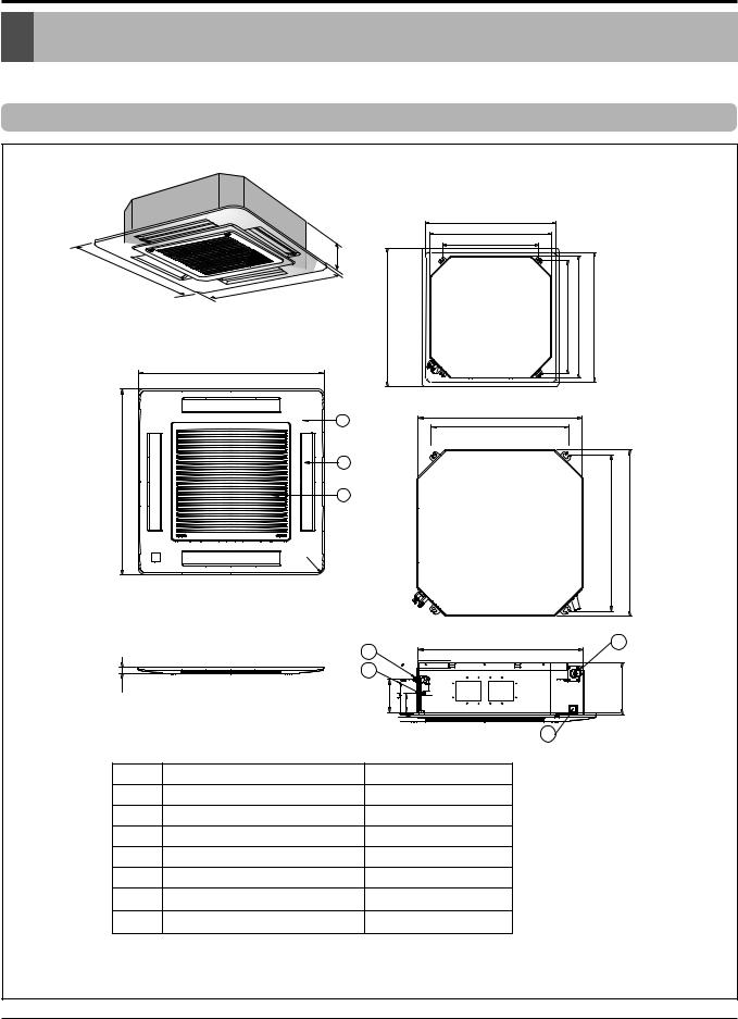
1. Indoor Units
Model No.: LCN240CP/LC240CPI/LCN340CP/LC340CPI
900(35.4) (ceiling opening)
840(33.1)
688(27.1) (hanging bolt)
225(8.9)
950(37.4) |
950(37.4) |
806(31.7)(hanging bolt) |
|
900(35.4)(ceilingopening) |
|
|
840(33.1) |
|
|||
|
950(37.4) |
|
|||
|
950(37.4) |
|
|
|
|
|
1 |
840(33.1) |
|
|
|
|
688(27.1) |
|
|
|
|
950(37.4) |
3 |
|
|
|
|
2 |
|
|
|
|
|
|
|
|
|
|
|
|
|
|
|
806(31.7) |
840(33.1) |
|
R35(1 |
|
|
|
|
|
. |
|
|
|
|
|
4) |
|
|
|
|
|
|
|
840(33.1) |
6 |
|
4 |
|
|
|
|
|
|
|
|
30(1.18) |
5 |
|
|
225(8.9) |
135(5.3) |
76(3.0) |
|
7
* mm(inch)
No. |
Part Name |
Remark |
1Decoration panel
2Air suction grille
3Air discharge grille
4Gas pipe connection
5Liquid pipe connection
6Drain pipe connection
7Power supply connection
16 Ceiling Cassette Air Conditioner
Dimensional Drawings
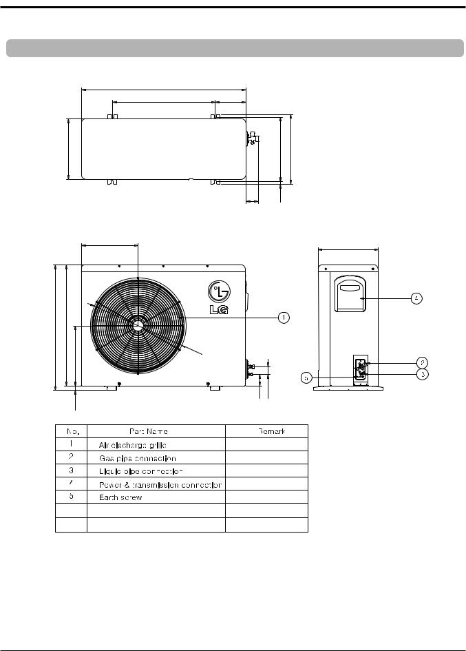
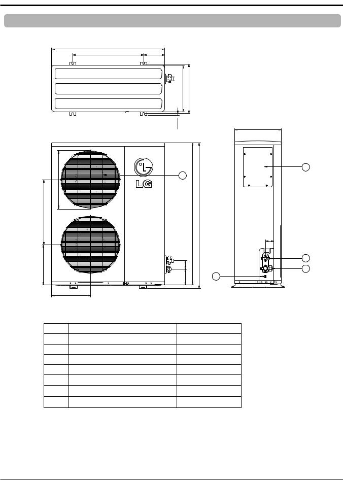
2. Outdoor Units
Model No.: LCU240CP/LC240CPO
|
870(34.3) |
|
|
|
|
|
546(21.5) |
160(6.3) |
|
|
|
|
320(12.6) |
|
|
340(13.4) |
360(14.2) |
|
|
54.6(2.1) |
10(0.4) |
|
|
|
|
|
|
||
|
333(13.1) |
|
|
|
320(12.6) |
|
|
|
|
|
|
808(31.8) |
782.5(30.8) |
|
|
|
|
|
392(15.4) |
Ø |
|
|
|
|
|
531(20. |
|
|
|
|
|
9) |
|
|
|
|
25.5(1.0) |
80(3.1) |
50(2.0) |
|
*mm(inch) |
|
|
|
|
|
|
Service Manual 17
Dimensional Drawings
Model No.: LCU340CP/LC340CPO
900(35.4) |
|
550(21.7) |
175(6.9) |
370(14.6) |
395(15.6) |
15(0.6)
|
520(20.5) |
1 |
|
|
|
|
|
565(22.2) |
|
1135(44.7) |
1165(45.9) |
273(10.7) |
124(4.9) |
80(3.1) |
|
308(12.1) |
|
370(14.6)
4
65(2.6)
3
2
5
*mm(inch)
No. |
Part Name |
Remark |
1Air discharge grille
2Gas pipe connection
3Liquid pipe connection
4Power & transmission connection
5Earth screw
18 Ceiling Cassette Air Conditioner
Wiring Diagrams
Wiring Diagrams
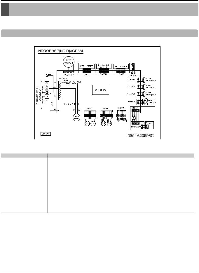
1. Indoor Unit
LCN240CP/LC240CPI/LCN340CP/LC340CPI |
|
Connector Number |
Location |
CN-POWER |
AC power supply |
CN-MOTOR |
BLDC fan motor output |
CN-DPUMP |
Drain pump output |
CN-DISP |
Display |
CN-FLOAT |
Float switch input |
CN-REMO |
Remote control |
CN-CC |
Dry-contact |
CN-ROOM |
Room sensor |
CN-PIPE1 |
In-pipe thermistor |
CN-PIPE2 |
Out-pipe thermistor |
CN-GRILL |
Elevation grille |
CN-PTC |
PTC Heater |
CN-HVB |
HVB Ass'y (Air cleaner) |
Service Manual 19
 Loading...