


LDK-20

IP LDK-20 Installation Manual
P
IIP
INSTALLATION MANUAL
L
L
D
D
K
K
2
2
0
0

IP LDK-20 Installation Manual
RREEVVIISSIIOONN HHIISSTTOORRYY
ISSUE DATE CONTENTS OF CHANGES REMARK
ISSUE 1.0
ISSUE 1.1
2005.3
2005.5
Initial Release
Add Expansion Modules and VMIBE/AAFBE

IP LDK-20 Installation Manual
TTAABBLLEE OOFF CCOONNTTEENNTTSS
■ IMPORTANT SAFETY INSTRUCTIONS ....................................................... 1
Safety requirements .................................................................................................................... 1
■ PRECAUTION................................................................................................. 2
■ THE STRUCTURE OF MANUAL ................................................................... 3
SECTION 1. INTRODUCTION................................................................................ 4
1.1 The IP LDK-20 System highlights......................................................................................... 4
1.2 System Connection Diagram ............................................................................................... 4
1.3 System Components ............................................................................................................ 5
1.4 Specifications ....................................................................................................................... 6
1.4.1 General specifications.............................................................................................................. 6
1.4.2 System Capacity ...................................................................................................................... 7
SECTION 2. KSU INSTALLATION ......................................................................... 8
2.1 Pre-Installation...................................................................................................................... 8
2.1.1 Safety installation instructions ................................................................................................. 8
2.1.2 Installation precautions ............................................................................................................ 8
2.1.3 Wiring precautions ................................................................................................................... 8
2.2 KSU Installation .................................................................................................................... 9
2.2.1 Unpacking ................................................................................................................................ 9
2.2.2 KSU exterior and dimension ................................................................................................... 10
2.2.3 KSU with expansion module exterior and dimension............................................................. 11
2.2.4 Opening and closing the front cover......................................................................................12
2.2.5 Frame ground connection ...................................................................................................... 14
2.2.6 Power Supply Unit (PSU) installation .................................................................................... 15
2.2.7 External backup batteries installation .................................................................................... 16
2.2.8 KSU mounting ........................................................................................................................ 17
SECTION 3. BOARD INSTALLATION.................................................................. 20
3.1 Installation of the Boards.................................................................................................... 20
3.2 MBUB (Main Board Unit) ................................................................................................... 21
3.2.1 Modular Jack(MJ1~MJ3) Pin Assignment............................................................................. 23
3.3 Installation of the CO Line Board ....................................................................................... 29
3.3.1 LCOB (CID Loop Start CO line Interface Board)................................................................... 29
3.3.2 STIB (Basic Rate Interface Board: Selectable S/T interface) ............................................... 32
3.3.3 CBIB (CID Loop Start CO line + Basic Rate Interface Board) .............................................. 36
3.4 Installation of the Extension Board .................................................................................... 39
3.4.1 DTIB4 (Digital Terminal Interface Board) .............................................................................. 39
3.4.2 DTIB8 (Digital Terminal Interface Board) .............................................................................. 40
3.4.3 SLIB4 (Single Line Interface Board) ......................................................................................41
3.4.4 SLIB8 (Single Line Interface Board) ......................................................................................42
3.5 Other Board Installations.................................................................................................... 43
3.5.1 VMIBE (Voice Mail Interface Board Enhanced) .................................................................... 43
3.5.2 AAFBE(Auto Attendant Function Board Enhanced) ............................................................. 44
3.5.3 LANU (LAN interface Unit)..................................................................................................... 45
3.5.4 MODU (MODEM function Unit) ............................................................................................. 46
SECTION 4. EXPANSION MODULE INSTALLATION .......................................... 47
i

IP LDK-20 Installation Manual
4.1 Unpacking............................................................................................................................ 47
4.2 Opening and closing the front cover ................................................................................... 48
4.2.1 Opening the front cover .......................................................................................................... 48
4.2.2 Closing the front cover ............................................................................................................ 49
4.3 Opening and closing the front cover ................................................................................... 50
4.3.1 Connecting Expansion Module to KSU .................................................................................. 50
4.3.2 Wall mounting ......................................................................................................................... 51
4.3.3 Rack Mounting ........................................................................................................................ 52
4.4 External backup batteries connection................................................................................. 54
4.5 VOIM (Voice over Internet Protocol Interface Module) installation.................................... 55
Various switches and connectors functions .................................................................................... 56
4.5.1 Pin assignment........................................................................................................................ 57
4.5.2 VOIU(Voice over Internet Protocol Interface Unit) ................................................................. 58
4.6 SLIM(SLT Interface Module) Installation ............................................................................ 59
4.6.1 Pin assignment........................................................................................................................ 59
4.7 DTIM(DKT Interface Module).............................................................................................. 60
4.7.1 Pin assignment........................................................................................................................ 60
SECTION 5. TERMINAL CONNECTION.............................................................. 61
5.1 Terminal Models ................................................................................................................. 61
5.2 Terminal Cabling Distance................................................................................................. 62
5.3 Keyset Connection ............................................................................................................. 63
5.3.1 Digital Keyset ......................................................................................................................... 63
5.3.2 SLT......................................................................................................................................... 63
5.4 Connecting Additional Terminals ....................................................................................... 64
5.4.1 External Music Source wiring ................................................................................................ 64
5.4.2 Relay Contacts....................................................................................................................... 64
5.4.3 External Paging wiring ........................................................................................................... 64
5.4.4 Alarm Detection wiring ........................................................................................................... 64
SECTION 6. STARTING THE IPLDK-20 SYSTEM .............................................. 65
6.1 Before Starting the IP LDK-20 System .............................................................................. 65
6.2 Basic Preprogramming.......................................................................................................65
6.2.1 DKTU (Station 10) programming ........................................................................................... 65
6.2.2 Entering programming mode ................................................................................................. 67
6.2.3 Pre-programming ................................................................................................................... 68
SECTION 7. TROUBLESHOOTING ...................................................................... 76
ii

IP LDK-20 Installation Manual Introduction
■ Important Safety Instructions
Safety requirements
When using your telephone equipment, basic safety precautions should always be followed to reduce the risk of fire,
electric shock and other personal injury, including the following:
• Please read and understand all instructions.
• Follow all warnings and instructions marked on the product.
• Unplug this product from the wall outlet before cleaning. Just a damp cloth should be used for cleaning; do not
use liquid or aerosol cleaners.
• Do not use this product near water, such as in a bathtub, wash bowl, kitchen sink, or laundry tub, in a wet
basement, or near a swimming pool.
• Do not place this product on an unstable cart, stand, or table. The product may fall, causing serious damage to
the product or personal injury.
• Slots and openings in the KSU and the back or bottom are provided for ventilation, to protect it from overheating,
these openings must not be blocked or covered. The openings should never be blocked by placing the product on
a bed, sofa, rug, or other similar surface. This product should never be placed near or over a radiator or other
heat source. This product should not be placed in a built-in installation without proper ventilation.
• This product should be operated only from the type of power source indicated on the product label. If you are not
sure of the type of power supply to your home, consult your dealer or local power company.
• Do not allow anything to rest on the power cord. Do not locate this product where the cord could be abused by
people walking on it.
• Do not overload wall outlets and extension cords as this can result in the risk of fire or electric shock.
• Never push objects of any kind into this product through KSU slots or connectors as they may touch dangerous
voltage points or short out parts that could result in a risk of fire or electric shock. Never spill liquid of any kind on
the product.
• To reduce the risk of electric shock, do not disassemble this product. Instead, take it to a qualified person when
service or repair work is required. Opening or removing covers may expose you to dangerous voltages or other
risk. Incorrect reassemble can cause electric shock when the appliance is subsequently used.
• Unplug this product from the wall outlet and refer servicing to qualified service personnel under the following
conditions:
- When the power supply cord or plug is damaged or frayed.
- If liquid has been spilled into the product.
- If the product has been exposed to rain or water.
- If the product does not operate normally by following the operating instructions. Adjust only those controls that
are covered by the operating instructions because improper adjustment of other controls may result in
damage and will often require extensive work by a qualified technician to restore the product to normal
operation.
- If the product has been dropped or the KSU has been damaged.
- If the product exhibits a distinct change in performance.
• Avoid using a telephone during an electrical storm. There may be a remote risk of electric shock from lightning.
• In the event of a gas leak, do not use the telephone near the leak.
1

IP LDK-20 Installation Manual Introduction
■ Precaution
• Keep the system away from heating appliances and electrical noise generating devices such as fluorescent
lamps, motors and televisions. These noise sources can interfere with the performance of the IP LDK-20
System.
• This system should be kept free of dust, moisture, high temperature (more than 40 degrees) and vibration,
and should not be exposed to direct sunlight.
• Never attempt to insert wires, pins, etc. into the system. If the system does not operate properly, the trouble
has been repaired by an authorized LG service center.
• Do not use benzene, paint thinner, or any abrasive powder to clean the KSU. Wipe it with a soft cloth.
CAUTION
• This system should only be installed and serviced by qualified service personnel.
• When a failure occurs which exposes any internal parts, disconnect the power supply cord immediately and
return this system to your dealer.
• To prevent the risk of fire, electric shock or energy hazard, do not expose this product to rain or any type of
moisture.
• To protect PCB from static electricity, discharge body static before touching connectors and/or components
by touching ground or wearing a ground strap.
WARNING
Danger of explosion if battery is incor r ectly replaced. Replace only with the same or equ iv ale nt ty pe rec omme nd ed by
the manufacturer. Dispose of used batteries according to the manufacturer’s instructions.
2

IP LDK-20 Installation Manual Introduction
■ The Structure of Manual
This installation manual is designed to provide as general information for the IP LDK-20 System. It provides
instructions for installing the hardware, and programming the IP LDK-20 System using keyset. This manual contains
the following sections:
Section 1. Introduction
Provides general information on the IP LDK-20 System, including the system specifications and capacity.
Section 2. KSU Installation
Describes detailed instructions for planning the installation site and procedures to install the IP LDK-20 System.
Section 3. Board Instal lat ion
Describes general information and detailed instructions for installing boards and add-on boards.
Section 4. Expansion Module Installation
Describes the kinds of terminals, maximum distance, and the other device connections for the terminal.
Section 5. Terminal Connection
Describes the kinds of terminals, maximum distance, and the other device connections for the terminal.
Section 6. Starting the IP LDK -20 Sy st em
Provides general information for starting the system and basic preprogramming.
Section 7. Troubleshooting
Provides information on the IP LDK-20 System and troubleshooting.
3
IP LDK-20 Installation Manual Introduction
SECTION 1. INTRODUCTION
1.1 The IP LDK-20 System highlights
Features of the IP LDK-20 System include:
• Flexible architecture
• Optional LAN Interface
• Stable & enhanced voice features
• Simple installation & efficient system management
- Remote admin through BRI connection
- Remote admin through PSTN modem
- Remote admin through LAN connection
• Value-added features
- Distinctive voice mail
- CID (CO & SLT)
- VOIP Service
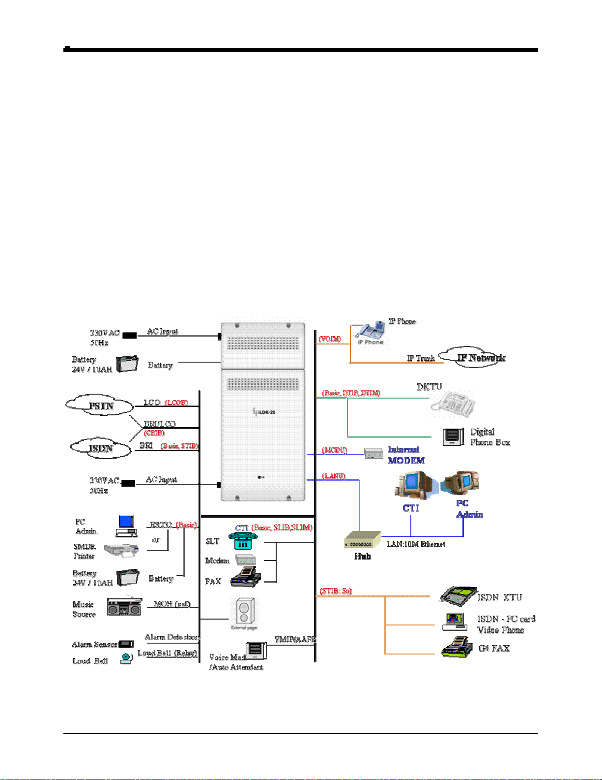
1.2 System Connection Diagram
Figure 1.2 IP LDK System Connection Diagram
4

IP LDK-20 Installation Manual Introduction
1.3 System Components
ITEM OPTION BOARD DESCRIPTION
Main
Board
CO Line
Boards
Extension
Boards
Other
Boards
Expansion
Modules
KSU
PSU
Key Service Unit
Power Supply Unit, 90W
MBUB
LCOB
PRU4 Polarity Reversal detection Unit
CBIB
STIB
DTIB4
DTIB8
SLIB4
SLIB8
VMIBE
AAFBE
LANU
MODU
VOIM
SLIM
DTIM
Voice over Internet protocol interface module (4 channels)
Main Board Unit (2BRI, 4DKT, 2DKT/SLT, and 2SLT)
CO boards Central Office Line interface boards (LCOB, STIB,CBIB)
EXT boards Extension boards (DTIB, SLIB)
Loop Start CO Interface, 4 lines
PRCPTU4 Polarity Reversal & Call Progress Tone detection Unit
CPCU4
PRU2 Polarity Reversal detection Unit
PRCPTU2 Polarity Reversal & Call Progress Tone detection Unit
CPCU2
ISDN Basic Rate (S/T) Interface Board, 2 lines (4channels)
Digital Terminal Interface Board, 4 ports
Digital Terminal Interface Board, 8 ports
SLT Interface (+36V Feed) Board, 4ports
Enhanced Voice Mail Interface Board, 4 channels
Enhanced Auto Attendant Function Board, 3 channels
LAN interface Unit (10Mbase-T only)
MODEM unit (33Kbps)
VOIU Voice over Internet protocol interface unit.(4 channels)
SLT Interface (+36V Feed) module, 8ports
Digital Terminal Interface module, 8 ports
Caller-ID(FSK), Polarity Reversal & Call Progress Tone
detection Unit
Loop Start CO Interface, 2 lines
Basic Rate(Only T) Interface Board, 1 line (2 channels)
Caller-ID(FSK), Polarity Reversal & Call Progress Tone
detection Unit
SLT Interface (+36V Feed) Board, 8ports
5

IP LDK-20 Installation Manual Introduction
1.4 Specifications
1.4.1 General specifications
ITEM DESCRIPTION SPECIFICATION
PSU
AC Adaptor
Battery Backup
External Relay Contact 1A @ 30 Volt DC
Music Source Input 0 dBm @ 600ohm
External Paging Port 0 dBm @ 600ohm
Ring Detect Sensitivity 30Vrms @ 16-55Hz
DTMF Dialing
Operating Temperature
Environment Humidity 0-80%(non condensing)
LANU
MODU Analog modem
VOIM
AC Voltage Input 230 +/-10% Volt AC @47-63Hz
AC Power 90W
AC Input Fuse 1.25A @ 250Volt AC
DC Output Voltage +5, -5, +30Volt DC
AC Voltage Input 230 +/-10% Volt AC @47-63Hz
AC Input Fuse 1A @ 250Volt AC
DC Output Voltage 48Volt DC
Input Voltage 24 Volt DC
Battery Fuse 5.0A @ 250Volt AC
Charging Current Max. 100mA
Battery Load Current Max. 3A (with Analog CO or ISDN CO)
Frequency Deviation Less than +/-1.8%
Signal Rise Time Max.5ms
Tone Duration, on time Min.50ms
Inter-digit Time Min.30ms
Pulse Rate 10 PPS Pulse Dialing
Break/Make Ratio 60/40% or 66/33%
0(℃)-40(℃)
KSU 260mm(W)*410mm(H)*86mm(D) Dimension
Expansion Module 260mm(W)*145mm(H)*86mm(D)
KSU 2.5Kg Weight
Expansion Module DTIM/SLIM: 1.16Kg, VOIM: 0.58Kg
LAN Interface 10 Base -T Ethernet (IEEE 802.3)
Speed 10 Mbps
Duplex Half duplex or Full duplex (Auto-Negotiation)
Bell, ITU-T, V.34, V.32BIS, V.90
300bps up to 33Kbps speed rate
Automatic rate negotiation
LAN Interface 10 / 100 Base-T Ethernet (IEEE 802.3)
Speed 10 Mbps or 100 Mbps (Auto-Negotiation)
Duplex Half Duplex or Full Duplex (Auto-Negotiation)
VOIP Protocol H.323 Revision 2
Voice Compression G.711/G.726/G729/G.723.1
Voice/Fax Switching T.38
Echo cancellation G.165
6

IP LDK-20 Installation Manual Introduction
1.4.2 System Capacity
DESCRIPTION CAPACITY/BOARD TOTAL
Time Slots 96
4/MBUB(BRI)
CO Line Ports
Max direct Station connections
Max LAN port 1/LANU 1
Max MODEM Channel 1/MODU 1
Attendant Positions 5/System
Intercom Links Non-blocking
Paging
- All Call
- Internal
Station Speed Dial 100/station, 24 digits each 500
System Speed Dial 24 digits each 500
Last Number Redial 10 32 digits
CO Line Group 8 8
Station Group 10 10
Conference 3-Party no limit
Music Source Input 1/MBUB 1
External Paging 1/MBUB 1
External Control Contact 2/MBUB 2
Alarm Input 1/MBUB 1
RS-232C Port 1/MBUB 1
DTMF Receiver 3/MBUB, 2/SLIB, 2/SLIM 7
Auto Fax detection 1/MBUB 1
4/LCOB or 4/STIB
8/VOIM
8/MBUB
8/DTIB or 8/SLIB
8/DTIM, 8 SLIM, or 8/VOIM
(Analog CO, ISDN BRI and/or IP trunk)
Max. 16
Max. 24
1 zone
5 zones
7

IP LDK-20 Installation Manual KSU Installation
SECTION 2. KSU INSTALLATION
2.1 Pre-Installation
Please read the following guidelines concerning installation and connection before installing the IP LDK-20 System.
Be sure also to comply with applicable local regulations.
2.1.1 Safety installation instructions
When installing the telephone wiring, basic safety precautions should always be followed to reduce the risk of fire,
electric shock and personal injury, including the following:
• Never install the telephone wiring during a lightning storm.
• Never install the telephone jack in wet locations unless the jack is specifically designed for wet locations.
• Never touch uninsulated telephone wires or terminals unless the telephone line has been disconnected at the
network interface.
• Use caution when installing or modifying telephone lines.
• Anti-static precautions should be taken during installation.
2.1.2 Installation precautions
The IP LDK-20 System is designed for wall mounting or a free-standing rack. Avoid installing in the following places.
• In direct sunlight and hot, cold, or humid places. Temperature range : 0 to 40℃
• Places where shocks or vibrations are frequent or strong.
• Dusty places, or places where water or oil may come into contact with the system.
• Near high-frequency generating devices such as sewing machines or electric welders.
• On or near computers, fax machines, or other office equipment, as well as microwave ovens or air conditioners.
• Do not obstruct the area around the IP LDK-20 System (for reasons of maintenance and inspection)
• Do not block the openings on the top of the IP LDK-20 System.
• Do not stack up the optional service boards.
2.1.3 Wiring precautions
Be sure to follow these precautions when wiring.
• Do not wire the telephone cable in parallel with an AC power source, such as a computer, fax machine, etc. If the
cables are run near those wires, shield the cables with metal tubing or use shielded cables and ground the shields.
• If the cables are run on the floor, use protectors to prevent the wires from being stepped on. Avoid wiring under
carpets.
• Avoid using the same power supply outlet for computers, fax machines, and other office equipment to avoid
induction noise interruption when using the IP LDK-20 near other machines.
• The power and battery switches of the IP LDK-20 System must be OFF during wiring. After the wiring is
completed, the power switch may be turned ON.
• Incorrect wiring may cause the IP LDK-20 System to operate improperly.
• If an extension does not operate properly, disconnect the telephone from the extension line and then re-connect,
or turn the power of the IP LDK-20 System OFF and ON again.
• Use twisted pair cable for CO line connection.
8
IP LDK-20 Installation Manual KSU Installation
2.2 KSU Installation
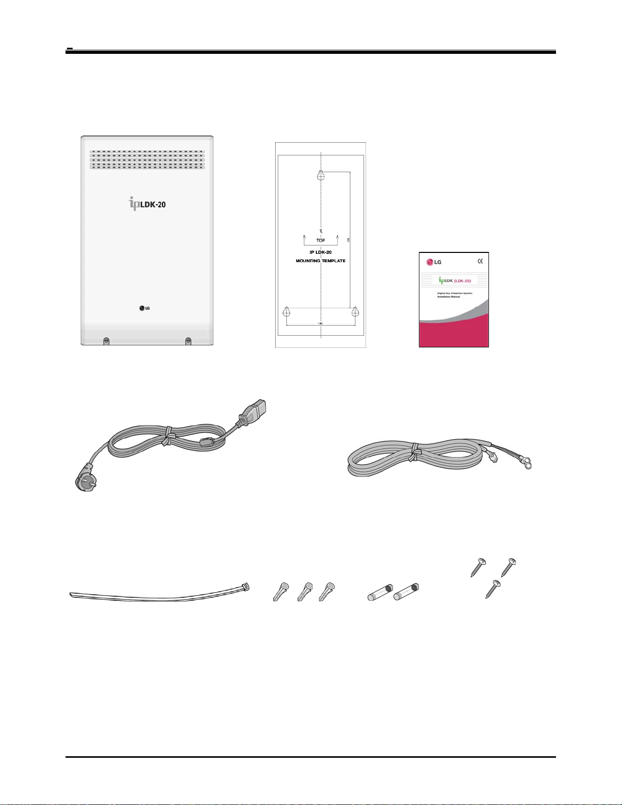
2.2.1 Unpacking
Open the box and verify the items shown in Figure 2.2.1 are included:
Key service unit
Power cord
Tie cable Anchor plug
Mounting template
Figure 2.2.1 Unpacking
Battery cable
Fuse
Manual
Screw
9
IP LDK-20 Installation Manual KSU Installation
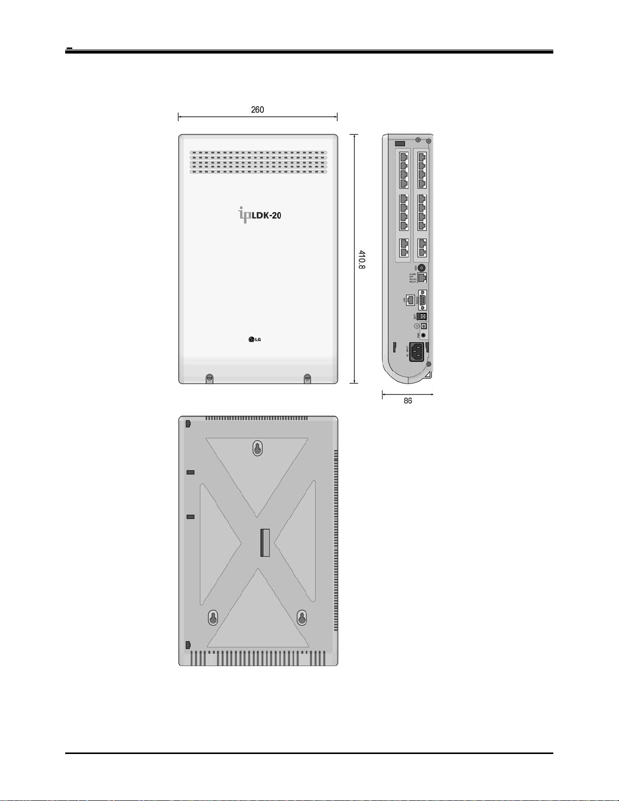
2.2.2 KSU exterior and dimension
Figure 2.2.2 shows the exterior and dimensions of the KSU:
Figure 2.2.2 KSU exterior and dimension
10
IP LDK-20 Installation Manual KSU Installation
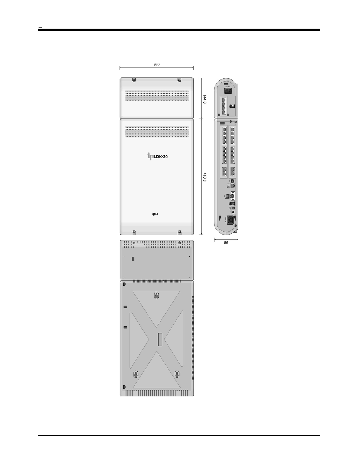
2.2.3 KSU with e xpansion modu le exterior and dimension
Figure 2.2.3 shows the exterior and dimensions of the KSU:
Figure 2.2.3 KSU with expansion module exterior and dimension
11
IP LDK-20 Installation Manual KSU Installation
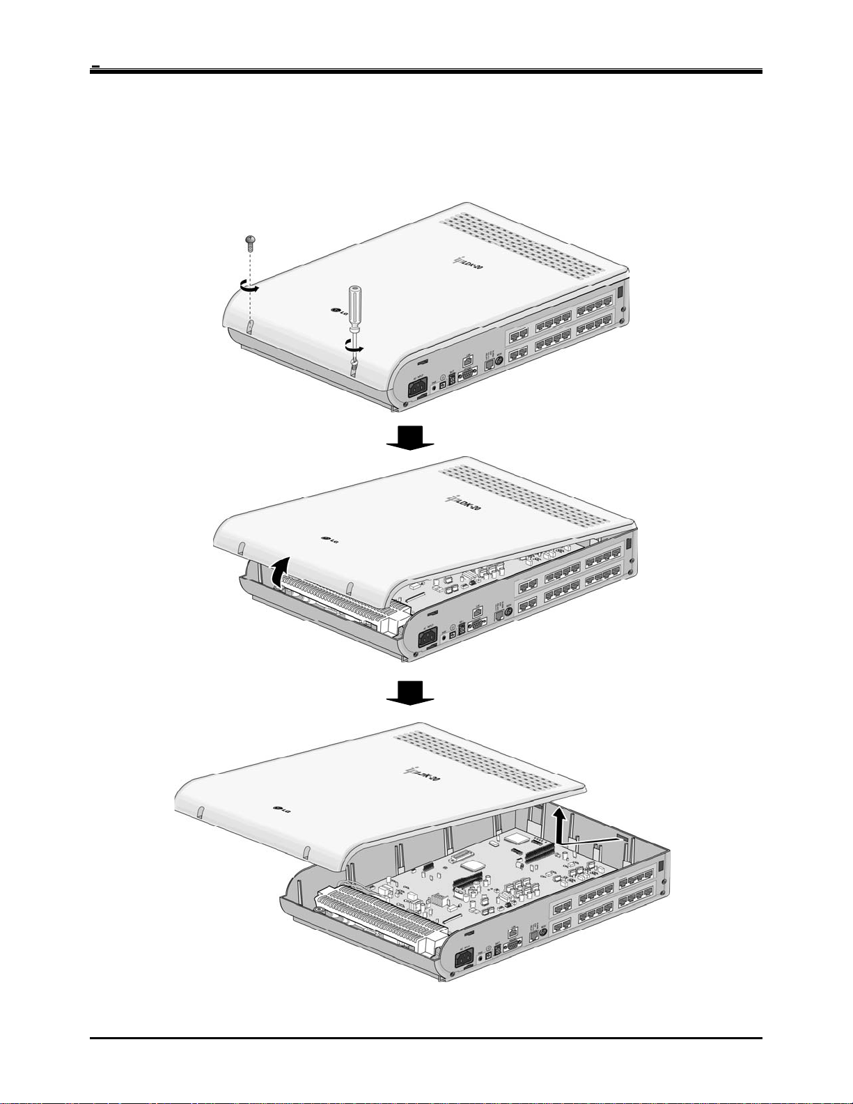
2.2.4 Opening and closing the front cover
2.2.4.1 Opening the front cover
1. Turn the screw counter-clockwise to loosen as shown in Figure 2.2.4.1.
2. Lift the front cover in the direction of the arrow as shown:
Figure 2.2.4.1 Opening the front cover
12
IP LDK-20 Installation Manual KSU Installation
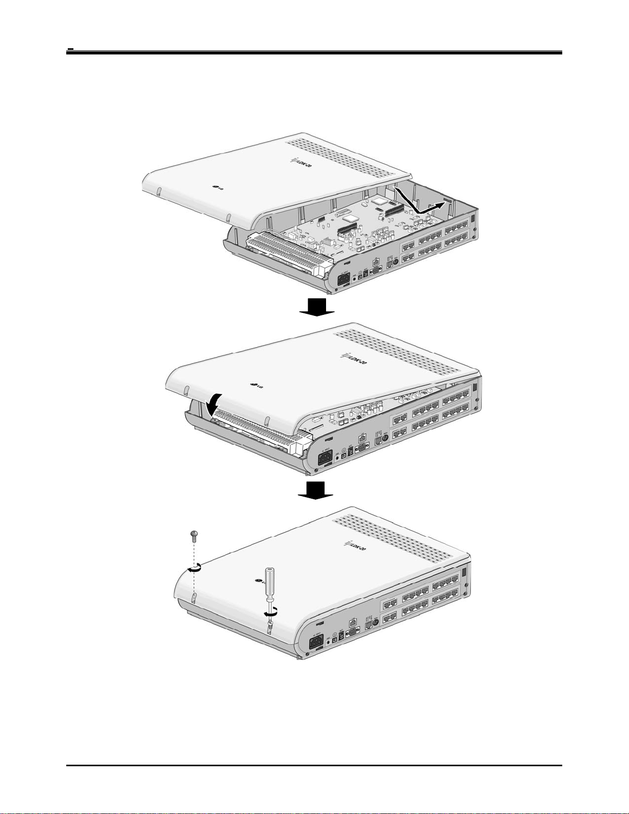
2.2.4.2 Closing the front cover
Insert the front cover into the slot on the KSU as show in Figure 2.2.4.2.
Then put the front cover down on the KSU in the direction of the arrow, as shown.
Turn the screws clockwise to tighten, as in the Figure.
Figure 2.2.4.2 Closing the front cover
※
NOTE
For safety reasons, close the front cover and tighten the screws prior to operating the IP LDK-20 System.
13
IP LDK-20 Installation Manual KSU Installation
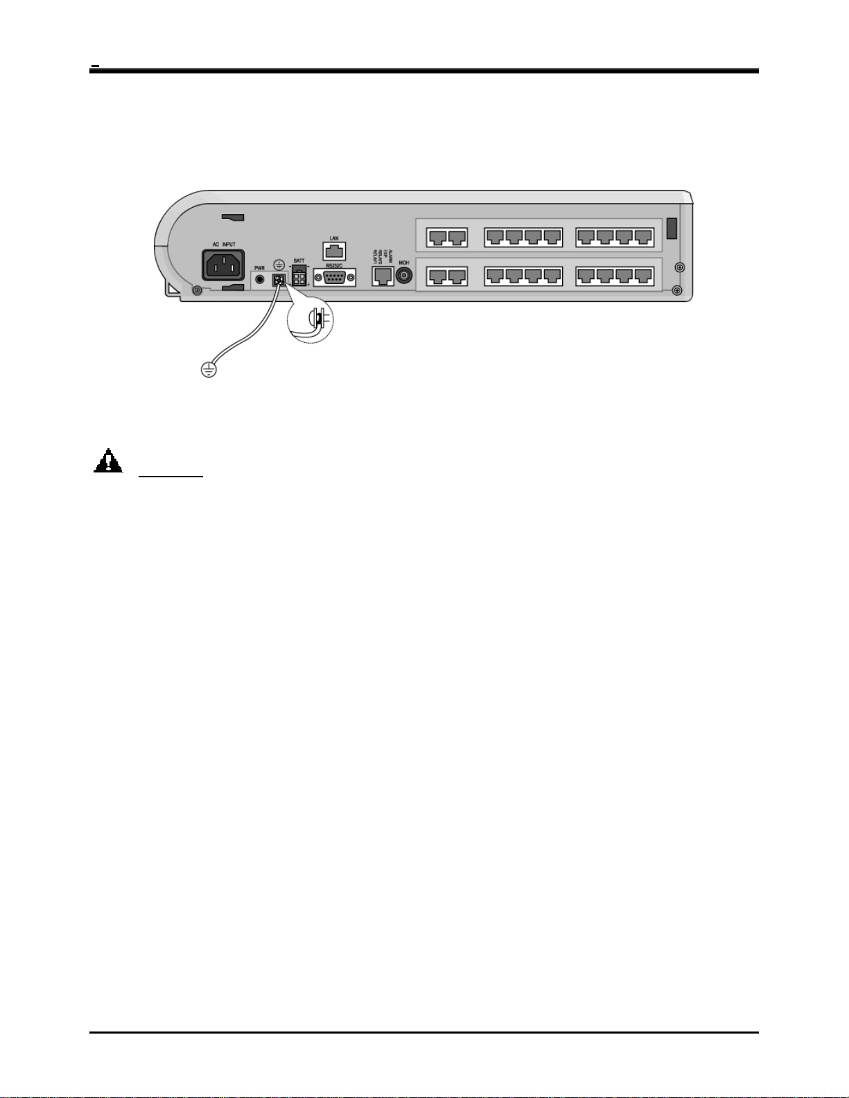
2.2.5 Frame ground connection
It is very important the frame of the IP LDK-20 system is grounded:
1. Turn the screw counter-clockwise to loosen. Then insert the grounding wire.
2. Tighten the screw. Then connect the grounding wire to ground source as shown in Figure 2.2.5.
Figure 2.2.5 Grounding the KSU
CAUTION
• The equipment should be connected to a socket-outlet with a protective ground connection.
• For ground wire, green-and-yellow insulation is required, and the cross-sectional area of the conductor must
be more than UL 1015 AWG# 18 (1.0mm). It is recommended that the ground wire be shorter than 1 meter
(3.28 feet).
• Proper grounding is very important to protect the IP LDK-20 system from external noise or to reduce the risk
of electrocution in the event of lightning strike.
• Be sure to comply with applicable local regulations.
14
IP LDK-20 Installation Manual KSU Installation
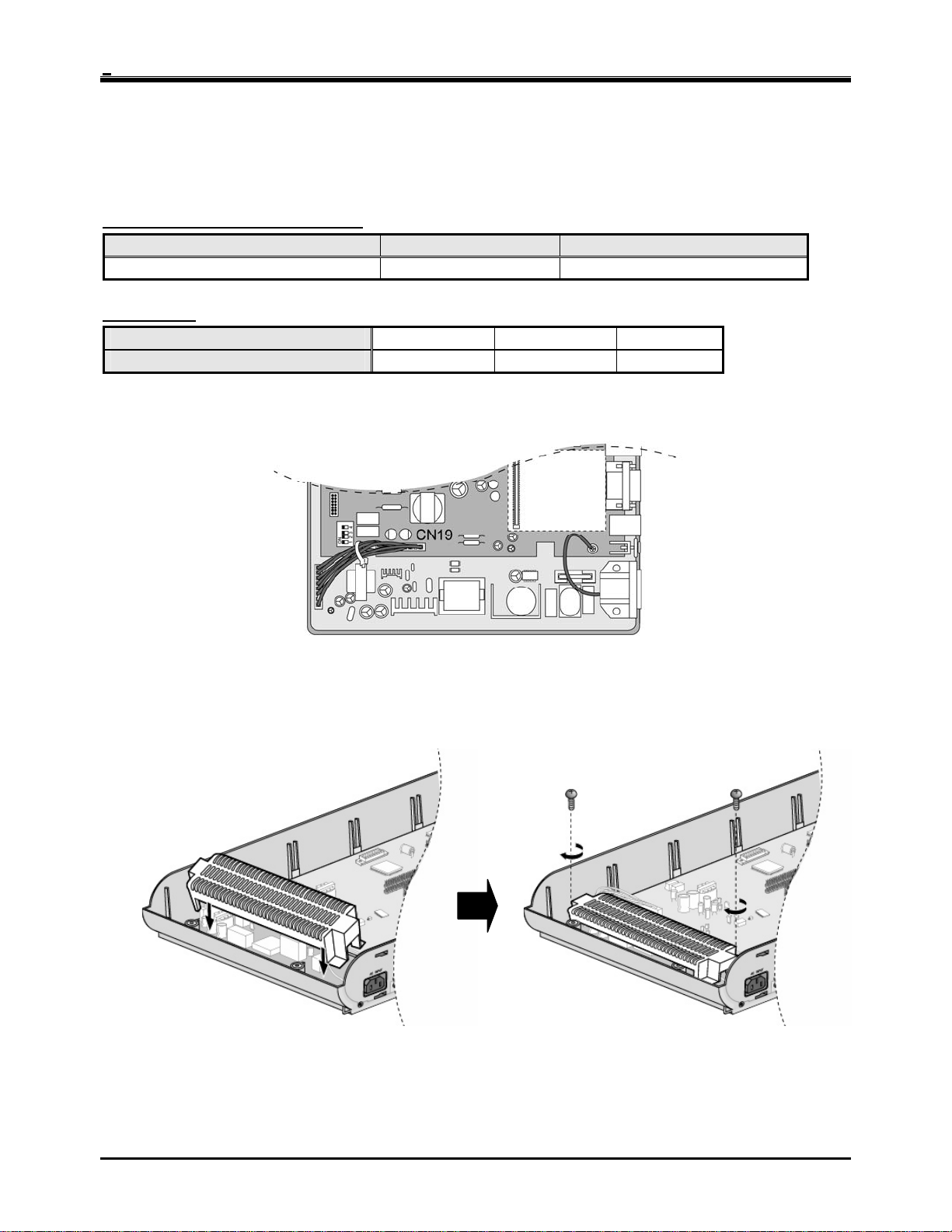
2.2.6 Power Sup ply Unit (PSU) installation
Before installation, make sure that the KSU not plugged into an outlet. The PSU is located at the left-most area of the
KSU, and is capable of providing three kinds of power sources to MBUB through the 7PIN connector, CN19 (refer to
the following table).
The AC Input Voltage and Fuse Rating
RANGE OF INPUT VOLTAGE CONNECT TO FUSE RATINGS
207V AC - 253V AC CN19 on the MBUB 1.25A @250V
PSU Capacity
1. To secure the wire of PSU as shown in Figure 2.2.6a, tie the wire with the cable tie provided.
2. Place the PSU cover on the PSU as shown in Figure 2.2.6b. Then turn the screws clockwise to tighten, and secure.
PSU TYPE +5V DC -5V DC +30V DC
PSU (SMPS)
3.0A 100mA 1.9A
Figure 2.2.6a PSU Installation
Figure 2.2.6b PSU Installation
15
IP LDK-20 Installation Manual KSU Installation
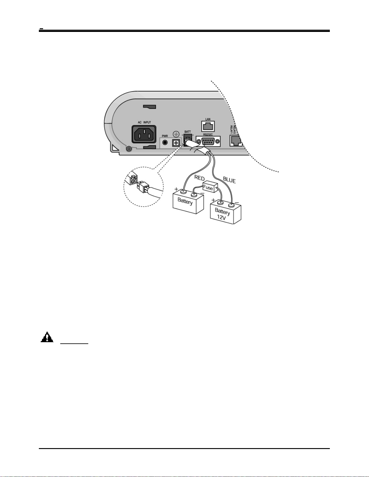
2.2.7 External backup batteries installation
In case of power failure, the external backup batteries automatically maintain uninterrupted power for the IP LDK-20
system. The external batteries must provide 24 Volts DC. This is generally accomplished by connecting two 12 Volt
batteries in a series arrangement.
Figure 2.2.7 External Back Up Battery Installation
※
Note : The cable for connecting the batter y is supp lied with the KSU .
Operation of the batteries is controlled by the MBUB. This IP LDK-20 MBUB will provide charging current to the
batteries during normal AC power operation at a maximum of about 100mA. During battery operation, the battery
operation of MBUB will be stopped if the AC power re-applied or the battery voltage is too low to maintain full-system
operation.
The external batteries can maintain system operation as needed depending on several elements such as, battery
charge status, condition and capacity of the batteries, and system configuration (number of station ports).
CAUTION
• It is recommended to use a fuse (5A @250V) between battery and system.
• Recommended battery capacity is 24V/10AH MF battery; the IP LDK-20 system should operate more than 3
hours with batteries that are in good condition.
• Carefully check the battery polarity with cable colors (RED and BLUE) when connecting the battery to the
system.
• Make sure that you do not short-out the external backup batteries or cables.
• There is a danger of explosion if external backup batteries are incorrectly replaced. Replace only with the
same or equivalent type recommended by the manufacturer. Dispose of used batteries according to the
manufacturer’s instructions.
16
IP LDK-20 Installation Manual KSU Installation
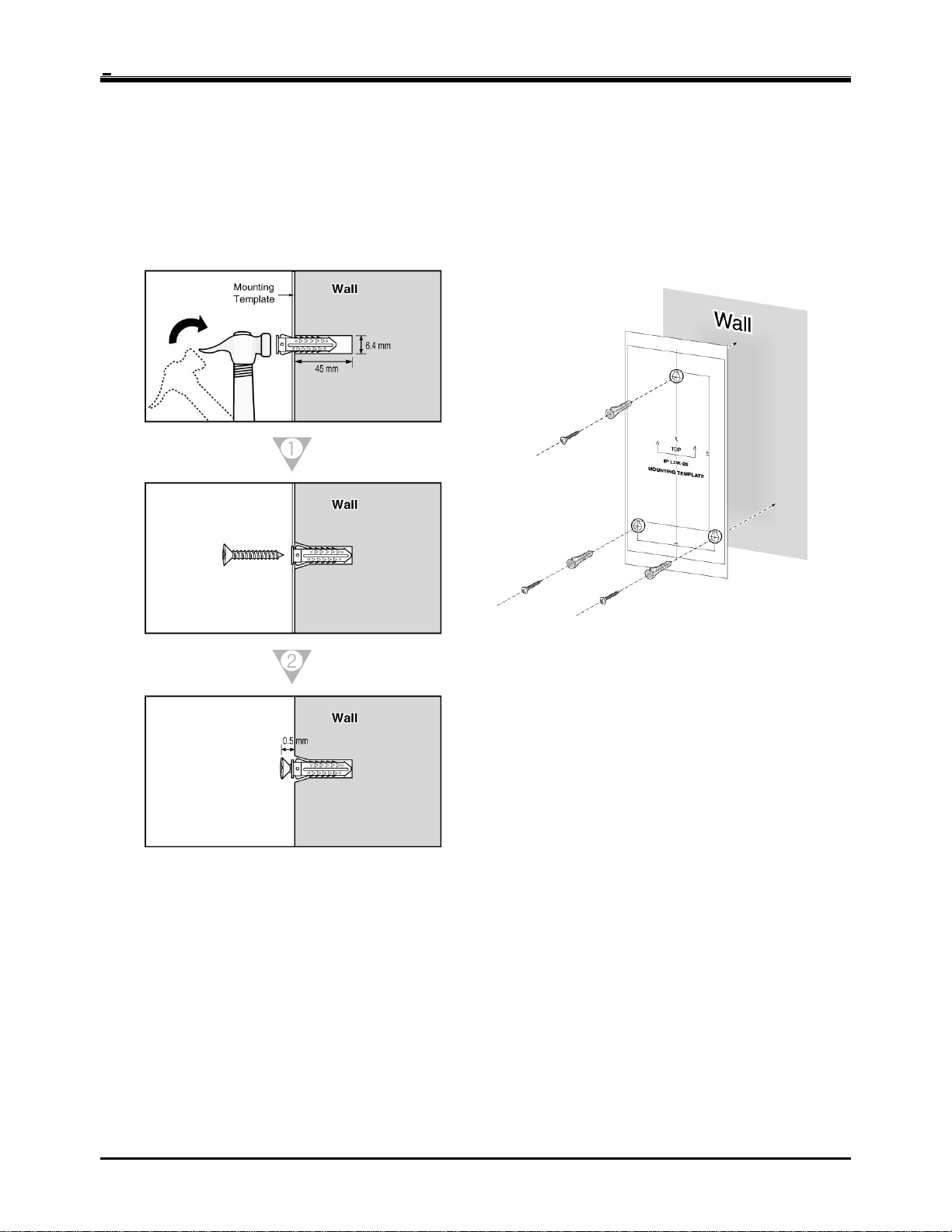
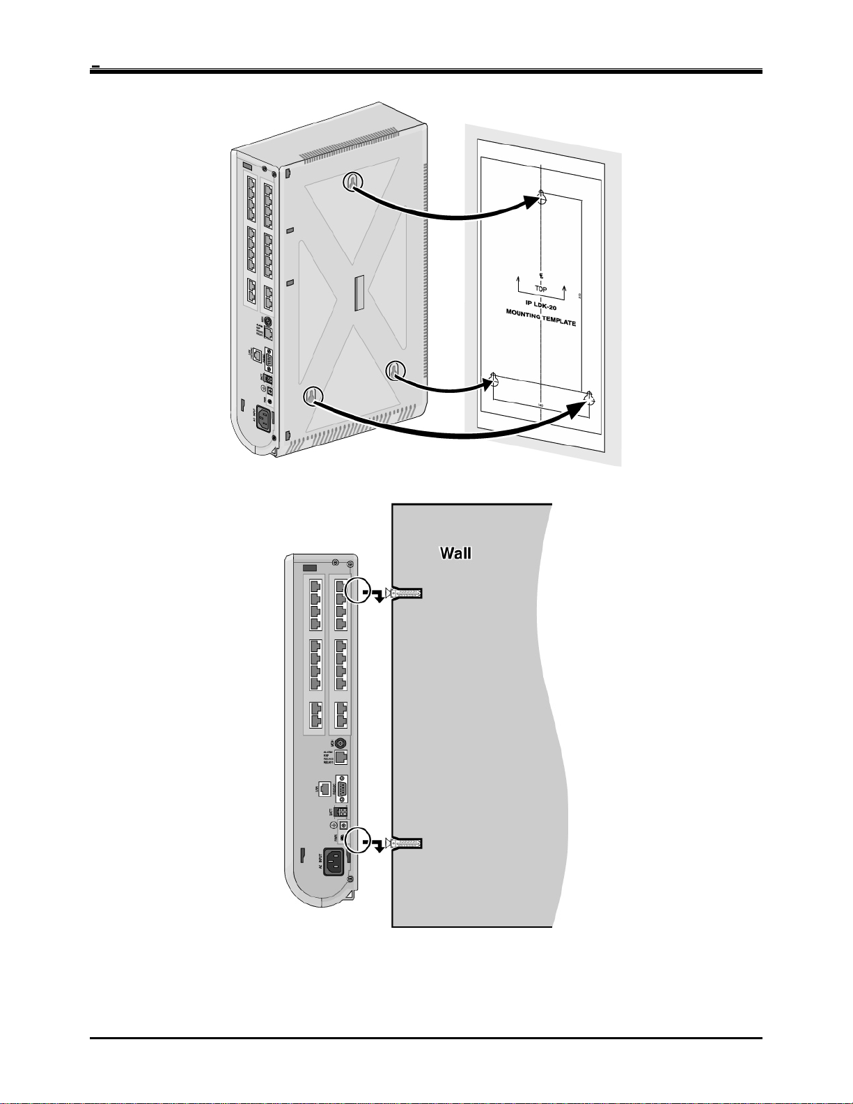
2.2.8 KSU mounting
2.2.8.1 Wall mounting
1. Install 3 anchor plugs in the wall using the mounting template included for accurate placement (Figure 2.2.8.1a).
2. Attach the mounting template with the included 3 screws.
3. Hook the KSU onto the screws, making sure that the system slides down securely (Figure 2.2.8.1b).
Figure 2.2.8.1a Mounting Template
17
IP LDK-20 Installation Manual KSU Installation
Figure 2.2.8.1b KSU Wall Mounting
※ Note : Be careful not to drop the KSU.
18
IP LDK-20 Installation Manual KSU Installation
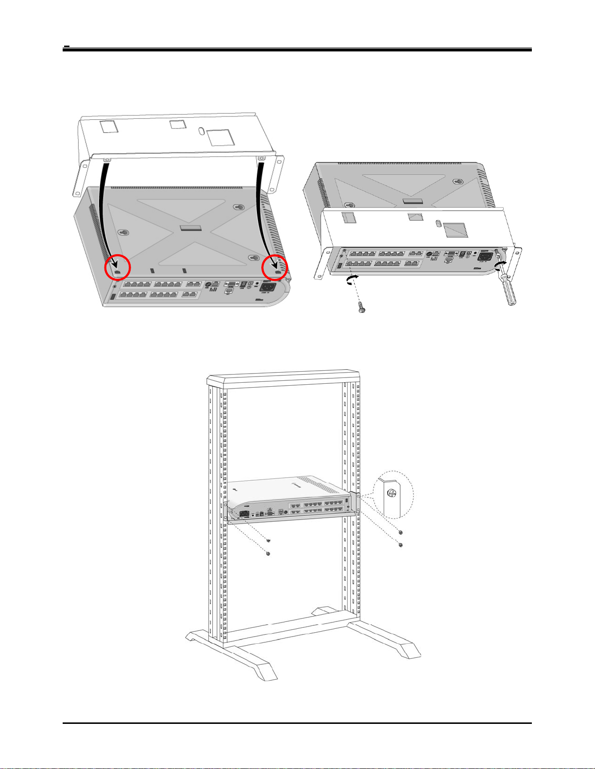
2.2.8.2 Rack mounting
1. Attach the rack bracket to the bottom of the IP LDK-20 system as shown in Figure 2.2.8.2a, and attach it to the
system securely by tightening the screws clockwise.
Figure 2.2.8.2a Rack Bracket
2. To attach the IP LDK-20 system to the rack, affix the bracket with the 4 screws provided (Figure 2.2.8.2b).
Figure 2.2.8.2b KSU Rack Mounting
19
IP LDK-20 Installation Manual Board Installation
SECTION 3. BOARD INSTALLATION
3.1 Installation of the Boards
Prior to Board Installation, the following should be considered:
CAUTION
• Power must be turned OFF.
• To protect the system from static electricity, do not touch the boards. To discharge static, touch a grounded
object, or wear a grounding strap.
• Insert boards carefully to avoid bending connector pins (male pins on MBUB).
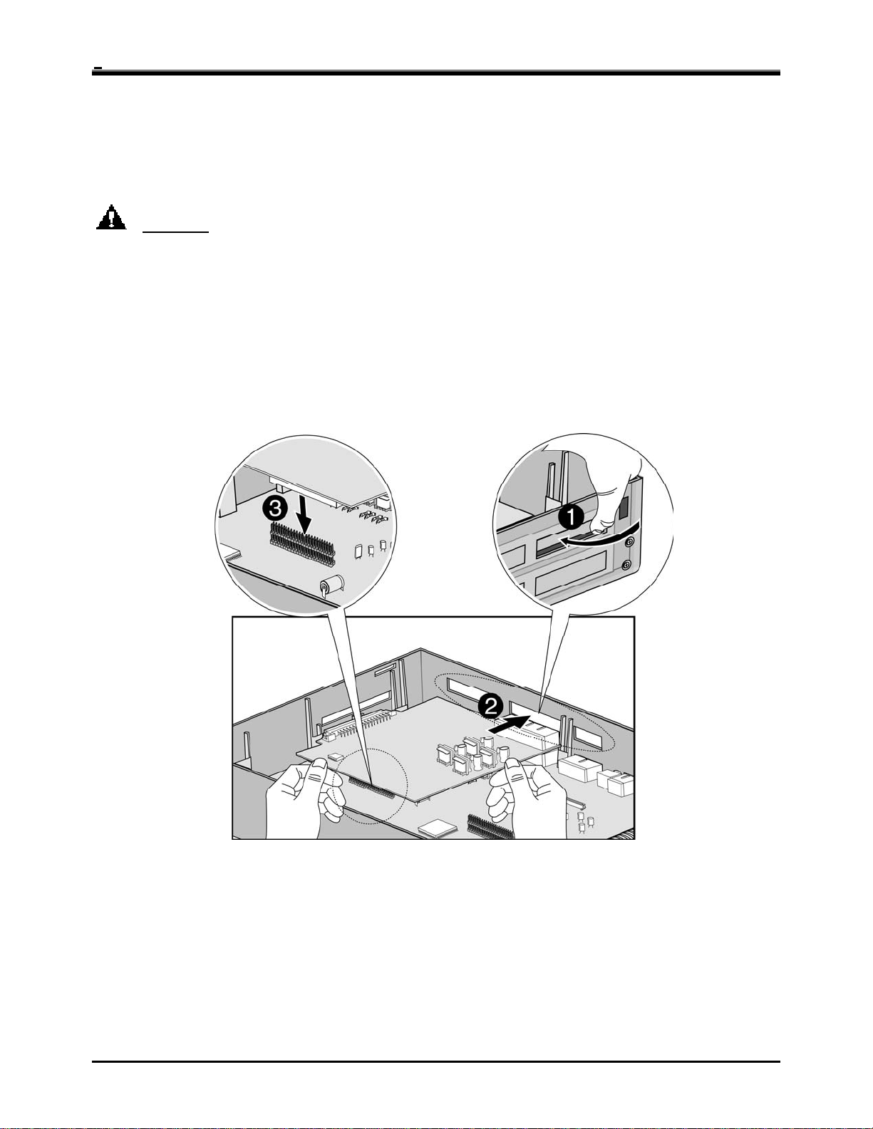
To install the board, perform the following Steps:
1. Before inserting the board, remove the dummy, shown #1 in Figure 3.1.
2. Holding the board as shown in #2 of the diagram, insert the board in the direction of the arrow carefully so that the
board securely engages with the connector on the main board (#3).
Figure 3.1 Board Installation
20
 Loading...