


REFRIGERATOR
SERVICE MANUAL
CAUTION
BEFORE SERVICING THE PRODUCT,
READ THE SAFETY PRECAUTIONS IN THIS MANUAL.
MODELS:
LBC20514TT

CONTENTS
Safety Precautions………………………………………………................................ 2
1- Specifications…………………………………………………................................ 3
2- Parts Identifications …………………………………………................................ 4
3- Disassembly……………………………………………………............................... 5 Door……………………………………………………………................................... 5 Door Switch……………………………………………………...................................5 Fan and Fan Motor……………………………………………..................................6 Defrost Control Assembly ……………………………………..................................6 Lamp……………………………………………………………..................................6 Refrigerator Control Box……………………………………….................................6 Multi Duct……………………………………………………….................................. 6
4- Ajustment……………………………………………………....................................7
Compressor…………………………………………………….................................. 7
PTC-Starter…………………………………………………….................................. 7
OLP (Overload Protector)…………………………………….................................. 8
To Remove the Cover PTC………………………………….................................. 8
5- Circuit Diagram……………………………………………..................................... 9
6- Troubleshooting……………………………………...................................……….10 Compressor and Electric Components…………………....................................…10 PTC and OLP …………………………………………....................................…….11
Other Electrical Components………………………….....................................……12
Service Diagnosis Chart……………………………....................................………13
Refrigeration Cycle…….………………………………....................................……14
7- Operation Principle and Repair Method of Ice Maker….................................16
8- Description of Function and Circuit of MICOM……….............................……19
11Refrigerator Exploded View …....................................................................... 38
SAFETY PRECAUTIONS
Pleasereadthefollowinginstructionsbeforeservicingyour |
|
|
refrigerator. |
|
|
1.Checktherefrigeratorforcurrentleakage. |
7.Beforetiltingtherefrigerator,removeallmaterialsfrom |
|
2.Topreventelectricshock,unplugbeforeservicing. |
onorintherefrigerator . |
|
|
||
3.Alwayschecklinevoltageandamperage. |
8.Whenservicingtheevaporato,rwearglovestoprevent |
|
injuriesfromthesharpevaporatorfins. |
||
4.Usestandardelectricalcomponents. |
||
9.Serviceontherefrigeratorshouldbeperformedbya |
||
5.Don'ttouchmetalproductsinthefreezerwithwet |
||
qualifiedtechnician.Sealedsystemrepairmustbe |
||
hands.Thismaycausefrostbite. |
||
performedbyaCFCcertifiedtechnician. |
||
6.Preventwaterfromspilingontoelectricelementsorthe |
||
|
||
machineparts. |
|
- 2 -
1. SPECIFICATIONS
Specification
Color
Capacity
Dimensions (in)
Refrigerant
Climate Class
Control Type
Rating
Case Material
Door Material
Reversible Door
Lamp (F)
Lamp ( R )
Basket (F)
Basket ( R )
Shelf (F)
Shelf ( R )
Cover, TV
Drawer
Vegetable
Tray Meat
Multi Flow
Models
LBC20514TT
Titanium
20cuft
29.8 (W) x 32.2 (D) x 67.9 (H)
R134A (4.2oz)
Temperate(N)
F-control
115/60
EMBO(Normal)
VCM
Yes
1(40W/Blue)
2(40W/Blue)
1(plastic) 2 (1/3) 2 (2/3) 1 full
1 Wire
4 fix
Humidity Control
Wire (lower)
Yes
Yes
Yes
- 3 -
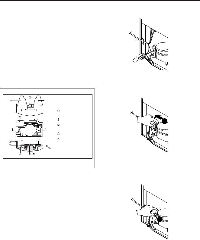
2. PARTS IDENTIFICATIONS
A |
|
B |
I |
|
|
C |
J |
|
|
D |
|
|
K |
E |
L |
|
|
F |
M |
G |
|
H |
|
|
N |
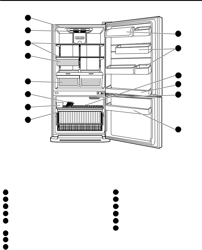
Use this section to become more familiar with the parts and features.
NOTE:This guide covers several different models.The refrigerator you have purchased may have some
or all of the items listed below.The locations of the features shown below may not match your model.
A |
Digital Sensor Control |
I |
Dairy Bin |
|
B |
Refrigerator Light |
J |
Design-A-Door |
|
C |
Shelves |
K |
Wire Freezer Shelf |
|
D |
Snack Pan |
L |
Refrigerator Door Rack |
|
E |
Optibin Crisper |
M Freezer Light |
||
|
Keeps fruits and vegetable fresh and crisp |
N Freezer Door Rack |
||
F |
Ice Tray* |
|||
*on some models |
||||
|
|
|||
GIce Bin
HWire Durabase
- 4 -
3. DISASSEMBLY
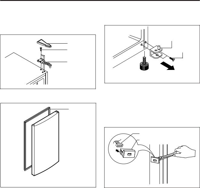
3-1 DOOR
Refrigerator Door
1.Remove the hinge cover by pulling it upwards.
2.Loosen the hexagonal bolts attaching the upper hinge to the body and lift the freezer door.
HINGE COVER
BOLT
HINGE
Figure 1
3.Pull out the door gasket to remove from the door foam assembly.
GASKET
Figure 2
Freezer Door
1.Loosen the hexagonal bolts attaching the lower hinge to the body to remove the refrigerator door only.
LOWER HINGE
BOLT
Figure 3
2.Pull out the door gasket to remove from the door foam assembly.
3-2 DOOR SWITCH
1.To remove the door switch, pry it out with a slotted-type driver, as shown in (Figure 4).
2.Disconnect the lead wire from the switch.
LEAD WIRE
DOOR SWITCH
Figure 4
- 5 -
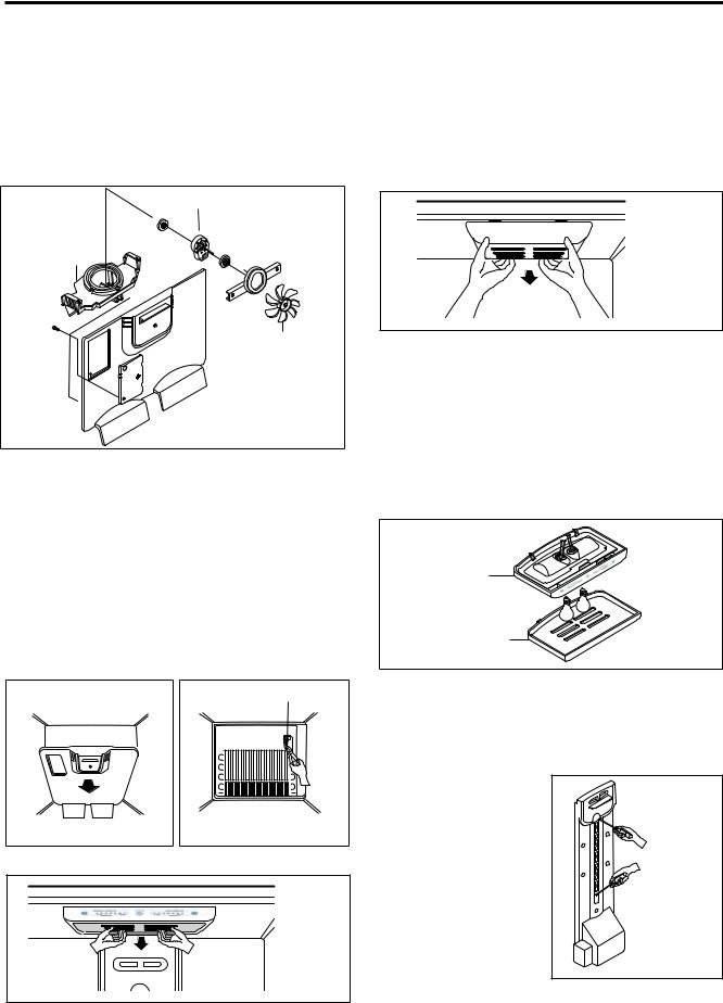
3-3 FAN AND FAN MOTOR
1.Remove the freezer shelf. (If your refrigerator has an icemaker, remove the icemaker first)
2.Remove the grille by pulling it out and by loosening a screw.
3.Remove the Fan Motor assembly by loosening 2 screws and disassemble the shroud.
4.Pull out the fan and separate the Fan Motor and Bracket.
5.Pull out the fan and separate the Fan Motor and Bracket.
FAN MOTOR
BRACKET
MOTOR
FAN
Figure 11
 GRILLE
3-4 DEFROST CONTROL ASSEMBLY
Defrost Control assembly consists of Defrost Sensor and FUSE–M.
The Defrost Sensor works to defrost automatically. It is attached to the metal side of the Evaporator and senses its Temperature.
Fuse-M is a safety device for preventing over-heating of the Heater when defrosting.
At 72°C, it turns the Defrost Heater off.
1.Pull out the grille assembly. (Figure 6)
2.Separate the connector with the Defrost Control assembly and replace the Defrost Control assembly after cutting the Tie Wrap. (Figure 7)
GRILLE ASSEMBLY |
DEFROST-CONTROL |
|||||||||||||||||||
|
|
|
|
|
|
ASSEMBLY |
||||||||||||||
|
|
|
|
|
|
|
|
|
|
|
|
|
|
|
|
|
|
|
|
|
|
|
|
|
|
|
|
|
|
|
|
|
|
|
|
|
|
|
|
|
|
|
|
|
|
|
|
|
|
|
|
|
|
|
|
|
|
|
|
|
|
|
|
|
|
|
|
|
|
|
|
|
|
|
|
|
|
|
|
|
|
|
|
|
|
|
|
|
|
|
|
|
|
|
|
|
|
|
|
|
|
|
|
|
|
|
|
|
|
|
|
|
|
|
|
|
|
|
|
|
|
|
|
|
|
|
|
|
|
|
|
|
|
|
|
|
|
|
|
|
|
|
|
|
|
|
|
|
|
|
|
|
|
|
|
|
|
|
|
|
|
|
|
|
|
|
|
|
|
|
|
|
|
|
|
|
|
|
|
|
|
|
|
|
|
|
|
|
|
|
|
|
|
|
|
|
|
|
|
|
|
|
|
|
|
|
|
|
|
Figure 6 |
Figure 7 |
3-5 LAMP
Figure 8
3-5-1 Refrigerator Compartment Lamp
1.Unplug the power cord from the outlet.
2.Remove refrigerator shelves.
3.Release the hooks on both ends of the lamp shield and pull the shield downward to remove it.
4.Turn the lamp counterclockwise.
5.Assemble in reverse order of disassembly. Replacement bulb must be the same specification as the original (Max. 60 W-2EA).
Figure 9
3-5-2 Freezer Compartment Lamp
1.Unplug refrigerator or disconnect power.
2.Reach behind light shield to remove bulb.
3.Replace bulb with a 60-watt appliance bulb.
4.Plug in refrigerator or reconnect power.
3-6 CONTROL BOX-REFRIGERATOR
1.First, remove all shelves in the refrigerator, than remove the Refrigerator control Box by loosening 2 screws.
CONTROL BOX
COVER LAMP
Figure 10
2.Remove the Refrigerator Control Box by pulling it downward.
3.Disconnect the lead wire on the right position and separate the lamp sockets.
3-7 MULTI DUCT
1. Remove an upper and lower Cap by using a flat screwdriver, and loosen 3 screws. (Figure 11)
2. Disconnect the lead wire on the bottom position.
Figure 11
- 6 -

4. ADJUSTMENT
4-1 COMPRESSOR
4-1-1 Role
The compressor intakes low temperature and low pressure gas from the evaporator of the refrigerator and compresses this gas to high-temperature and high-pressure gas. It then delivers the gas to the condenser.
4-1-2 Composition
The compressor includes overload protection. The PTC starter and OLP (overload protector) are attached to the outside of the compressor. Since the compressor is manufactured to tolerances of 1 micron and is hermetically sealed in a dust and moisture-free environment, use extreme caution when repairing it.
4-1-3 Note for Usage
(1)Be careful not to allow over-voltage and over-current.
(2)If compressor is dropped or handled carelessly, poor operation and noise may result.
(3)Use proper electric components appropriate to the Particular Compressor in your product.
(4)Keep Compressor dry.
If the Compressor gets wet (in the rain or a damp environment) and rust forms in the pin of the Hermetic Terminal, poor operation and contact may result.
(5)When replacing the Compressor, be careful that dust, humidity, and soldering flux don’t contaminate the inside of the compressor. Dust, humidity, and solder flux contaminate the cylinder and may cause noise, improper operation or even cause it to lock up.
4-2 PTC-STARTER
4-2-1 Composition of PTC-Starter
(1)PTC (Positive Temperature Coefficient) is a no-contact semiconductor starting device which uses ceramic material consisting of BaTiO3.
(2)The higher the temperature is, the higher the resistance value. These features are used as a starting device for the Motor.
4-2-2 Role of PTC-Starter
(1)The PTC is attached to the Sealed Compressor and is used for starting the Motor.
(2)The compressor is a single-phase induction motor. Durign the starting operation, the PTC allows current flow to both the start winding and main winding.
4-2-3 PTC-Applied Circuit Diagram
Starting Method for the Motor
OVERLOAD PROTECTOR |
|
|
|
|
N |
|
C |
|
|
|
|
|
||
PTC |
5 |
COMPRESSOR |
||
2 |
MOTOR |
|
||
|
|
|
||
|
S |
M |
M |
|
|
S |
|||
3 |
6 |
|||
|
|
|||
L1 |
|
|
|
|
PTC STARTER |
SEALED |
|
||
TERMINAL |
||||
Resistance Starter Capacitor Running |
||||
|
|
|||
Figure 12
4-2-4 Motor Restarting and PTC Cooling
(1)It requires approximately 5 minutes for the pressure to equalize before the compressor can restart.
(2)The PTC device generates heat during operation. Therefore, it must be allowed to cool before the compressor can restart.
4-2-5 Relation of PTC-Starter and OLP
(1)If the compressor attempts to restart before the PTC device is cooled, the PTC device will allow current to flow only to the main winding.
(2)The OLP will open because of the over current condition. This same process will continue (3 to 5 times) when the compressor attempts to restart until the PTC device has cooled. The correct OLP must be properly attached to prevent damage to the compressor.
Parts may appear physically identical but could have different electrical ratings. Replace parts by part number and model number. Using an incorrect part could result in damage to the product, fire, injury, or possibly death.
4-2-6 Note for Using the PTC-Starter
(1)Be careful not to allow over-voltage and over-current.
(2)Do not drop or handle carelessly.
(3)Keep away from any liquid.
If liquid such as oil or water enters the PTC,
PTC materials may fail due to breakdown of their insulating capabilities.
(4)If the exterior of the PTC is damaged, the resistance value may be altered. This can cause damage to the compressor and result in a no-start or hard-to-start condition.
(5)Always use the PTC designed for the compressor and make sure it is properly attached to the compressor. Parts may appear physically identical but could have different electrical ratings. Replace parts by part number and model number. Using an incorrect part could result in damage to the product, fire, injury, or possibly death.
- 7 -
4-3 OLP (OVERLOAD PROTECTOR)
4-3-1 Definition of OLP
(1)OLP (OVERLOAD PROTECTOR) is attached to the Compressor and protects the Motor by opening the circuit to the Motor if the temperature rises and activating the bimetal spring in the OLP.
(2)When high current flows to the Compressor motor, the Bimetal works by heating the heater inside the OLP, and the OLP protects the Motor by cutting off the current flowing to the Compressor Motor.
4-3-2 Role of the OLP
(1)The OLP is attached to the Sealed Compressor used for the Refrigerator. It prevents the Motor Coil from being started in the Compressor.
(2)For normal operation of the OLP, do not turn the Adjust Screw of the OLP in any way.
(OVERLOAD PROTECTOR cross section)
Part
|
|
Customer part |
|
12345678 |
number |
|
Lot code/ |
|
|
|
|
330 FBYY |
-S1 BOX98 |
date code |
|
||
Electrical |
|
Physical |
characteristics |
|
termination |
part number |
|
part number |
No. Name
 Base, phenolic (UL 94 V-0 rated)
 Movable arm support, plated steel
Stationary contact support, plated steel
 Heater support, plated steel
Heater, resistance alloy
 Disc, thermostatic alloy
Movable arm, spring temper copper alloy
 Contact, movable, silver on copper
Contact, stationary, silver on copper
 Slug, plated steel
Cover, polyester (UL 94 V-0 rated)
 Pin connector, plated copper alloy (To engage 2.33/2.66 mm dia. pin)
  Quick-connect terminal, brass, conforms to UL 310, MEMA
DC-2, DIN 46344
Figure 13
4-4 TO REMOVE THE COVER PTC
1) Remove the Cover Back M/C.
(2) Remove the screw on Cover PTC.
1
(3)Remove two Housings on upper part of Cover PTC.
(4)Take out the cover PTC from upper to lower position like ( 1 ).
 2
2
(5)Turn 45¡ in the direction of (2)and take it out.
(6)Assembly in reverse order of disassembly.
- 8 -

5. CIRCUIT DIAGRAM
|
|
|
|
|
|
|
|
|
|
|
|
|
|
PWB(PCB) ASSEMBLY,DISPLAY |
|
|
|
|
|
|
|
|
|
|
||||||||||||||||||||||||||
|
|
|
|
|
|
|
|
|
|
|
|
|
|
|
|
|
|
|
|
|
|
|
|
|
|
|
|
|
|
|
|
|
|
|
|
|
|
|
|
|
|
|
|
|
|
|
|
|
|
|
|
|
|
|
|
|
|
|
|
|
|
|
|
CON101 |
1 |
2 |
3 |
4 |
5 |
6 |
7 |
8 |
|
|
9 |
|
|
|
|
|
|
|
|
|
|
|
|
|
|
|
|||||||||||
|
|
|
|
|
|
|
|
|
|
|
|
|
WH |
BO |
BL |
SB |
PR |
BK |
PK |
WH |
YL |
|
|
|
|
|
|
|
|
|
|
|
|
|
S/W |
|||||||||||||||
|
|
|
|
|
|
|
|
|
|
|
|
|
|
|
|
|
/RD |
/WH |
|
|
|
|
|
|
|
|
|
|
|
|
|
|||||||||||||||||||
|
|
|
|
|
|
|
|
|
|
|
|
|
|
|
|
|
|
|
|
|
|
|
|
|
|
|
|
|
|
|
|
|||||||||||||||||||
|
|
|
|
|
|
|
|
|
|
|
|
|
|
|
|
|
|
|
|
|
|
|
|
|
|
|
|
|
|
|
|
|
|
|
|
|
|
|
|
|
|
|
|
|
|
|
DOOR-R |
PERCEPTION |
||
|
|
F-FAN |
|
|
STEPPING |
|
|
|
|
|
|
|
|
|
|
|
|
|
|
|
|
|
|
|
|
|
|
|
|
|
|
|
|
|
|
|
|
|||||||||||||
|
|
|
|
|
|
|
|
|
|
|
|
|
|
|
|
|
|
|
|
|
|
|
|
|
|
|
|
|
|
|
|
|
|
|
|
|||||||||||||||
|
|
|
|
|
|
|
|
|
|
|
|
|
|
|
|
|
|
|
|
|
|
|
|
|
|
|
|
|
|
|
|
|
||||||||||||||||||
|
|
|
|
|
|
|
|
|
|
|
|
|
|
|
|
|
|
|
|
|
|
|
|
|
|
|
|
|
|
|
|
|
|
|
||||||||||||||||
|
|
|
|
|
|
|
|
|
|
|
|
|
|
|
|
|
|
|
|
|
|
|
|
|
|
|
|
|
|
|
|
|
|
|
|
|
|
|
|
|||||||||||
|
|
|
|
|
|
|
|
MOTOR |
|
|
|
|
|
|
|
|
|
|
|
|
|
|
|
|
|
|
|
|
|
|
|
|
|
|
|
|
|
|
|
|
|
|
|
|
|
|
||||
|
|
|
|
|
|
|
|
|
|
|
|
|
|
|
|
|
|
|
|
|
|
|
|
|
|
|
|
|
|
|
|
|
|
|
|
|
|
|
|
|
|
|
|
|
|
|
C |
D |
||
|
|
|
|
|
|
|
|
|
|
|
|
|
|
|
|
|
|
|
|
|
|
|
|
|
|
|
|
|
|
|
|
|
|
|
|
|
|
|
|
|
|
|
|
|
|
|
|
|
|
|
|
|
|
|
|
|
|
|
|
|
|
|
|
|
|
|
|
|
|
|
|
|
|
|
|
|
|
|
|
|
|
|
|
|
|
|
|
|
|
|
|
|
|
|
|
|
|
|
|
|
|
PR |
GY |
WH |
BL |
BK |
YL |
RD |
|
|
/RDWH |
BO |
/WHBL |
SB |
|
|
|
|
|
|
|
|
|
|
PR |
BK |
PK |
WH |
|
|
YL |
GY |
GY |
|||||||||||||||||||
1 |
|
2 |
3 |
4 |
|
5 |
6 |
7 |
8 |
9 |
10 |
11 |
12 |
13 |
|
|
|
1 |
|
2 |
|
3 |
|
4 |
5 |
6 |
7 |
8 |
9 |
10 |
11 |
12 |
||||||||||||||||||
CON4 |
|
|
|
|
|
|
|
|
|
|
|
|
|
|
|
|
|
|
|
|
|
|
CON5 |
|
|
|
|
|
|
|
|
|
|
|
|
|
|
|
|
|
|
|
|
|||||||
PWB(PCB) ASSEMBLY, MAIN
L1
|
|
|
|
|
11 10 |
9 |
8 |
7 |
6 |
5 |
4 |
3 |
2 |
1 |
|
|
7 |
6 |
5 |
4 |
3 |
2 |
1 |
|
POWER |
|
|
|
|
SB |
|
BN |
|
YL |
|
BL |
|
BL |
|
BK |
|
|
BN |
|
RD |
|
|
|
SB |
SUPPLY |
|
|
|
|
CON1 |
|
|
|
|
|
|
|
|
|
|
|
|
CON2 |
|
|
|
|
|
|
CORD |
|
|
|
|
SB |
BN |
YL |
BL |
BL |
BK |
|
|
BN |
RD |
|
|
SB |
|||||||
|
|
|
|
|
|
|
|
|
||||||||||||||||
N |
|
|
|
|
|
|
|
|
|
|
|
|
|
|
|
|
|
|
|
|
|
|
|
|
L |
|
|
|
|
|
|
|
|
|
|
|
|
|
|
|
|
|
|
|
|
|
|
|
|
|
|
GN/YL |
|
|
|
|
|
|
|
|
|
|
|
|
|
|
|
|
|
|
|
|
|
|
|
|
(GN) |
|
|
|
|
|
|
|
|
|
|
|
|
|
|
|
|
|
|
|
|
|
|
|
|
|
|
|
|
|
|
|
|
|
|
|
|
|
|
|
|
|
|
BK |
BK |
|||
|
|
ICE MAKER PART |
|
|
|
|
|
|
|
|
|
|
|
|
|
|
|
|
|
|
||||
GN/YL |
|
|
|
|
|
|
|
|
|
FUSE-M |
(98C) |
|
|
|
|
|
|
|
|
|
|
|
|
|
(GN) |
|
|
|
|
|
|
|
|
|
|
|
|
|
|
|
|
|
|
|
|
|
|
||
|
|
|
|
|
|
|
|
|
|
|
|
|
|
|
|
|
|
|
|
|
|
|
|
|
|
SENSORICE |
|
|
HEATER, SHEATH |
M |
MAKERICE MOTOR |
|
BK POWER |
S/W |
|
|
I/MAKER |
W/VALVE |
CAPACITOR PART |
|
OLP |
|
|
|
-CFAN |
||||
|
|
|
|
|
|
Cs |
4 |
5 |
S |
|
|
|
||||||||||||
|
|
|
|
|
|
|
|
|
|
|
|
|
|
|
|
Cr |
|
PK |
|
|
|
|
|
|
|
|
|
|
|
|
|
|
|
|
|
|
|
V |
|
|
|
|
|
|
|
|
|
|
M |
|
|
|
|
|
|
|
|
|
|
|
|
|
|
|
RD |
|
2 |
|
|
|
|
|
|
|
|
|
|
|
|
|
|
|
|
|
|
|
|
|
|
|
|
|
|
|
|
|
|
||
CON5 2WH |
WH1 |
CON4 WH1 |
WH1 |
CON3 |
CON2 BK2 |
WH1 |
CON1 |
BL2 |
1BK |
CON6 |
1RD |
|
|
|
|
BL |
PTC STARTER |
M |
|
|
GN |
|
|
|
|
|
|
|
|
|
|
/YL |
|
BL |
|||||||||||||||
|
|
|
|
|
|
|
|
|
|
|
|
|
|
|
|
|
3 |
6 |
|
|
|
(GN) |
|
|
|
|
|
|
|
|
|
|
|
|
|
|
|
|
|
|
|
|
|
|
COMP' EARTH |
|
|||
|
|
|
|
|
|
|
|
|
|
|
|
|
|
|
|
|
|
|
|
|
PART |
|
|
|
PWB (PCB) ASSEMBLY, ICE MAKER |
|
|
|
|
|
|
COMP' ACCESSORIES |
|
|
|
|
|
|
|||||||||||
|
* ALTERNATIVE COMP' ACCESSORIES |
|||
|
Cr |
BK |
|
|
*PLUG TYPE, ICE MAKER PART, CAPACITOR PART, |
BL |
OLP |
L |
|
N |
||||
P.T.C START OPTION, COMP' EARTH PART AND COMP' |
|
|||
ACCESSORIES ON CIRCUIT DIAGRAM ARE SUBJECT |
|
|
|
|
TO CHANGE IN DIFFERENT LOCALITIES AND MODEL TYPE. |
|
|
|
|
|
PTC |
|
|
|
|
COMBO KIT(PTC+OLP) |
|
|
|
CON6 1 |
PK |
A |
F-DOOR |
|
2 |
PK |
B |
PERCEPTION S/W |
|
3 |
BO |
DEF-SENSOR |
||
4 |
BO |
|||
|
|
|||
5 |
WH |
R-SENSOR |
||
6 |
WH |
|||
|
|
|||
7 |
BL |
F-SENSOR |
||
8 |
BL |
|||
|
|
|||
|
S/W-F |
com |
com |
S/W-R |
com |
com |
FUSE-M (72 C) |
DOOR |
nc |
nc |
DOOR |
nc |
nc |
|
HEATER,SHEATH |
A B |
LAMP-F |
|
C D |
LAMPS-R |
RD |
BO |
|
PR |
|||
|
|
|
|
|||
BL |
|
BL |
|
|
BL |
|
|
|
* P.T.C START OPTION |
|
|||
|
MC,MQ COMP' |
EG COMP' |
|
|||
|
2 |
|
3 |
4 |
5 |
4 |
6 |
3 |
6 |
2 |
5 |
MEZ48108403
BK:BLACK |
WH:WHITE |
BN:BROWN |
BO:BRIGHT ORANGE |
SB:SKY BLUE |
RD:RED |
YL:YELLOW |
PK:PINK |
GN:GREEN |
PR:PURPLE |
GY:GREY |
BL:BLUE |
- 9 -
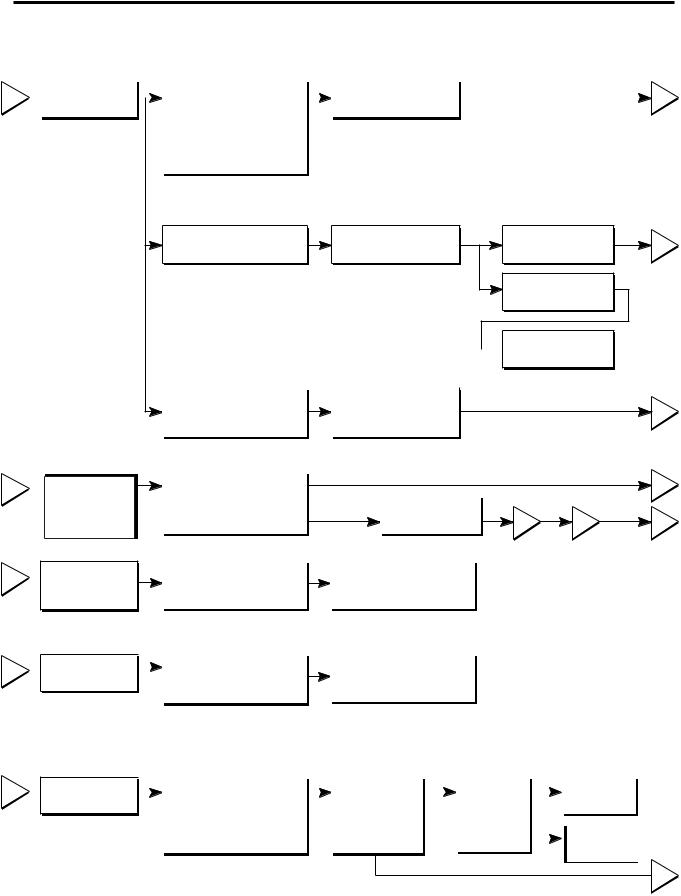
6. TROUBLESHOOTING
6-1 COMPRESSOR AND ELECTRIC COMPONENTS
1
2
3
4
|
|
|
Remove PTC-Starter |
|
(Rated voltage |
YES |
|
Power Source. |
|
|
from compressor and |
|
±10%)? |
|
2 |
|
|
|
|
|
|
||
|
|
|
measure voltage |
|
|
|
|
|
|
|
|
|
|
||
|
|
|
between Terminal C of |
|
|
|
|
|
|
|
compressor and |
|
|
|
|
|
|
|
terminal 5 or 6 of PTC. |
|
|
|
|
|
YES |
|
5 |
No voltage. |
OLP disconnected? |
Replace OLP. |
|
|
NO |
Check connection |
|
|
|
condition. |
|
 Reconnect.
|
Applied voltage isn't |
|
Advise customer that |
|
5 |
|
in acceptable range. |
|
power supply needs to be |
||
|
(115V ±10%) |
|
checked by an electrician. |
|
|
|
|
|
|
|
|
Check
Check resistance
resistance of of motor
motorpressorc.
compressor.
.
Check resistance of PTC-Starter.
Check OLP.
|
|
|
|
|
|
The range of resistance is between 1~50 |
? (ok) |
|||
|
Check the resistance |
|
|
|
|
|
|
|
3 |
|
|
between M-C, S-C and |
Open or short |
Replace |
|
|
|
||||
|
M-S in motor compressor. |
|
|
|
|
|||||
|
|
|
|
|
compressor |
3 |
4 |
5 |
||
|
|
|
|
|
|
|
|
|||
|
|
|
|
|
|
|
|
|
|
|
|
Check resistance of |
|
Refer |
|
to Page 12. |
|
|
|
|
|
|
two terminals in |
|
|
|
|
|
|
|
||
|
PTC-Starter. |
|
|
|
|
|
|
|
|
|
|
|
|
|
|
|
|
|
|
|
|
|
|
|
|
|
|
|
|
|
|
Check resistance of two |
|
|
Refer |
to Page 12. |
|
|
|
terminals in OLP. |
|
|
|||
|
|
|
|
|
|
||
|
|
|
|
|
|
|
|
|
|
|
|
|
|
|
|
Check
5
starting state.
|
|
Check the power supply |
|
Supply |
YES |
Did |
YES |
|
Compressor |
|
|
|
|
|
under load. |
|
voltage rating |
|
compressor |
|
|
is OK |
|
||
|
|
(Compressor attempting |
|
with ±10%. |
|
start? |
|
|
|
|
|
|
|
|
|
|
|
|
|
|
|
|
|
||
|
|
to re-start after being off |
|
|
|
|
|
|
|
Replace the |
|
|
|
|
for 5 minutes). |
|
|
|
|
|
|
|
|
|
|
|
|
|
|
|
NO |
|
compressor |
|
||||
|
|
|
|
|
|
|
|
|
|
|||
|
|
|
|
|
|
|
|
|||||
|
|
|
|
|
|
|
|
|
|
|
|
|
 1
1
NO
- 10 -
6-2 PTC AND OLP
Normal operation of compressor is impossible or poor.
|
|
Separate PTC-Starter |
|
Observation value is |
|
|
|
|
from Compressor and |
|
115V/60Hz : 6.8 ? ±30% |
|
|
|
|
measure resistance |
|
|
|
|
|
|
|
|
|
|
|
|
|
between No. 5 and 6 |
|
|
|
|
|
|
|
|
|
||
|
|
of PTC-Starter with a |
|
|
|
|
|
|
Tester. |
|
|
|
|
|
|
(Figure 19) |
|
|
|
|
|
|
|
|
The resistance value |
|
|
|
|
|
|
is 0 ? (short) or |
|
|
|
|
|
|
8(open). |
|
|
|
|
|
|
|
|
|
Replace PTC-
Starter.
|
Separate OLP from |
Shows continuity |
|
Check another |
|
|
compressor and check |
|
|
electric component. |
|
|
resistance value between |
|
|
||
|
|
|
|
||
|
two terminals of OLP whit a |
|
|
|
|
|
tester. |
Open |
|
|
|
|
(Figure 20) |
|
|
|
Replace OLP. |
|
|
|
|||
|
|
|
|
|
|
6 |
5 |

 ?
?
Figure 19 |
Figure 20 |
- 11 -
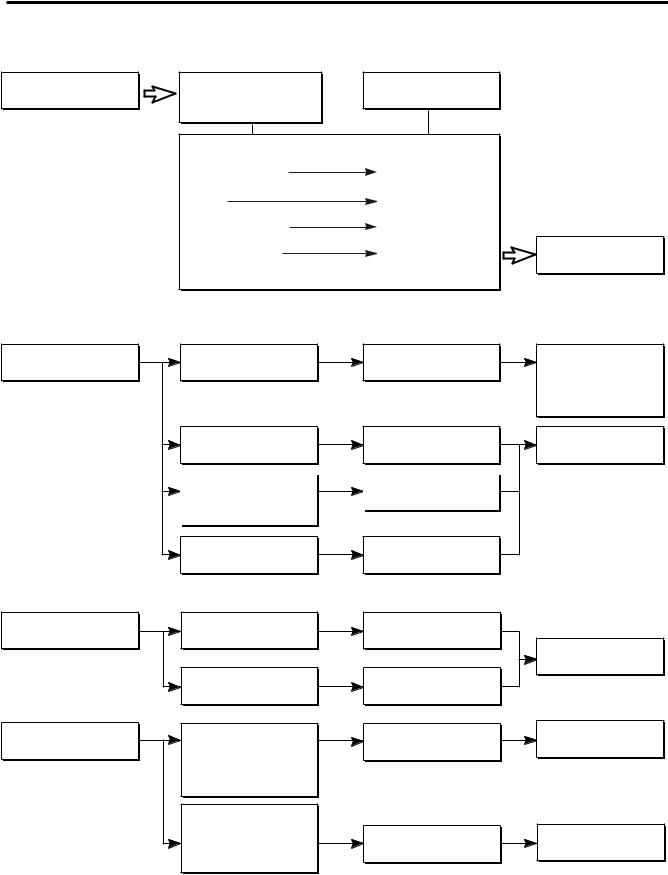
6-3 OTHER ELECTRICAL COMPONENTS
Not cooling at all
Compressor doesn't run.
Check for open short or
Cause
incorrect resistance readings in the following components
|
a. Starting devices |
Short, open, or broken. |
|
|
b. OLP |
Poor contact |
|
|
or shorted. |
|
|
|
|
|
|
|
c. Compressor coil |
Coil open or shorted. |
|
|
d.Wiring harness |
Poor contact |
Replace |
|
|
or shorted. |
indicated component. |
Poor cooling performance |
|
|
|
Compressor runs |
Check starting |
Low voltage. |
Advise customer that |
poorly. |
voltage. |
|
the power supply |
|
|
|
needs to be checked |
|
|
|
by an electrician. |
Check voltage at |
Poor or broken or |
Replace |
starting devices. |
open contact. |
indicated component. |
|
Check current flowing |
|
Shorted. |
|
|
in sub-coil of |
|
|
|
|
Compressor. |
|
|
|
Check rating of OLP. |
Lack of capacity. |
Fan motor |
Check wiring circuit. |
Wire is open or |
|
doesn't run. |
shorted. |
||
|
|||
|
|
Replace |
|
|
|
indicated component. |
|
|
Check Fan Motor. |
Coil is shorted |
|
|
or open. |
||
|
|
Heavy frost buildup on evaporator
Check current flow in |
Open. |
Replace |
the following |
indicated component. |
|
components: |
|
|
Sensor |
|
|
Fuse-M |
|
|
Check current flow in |
Open. |
Replace |
the defrost heater. |
defrost heater. |
|
|
|
- 12 -

6-4 SERVICE DIAGNOSIS CHART
COMPLAINT |
POINTS TO BE CHECKED |
REMEDY |
|
|
|
No Cooling. |
•Is the power cord unplugged from the outlet? |
•Plug into the outlet. |
|
•Check if the power switch is set to OFF. |
•Set the switch to ON. |
|
•Check if the fuse of the power switch is shorted. |
•Replace the fuse. |
|
•Measure the voltage of the power outlet. |
•If the voltage is low, correct the wiring. |
|
|
|
Cools poorly. |
•Check if the unit is placed too close to the wall. |
•Place the unit about 4 inches (10 cm) from the wall. |
|
•Check if the unit is placed too close to the stove, |
•Place the unit away from these heat sources. |
|
gas cooker, or in direct sunlight. |
|
|
•Is the ambient temperature too high or |
•Lower the ambient temperature. |
|
the room door closed? |
|
|
•Check if food put in the refrigerator is hot. |
•Put in foods after they have cooled down. |
|
•Did you open the door of the unit too often |
•Don't open the door too often and close |
|
or check if the door is sealed properly? |
it firmly. |
|
•Check if the Control is set to Warm position. |
•Set the control to Recommended position. |
|
|
|
Foods in the |
•Is food placed in the cooling air outlet? |
•Place foods in the high-temperature section. |
Refrigerator |
|
(front part) |
are frozen. |
•Check if the control is set to colder position. |
•Set the control to Recommended position. |
|
•Is the ambient temperature below 41°F(5° C)? |
•Set the control to Warm position. |
|
|
|
Condensartion or ice |
•Is liquid food sealed? |
•Seal liquid foods with wrap. |
forms inside |
•Check if food put in the refrigerator is hot. |
•Put in foods after they have cooled down. |
the unit. |
•Did you open the door of the unit too |
•Don't open the door too often and close |
|
often or check if the door is sealed properly? |
it firmly. |
|
|
|
Condensartion forms |
•Check if the ambient temperature and humidity |
•Wipe moisture with a dry cloth. It will disappear |
in the Exterior Case. |
of the surrounding air are high. |
in low temperature and humidity. |
|
•Is there a gap in the door gasket? |
•Fill up the gap. |
|
|
|
There is abnormal |
•Is the unit positioned in a firm and even place? |
•Adjust the Leveling Screw, and position the |
noise. |
|
refrigerator in a firm place. |
|
•Are any unnecessary objects placed |
•Remove the objects. |
|
in the back side of the unit? |
|
|
•Check if the Tray Drip is not firmly fixed. |
•Fix the Tray Drip firmly in the original position. |
|
•Check if the cover of the compressor enclosure |
•Place the cover in its original position. |
|
in the front lower side is taken out. |
|
|
|
|
Door does not |
•Check if the door gasket is dirty with |
•Clean the door gasket. |
close well. |
an item like juice. |
|
|
•Is the refrigerator level? |
•Position in the firm place and level the |
|
|
Leveling Screw. |
|
•Is there too much food in the refrigerator? |
•Make sure food stored in shelves does not prevent |
|
|
the door from closing. |
|
|
|
Ice and foods |
•Check if the inside of the unit is dirty. |
•Clean the inside of the unit. |
smell unpleasant. |
•Are foods with a strong odor unwrapped? |
•Wrap foods that have a strong odor. |
|
•The unit smells of plastic. |
•New products smell of plastic, but this |
|
|
will go away after 1-2 weeks. |
|
|
|
Other possible problems:
Check if frost forms in the freezer.
Check the refrigeration system.
Check the
Thermistor.
Not
defrosting
The system
is faulty.
The operation of  the Thermistor is
incorrect.
Check Components of the defrosting circuit.
Perform sealed system repair.
Replace the
Thermistor.
- 13 -
 Loading...