


|
|
Internal Use Only |
|
|
|
North/Latin America |
http://aic.lgservice.com |
|
Europe/Africa |
http://eic.lgservice.com |
|
Asia/Oceania |
http://biz.lgservice.com |
|
PLASMA TV
MANUAL DE SERVICIO
CHASIS : PP91A
MODELO : 42PQ30R 42PQ30R-MA
ATENCIÓN
Antes de dar servicio al chasis, lea las PRECAUCIONES DE SEGURIDAD en este manual.
CONTENIDO
CONTENIDO ............................................................................................................................ |
2 |
PRECAUCIONES DE SEGURIDAD ......................................................................................... |
3 |
ESPECIFICACIONES ................................................................................................................ |
4 |
INSTRUCCIONES DE AJUSTE ............................................................................................... |
8 |
DIAGRAMA EN BLOQUE ...................................................................................................... |
16 |
VISTA EN DESPIECE ............................................................................................................. |
17 |
DIAGRAMA ESQUEMÁTICO...................................................................................................... |
|
TABLERO DE CIRCUITO IMPRESO .......................................................................................... |
|
Copyright©2009 LG Electronics. Inc. All right reserved. |
- 2 - |
LGE Internal Use Only |
Only for training and service purposes |
|
|
PRECAUCIONES DE SEGURIDAD
ADVERTENCIA: Antes de dar servicio a este chasis, lea "PRECAUCIONES RESPECTO A RADIACION POR RAYOS X", "INSTRUCCIONES DE SEGURIDAD" y "AVISO SOBRE SEGURIDAD DE PRODUCTOS"
INSTRUCCIONES DE SEGURIDAD
1.Cuando el receptor está en operación, se producen voltajes potencialmente tan altos como 25,000-29,000 voltios. Operar el receptor fuera de su gabinete o con la tapa trasera removida puede causar peligro de choque eléctrico.
(1)Nadie debe intentar dar servicio si no está debidamente familiarizado con las precauciones que son necesarias cuando se trabaja con un equipo de alto voltaje.
(2)Siempre descargue el ánodo del tubo de la imagen a tierra para evitar el riesgo de choque eléctrico antes de remover la tapa del ánodo.
(3)Descargue completamente el alto potencial del tubo de imagen antes de manipularlo. El tubo de la imagen es de alto vacío y, si se rompe, los fragmentos de vidrio salen despedidos violentamente.
2.Si se quemara algún fusible de este receptor de televisión, reemplácelo con otro especificado en la lista de partes.
3.Cuando reemplace tableros o plaquetas de circuitos, cuidadosamente enrolle sus alambres alrededor de las terminales antes de soldar.
4.Cuando reemplace un resistencia de vataje (resistor de película de óxido metálico) en el Tablero o Plaqueta de circuitos, mantenga la resistencia a un mínimo de 10mm de distancia.
5.Mantenga los alambres lejos de componentes de alto voltaje o de alta temperatura.
6.Este receptor de televisión debe conectarse a una fuente de 100 a 240 V AC.
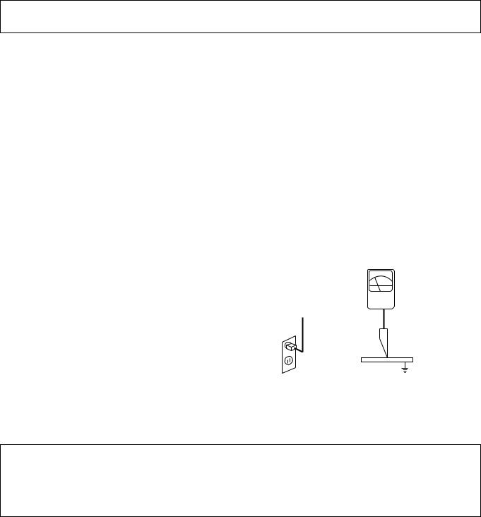
7.Antes de devolver este aparato al cliente, haga una verificación de fuga de corriente sobre las partes metálicas del gabinete expuestas, tales como antenas, terminales, cabezas de tornillos, tapas de metal, palancas de control etc., para estar seguro de que el equipo funciona sin peligro de choque eléctrico. Enchufe el cordón directamente al tomacorriente de la línea de AC 100-240V.
No utilice una línea aislada de transformador durante esta verificación. Use un voltímetro de 1000 Ohmios por voltio
de sensibilidad o más, en la forma que se describe a continuación.
Cuando la unidad está ya conectada a la AC, pulse el conmutador primero poniéndolo en "ON" (encendiendo) y luego en "OFF" (apagando), mida desde un punto de tierra conocido, tal como una (cañería de metal, una manija metálica, una tubería etc.) a todas las partes metálicas expuestas del receptor de televisión (antenas, manijas de metal, gabinetes de metal, cubiertas de metal, palancas de control etc.,) especialmente cualquiera de las partes metálicas expuestas que puedan ofrecer un camino hacia el chasis. Ninguna medición de corriente eléctrica debe exceder de 0.5 miliamperios. Repita la prueba cambiando la posición del enchufe en el tomacorriente. Cualquier medición que no esté dentro de los límites especificados aquí representan un riesgo potencial de choque eléctrico que debe ser eliminado antes de devolver el equipo al cliente.
|
|
|
|
|
|
LEAKAGEProbador |
|
|
Aparato |
|
|
||||
|
DEVICE |
|
|
|
|
CURRENTde fuga de |
|
|
bajoUNDER |
|
|
|
|
TESTERcorriente |
|
|
TEST |
|
|
|
|
|
|
|
examen |
|
|
|
|
|
+- |
|
|
|
|
|
|
|
|
Pruebe todas
TEST ALL lasEXPOSEDsuperficiesMET AL
SURFACES metálicas
2-WIRE CORD
Tambien pruebe cón
ALSO TEST WITH los enchufes al reves
PLUG REVERSED
(utilizando adaptador
(USING AC ADAPTER
PLUGen casoASnecesario)REQUIRED)
La lectura no debe
(READING SHOULD excederNO T BEde ABOVE0.5mA
0.5mA)
Tierra
EAR TH suelo
GROUND
AVISO SOBRE SEGURIDAD DE PRODUCTOS
Muchas de las partes, electricas y mecánicas en este chasis tienen caracteristicas relacionadas con la seguridad. Estas caracteristicas frecuentemente pasan desapercibidas en las inspecciones visuales y la proteccion que proporcionan contra la RADIACION DE RAYOS-X no siempre necesariamente se obtiene al mismo grado cuando se reemplazan piezas o componentes diseñados para voltajes o vatajes mayores, etc. Las piezas que tienen estas caracteristicas de seguridad se identifican por la marca  impresa sobre el diagrama esquematico. Antes de reemplazar alguno de esos componente, lea cuidadosamente la lista de este manual. El uso de partes de reemplazo que no tengan las mismas caracteristicas de seguridad, como se especifica en la lista de partes, puede crear Radiacion de Rayos-X.
Copyright©2009 LG Electronics. Inc. All right reserved. |
- 3 - |
LGE Internal Use Only |
Only for training and service purposes |
|
|
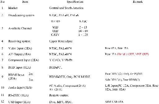
ESPECIFICACIONES
NOTE : Specifications and others are subject to change without notice for improvement.
V Application Range
This spec is applied to PDP TV used PP91A/B Chassis.
Chassis |
Model Name |
Market |
Brand |
Remark |
|
|
|
|
|
|
|
PP91A/B |
50PQ30R-MA |
Central and South America |
LG |
|
|
|
|
|
|
|
|
|
|
50PQ60R-TA |
NON-EU |
|
|
|
|
|
|
|
|
|
|
42PQ600R-ZA |
EU |
|
|
|
|
|
|
|
|
|
|
42PQ200R-ZA |
EU |
|
|
|
|
|
|
|
|
|
|
50PQ200R-ZA |
EU |
|
|
|
|
|
|
|
|
|
|
42PQ70BR-TA |
NON-EU |
|
|
|
|
|
|
|
|
|
|
42PQ60R-MA |
Central and South America |
|
|
|
|
|
|
|
|
|
|
42PQ30R-TA |
NON-EU |
|
|
|
|
|
|
|
|
V Specification
Each part is tested as below without special appointment.
1)Temperature : 25±5°C (77±9°F), CST : 40±5
2)Relative Humidity: 65±10%
3)Power Voltage: Standard Input voltage (100-240V~, 50/60Hz)
*Standard Voltage of each product is marked by models.
4)Specification and performance of each parts are followed each drawing and specification by part number in accordance with SBOM.
5)The receiver must be operated for about 20 minutes prior to the adjustment.
VTest Method
1)Performance : LGE TV test method followed.
2)Demanded other specification
Safety : CE, IEC specification
EMC : CE, IEC
Model Name |
Market |
Remark |
Appliance |
|
|
|
|
|
|
42PQ600R-ZA |
EU |
Safety: IEC/EN60065, |
EMI: EN55013, |
TEST |
|
|
EMS: EN55020 |
|
|
42PQ200R-ZA |
|
|
|
|
|
|
|
|
|
50PQ200R-ZA |
|
|
|
|
|
|
|
|
|
50PQ60R-TA |
NON-EU |
Safety: IEC/EN60065, |
EMI: CISPR13 |
TEST |
|
|
|
|
|
42PQ70BR-TA |
|
|
|
|
|
|
|
|
|
42PQ30R-TA |
|
|
|
|
|
|
|
|
|
50PQ30R-MA |
Central and South |
|
|
|
|
America |
|
|
|
42PQ60R-MA |
|
|
|
|
|
|
|
|
|
Copyright©2009 LG Electronics. Inc. All right reserved. |
- 4 - |
LGE Internal Use Only |
Only for training and service purposes |
|
|

VModule Specification
(1)42” XGA
No |
Item |
|
Specification |
Remark |
|
|
|
|
|
1 |
Display Screen Device |
42 inch 16:9 Color plasma Display Module |
PDP |
|
|
|
|
|
|
2 |
Aspect Ratio |
16:9 |
|
|
|
|
|
|
|
3 |
PDP Module |
PDP42G2####, |
Glass Filter |
|
|
|
RGB Closed Type |
|
|
|
|
|
|
|
4 |
Operating Environment |
1) |
Temp. : 0 ~ 60deg |
|
|
|
2) |
Humidity : 20 ~ 80% |
LGE SPEC. |
|
|
|
|
|
5 |
Storage Environment |
3) |
Temp. : -20 ~ 60deg |
|
|
|
4) |
Humidity : 10 ~ 90% |
|
|
|
|
|
|
6 |
Input Voltage |
AC100-240V~, 50/60Hz |
Maker: LGIT |
|
|
|
|
|
|
(2) 50” WXGA
No |
Item |
|
Specification |
Remark |
|
|
|
|
|
1 |
Display Screen Device |
50 inch 16:9 Color plasma Display Module |
PDP |
|
|
|
|
|
|
2 |
Aspect Ratio |
16:9 |
|
|
|
|
|
|
|
3 |
PDP Module |
PDP50G2####, |
Glass Filter |
|
|
|
RGB Closed(Well) Type |
|
|
|
|
|
|
|
4 |
Operating Environment |
1) |
Temp. : 0 ~ 55deg |
|
|
|
2) |
Humidity : 20 ~ 80% |
LGE SPEC. |
|
|
|
|
|
5 |
Storage Environment |
3) |
Temp. : -10 ~ 60deg |
|
|
|
4) |
Humidity : 10 ~ 90% |
|
|
|
|
|
|
6 |
Input Voltage |
AC100-240V~, 50/60Hz |
Maker: LGIT |
|
|
|
|
|
|
(3) 50” FHD
No |
Item |
|
Specification |
Remark |
|
|
|
|
|
1 |
Display Screen Device |
50 inch 16:9 Color plasma Display Module |
PDP |
|
|
|
|
|
|
2 |
Aspect Ratio |
16:9 |
|
|
|
|
|
|
|
3 |
PDP Module |
PDP50H3####, |
Glass Filter |
|
|
|
RGB Closed Type |
|
|
|
|
|
|
|
4 |
Operating Environment |
1) |
Temp. : 0 ~ 55deg |
|
|
|
2) |
Humidity : 20 ~ 80% |
LGE SPEC. |
|
|
|
|
|
5 |
Storage Environment |
3) |
Temp. : -10 ~ 60deg |
|
|
|
4) |
Humidity : 10 ~ 90% |
|
|
|
|
|
|
6 |
Input Voltage |
AC100-240V~, 50/60Hz |
Maker: LGIT |
|
|
|
|
|
|
Copyright©2009 LG Electronics. Inc. All right reserved. |
- 5 - |
LGE Internal Use Only |
Only for training and service purposes |
|
|

VModel General Specification
(1)EU Spec.(ZA)
(2) NON-EU Spec.(TA)
|
|
|
|
|
|
|
|
|
|
|
|
|
|
|
|
|
|
|
|
|
|
|
|
|
|
|
|
|
|
|
|
|
|
|
|
|
|
|
|
|
|
|
|
|
|
|
|
|
|
|
|
|
|
|
|
|
|
|
|
|
|
|
|
|
|
|
|
|
|
|
|
|
|
|
|
|
|
|
|
|
|
|
|
|
|
|
|
|
|
|
|
|
|
|
|
|
|
|
|
|
|
|
|
|
|
|
|
|
|
|
|
|
|
|
|
|
|
|
|
|
|
|
|
|
|
|
|
|
|
|
|
|
|
|
|
|
|
|
|
|
|
|
|
|
|
|
|
|
|
|
|
|
|
|
|
|
|
|
|
|
|
|
|
|
Copyright©2009 LG Electronics. Inc. All right reserved. |
- 6 - |
|
|
|
LGE Internal Use Only |
|||||
Only for training and service purposes |
|
|
|
|
|
|||||
(3) Central and South America(MA)
|
|
|
|
|
|
|
|
|
|
|
|
|
|
|
|
|
|
|
|
|
|
|
|
|
|
|
|
|
|
|
|
|
|
|
|
|
|
|
|
|
|
|
|
|
|
|
|
|
|
|
|
|
|
|
|
|
|
|
|
|
|
|
|
|
|
|
|
|
|
|
|
|
|
|
|
|
|
|
|
|
|
|
|
|
|
|
|
|
|
|
|
|
|
|
|
|
|
|
|
|
|
|
|
|
|
|
|
|
|
|
|
|
|
|
|
|
|
|
|
|
|
|
|
|
|
|
|
|
|
|
|
|
|
|
Copyright©2009 LG Electronics. Inc. All right reserved. |
- 7 - |
|
LGE Internal Use Only |
|||||
Only for training and service purposes |
|
|
|
|||||
INSTRUCCIONES DE AJUSTE
1. Application Range
This spec sheet is applied to all of the PP91A/B chassis.
2.Specification
(1)Because this is not a hot chassis, it is not necessary to use an isolation transformer. However, the use of isolation transformer will help protect test instrument.
(2)Adjustment must be done in the correct order.
(3)The adjustment must be performed in the circumstance of 25±5°C of temperature and 65±10% of relative humidity if there is no specific designation.
(4)The input voltage of the receiver must keep 100~240V, 50/60Hz.
(5)The receiver must be operated for about 5 minutes prior to the adjustment when module is in the circumstance of over 15°
-In case of keeping module is in the circumstance of 0°C, it should be placed in the circumstance of above 15°C for 2 hours
-In case of keeping module is in the circumstance of below -20°C, it should be placed in the circumstance of above 15°C for 3 hours,.
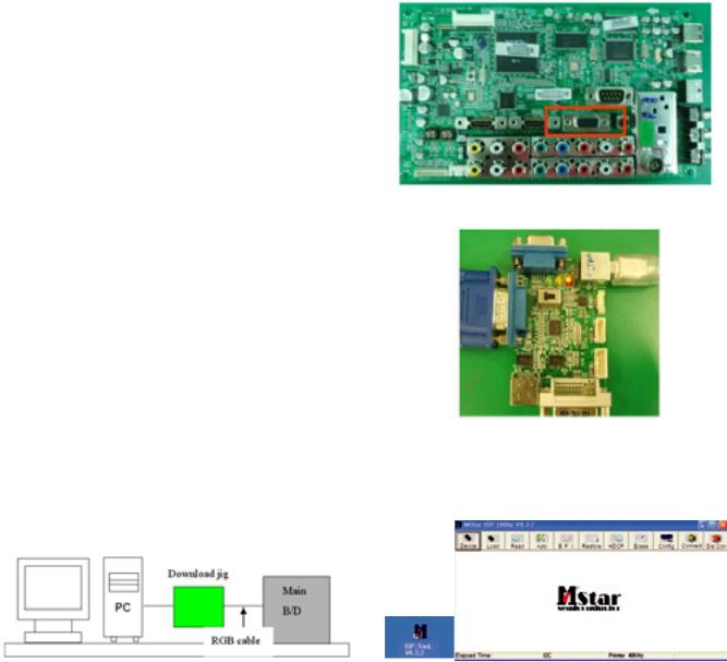
3.S/W Program Download
3-1. Profile
This is for downloading the s/w to the flash memory of the IC603
3-2. Equipment
(1)PC
(2)ISP_tool program
(3)Download jig
3-5. Download Method (By using MSTAR JIG)
(1) Preliminary Steps
1) Connect the download jig to D-sub jack
2)Connect the PC to USB jack
(2)Download Steps
1)Execute ‘ISP Tool’ program in PC, then a main window will be opened
3-3. Connection Structure
Double click
3-4. Connection Condition
(1)IC name and circuit number : Flash Memory and IC603
(2)Use voltage : 3.3V (5 pin)
(3)SCL : 15 pin
(4)SDA : 12 pin
(5)Tact time : about 2min and 30seconds
Copyright©2009 LG Electronics. Inc. All right reserved. |
- 8 - |
LGE Internal Use Only |
Only for training and service purposes |
|
|

2) Click the connect button and confirm “Dialog Box”.
3)Click the Config button and Change speed E2PROM Device setting : over the 350Khz
4) Read and write bin file
Click “(1)Read” tab, and then load download file(XXXX.bin) by clicking “Read”.
5)Click “Auto(2)” tab and set as below
6)Click “Run(3)”.
7)After downloading, check “OK(4)” message.
3-6. Download Method (By using USB Memory Stick)
[Caution]
-Using ‘power on’ button of the control R/C, power on TV.
-USB file (EPK) version must be bigger than downloaded version of main B/D.
(1)Using ‘Power ON’ button of the control R/C, Power on TV.
(2)Insert the USB memory stick to the SET.
(3)Display USB loding message then, push the ‘Exit’ Key of control R/C
(4)Push the ‘MENU’ Key and move the cusor ‘OPTION’ of OSD ( Fig. 1)
*Caution: Don’t push the ‘OK’ key.Just cusor is on the ‘OPTION’ menu.
( Fig. 1)
(5) Push the “7” key of control R/C continuously.
Then, Display “TV Software Update” Pop-up menu. (Fig. 2)
( Fig. 2)
Copyright©2009 LG Electronics. Inc. All right reserved. |
- 9 - |
LGE Internal Use Only |
Only for training and service purposes |
|
|
 Loading...